APPLICATION AND COMMISSIONING MANUAL FOR NUMERICAL OVER CURRENT & EARTH FAULT PROTECTION RELAY TYPE MJT 315
|
|
|
- Joella Watts
- 5 years ago
- Views:
Transcription
1 JUNE 2009 APPLICATION AND COMMISSIONING MANUAL FOR NUMERICAL OVER CURRENT & EARTH FAULT PROTECTION RELAY TYPE MJT 315 EASUN REYROLLE LIMITED 1
2 ISSUE NO : Ist Issue DATE OF ISSUE : DEPARTMENT : Applications Support 2
3 3
4 CONTENTS CHAPTER PAGE 1. APPLICATION INSTALLATION 9 3. COMMUNICATION GUIDELINES FOR SETTING 5. COMMISSIONING DRAWING WIRING DIAGRAM 32 4
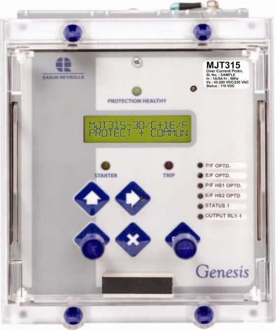
5 CHAPTER 1 - APPLICATION 1.1. INTRODUCTION The type MJT315 numeric over current protection relay combines the power and flexibility of microprocessor technology. A wide range of protection elements, characteristics and true RMS measurements are available. Moreover, supervisory components and self-monitoring features give high confidence of serviceability. MJT 315 Three Pole Over Current and Earth Fault Relay with two High set elements 1.2. MULTIPLE CHARACTERISTICS MJT315 relay is suitable for various inverse characteristics and also for definite time lag characteristic, any one of them selectable at site independently for phase and earth fault Standard Inverse characteristic (SI 3 or SI 1) SI 3 theoretical operating time is 3 seconds at 10 time s current setting at time multiplier setting (TMS) Theoretical operating time of the standard inverse characteristics SI 1 is 1.3 seconds at 10 time s current setting at TMS Very Inverse Characteristic (VI) VI curve is suited to networks where there is a significant reduction in fault current as the distance from the source increases. The operating time is shorter for large fault currents and increases at a greater rate as the fault current decreases. This permits the use of the same time multiplier setting for several relays in series Extremely Inverse Characteristic (EI) EI is very much useful to grade the relay with the fuse and applications where short duration transient over currents occurs. E.g. Motor starting or reacceleration Long Time Inverse Characteristic (LTI) LTI is generally used for Standby Fault protection for Neutral / Ground Earthing Resistor. The same characteristics can be used to guard against overheating / over loading protection, when it matches with thermal characteristics of the motor, generator, transformer or capacitor banks Definite Time Lag Characteristic (DTL) DTL is used for grading the system where source impedance determines fault current level and the fault current does not vary to a considerable amount down the length of the line DC TRANSIENT FREE HIGHSET On transmission lines or transformer feeders where the source impedance is small compared with the protection circuit, to reduce the tripping time at high fault level the highset instantaneous over current & earth elements are used in addition to the inverse time over current & earth element. MJT 315 relay is provided with two stages of highset elements in both phase fault and earth fault. First stage of highset element is having DTL characteristic and second stage of highset element is 5
6 instantaneous element. Depending upon the point on wave switching of the fault and the X/R ratio of the system, the initial current may have DC offset. The highset over current unit being instantaneous one, it should not over reach due to initial DC offset current though it may exceed the highset pick-up value. The MJT 315 relay is provided with the DC transient free highset elements, which will not over reach for DC transient condition RESET TIME DELAY The increasing use of plastic cables, both, conventionally buried types and aerial bundled conductor types have given rise to the number of "pecking" or "flashing intermittent faults on distribution systems. At the fault position, the plastic melts and temporarily reseals the faulty cable for a short time, after which the insulation fails again. The same phenomenon has occurred in joint boxes where an internal flashover temporarily reseals. The behavior of different types of over current relays under flashing fault condition is compared in Fig. 1. The repeating process often caused electromechanical disc relays to "ratchet up and eventually trip the faulty circuit provided that the reset time of the relay was longer than the time between successive flashes. Early electronic IDMTL relays with instantaneous reset features were not at all effective in dealing with this condition and only tripped after the flashing fault had developed into a solid permanent fault. To overcome this, MJT 315 relay has a reset time setting which can be user programmed to be either instantaneous or delayed from 1 to 60 seconds. On the other hand, on overhead line networks, particularly where reclosers are incorporated in the protected system, instantaneous resetting is desirable to ensure that, on multiple shot reclosing schemes, correct grading between the source relays and the relays associated with the reclosers is maintained. Fig 1: Flashing Fault Protection 6
7 1.5. SIMPLE BUSBAR PROTECTION For a simple radial system, where there is one incoming and several outgoing feeders, with MIT Relays simple busbar protection can be applied as shown in fig 2. The optional starter output relay with one changeover contact can be used for this application. The break contacts of the starter output of the outgoing feeders can be connected in series (so that any fault on the outgoing feeder, the trip circuit is not energized) and this combination is connected in series with the normally open repeat contacts of the starter output of the incoming feeder. The above combination trips the incoming feeder with minimum delay for a bus fault. The repeat contact if necessary has to give a small time delay to avoid racing of contacts. When there is a line fault say at line D, Starter contact of D opens and hence there is no Bus trip. When there is a bus fault, N/O contact of A closes and there is a trip. Figure 2. Simple Busbar Protection Scheme 7
8 Thus same MJT 315 Relay can be used for simple Bus bar protection in addition to the normal duty of protecting the distribution feeders. This is an economic form of Bus bar protection, which can be used, where dedicated form of Bus bar protection cannot be justified. 1.6 CAPACITOR BANK PROTECTION The TRUE RMS measurement of the MJT 315 Relay makes it very much suitable for protection of capacitor banks to guard against the faults in the capacitor and the leads between the circuit breaker and units ROUGH BALANCE SCHEME Where a dedicated transformer differential protection is not economically justified the MJT 315 relay can be used in the differential circuit of the transformer current balance protection. See fig 3. Since the relay is having lower settings down to 5% even on the phase fault elements, suitable setting can be adopted for this scheme. It may be necessary to change the setting during tap changing of the transformer. The magnetic inrush current while charging the transformer will not affect the relay function as the relay is set for time delayed operation LIGHTLY LOADED SYSTEMS Figure 3. Rough Balance Scheme The lower range of the current setting available in the phase fault setting makes the relay suitable for lightly loaded system. The setting can be changed to higher value when the system load is upgraded. 8
9 CHAPTER 2 -INSTALLATION 2.1. UNPACKING On receipt, remove the relay from the carton box in which it was received and inspect it for obvious damage. It is recommended that the relay is not removed from the relay case. To prevent the possible ingress of dirt, the sealed polythene bag should not be opened until the relay is to be used. If damage has been sustained, please inform Easun Reyrolle Ltd., for necessary action STORAGE When the relay is not required for immediate use, it should be returned to its original carton and stored in a clean dry place HANDLING The relay s electronic circuits are protected from damage by static discharge when the relay is housed in its case. When relay is withdrawn from the case, static handling procedures should be observed: Before removing the relay from its case the operator must first ensure that he is at the same potential as the relay, by touching the case The relay must not be handled by any of the relay terminals at the rear of the chassis Ensure that anyone else handling the relay is at the same potential As there are no user serviceable parts and adjustable user settings inside the relay, there should be no requirement to remove any modules from the chassis. If any modules are removed or tampered with, then the guarantee will be invalidated MOUNTING Mount the relay using two mounting straps and one earth strap. Ensure that an earth wire is connected to the earth strap from the earth terminal 23. Terminal 23 should be directly connected to the system ground. Only settings or trip details can be accessed via the pushbuttons when the cover is fitted. To change the settings the front cover has to be removed. Sealing arrangement is provided in one of the four knurling screws fitted on the cover. Sealing can be done using a sealing wire. Thus mechanical interlock is provided to avoid unauthorized setting change. 9
10 CHAPTER 3 - COMMUNICATION The communication interface complies with IEC or MODBUS RTU with 2 wire RS485 physical layout. COMMUNICATION PORT - RS 485 Normal shielded twisted pair cable should be used for communication. The relay can be connected directly if the data terminating equipment (Master) has RS 485 port in it, otherwise a RS485 to RS232 converter is required. Maximum distance between the master and the slave should be limited up to 1200 meters. COMMUNICATION PROTOCOL Protocol defines a message structure that controllers will recognize and use, regardless of the type of networks over which they communicate. It describes the process a controller uses, to request access to another device, how it will respond to requests from the other devices, and how errors will be detected and reported. It establishes a common format for the layout and contents of message fields. This relay supports IEC protocol. IEC PROTOCOL The communicative interface complying with IEC has two distinct features. 1. Standard features, for example, Spontaneous Events, Metering, active group change and General Interrogation as defined in IEC Private commands to access additional features, for example, active group change and altering the relay settings. Transmission Rate Different baud rates are provided for flexibility of the user. They are 19200, 9600, bits per second (BPS) All the above baud rates can be used for the maximum distance (1200 meters) specified by the RS 485 standard. Parity Defines the method of transmission as using EVEN parity. However, in some instance an alternative may be required. The relay allows the setting of parity to EVEN NONE ODD 10
11 Address Up to 32 relays can be connected to a master. The address of the relay must be set to a value between 1 and 254 inclusive before communication can take place. All relays must have a unique address. Address 255 is reserved as a global broadcast address. Communication ON / OFF setting is also provided. 11
12 CHAPTER 4 GUIDELINES FOR SETTING 4.1 HUMAN MACHINE INTERFACE (HMI) The user friendly HMI provided on the front panel has following features: 1. LCD display - To display settings, readings, fault records etc 2. Green LED - Protection healthy indication 3. Orange LED (STARTER) - Starter indication 4. Red LED (TRIP) - Trip indication, 5. Red LED (in Key) - Sub Menu ON indication 6. Up Key - Scrolling up/ increasing value when submenu is ON. 7. Down Key - Scrolling down/ decreasing value when submenu is ON. 8. Sub menu key - To change settings. When submenu LED is ON, then the user can edit the sub menu by scrolling using up/down keys. When sub menu LED is OFF, then the user returns to the main menu. Now using up/down key the user can scroll through the main menu. 9. Key - Enter / Reset / Cancel / To check Version/ Pass-code 10. Configurable LEDs ( Red 2nos & Orange 4nos) 4.2 SETTING INSTRUCTIONS How to operate HMI Remove the front cover by unscrewing the four knurling screws. Apply DC voltage between the terminals 13 and 14. Connect terminal 15 to earth. When the relay powers up, it takes few seconds, to complete the self-checking process. Then the protection healthy LED becomes ON. When the screen becomes blank, press the key, the display shows, 12
13 MJT O/C +1 E/F PROTECT+COMMUN Use key to scroll down. For each key press, the main menu displays each of the settings in the order shown below. GROUP ACTIVE G1 PF CURRENT G1=100 G2=100 PF CHARCTERISTIC G1=NI 3 G2=NI 3 PF TIME(MULT) G1=1.000 G2=1.000 PF HIGHSET 1 G1=OFF G2=OFF PF HS1 TIME G1=0 G2=0 PF HIGHSET 2 G1=OFF G2=OFF EF CURRENT G1=80 G2=80 EF CHARCTERISTIC G1=NI 3 G2=NI 3 EF TIME(MULT) G1=1.000 G2=1.000 EF HIGHSET 1 G1=OFF G2=OFF EF HS1 TIME G1=0 G2=0 EF HIGHSET 2 G1=OFF G2=OFF RESET TIME G1=0 G2=0 STATUS CONFIG S1-S8 OUTPUT CONFIG X H.RESET R1-R6 LED CONFIG X H. RESET L1-L6 TIME Hours Min Sec DATE Day Month Year COMMUNICATION ON Baud Parity Address rate 9600 EVEN 001 Instruments P/F C.T RATIO 300 / 1 13
14 E/F C.T RATIO 300 / 1 r =0.000 b=0.000 R =00.00 B=00.00 y=0.000 e=0.000 Y=00.00 E=00.00 FAULT DATA 1 FAULT DATA 2 FAULT DATA 3 Clear all FAULT DATA PASSWORD NONE 4.3 TO CHANGE THE SETTINGS To change the settings, press the submenu key. The sub menu key can be pressed only when starter /Trip LED is not glowing. When starter LED is glowing, no setting change can be done ACTIVE GROUP Press key to get ACTIVE GROUP setting. Press submenu Key, Red LED in the key is lit to indicate that the sub menu is activated. The options available in the sub menu are G1 G2 GROUP ACTIVE G1 When the display shows, group active = G1, the relay permits to change the settings ingroup G1 only. GROUP ACTIVE G2 Now the display shows, group active = G2, the relay permits to change the settings in-group G2 only. PF CHARACTERISTICS Press key repeatedly to get PF Characteristics menu, press submenu Key, Red LED in the key is lit to indicate that the sub menu is activated. Pressing or key repeatedly the sub menu will scroll down in the following order on the display. NI 1.3 NI 3 14
15 VI EI LTI and DTL PF CHARACTERISTIC G1=NI 3 G2=NI PF CURRENT Press key repeatedly to get PF Current menu, press submenu Key, Red LED in the key is lit to indicate that the sub menu is activated. The current setting is available from 5% to 250%. The setting can be increased/ decreased in steps of 1% by pressing up/down keys respectively. PF CURRENT G1=100% G2=100% PF TIME MULTIPLIER Press key repeatedly to get PF time multiplier setting menu, press submenu Key, Red LED in the key is lit to indicate that the sub menu is activated. The time multiplier setting depends on the characteristic selected. For IDMTL characteristics the time multiplier setting varies from to The setting can be increased/ decreased in steps of by pressing up/down keys respectively. For DTL the time setting varies from 0.00 to seconds. The setting can be increased/ decreased in steps of 0.01 seconds by pressing up/down keys respectively. PF TIME(MULT) G1=1.000 G2= PF HIGHSET1 CURRENT Press key repeatedly to get PF Highset1 setting menu, press submenu Key, Red LED in the key is lit to indicate that the sub menu is activated. The Highset1 current setting is available from 5% to 3000%. The setting can be increased/ decreased in steps of 1% by pressing up/down keys respectively. It can also be put OFF. PF HIGHSET 1 G1=OFF G2=OFF PF HIGHSET1 TIME Press key repeatedly to get PF Highset 1 time setting menu, press submenu Key, Red LED in the key is lit to indicate that the sub menu is activated. The Highset1 time setting varies from 0.00 to seconds. The setting can be increased/ decreased in steps of 0.01 seconds by pressing up/down keys respectively. PF HS1 TIME G1=0.00 G2=
16 4.3.7 PF HIGHSET2 CURRENT Press key repeatedly to get PF Highset2 setting menu, press submenu Key, Red LED in the key is lit to indicate that the sub menu is activated. The Highset2 current setting is available from 50% to 3000%. The setting can be increased/ decreased in steps of 50% by pressing up/down keys respectively. It can also be put OFF. PF HIGHSET 2 G1=OFF G2=OFF EF CHARACTERISTICS Press key repeatedly to get EF Characteristics menu, press submenu Key,Red LED in the key is lit to indicate that the sub menu is activated. Pressing or key repeatedly the sub menu will scroll down in the following order on the display. NI 3 NI 1.3 VI EI LTI and DTL EF CHARCTERISTIC G1=NI 3 G2=NI EF CURRENT Press key repeatedly to get EF Current menu, press submenu Key, Red LED in the key is lit to indicate that the sub menu is activated. The current setting is available from 5% to 250%. The setting can be increased/ decreased in steps of 1% by pressing up/down keys respectively. EF CURRENT G1=100 G2= EF TIME MULTIPLIER Press key repeatedly to get EF time multiplier setting menu, press submenu Key, Red LED in the key is lit to indicate that the sub menu is activated. The time multiplier setting depends on the characteristic selected. For IDMTL characteristics the time multiplier setting varies from to The setting can be increased/ decreased in steps of by pressing up/down keys respectively. For DTL the time setting varies from 0.00 to seconds. The setting can be increased/ decreased in steps of 0.01 seconds by pressing up/down keys respectively. EF TIME(MULT) G1=1.000 G2=
17 EF HIGHSET1 CURRENT Press key repeatedly to get EF Highset1 setting menu, press submenu Key, Red LED in the key is lit to indicate that the sub menu is activated. The Highset1 current setting is available from 5% to 3000%. The setting can be increased/ decreased in steps of 1% by pressing up/down keys respectively. It can also be put OFF. EF HIGHSET 1 G1=OFF G2=OFF EF HIGHSET1 TIME Press key repeatedly to get EF Highset 1 time setting menu, press submenu Key, Red LED in the key is lit to indicate that the sub menu is activated. The Highset1 time setting varies from 0.00 to seconds. The setting can be increased/ decreased in steps of 0.01 seconds by pressing up/down keys respectively. EF HS1 TIME G1=0 G2= EF HIGHSET2 CURRENT Press key repeatedly to get EF Highset2 setting menu, press submenu Key, Red LED in the key is lit to indicate that the sub menu is activated. The Highset2 current setting is available from 50% to 3000%. The setting can be increased/ decreased in steps of 50% by pressing up/down keys respectively. It can also be put OFF. EF HIGHSET 2 G1=OFF G2=OFF RESET TIME Press key repeatedly and get EF reset time menu. To set the reset time, press submenu Key, Red LED in the key is lit to indicate that the sub menu is activated. The reset time setting is available from 0 second to 60 seconds. It can be set in steps of 1 seconds. The reset time can be increased by pressing key and decreased by pressing key. RESET TIME G1=0 G2= STATUS CONFIGURATION Press key repeatedly and get status configuration for S1 to S8, press side arrow key, sub menu key, BLKFUN<--S1-->RLY Press side arrow sub menu key again, Red LED in the key is lit to indicate that the sub menu is activated. The user has to press the sub menu key multiple times to enter into appropriate character position and set the options. 17
18 Character Positions Function 1 to 7 BLOCKING FUNCTIONS (character positions 1-6) User options different inhibit functions with code. For character positions, (1 to 7) the following options are available by pressing up/ down arrow DASH - No inhibit 1 - Inhibit 1 - P/F Char (IDMTL/ DTL) 2 - P/F High-set 1 3 P/F High-set 2 4 E/F Char (IDMTL/ DTL) 5 - E/F High-set 1 6 E/F High-set 2 8 Select between Inverted and Non-inverted status inputs 1 - Inverted inputs DASH - Non-inverted inputs 9 Change group 1 - G1 select 2 - G2 select (3 - if trip circuit supervision is given) (11 to 16)** OUTPUT RELAY CONFIGURATION (character positions 11-16) RLY1 RLY2 RLY4 RLY5 RLY 6 RLY 3 For Character positions, (11 to 16)** the following options are available. 1. The contact will operate for the status input. Dash. The contact will not operate for the status input. 0 (Zero). Reset the output contact for the status input. For the given status input, the preset output contacts will operate. Even multiple contacts can be operated with a single status input. Press side arrow sub menu key again, Red LED in the key goes off. Press down key to get the Status1 Pick up/ drop off time delay menu PU dt 1 <--S1--> DO dt 1 s m
19 Press the side arrow key to set the Pick up time delay. Use up/down arrow keys to set the time delay. Press the side arrow key again to edit the drop off delay. Use up/down arrow keys to set the time delay. CHARACTER AND SUB MENU OPTIONS Character Positions Function User options (Delay time in Sec) 1 Minute (or) second Select whether the time delay is set in minutes or seconds 2-5 Pick up delay 10 ms (0.01 Sec) to min 6 Dash - 7 Display S for Sec Drop off delay 10 ms (0.010 Sec) to min 15 Dash - 16 Display S for Sec - Further pressing down key remaining 7 status will appear OUTPUT CONFIGURATION On pressing down arrow from STATUS INPUT VIEW menu, the user gets into O/P RELAY CONFIG menu.the user has to press side arrow key to enter. The red LED in the side arrow button will be OFF. In the sub menu, the side key LED will be functional. Self, Hand / Elect Reset o/p Each output relay can be assigned to multiple protection functions. O/P RELAY CONFIG TO VIEW Press side arrow to enter MENU 1 MENU 2 MENU 3 MENU 4 Self, Hand/ Elect reset O/P PF Starter O/P Rly PF Char O/P Rly PF Highset1 O/P Rly 19
20 MENU 5 MENU 6 MENU 7 MENU 8 MENU 9 PF Highset2 O/P Rly EF Starter O/P Rly EF Char O/P Rly EF Highset1 O/P Rly EF Highset2 O/P Rly ** Protection healthy is not user configurable. So no user settable options will be provided LED CONFIGURATION Press down key repeatedly and get LED configuration for L1to L6, press side arrow key sub menu key, Self / Hand Reset LED Press side arrow key again, Red LED in the key is lit to indicate that the sub menu is activated. CHARACTER AND SUB MENU OPTIONS Character Positions Function 1 Led1 hand reset/self reset 2 Led2 hand reset/self reset 3 Led3 hand reset/self reset 4 Led4 hand reset/self reset 5 Led5 hand reset/self reset 6 Led6 hand reset/self reset Press side arrow key again, Red LED in the key goes off to indicate that the sub menu is deactivated. Press down key then rest of the LED menu appears as follows Character Positions S1 S2 Function 20
21 S3 S4 S5 S6 S7 S8 P/F STARTER P/F CHARACT P/F HIGHSET1 P/F HS1 TIME P/F HIGHSET 2 E/F STARTER E/F CHARACT E/F HIGHSET1 E/F HS1 TIME E/F HIGHSET 2 OUTPUT Rly1 OUTPUT Rly2 OUTPUT Rly3 OUTPUT Rly4 OUTPUT Rly5 OUTPUT Rly TIME Press key repeatedly and get the time menu. Time is displayed as HOURS: MINUTES: SECONDS, in 24 hours fashion. To set the time press submenu Key, Red LED in the key is lit to indicate that the sub menu is activated. Now hour can be increased/decreased by using UP arrow key or Down arrow key. Press the side arrow submenu Key, for the second time to edit the minute setting. Press the side arrow submenu key, for the third time to edit the seconds setting. 21
22 To set the hours setting only, press submenu key once. The sub menu LED glows. Now increase or decrease the setting by pressing up/down keys. Now press submenu key thrice. Now the sub menu key goes off. Now press x key, to save the settings. To set the minutes setting only, press submenu key twice. The sub menu LED glows after one press itself. Now increase or decrease the setting by pressing up/down keys. Now press submenu key twice. Now the sub menu key goes off. Now press x key, to save the settings. To set the seconds setting only, press submenu key thrice. The sub menu LED glows after one press itself. Now increase or decrease the setting by pressing up/down keys. Now press submenu key once. Now the sub menu key goes off. Now press x key, to save the settings. TIME Hours Min Sec DATE Press key repeatedly and get the date menu. Date is displayed as DATE: MONTH: YEAR. To set the time press submenu Key, 3mm LED in the key is lit to indicate that the sub menu is activated. Now date can be increased or decreased by using the up/down arrow keys. Press the submenu Key, for the second time to edit the month setting. Press the side arrow submenu key, for the third time to edit the year setting. DATE Day 22 Month 11 Year 05 To edit COMMUNICATION Press key repeatedly and get the communication menu. Press submenu Key, Red LED in the key is lit to indicate that the sub menu is activated. Communication can either be made ON or OFF by scrolling using up/down arrow keys. COMMUNICATION ON When communication is OFF, baud rate, parity and address settings are not displayed BAUD, PARITY, ADDR The baud rate, parity and address are displayed only when communication is ON. Press key repeatedly and get this menu. Press submenu key, 3mm LED in the key is lit to indicate that 22
23 the sub menu is activated. Now Baud rate can be edited. Press submenu key, repeatedly for the second and third time respectively to edit parity and address. Baud rate can be set as or Parity can be set as EVEN ODD or NONE The relay address can be set between 1 to 254. Scroll using up/down arrow keys to increase/decrease the values. Baud rate Parity Address 9600 EVEN INSTRUMENTS Press key repeatedly and get this menu. The instrument readings are displayed in this menu. Press key repeatedly and get E/ F C.T Ratio menu. The ratio can be selected from 5 to for Primary current and 1 or 5 for Secondary current. The user can not edit this menu. The user can only view the measured secondary current r, y, b, e poles and primary current R,Y,B,E poles. Instruments r =0.000 b=0.000 y=0.000 e=0.000 Instruments R =00.00 B=00.00 Y=00.00 E=
24 FAULT DATA Press key repeatedly and get this menu. The user can not edit this menu. This menu gives a summary of 3 recent faults. The fault data menu displays Date & time of fault, Active Group, current reading of all four poles at the time of fault, starter/ trip, IDMTL/ DTL/ H1/ H2 operated 29/10/05 10:05: G2 R PHASE IR=12.20 IDMTL (S)H1(T); Y PHASE FAULT DATA1 IY=12.24 IDMTL (S) H1(T); B PHASE IB=12.28 IDMTL (S) H1(T); EARTH- FAULT IE= IDMTL (T) H1(T) 27/10/05 12:56: G1 R PHASE IR=2.00 IDMTL (S)H1(T); Y PHASE FAULT DATA2 IY=2.04 IDMTL (T); B PHASE IB=2.02 IDMTL (T); EARTH-FAULT IE= 1.98 IDMTL (T) 27/10/05 12:56: G1 R PHASE IR=2.00 IDMTL (S)H1(T); Y PHASE FAULT DATA3 IY=2.04 IDMTL (T); B PHASE IB=2.02 IDMTL (T); EARTH-FAULT IE= 1.98 IDMTL (T) In fault data1, IDMT(S) indicates that IDMT starter is raised. IDMT(T) indicates that IDMT Trip is raised. H1(S) indicates that Highset1 starter is raised. H1(T) indicates that Highset1 Trip is raised. H2(T) - indicates that Highset2 Trip is raised CLEAR ALL FAULTS Press key repeatedly and get this menu. Press submenu key, and scroll up or down. The menu has yes/ no option. Setting this menu to yes, clears the fault data. Clear all FAULT DATA PASSWORD Press key repeatedly and get this menu. Press the submenu key once to edit the first character and repeatedly press the submenu to edit successive characters. When password is NONE, the user can view as well as edit the settings. When password is other than NONE, PASSWORD N O N E To save the settings, press submenu key repeatedly and make the submenu LED OFF. Now press key to save the settings. 24
25 4.4 SAVE/CANCEL SETTINGS SAVING THE EDITED SETTINGS 1. Ensure all the chosen settings are as per requirements. 2. Ensure starter/ trip LED is not ON. 3. Go to corresponding menu and enter into the appropriate sub menu by pressing (Ensure LED is ON). 4. Use or keys, to edit the present setting. 5. When required new setting appears on the screen Press key, again so that the LED is OFF. Now press key to save the required new setting. 6. The display goes blank. This indicates that settings have changed. 7. Scroll to the particular menu and ensure that the setting changes have been stored TO CANCEL SETTING CHANGES WHILE EDITING While the particular setting is being edited (using or key) with submenu LED ON, by pressing key, the previous setting of this particular menu is restored. Note: If submenu key is pressed again and submenu LED is OFF, then on pressing key Settings will be saved. 4.5 RESET TRIP LED To reset the trip LED, press the RESET button. The trip LED can be reset only when starter LED is not glowing. 25
26 CHAPTER 5 COMMISSIONING 5.1. REQUIRED TEST EQUIPMENTS 500V insulation test sets. Variable secondary injection current source rated 10A or greater. Time interval meter Primary injection equipment A DC supply with a nominal voltage within the working range of the relays DC auxiliary supply ratings 5.2. INSPECTION Ensure that all connections are tight and in accordance with the relay wiring diagram and the scheme diagram. Check if the relay is correctly programmed and the relay is fully inserted into the case APPLYING SETTINGS The relay settings for the particular application should be applied before any secondary testing is started PRECAUTIONS Before testing commences, the equipment should be isolated from the current transformers and the CTs to be short-circuited, in line with the local site procedures. The tripping and alarm circuits should also be isolated, where practical. Also, ensure that trip links are removed. Ensure that correct DC auxiliary voltage and polarity is applied. See the relevant scheme diagrams for the relay connections TESTS Insulation Connect together all relay CT terminals and measure the insulation resistance between these terminals and all the other relay terminals connected together to earth. Connect together the terminals of the DC auxiliary supply (only +ve and -ve) and measure the insulation resistance between these terminals and all other terminals connected together to earth. Connect together all the output relay terminals and measure the insulation resistance between these terminals and all other terminals connected together to earth. A minimum value of 2. 5 to 3 Meg ohms can be considered as satisfactory value. 26
27 Secondary Injection Select the relay configuration and settings for the application. Note that the MJT315 relay can be connected either as 1A or 5A-rated device. The user should check this before commencing secondary test Pick Up And Reset The test checks accuracy of the current settings for the relay s main over current characteristics. Apply single-phase current into one of the current inputs. Slowly increase the current until the starter LED (yellow) operates and record the pick up current in Table 1. Reduce the current until the LED goes off and record this as the reset level. Repeat this test for each pole. Check that all the pick up current levels are measured within 104% ± 4% or ± 10mA of the applied setting. Check that the reset levels are 94% of the setting. POLE PICK-UP SETTING MEASURED PICK-UP PICK-UP ERROR MEASURED RESET RESET ERROR PHASE A PHASE B PHASE C E/F TABLE IDMTL / DTL Characteristics This test checks the accuracy of the main time delay characteristics (IDMTL / DTL). Select the relay current setting characteristics and time multiplier settings as required and then inject a level of current which is a multiple of the relay setting. A time interval meter should be connected to the correct output contact terminals. The timer should be started by the source and stopped by the relay trip contacts. Each pole should be tested. A secondary injection timing test circuit is illustrated in Fig. 4. The secondary injection test equipment should be made 'OFF', once the relay contact is closed Table 2 shows theoretical value of each characteristic with time multiplier set to Record the actual results in Table 3 and check that the measured times are within ± 5% or ± 30-msecs of theoretical value. CURVE 2xIs 5 xis 10 xis 20 xis SI SI EI VI LTI DTL * * * * 27
28 * USER SETTING TABLE 2 Pole Phase A Characteristic (SI3,SI1,EI,VI LTI,DTL) 2xIs 5xIs 10xIs 20xIs Delay Error (±5%) Delay Error (±5%) Delay Error (±5%) Delay Error (±5%) Phase B Phase C E/F TABLE Highset Program the current settings for the highset characteristics to the required level. Inject a level of current below the setting of the relay and then increase the current until the output operates. Record the pickup level for each pole in Table 4 and confirm that in each case it occurs within 100% ± 4% or ± 10 ma of applied setting. When the highset setting is above the continuous thermal rating of the relay, care should be taken, such that the duration of the applied current should not damage the relay. Refer catalogue for thermal rating. ()i POLE HIGHSET SETTING MEASURED PICK-UP ERROR PHASE A PHASE B PHASE C E/F TABLE 4 28
29 Output Relays MJT315 relay has six programmable O/P contacts. In this first contact is having change over contact arrangement and the remaining five contacts are normally open type. These are to be tested during secondary injection testing. In addition to this, one normally closed contact is provided for relay unhealthiness purpose Primary Injection Primary injection tests are essential to check the ratio and polarity of the transformers as well as the secondary wiring. Using the circuit shown in Fig.5 / Fig.7, check the current transformer ratio and CT phase to earth connection. Inject a current of sufficient magnitude.the secondary current is Is = Primary current / CT ratio Use the circuit shown in Fig.6 / Fig.8 to check the current transformer ratio and the CT phase to phase connections. CT should also be tested for knee point voltage Putting Into Service After completing all tests satisfactorily, the relay should be put into service as follows: 1. Make a final check of the secondary wiring and tightness of all terminal connections 2. Insert the DC supply fuse 3. Check the relay healthy indication/display 4. Replace the relay cover 5. Insert the trip links 6. Perform trip test by secondary injection 7. Remove all test connections 29
30 CHAPTER 6 DRAWINGS Fig 4 - Secondary Injection Timing Test Circuit (Terminals shown are for 1A rating) Fig 5 - Primary Injection Test Circuit (Phase To Earth) (Terminals shown are for 1A rating) Similar test shall be conducted on A & C phase CTs 30
31 Fig 6 - Primary Injection Test Circuit (Phase To Phase) (Terminals shown are for 1A rating) Similar test shall be conducted on BC & CA phases 31

32 53 MJT A 55 5A A 51 5A A 47 5A A A 28 R - Phase Y - Phase B - Phase Neutral RL6 Protection Unhealthy RL1 RL2 RL3 R Y B + VE DC AUXILIARY SUPPLY - VE RL4 RL5 RS 485 Communication Port Earth + VE - VE 15 Cable Shield Case Earth VE - VE + VE - VE + VE - VE Status Input 3 Status Input 4 Status Input 5 Group change Input + VE 1 - VE Status Input 1 + VE - VE Status Input 2 + VE - VE VE - VE + VE - VE + VE - VE Status Input 6 Status Input 7 Status Input 8 WIRING DIAGRAM FOR MJT 315 RELAY Drawing No. :- CEDBW50002 EASUN REYROLLE LIMITED HOSUR, INDIA. REV. No. Sig. DATE No. Sig. DATE No. Sig. DATE DATE 30/06/07 CHECKED G. Vivek SUPERSEDES SHEET 1 OF 1 DRAWN K.Saravanan APPROVEDS.Muthukrishnan
AUGUST 2001 APPLICATION AND COMMISSIONING MANUAL MIT161 RELAY EASUN REYROLLE LIMITED
 AUGUST 2001 APPLICATION AND COMMISSIONING MANUAL MIT161 RELAY EASUN REYROLLE LIMITED 1 Issue No : 2nd Issue Date of Issue : 30.08.2001 Department : TP-CTS 2 SENSITIVE CURRENT PROTECTION PROTECTION HEALTHY
MiCOM P122C Time-Overcurrent Protection
 Protection Relays 01 MiCOM P122C Time-Overcurrent Protection Customer Benefits 1A/5A software setting 4 function keys Compact unit for flush and wall-surface mounting Comprehensive measurements Disturbance
MiCOM P521. Fast feeder differential protection
 01 Fast feeder differential protection The relay provides high-speed two-ended current differential unit protection of overhead lines and underground cables in applications such as ring mains and parallel
MiCOM P521. Fast Feeder Differential Protection
 01 Fast Feeder Differential Protection The relay provides high-speed two-ended current differential unit protection of overhead lines and underground cables in applications such as ring mains and parallel
DGSZV-EP DIGITAL GALVANIC LONGITUDINAL DIFFERENTIAL PROTECTION. Application field
 DGSZV-EP DIGITAL GALVANIC LONGITUDINAL DIFFERENTIAL PROTECTION The digital galvanic longitudinal differential protection of type DGSZV-EP is part of device family named EuroProt. This short description
1S20. Arc Fault Monitor Relay. Features. Introduction. ARC Fault Protection
 Technical Bulletin Arc Fault Monitor Relay Features Compact, economic design Simple panel mounting for retrofit applications Two or three arc sensor inputs Two high speed tripping duty arc sense output
MiCOM P124 T&D. Self and Dual Powered Overcurrent Relays
 PROTECTION MiCOM P124 Self and Dual Powered Overcurrent Relays MiCOM P124 are numerical relays designed to offer complete overcurrent protection without requiring any external auxiliary supply. They can
2T105. Multi Range Digital Setting Time Delay Relay. Features. Application. Operation
 2T15 Multi Range Digital Setting Time Delay Relay Technical Bulletin Features Four time ranges -.99s, -9.9s, -99s, -99s High accuracy & repeatability timing compensated for output relay delay Time settings
Feeder protection relay SPAA 121 C. Product Guide
 Issued: April 1999 Status: Updated Version: C/06.03.2006 Data subject to change without notice Features Two-phase low-set phase overcurrent unit with definite time or inverse time characteristic Two-phase
7SG14 Duobias-M Transformer Protection
 7SG4 Duobias-M Transformer Protection Document Release History This document is issue 200/02. The list of revisions up to and including this issue is: Pre release 200/02 Document reformat due to rebrand
Earth-fault Relay SPAJ 110 C. Product Guide
 Issued: April 1999 Status: Updated Version: C/12.04.2006 Data subject to change without notice Features Low-set neutral overcurrent stage with definite time or inverse time characteristic High-set neutral
2C138. Sensitive Earth Fault Relay. Features. Application. Operation
 Technical Bulletin 2C138 Sensitive Earth Fault Relay Features High sensitivity (0.1% of I n ) 2 nd & 3rd harmonic & HF noise suppression - tuned to 50 Hz Optional reset functions Instantaneous (Fast),
REYROLLE 2RMLG. Operating Recommendations
 2RMLG Operating Recommendations SAFETY The commissioning and maintenance of protection equipment should only be carried out by skilled personnel trained in protective relay operation and capable of observing
Combined Overcurrent and Earth-fault Relay SPAJ 141 C. Product Guide
 Combined Overcurrent and Earth-fault Product Guide Issued: April 1999 Status: Updated Version: C/19.04.2006 Data subject to change without notice Features Three-phase, low-set phase overcurrent unit with
MiCOM P124. Self and Dual Powered Overcurrent Relays. Protection Relays
 01 Self and Dual Powered Overcurrent Relays are numerical relays designed to offer complete overcurrent protection without requiring any external auxiliary supply. They can be applied to a wide variety
MiCOM P521. Fast Feeder Differential Protection. Protection Relays. MiCOM P521 CUSTOMER BENEFITS
 MiCOM 01 MiCOM Fast Feeder Differential Protection The MiCOM relay provides high-speed two-ended current differential unit protection of overhead lines and underground cables in applications such as ring
Reyrolle Protection Devices. 7SG21 DDB20 Multi Range Digital Setting Time Delay Relay. Energy Management
 Reyrolle Protection Devices 7SG21 DDB20 Multi Range Digital Setting Time Delay Relay Energy Management 7SG21 DDB20 Digital Time Delay Induction disc reset emulation Replacement of induction disc timing
7SR242 Duobias Multi-Function 2-Winding Transformer Protection Relay
 7SR242 Duobias Multi-Function 2-Winding Transformer Protection Relay Document Release History This document is issue 2010/06. The list of revisions up to and including this issue is: 2010/06 Additional
Overcurrent and Arc Protection by Reyrolle Alexander Erokhin. 21, 2017 I Berlin
 Overcurrent and Arc Protection by Reyrolle Alexander Erokhin VAR Partner Day September 20-21, 21, 2017 I Berlin Reyrolle Product Range by SIEMENS Challenges We Meet for our Customers Easy-to-use protection
Combined Overcurrent and Earth-fault Relay SPAJ 140 C. Product Guide
 Combined Overcurrent and Earth-fault Product Guide Issued: April 1999 Status: Updated Version: C/18.04.2006 Data subject to change without notice Features Three-phase, low-set phase overcurrent unit with
MiCOM P111. Three phase and earth fault overcurrent relays
 Three phase and earth fault overcurrent relays The relays are suitable for all the application where overcurrent and/or earth-fault protection are required. Thanks to its favorable price vs technical features
sigma the power to protect Instruction Manual C-453EM
 sigma monitor relay GROUND Fault RELAY / resistor monitor sigma the power to protect Instruction Manual C-453EM sigma monitor relay Neutral Grounding Resistors (NGR) are an integral and critical component
1/32-DIN TEMPERATURE CONTROLLER INSTALLATION, WIRING AND OPERATION MANUAL FORM 3882
 1/32-DIN TEMPERATURE CONTROLLER INSTALLATION, WIRING AND OPERATION MANUAL FORM 3882 This manual is intended for use in support of installation, commissioning and configuration of the 1/32-DIN Temperature
(1) Description of Operation 7SR224 Recloser Controller
 Description of Operation 7SR224 Recloser Controller") (1) Description of Operation 7SR224 Recloser Controller DOCUMENTATION SET This document is part of a set. The full list of documents in the set, and the publication numbers under which they can be ordered,
(1) Description of Operation 7SR224 Recloser Controller DOCUMENTATION SET This document is part of a set. The full list of documents in the set, and the publication numbers under which they can be ordered,
7SR21 Non-Directional 7SR22 Directional Overcurrent Relay
 7SR21 Non-Directional 7SR22 Directional Overcurrent Relay Document Release History This document is issue 2010/05. The list of revisions up to and including this issue is: 2010/05 Additional Comms modules
GRD110 FEATURES APPLICATION
 FEATURES Overcurrent protection for phase and earth faults with IDMTL or DTL. Three instantaneous elements with DTL. Programmable reset characteristics. Sensitive earth fault protection (SEF). Restricted
7SR11 and 7SR12 Description of Operation
 7SR11 and 7SR12 Description of Operation Document Release History This document is issue 2012/02. The list of revisions up to and including this issue is: 2012/02 AC auxiliary power supply added 2012/01
7SR18 Solkor Line Differential Protection Energy Management
 Reyrolle Protection Devices 7SR18 Solkor Line Differential Protection Energy Management 7SR18 Solkor five or eight user-programmable binary output contacts and three or six user programmable status inputs
Reyrolle Protection Devices. 7SR11 and 7SR12 Argus Overcurrent Relays. Answers for energy
 Reyrolle Protection Devices 7SR11 and 7SR12 Argus Overcurrent Relays Answers for energy 7SR11 and 7SR12 Argus Overcurrent Relays 74T/CCS Trip & Close Circuit Supervision 60VTS VT Supervision Control 79
MRI1-IU - Voltage controlled time overcurrent relay
 MRI1-IU - Voltage controlled time overcurrent relay Contents 1 Introduction and application 2 Features and characteristics 3 Design 3.1 Connections 3.1.1 Analog input circuits 3.1.2 Output relays 3.1.3
Reyrolle Protection Devices. 7SG117 Argus 7 Synchronising Relay. Answers for energy
 Reyrolle Protection Devices 7SG117 Argus 7 Synchronising Relay Answers for energy 7SG117 Argus 7 Synchronising Relay Fig 1. Independent check & system synchronising settings Adjustable slip frequency,
Sensitive Earth-fault Relay SPAJ 111 C. Product Guide
 Issued: April 1999 Status: Update Version: C/12.04.2006 Data subject to change without notice Features Sensitive low-set neutral overcurrent stage with definite time characteristic High-set neutral overcurrent
INTRINSICALLY SAFE DUPLEXER PROTECTION. ELECTRONICS, INC Vulcan Road Apopka, Florida MOTOR INSTRUCTION MANUAL
 INTRINSICALLY SAFE DUPLEXER INSTRUCTION MANUAL MOTOR PROTECTION ELECTRONICS, INC. 2464 Vulcan Road Apopka, Florida 32703 Phone: Website: (407) 299-3825 www.mpelectronics.com Operating Program Revision:
Function permission: yes/no. Operating range: 0.10 to 30 xin (step 0.01) Operating time: 0.02 to 300 s (step 0.01 s) Activation level 100%
 Operating time: 0.02 to 300 s (step 0.01 s) Activation level 100%") Operating range: 0.10 to 30 xin (step 0.01) 50P(2) Activation level 100% Deactivation level 95% Timer accuracy: 30 ms Operating range: 0.10 to 30 xin (step 0.01) 50N/G(2) Activation level 100% Deactivation
Operating range: 0.10 to 30 xin (step 0.01) 50P(2) Activation level 100% Deactivation level 95% Timer accuracy: 30 ms Operating range: 0.10 to 30 xin (step 0.01) 50N/G(2) Activation level 100% Deactivation
Interface Definition RISH EM 2340/1320/30/ _Rev. D - 8/2016
 Interface Definition RISH EM 2340/1320/30/40 1 2-60-006-00-00494_Rev. D - 8/2016 2 Section DIGITAL MULTIFUNCTION INSTRUMENT Contents 1. Introduction Programmable Multi-function Energy Meter Installation
Reyrolle Protection Devices. 7SR11 and 7SR12 Argus Overcurrent Relays. Answers for energy
 Reyrolle Protection Devices 7SR11 and 7SR12 Argus Overcurrent Relays Answers for energy 7SR11 and 7SR12 Argus Overcurrent Relays Control 79 Auto Reclose 86 Lockout CB Control Features Cold Load Settings
NPW800R RETROFITTING. Power and Volatge Protection Relay
 RETROFITTING Power and Volatge Protection Relay NPW800R (R3 case) is dedicated to the refurbishment of CEE WTG 7000 relays (R3 case) providing the measurement of apparent (S), active (P) and reactive (Q)
XRI1-ER Earth fault relay for isolated and compensated mains
 XRI1-ER Earth fault relay for isolated and compensated mains Contents 1 Introduction and application 2 Features and characteristics 3 Design 3.1 Connections 3.1.1 Analog input circuits 3.1.2 Blocking input
VIP 40/45 VIP 400/410
 40/45 400/410 Selection guide 01 PM100573 40/45 PM100576 400/410 self-powered integrated protection relay Optimised performance for transformer, incomer, feeder and bus riser protection Complete engineered
isma-b-mg-ip User Manual Global Control 5 Sp. z o.o. Poland, Warsaw
 isma-b-mg-ip User Manual Global Control 5 Sp. z o.o. Poland, Warsaw www.gc5.pl Table of content 1 Introduction... 4 1.1 Revision history... 5 1.2 Safety rules... 5 1.3 Technical specifications... 6 1.4
MIC-2 MKII, Multi-instrument DATA SHEET
 MIC-2 MKII, Multi-instrument DATA SHEET Measurements All 3-phase AC measurements True RMS 4-Quadrant energy Power Quality Analysis Replaces analogue meters RS-485 Modbus RTU protocol TCP/IP Modbus (optional)
Reyrolle Protection Devices. 7SR10 Argus User Manual Overcurrent and Earth Fault Relay
 Reyrolle Protection Devices 7SR10 Argus User Manual Overcurrent and Earth Fault Relay Siemens Protection Devices Limited 2 7SR10 Argus Contents Contents Technical Manual Chapters 1. Description of Operation
7SR191 Capa Capacitor Protection Relay Energy Management
 Reyrolle Protection Devices 7SR191 Capa Capacitor Protection Relay Energy Management 7SR191 Contents Contents Technical Manual Chapters 1. Description of Operation 2. Settings & Instruments 3. Performance
SIA-B. Overcurrent & Earth Fault Protection Relay for Secondary Distribution. Dual & Self Powered / Standard CTs. Main characteristics
 SIA-B Overcurrent & Earth Fault Protection Relay for Secondary Distribution Dual & Self Powered / Standard CTs Main characteristics The SIA-B is an protection relay with self powered and dual powered (Self-powering
7SR242 Duobias Transformer Protection Relay Answers for energy.
 Reyrolle Protection Devices 7SR242 Duobias Transformer Protection Relay Answers for energy. 2 Contents Technical Manual Chapters 1. Description of Operation 2. Settings, Configuration & Instruments 3.
CURRENT PROTECTION RELAY SMPR-1
 CURRENT PROTECTION RELAY SMPR-1 1.- ORION ITALIA SERIES MODBUS PROTOCOL. The ORION ITALIA SERIES implement a subset of the AEG Modicon Modbus serial communication standard. Many devices support this protocol
Reyrolle Protection Devices. 7SG13 Delta Protection and Control Relays. Answers for energy
 Reyrolle Protection Devices 7SG13 Delta Protection and Control Relays Answers for energy 7SG13 Delta Protection and Control Relays User Interface 20 character x 2 line backlit LCD Menu navigation keys
Auxiliary Units for 7SR23 High Impedance Protection Energy Management
 Reyrolle Protection Devices Auxiliary Units for High Impedance Protection Energy Management Siemens Protection Devices Limited 2 Auxiliary Units for High Impedance Protection Description 7XG15 High Impedance
7SR11 and 7SR12 Settings and Instruments
 7SR11 and 7SR12 Settings and Instruments Document Release History This document is issue 2012/01. The list of revisions up to and including this issue is: 2012/01 Software Maintenance 2011/06 Software
MiCOM P123R. Overcurrent Relays P123R/EN AD/A11. Upgrade Documentation
 MiCOM P123R Overcurrent Relays Upgrade Documentation MiCOM P123R Page 1/14 CONTENTS MiCOM P123R ADDENDUM: MiCOM P12X UPDATE DOCUMENTATION 3 P12X/EN IT/EB6: INTRODUCTION 4 P12x/EN TD/Eb6: TECHNICAL DATA
Reyrolle Catalogue Answers for Energy
 Reyrolle Protection Devices Reyrolle Catalogue Answers for Energy Index Compact Overcurrent Argus C 7SR11 & 7SR12 1 Multifunction Overcurrent Argus M 7SR21 & 7SR22 2 Multifunction Reclose Controller Recloser
Protection Products. Catalogue
 Protection Products Numerical Multi-Function Relays Catalogue Selection Guide Product Range Feeder Protection Model Argus 1 Argus 2 Argus 7 Argus 8 Delta Delta Lite Motor Protection Model Rho 3 Description
High-Tech Range IRI1-ES- Sensitive Earth Fault Current Relay
 High-Tech Range IRI1-ES- Sensitive Earth Fault Current Relay IE ON RESET.5 X1 t IE X1.6%.2.4.8 1.6 X1.1s.2.4.8 1.6 X2 OFF ON S1 S2 IRI1-ES IRI1-ES C&S Electric Limited (Protection & Control Division) Contents
MiCOM P721 & P723. Numerical High Impedance Differential Relay. Protection Relays. Customer Benefits
 01 MiCOM P721 & P723 Numerical High Impedance Differential Relay The new P72x high impedance differential protection series provides an independent and simple high impedance differential protection solution
Relion 605 series. Self-powered feeder protection REJ603 Product Guide
 Relion 605 series Relion 605 series Relion 605 series Self-powered feeder protection Product Guide Product version: 3.0 Contents 1. Description... 3 2. Relay functions... 3 3. Protection functions... 4
7SR11 and 7SR12 Argus Overcurrent Relays Answers for infrastructure & cities.
 Reyrolle Protection Devices 7SR11 and 7SR12 Argus Overcurrent Relays Answers for infrastructure & cities. 7SR11 and 7SR12 Argus Overcurrent Relays Supervision 60CTS CT Supervision 74T/CCS Trip & Close
INSTALLATION & COMMISIONING GUIDE
 SIA C Self Power O/C & E/F Protection Relay INSTALLATION & COMMISIONING GUIDE www.fanox.com SIAC11500032AG_Rev. 12 1 / 32 1. RECEPTION & INSTALLATION... 3 1.1. Relay unpacking... 3 1.2. Relay verification...
Model 7705 Control Module
 www.keithley.com Model 7705 Control Module User s Guide PA-696 Rev. D / October 2006 A G R E A T E R M E A S U R E O F C O N F I D E N C E Safety Precautions The following safety precautions should be
2V67-S Four Stage Over / Under Voltage Relay
 Technical Bulletin 2V67-S Four Stage Over / Under Voltage Relay Features Large graphics display panel Instantaneous voltage display 20 to 130V PU setting range 0.1V setting resolution Adjustable pick up
IRI1-ES Sensitive Earth Fault Current Relay. Manual IRI1-ES (Revision A)
") IRI1-ES Sensitive Earth Fault Current Relay Manual IRI1-ES (Revision A) Woodward Manual IRI1-ES GB Woodward Governor Company reserves the right to update any portion of this publication at any time. Information
IRI1-ES Sensitive Earth Fault Current Relay Manual IRI1-ES (Revision A) Woodward Manual IRI1-ES GB Woodward Governor Company reserves the right to update any portion of this publication at any time. Information
7SR11 & 7SR12 Argus Overcurrent Relay Energy Management
 Reyrolle Protection Devices 7SR11 & 7SR12 Argus Overcurrent Relay Energy Management 7SR11 & 7SR12 Argus Contents Contents Technical Manual Chapters 1. Description of Operation 2. Settings, Configuration
7SR21 Non-Directional 7SR22 Directional Overcurrent Relay
 7SR21 Non-Directional 7SR22 Directional Overcurrent Relay Document Release History This document is issue 2010/05. The list of revisions up to and including this issue is: 2010/05 Additional Comms module
Sensitive definite time or inverse time earth-fault stage for back-up residual earthfault
 Issued: April 1999 Status: Updated Version: B/09.11.2001 Data subject to change without notice Features Sensitive restricted earth-fault protection stage for fast, selective earth-fault protection Sensitive
SIA C. Self-powered overcurrent relay USER MANUAL
 SIA C Self-powered overcurrent relay USER MANUAL 1. RECEPTION, HANDLING, INSTALLATION... 9 1.1. Unpacking... 9 1.2. Reception of relays... 9 1.3. Handling electronic equipment... 9 1.4. Installation, commissioning
PGR-6101 MANUAL GROUND-FAULT & INSULATION MONITOR
 Tel: +1-800-832-3873 E-mail: techline@littelfuse.com www.littelfuse.com PGR-6101 MANUAL GROUND-FAULT & INSULATION MONITOR Revision 0-C-041918 Copyright 2018 by Littelfuse, Inc. All rights reserved. Document
GRE120. Motor Protection and Control for MV Systems
 Motor Protection and Control for MV Systems FEATURES Overcurrent protection for phase and earth faults (50/51P, 50/51N). Dependent and independent time characteristics (IDMTL and DTL). Restricted earth
Reyrolle Protection Devices. 7PG2113/4/5/6 Solkor Pilot Wire Current Differential Protection with integrated Overcurrent Guard. Answers for energy
 Reyrolle Protection Devices 7PG2113/4/5/6 Solkor Pilot Wire Current Differential Protection with integrated Overcurrent Guard Answers for energy 7PG2113/4/5/6 Solkor Pilot Wire Current Differential Protection
Iso DIN. User Manual. 1 channel Earth Fault Monitoring
 Page 1 of 5 2017 03 20 User Manual Iso DIN Iso DIN User Manual 1 channel Earth Fault Monitoring Megacon AB Ranhammarsvägen 20 S 168 67 Bromma Sweden Tel: 08 402 42 50 sales@megacon.se www.megacon.se eee
2H34. Definite Time Frequency Relay with ROCOF. Features. Operation. Application
 2H34 Definite Time Relay with ROCOF Technical Bulletin Features Large back lit display panel High resolution frequency & voltage display readout Four independent frequency s Independent time delay per
EDR-3000 Eaton Distribution Relay
 EDR-3000 Eaton Distribution Relay Technical Data New Information Description Page 1. General Description.......................... 2 2. Applications............................... 2 3. Drilling Pattern.............................
SEL-487B. A Powerful Solution for Busbar Differential Protection. Bus Differential and Breaker Failure Relay
 Bus Differential and Breaker Failure Relay A Powerful Solution for Busbar Differential Protection Features and Benefits Select the for the differential protection of busbar systems with up to 18 terminals.
g Energy Multilin Voltage Regulator Controller DGCV KEy BENEFITS APPLICATIONS FEATURES Metering & Monitoring Voltage Regulation Communications
 Multilin Voltage Regulator DGCV KEy BENEFITS Increases grid efficiency by optimizing voltage regulation Through deployment of the Volt/VAR system, the Multilin DGCV: - Enables up to a 6% reduction in energy
7SR23 DAD High Impedance Protection Relay Energy Management
 Reyrolle Protection Devices 7SR23 DAD High Impedance Protection Relay Energy Management 2 Siemens Protection Devices Limited 7SR23 DAD High Impedance Relay User Interface 20 character x 4 line backlit
PFC-10 Power Factor Controller
 PFC-10 Power Factor Controller Instruction Manual Ver. 6.0 / 2002 (2-2005 update) Table of Contents Page Subject 3 Starter ion 4-5 Installation Notes 6-7 Terminals Review & Control Wiring 8 Front-panel
GRD130 - FEATURES APPLICATION
 FEATURES Phase undervoltage protection with IDMTL or DTL. Phase overvoltage protection with IDMTL or DTL. Zero phase sequence overvoltage (neutral voltage displacement) protection with IDMTL/DTL. Negative
Soft Starter Remote Operator. Section 1.0 Introduction 1.1 Important user information General Manual description...2.
 Section 1.0 Introduction 1.1 Important user information... 2 1.2 General... 2 1.3 Manual description...2 Contents Section 2.0 Specification 2.1 General technical data...3 2.2 Dimensions...3 Section 3.0
Instruction Manual. ICENI/MA-01 MODBUS Master Module. Pub_ Issue 1
 Instruction Manual ICENI/MA-01 MODBUS Master Module Pub_363 - Issue 1 Regulateurs Europa Ltd 2014 The contents of this document are the exclusive Property of Regulateurs Europa Ltd They must not be copied
Common Departures Interconnecting Facilities Requirements
 Welcome to our e-rew Express. In our last issue, we discussed the common departures on metering installation requirements. This time, we would like to discuss the common departures on the customer low
installation Operation ADDRESS product diagram H8030/8031 INSTALLATION GUIDE
 POWER MONITORING INSTALLATION GUIDE H8030/8031 H8030/8031 Modbus Energy Meter Networked kw/kwh Transducer Product Identification Model Max Amps CT Size Enhanced Data Stream Meters H8030-0100- 100 H8030-0300-
H704-42(H)(E), H704-42/1(H)(E)
(E), H704-42/1(H)(E)") POWER MONITORING INSTALLATION GUIDE H704-42(H)(E), H704-42/1(H)(E) Branch Current Monitor DANGER NOTICE Installer's Specifications General: Operating Temp. Range 0 to 60 C (32 to 140 F) (
POWER MONITORING INSTALLATION GUIDE H704-42(H)(E), H704-42/1(H)(E) Branch Current Monitor DANGER NOTICE Installer's Specifications General: Operating Temp. Range 0 to 60 C (32 to 140 F) (
Reyrolle Protection Devices. 7SR10 Argus Overcurrent and Earth Fault Relay
 Reyrolle Protection Devices 7SR10 Argus Overcurrent and Earth Fault Relay 7SR10 Argus Overcurrent and Earth Fault Relay Control 79 Auto Reclose 86 Lockout CB Control CB Trip/Close Features Cold Load Settings
Earth Continuity Monitor
 Continuity Monitor For Model systems switching ELECTRONIC ENGINEERS Leaders in : Voltage-Dip Proofing Continuity Monitoring Contents Introduction... 3 Theory of operation... 3 Description... 4 Front panel
INSTRUCTION MANUAL FOR BREAKER FAILURE RELAY BE1-50BF. BE1-50BF BREAKER FAILURE RELAY Style No. XXX XXX XXXXX Serial No. HXXXXXXX
 INSTRUCTION MANUAL FOR BREAKER FAILURE RELAY BE1-50BF BE1-50BF BREAKER FAILURE RELAY Style No. XXX XXX XXXXX Serial No. HXXXXXXX P0048-40 Publication: 9190600990 Revision: G 01/10 *9190600990* INTRODUCTION
Company Directive ENGINEERING SPECIFICATION EE SPEC: 136
 Company Directive ENGINEERING SPECIFICATION EE SPEC: 136 Ancillary Electrical Equipment for Use in Conjunction with Switchgear and Protection/Control Panels NOTE: The current version of this document is
ASTAT XB/XBm Remote Operator
 ASTAT XB/XBm Remote Operator User Manual 1 Introduction 1.1 Important User Information Observe all necessary safety precautions when controlling the soft starter remotely. Alert personnel that machinery
RMS Product Presentation
 RMS Product Presentation THE RELAY SPECIALISTS relay monitoring systems pty ltd www.rmpl.com.au Relay Monitoring Systems Pty Ltd 6 Anzed Court - Melbourne - Australia Manufacturing in Australia Company
ABB Drives. User s Manual. Modbus Adapter Module RMBA-01
 ABB Drives User s Manual Modbus Adapter Module RMBA-01 Modbus Adapter Module RMBA-01 User s Manual 3AFE 64498851 REV A EN EFFECTIVE: 1.3.2002 2002 ABB Oy. All Rights Reserved. Safety instructions Overview
2 Table of Contents 1. TABLE OF CONTENTS. 1. Table of Contents Introduction Wiring Diagram Terminals Review...
 TPR-6 Temperature Protection Relay Instruction Manual Ver. June 1 st 2010 2 Table of Contents 1. TABLE OF CONTENTS 1. Table of Contents... 2 2. Introduction... 3 3. Wiring Diagram... 5 4. Terminals Review...
MCCB-250 MOLDED-CASE CIRCUIT BREAKER TESTER
 MCCB-250 MOLDED-CASE CIRCUIT BREAKER TESTER USER S MANUAL Vanguard Instruments Company, Inc. 1520 S. Hellman Ave. Ontario, California 91761, USA TEL: (909) 923-9390 FAX: (909) 923-9391 January 2015 Revision
Content FPC 200. USER MANUAL Mar Feeder F1 and F3 Motor M1 and M3 Busbar B2 and B3 Transformer T1 and T3
 Content FPC 200 USER MANUAL Mar 2017 Feeder F1 and F3 Motor M1 and M3 Busbar B2 and B3 Transformer T1 and T3 1 USER MANUAL FPC 200-3/2017 Content Preface Copyright Copyright Iskra d.d. Ljubljana, Slovenia
ATS Automatic transfer switches Advanced version
 87045 LIMOGES Cedex Phone :+33 05 55 06 87 87 Fax :+33 05 55 06 88 88 ATS CONTENTS PAGES 1. USE 1 2. RANGE 1 3. DIMENSIONS 1 4. ELECTRICAL AND MECHANICAL CHARACTERISTICS 2 5. CONFORMITY 4 6. EQUIPMENTS
2C138 User Guide. Sensitive Earth Fault Relay. Advanced Protection Devices. relay monitoring systems pty ltd. User Guide.
 2C138 User Guide Sensitive Earth Fault Relay relay monitoring systems pty ltd Advanced Protection Devices User Guide Test Manual 2C138 User Guide About This Manual This User Guide covers all 2C138 relays
MPI-DN, MPI-D MULTICHANNEL ELECTRONIC RECORDER for HART or RS-485/ MODBUS RTU SENSORS
 MPI-DN, MPI-D MULTICHANNEL ELECTRONIC RECORDER for HART or RS-485/ MODBUS RTU SENSORS 18 channels for HART / Modbus RTU sensors 2 digital channels 16 math channels 4 relay outputs for alarm or control
We will discuss two types of loss-of-potential (LOP) logic during this presentation:
 logic during this presentation:") 1 We will discuss two types of loss-of-potential (LOP) logic during this presentation: Traditional LOP, which uses traditional voltage and current elements to detect an LOP condition. Advanced LOP, which
1 We will discuss two types of loss-of-potential (LOP) logic during this presentation: Traditional LOP, which uses traditional voltage and current elements to detect an LOP condition. Advanced LOP, which
SACE Emax 2 Specification guide
 SACE Emax 2 Specification guide Specification Number: 26 01 20.17 Product Name: LOW VOLTAGE POWER CIRCUIT BREAKERS PART 1 GENERAL NOTE: ( ) Indicates option or a selection is to be made for quantity or
SIPROTEC easy 7SJ45 Numerical Overcurrent Protection Relay Powered by CTs
 SIPROTEC easy 7SJ4 Numerical Overcurrent Protection Relay Powered by CTs Function overview Fig. /1 Description The SIPROTEC easy 7SJ4 is a numerical overcurrent protection relay which is primarily intended
Multifunction Transducer MT440
 Multifunction Transducer MT440 Voltage and current auto range measurements up to 600V, 12.5A Universal wide auxiliary power supply range 24 300 Vdc, 40 276 Vac Power accuracy class 0.5 (EN 60 688), Up
Residual overvoltage relay
 Page 1 Issued: April 1999 Status: New Data subject to change without notice Features Definite-time residual overvoltage earthfault protection and supervision Two independent operation stages, e.g. one
Redundant Bus Protection Using High-Impedance Differential Relays. Josh LaBlanc
 Redundant Bus Protection Using High-Impedance Differential Relays Josh LaBlanc Purpose Discuss the configuration of the bus under study, and touch on the needs for redundant protection on the bus. Briefly
ADVANCED. Protection Co-ordination. H.H. Sheik Sultan Tower (0) Floor Corniche Street Abu Dhabi U.A.E
 Floor Corniche Street Abu Dhabi U.A.E") ADVANCED Protection Co-ordination H.H. Sheik Sultan Tower (0) Floor Corniche Street Abu Dhabi U.A.E www.ictd.ae ictd@ictd.ae Course Introduction: Distribution Networks are designed to serve loads in a
ADVANCED Protection Co-ordination H.H. Sheik Sultan Tower (0) Floor Corniche Street Abu Dhabi U.A.E www.ictd.ae ictd@ictd.ae Course Introduction: Distribution Networks are designed to serve loads in a