DIRIS B-10 & B-30. Multifunction meters and associated current sensors INSTRUCTION MANUAL. en/diris-b
|
|
|
- Aron Shaw
- 5 years ago
- Views:
Transcription


1 INSTRUCTION MANUAL DIRIS B-10 & B-30 Multifunction meters and associated current sensors EN en/diris-b
2 GB CONTENTS 1. TABLE OF CONTENTS 1. DOCUMENTATION HAZARDS AND WARNINGS Risk of electrocution, burns or explosion Risk of damaging the unit Liability PRELIMINARY OPERATIONS INTRODUCTION Range Functions Electrical values measured Dimensions Presentation of optional modules Range Dimensions Presentation of associated current sensors TE solid-core current sensors TR split-core current sensors TF flexible current sensors Adapters for 5A sensors MOUNTING Recommendations and safety DIN rail mounting Plate mounting Sealing accessory for sensors Installing the optional modules Installing an optional module on DIRIS B Installing an optional module on an optional module Installing TE solid-core sensors Mounting accessories DIN rail mounting Plate mounting Installing on a cable with clamping collar Bar mounting Sensors assembly Sealing accessories for sensors Installing TR split-core sensors Cable mounting stranded sensors TE mounting Installing the casing Cable mounting Bar mounting Installing the 5A adapter CONNECTION Connecting the optional modules Input/output modules Communication modules Connecting the current sensors Connection concept Details of the RJ12 connections for each current sensor EN DIRIS B A - SOCOMEC
3 Connecting to the electrical network and loads Connection of the functional earth STATUS AND AUTO-ADDRESSING LEDS Status LEDs Auto-addressing COMMUNICATION General information RS485 rules Radio-frequency (RF) rules EC Declaration of Conformity Communication tables CONFIGURATION Configuration using Easy Config Connection modes Using Easy Config Synchronisation of products Configuration from the DIRIS D-30 remote display Connection mode ALARMS Alarms upon events Electrical parameters Voltage and current unbalance (in a three-phase network) EN voltage quality events Consumption Analogue inputs Digital inputs Combination of alarms Setup alarms Current/voltage compatibility Incorrect direction of rotation (three-phase network) Faulty current sensor Setting up alarms ALARM LED on front Activation of an output Activation of an input RS485 Modbus Display and WEBVIEW FEATURES Mechanical features Electrical specifications Input characteristics Measuring characteristics Communication specifications Environmental specifications Electromagnetic compatibility Safety Service life DIRIS O optional modules characteristics DIRIS D-30 display characteristics Mechanical features Single product connection Electrical specifications Environmental specifications TE, TR and RF sensor features PERFORMANCE CLASSES Specification of the characteristics Evaluation of the power supply quality DIRIS B A - SOCOMEC EN 3
4 1. DOCUMENTATION sensors is available on the SOCOMEC website at the following address: 4 EN DIRIS B A - SOCOMEC
5 2. HAZARDS AND WARNINGS professionals. SOCOMEC shall not be held responsible for failure to comply with the instructions in this manual Risk of electrocution, burns or explosion Caution: risk of electric shock Ref. ISO B ( ) Caution Refer to the accompanying documentation each time this symbol is shown Ref. ISO B ( ) commissioning and operating the device and who have had appropriate training. He or she should have read and understood the various safety measures and warnings stated in the instructions. Always power the device with the correct rated voltage. Install the unit following the recommended installation instructions and in a suitable electrical cabinet. maximum prescribed currents. Do NOT clamp or pull out NON-INSULATED conductors carrying DANGEROUS VOLTAGE which Ref. IEC Failure to take these precautions could cause death or serious injuries Risk of damaging the unit Caution: risk of electric shock Ref. ISO B ( ) Caution Refer to the accompanying documentation each time this symbol is shown Ref. ISO B ( ) The unit is correctly installed. The network frequency indicated on the device is observed: 50 or 60 Hz. A maximum voltage at the voltage input terminals of 520 VAC phase/phase or 300 VAC phase/neutral is observed. maximum prescribed currents. Failure to respect these precautions could cause damage to the unit. DIRIS B A - SOCOMEC EN 5
6 2.3. Liability The unit must be installed in accordance with the rules given in this manual. The unit must be positioned within an installation which complies with the standards currently in force. Any cables which need to be replaced may only be replaced with cables with the correct ratings. 6 EN DIRIS B A - SOCOMEC
7 3. PRELIMINARY OPERATIONS installation. The packaging is in good condition The unit has not been damaged during transportation The device reference conforms to your order DIRIS B A - SOCOMEC EN 7
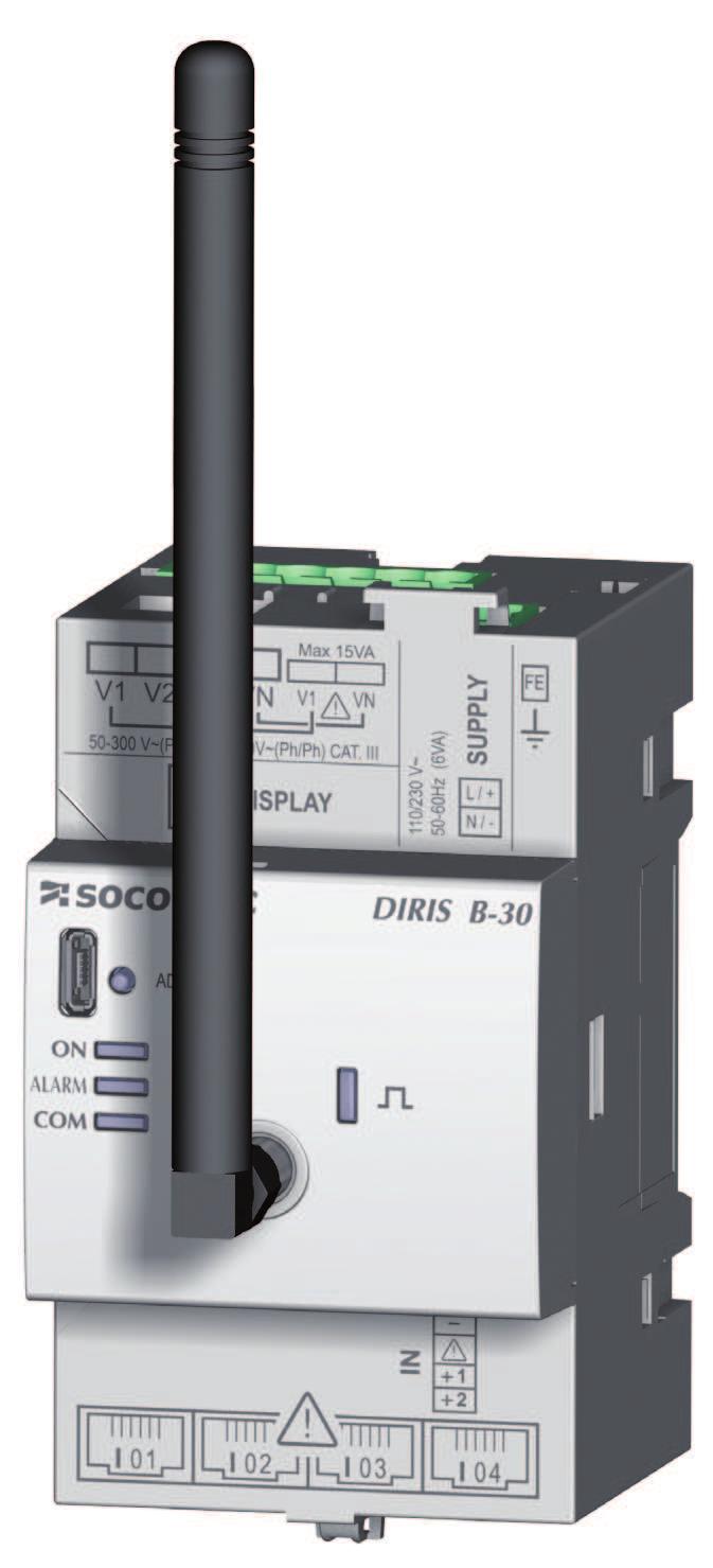
8 4. INTRODUCTION 4.1. It can be used to jointly analyse the single-phase and three-phase loads. Add optional modules to manage multi- can be guaranteed for all values measured. Energy Monitoring version). The data can also be accessed via the HYPERVIEW energy management software. The communication modes RS485 Modbus or radio frequency are available depending on the DIRIS B reference. management system. *PMD: Performance Measuring and Monitoring Device in accordance with IEC Range PMD DIRIS B-10 DIRIS B-30 RS DIRIS B-30 RF Communication RS485 RF Ref Accessories Height: 210mm Cable for remote antenna. Sealing kit. USB cable for configuration Functions 8 EN DIRIS B A - SOCOMEC
9 - - - Operation across 4 quadrants - Predictive power - current sensor used) for active energy and power in accordance with IEC THD and harmonics up to order 63 for voltage and current - - Current and voltage imbalance - Data logging - Recording of average electrical values - Recording and timestamping of min/max electrical values Metering Multi-tariff Alarm (*) - 25 timestamped alarms with boolean combination Connection - 4 current inputs with automatic recognition of the current sensors via a quick connection cable (RJ12 type) energy as per IEC Inputs / Outputs - 2 logical inputs - Communication - RS485 or radio frequency (RF) communication (see reference) - - Connects to a DIRIS D-30 remote display via RJ9 or D-50 / D-70 via RS Time synchronisation with the gateway - Auto-addressing in association with the gateway (*) Available only on the DIRIS B-30 RS (ref ) and DIRIS B-30 RF (ref ) DIRIS B A - SOCOMEC EN 9
10 Electrical values measured General Instant with timestamped Min/Max & Average with timestamped Min/Max DIRIS B-10 Phase Voltage - Neutral Phase to phase voltage Frequency f Current Total power and power by phase Predictive power Total power factor and power factor by phase DIRIS B-30 RS / RF Cos phi and tan phi Quality Instant & Average Phase to neutral voltage unbalance Phase to phase voltage unbalance Current unbalance Phase to neutral voltage THD Phase to phase voltage THD Current THD THD system Phase to neutral voltage harmonics orders 1 to 63 Phase to phase voltage harmonics orders 1 to 63 Current harmonics orders 1 to 63 Crest Factor Energies Total energy Partial energy 10 EN DIRIS B A - SOCOMEC
11 Dimensions Dimensions in/mm DIRIS G-40 / G-60 RF DIRIS B A - SOCOMEC EN 11


12 4.2. Presentation of optional modules functionalities in terms of inputs/outputs and communication modes Range DIRIS O-iod DIRIS O-ioa DIRIS O-it Module with 2 digital inputs/outputs Module with 2 analogue inputs/outputs Module with 3 temperature inputs DIRIS O-m DIRIS O-p DIRIS O-b/ip DIRIS O-b/mstp Modbus RS485 communication module PROFIBUS DPV1 communication module BACnet/IP communicationmodule BACnet MS/TP communication module Dimensions Dimensions in/mm A DIRIS O-iod DIRIS O-ioa DIRIS O-it DIRIS O-m DIRIS O-p DIRIS O-b/ip DIRIS O-b/mstp A 1.77in / 45mm 2.12in / 54mm 12 EN DIRIS B A - SOCOMEC
 0.1 0.2 0.3 0.")
13 4.3. Presentation of associated current sensors chain. TE / TR / TF current sensors DIRIS B Recommendations: It is recommended that all the current sensors are installed in the same direction. Connection cables for current sensors: RJ12 connection cables Number of cables Cable length (m) connectors* reference reference reference reference reference reference reference reference reference DIRIS B A - SOCOMEC EN 13


14 TE solid-core current sensors The TE solid-core current sensors are used to set up measurement points in a new or existing installation. They are easy to integrate as they are compact and respect the pitch of the circuit breakers. A wide range of accessories are is guaranteed Range TE-18 TE-18 TE-25 TE-35 TE-45 TE-55 Pitch 18 mm 18 mm 25 mm 35 mm 45 mm 55 mm Nominal current range In Actual range A A A A A A Maximum l Reference Pitch Nominal current range In Actual range Maximum l TE mm A Reference EN DIRIS B A - SOCOMEC
15 Dimensions L H L W H P T P W Dimensions in/mm TE-18 TE-25 TE-35 TE-45 TE-55 Pitch LxHxD Aperture (W) (T) (staggered assembly) 1.10 x 0.79 x x 20 x 45 ø 0.33 ø x 1.28 x x 32.5 x x x x 1.28 x x 32.5 x x x x 1.28 x x 32.5 x x x x 1.28 x x 32.5 x x x = = 2.52 / 64 = = Dimensions in/mm TE-90 DIRIS B A - SOCOMEC EN 15


16 TR split-core current sensors The TR split-core current sensors are used to set up measurement points in a new or existing installation without of the measurement chain is guaranteed Range Four models are available from 25A to 600A to analyse several types of loads. Cable passage diameter Nominal current range In Actual range TR-10 TR-16 TR-24 TR-36 10mm 16mm 24mm 36mm A A A A A A A A Maximum l 90A 120A 240A 720A Reference Dimensions L C B Ø W A P Dimensions in/mm TR-10 TR-16 TR-24 TR-36 H LxHxD 0.98 x 1.54 x x 39 x x 1.65 x x 42 x x 1.73 x x 44 x x 1.65 x x 42 x 111 W A B C EN DIRIS B A - SOCOMEC


17 without saturation. Flexible design and easy-opening system for quick installation in electrical enclosures. They are particularly suitable for adding measuring points in existing installations and for test campaigns Range sizes. TF-55 TF-120 TF-300 Loop length 55 mm 120 mm 300 mm Nominal current range In Actual range A A A Reference Dimensions L L E p Ø E Ø p Dimensions in/mm TF-55 TF-120 TF-300 Diameter p T L DIRIS B A - SOCOMEC EN 17
. 4.3.4.1. Range 5A adapter I nom. 5A I max. 6A Reference 4829 0599 4.3.4.2. Dimensions L H W P Dimensions in/mm LxHxD Aperture (W) 5A adapter 1.")
18 Adapters for 5A sensors The adapter lets you use a standard sensor supplying a 1A or 5A current to the secondary sensor. When this kind of the associated sensor (see standard "norm IEC annex D" for more information) Range 5A adapter I nom. 5A I max. 6A Reference Dimensions L H W P Dimensions in/mm LxHxD Aperture (W) 5A adapter 1.10 x 0.79 x x 20 x 45 ø 0.33 ø EN DIRIS B A - SOCOMEC


19 5. MOUNTING 5.1. Recommendations and safety 5.2. Installing the DIRIS B DIN rail mounting Mounting Removal or or Plate mounting 0.19 in 5 mm 3.94 in 100 mm Type of screw: M4 Tightening torque: 0.5 Nm Washer: maximum diameter 0.47in/12mm DIRIS B A - SOCOMEC EN 19


20 Sealing accessory for sensors Reference Sealing case for terminal x Installing the optional modules Optional module Installing an optional module on an optional module Optional module 2 Optional module 20 EN DIRIS B A - SOCOMEC

 may be used.")
 may be used and")


21 The following guidelines for installation must be observed: One single temperature module (DIRIS O-it) may be used. One single RS485 communication module (DIRIS O-m) may be used and must always be positioned last during installation 5.4. Installing TE solid-core sensors Mounting accessories The list of mounting accessories supplied with the sensors are listed below: Reference Pitch DIN rail and plate mounting TE mm x 1 DIN rail mounting Plate mounting Busbar mounting TE mm x 2 x TE mm x 2 x 4 x TE mm x 2 x 4 x TE mm x 2 x 4 x TE mm x 2 x DIN rail mounting TE-18 -> TE-55 DIRIS B A - SOCOMEC EN 21


22 TE-90 Removing clamps 1 2 or NB: Install sensor TE-90 to the DIN rail to make it easier to install. This is a temporary installation. Use the clamps to install the TE-90 sensors on the DIN rail. 22 EN DIRIS B A - SOCOMEC


23 Plate mounting TE x 0.17 / TE-25 - > TE-55 4x 0.20 / DIRIS B A - SOCOMEC EN 23


24 TE-90 Removing clamps 1 2 x6 diameter 0.20 diameter 5.2 NB: Use the clamps to install the TE-90 sensors on the board. 24 EN DIRIS B A - SOCOMEC


25 Installing on a cable with clamping collar TE-18 TE-25 - > TE TE-90 Removing clamps 1 2 I NB: Use the clamps to install the TE-90 sensors on a cable with clamping collar. Do NOT clamp or pull out NON-INSULATED conductors carrying DANGEROUS VOLTAGE which Ref. IEC DIRIS B A - SOCOMEC EN 25


26 TE-35 - > TE-55 Installation options: A A A C C key TE-90 I I or 1 2 Tighten the jaws on both sides of the cable by applying pressure. The jaws must be perpendicular to the holding notches. Do NOT clamp or pull out NON-INSULATED conductors carrying DANGEROUS VOLTAGE which Ref. IEC EN DIRIS B A - SOCOMEC


27 Sensors assembly TE-18 TE-25 - > TE-55 TE-35 - > TE x 1x Staggered assembly Linear mounting Staggered assembly Mounting accessories for sensor combination: Reference Linear assembly Staggered assembly x30 These accessories must be ordered separately Sealing accessories for sensors 1 2 Reference Sealing case for terminal x20 These accessories must be ordered separately. DIRIS B A - SOCOMEC EN 27


28 5.5. Installing TR split-core sensors Cable mounting cables only! K I 1 L 2 3 Click! 4 Do NOT clamp or pull out NON-INSULATED conductors carrying DANGEROUS VOLTAGE which Ref. IEC stranded sensors TE mounting Installing the casing DIN rail Plate Chassis or or Washer max EN DIRIS B A - SOCOMEC


29 Cable mounting Click! Centred position for the best measurement = = = = Do NOT clamp or pull out NON-INSULATED conductors carrying DANGEROUS VOLTAGE which could cause an Ref. IEC Centred position for the best measurement = = = = Do NOT clamp or pull out NON-INSULATED conductors carrying DANGEROUS VOLTAGE which could cause Ref. IEC Click! 5.7. Installing the 5A adapter 1 3 5A secondary current transformer 2 4 Do NOT clamp or pull out NON-INSULATED conductors carrying DANGEROUS VOLTAGE which Ref. IEC DIRIS B A - SOCOMEC EN 29


")


30 6. CONNECTION 6.1. Connecting the DIRIS B 2x 6 positions - spring-cage 0.2 mm 2 -> 2.5 mm 2 solid 2 -> 1.5 mm 2 10 mm 2x 2 positions - spring-cage 0.2 mm 2 -> 2.5 mm 2 solid 2 -> 1.5 mm 2 10 mm Voltage inputs Use a SOCOMEC cable for accordance with IEC version 3.0. Display DIRIS D-30 Auxiliary power supply Vac Optional modules - Inputs/Outputs: O-iod O-ioa O-it - Communication: O-m O-p O-b/ip O-b/mstp USB Type B micro USB Current sensor inputs RS485 (ref / ) solid 0.14 mm 2 -> 1.5 mm 2 stranded 0.14 mm 2 -> 1.5 mm 2 7 mm 4x current sensor inputs (**) 2 digital inputs solid 0.14 mm 2 -> 1.5 mm 2 stranded 0.14 mm 2 -> 1.5 mm 2 7 mm 30 EN DIRIS B A - SOCOMEC
31 Current measurement I 01 I 02 RJ12 I 03 I 04 Always connect input I01 first. Voltage and auxiliary power supply measurement Self-powered Easy connection of the power supply from the measurement terminal (specific terminals) L1 L2 L3 N Separated power supply L1 L2 L3 N VAC V1 V2 V3 VN V1 VN L N V1 V2 V3 VN V1 VN A gg / 0.5 A class CC fuses. L N VAC V1 V2 V3 VN V1 VN A gg / 0.5 A class CC fuses. L N 2 inputs supplied by the product IN 1 2 I VDC 2 inputs with external power supply IN 1 2 I VDC RS485 Slave RS485 I 01 NC LIYCY-CY RJ9 for DIRIS D-30 (Self-powered and data) RJ9 Power supply of optional modules VAC L L V1 V2 V3 VN V1 VN L * OPTIONAL MODULE 4 OPTIONAL MODULE 3 OPTIONAL MODULE 2 N OPTIONAL MODULE 1 N DIRIS B N DIRIS B A - SOCOMEC EN 31


32 6.2. Connecting the optional modules Input/output modules 0.25 Nm max mm 2 -> 1.5 mm 2 solid 2 -> 1.5 mm 2 stranded 7 mm 2x 2 positions - spring-cage 0.2 mm 2 -> 2.5 mm 2 solid 2 -> 1.5 mm 2 stranded with ferrule 10 mm Power supply DIRIS O-iod Module with 2 digital inputs/ outputs DIRIS O-ioa Module with 2 analogue inputs/ outputs 0.14 mm 2 -> 1.5 mm 2 solid 0.14 mm 2 -> 1.5 mm 2 stranded 7 mm 0.14 mm 2 -> 1.5 mm 2 solid 0.14 mm 2 -> 1.5 mm 2 stranded 7 mm 0.14 mm 2 -> 1.5 mm 2 solid 2 -> 1.5 mm 2 stranded 7 mm DIRIS O-it Module with 3 temperature inputs PT100 or PT mm 2 -> 1.5 mm 2 solid 0.14 mm 2 -> 1.5 mm 2 stranded Length max. 3 m 7 mm Power supply of optional modules DIRIS O-iod and O-ioa DIRIS O-iod DIRIS O-ioa DIRIS O-it SUPPLY INPUT INPUT IN3 IN1 IN2 OUTPUT OUTPUT 32 EN DIRIS B A - SOCOMEC


33 Communication modules 2x 2 positions - spring-cage 0.2 mm 2 -> 2.5 mm 2 solid 2 -> 1.5 mm 2 stranded with ferrule 10 mm Power supply DIRIS O-m Modbus RS485 communication module DIRIS O-p PROFIBUS DPV1 communication module max. solid 0.14 mm 2 -> 1.5 mm 2 stranded 0.14 mm 2 -> 1.5 mm 2 7 mm Modbus RS485 SUBD9 PROFIBUS 2x 2 positions - spring-cage 0.2 mm 2 -> 2.5 mm 2 solid 2 -> 1.5 mm 2 stranded with ferrule 10 mm Power supply DIRIS O-b/ip BACnet/IP communicationmodule DIRIS O-b/mstp BACnet MS/TP communication module RJ45 BACnet/IP 0.2 mm 2 -> 2.5 mm 2 solid 0.2 mm 2 -> 2.5 mm 2 stranded 7 mm BACnet MS/TP DIRIS O-m RS485 DIRIS O-p DIRIS O-b/ip DIRIS O-b/mstp SUBD 9 ETH DIRIS B A - SOCOMEC EN 33


34 6.3. Connecting the current sensors Connection concept TE / TR / TF current sensors DIRIS B Recommendations: - It is recommended that current sensors are installed in the same direction Details of the RJ12 connections for each current sensor TE TR TF TE-18 to TE-55 2 TE-90 Do not bring into contact with dangerous voltages 3 Cover sealing Click! PMD DIRIS B DIRIS Digiware SOCOMEC cable for current sensors Click! 1 PMD DIRIS B DIRIS Digiware SOCOMEC cable for current sensors PMD DIRIS B DIRIS Digiware SOCOMEC cable for current sensors 34 EN DIRIS B A - SOCOMEC
35 Connecting to the electrical network and loads simultaneously. SOCOMEC cables must be used for the current sensors installation. Network type 1P+N 2P 2P+N Configurable load 3P* 3P+N Description of the main network and load combinations Legend: 3P+N 4CT L1 L2 network with 4 current sensors L3 N (1) Current sensor (CT) 3 + N Three phase load Voltage terminal B V1 V2 V3 VN V I01 I02 I03 I04 I Current terminal B CT Current sensor Balanced load 3 3 Unbalanced load DIRIS B A - SOCOMEC EN 35
36 Three-phase + Neutral 3P+N 4CT L1 L2 L3 N Three-phase + Neutral 3P+N 3CT & 3P 1CT L1 L2 L3 N (1) (1) 3 + N 3 + N 3 V1 V2 V3 VN I01 I02 I03 I04 V1 V2 V3 VN I01 I02 I03 I04 V I V I Three-phase + Neutral 3P+N 3CT & 1P+N 1CT L1 L2 L3 N Three-phase 3P 3CT & 3P 1CT balanced load) L1 L2 L3 (1) 3 + N V1 V2 V3 VN I01 I02 I03 I04 V1 V2 V3 VN I01 I02 I03 I04 V I V I Three-phase 3P 2CT (x2) L1 L2 L3 Three-phase 3P 1CT (x4) (4 three-phase balanced loads) L1 L2 L V1 V2 V3 VN I01 I02 I03 I04 V1 V2 V3 VN I01 I02 I03 I04 V I V I Fuse: 0.5 A gg / BS 88 2A gg / 0.5 A class CC 36 EN DIRIS B A - SOCOMEC
37 Two-phase + Neutral 2P+N 2CT (x2) (2 two-phase loads) L1 L2 N Two-phase 2P 1CT (x4) (4 two-phase loads) L1 L2 (1) 2 + N 2 + N V1 V2 V3 VN V I01 I02 I03 I04 I V1 V2 V3 VN V I01 I02 I03 I04 I Single-phase 1P+N 1CT (x4) (4 single-phase loads) L1 N 0.5 A gg / BS 88 2A gg / 0.5 A class CC fuse (1) V1 V2 V3 VN I01 I02 I03 I04 V I Fuse: 0.5 A gg / BS 88 2A gg / 0.5 A class CC Notes relating to connections: The and associated network voltages. 3P 2CT 3P 1CT: this connection requires a three-phase network that is perfectly balanced Connection of the functional earth It is recommended that the functional earth is connected to guarantee optimum measuring accuracy and better emissivity/immunity for the electromagnetic compatibility (class B in conducted emission). Earth must not be used in a neutral IT system. DIRIS B A - SOCOMEC EN 37
38 7. STATUS AND AUTO-ADDRESSING LEDS 7.1. Status LEDs The addressing button is used to automatically assign a Modbus address from the gateway. Addressing button Power supply Alarm RS communication Metrology LED state Fixed Blinking Pulse ON /ALARM In operation is active (does not take priority if there is a setup alarm at the same time) 10 seconds - on request via a Modbus control to identify the At least one setup alarm is active 1 second to start-up 1 second to start-up COM Addressing problem. Address OK 1 second to start-up and when a frame received is processed - - Corresponds to the metrological pulse weight 7.2. Auto-addressing Auto-addressing mode is used to automatically allocate addresses to products connected to the gateway. This mode is only compatible with DIRIS B and Digiware type PMDs. The addresses will be allocated manually on the other PMD (DIRIS A) and meters (COUNTIS). Two modes are available: Mode 1 - Auto-detection and automatic addressing Mode 2 - Auto-detection and address selection Mode 1 is without external equipment (see description below). 38 EN DIRIS B A - SOCOMEC

39 Description of mode 1 Flashing LED LED on continuously Gateway DIRIS G Auto-addressing available for: DIRIS B RS485 / DIRIS B RF Press 3 sec. 1 2 RS485 or RS485 or Press 3 sec. 4a Press 3 sec. 4b 5a 5b Press 3 sec exchange of data is possible at this time DIRIS B A - SOCOMEC EN 39

. It is or gateway. The Modbus protocol requires a dialogue with a master/slave structure.")
40 8. COMMUNICATION 8.1. General information G-60 gateways in RS485/RF version (reference: and ). gateway: WEBVIEW monitoring Webserver WEBVIEW address: 5 Ethernet DIRIS G-40 or G-60 gateway RS485-RF / Ethernet RS485 RS485 RS485 RF RF RS485 RS485 DIRIS COUNTIS 8.2. RS485 rules RS485 communication is available on the DIRIS B-10 (ref ) and DIRIS B-30 RF (ref ). It is or gateway. The Modbus protocol requires a dialogue with a master/slave structure. The mode of communication is the RTU 40 EN DIRIS B A - SOCOMEC
 the use of a type LIYCY-CY twisted pair with general shielding is recommended.")
41 Ethernet DIRIS G gateway RS485 RS485 A LIYCY type connecting cable with a shielded twisted pair is required. In a disturbed environment or large network (in terms of length or number of products) the use of a type LIYCY-CY twisted pair with general shielding is recommended. A 120-ohm resistor must be placed at both ends of the link Radio-frequency (RF) rules be combined with the DIRIS G-40 and G-60 gateways in the RS485/RF version and will be seen as Modbus RTU slaves by these gateways. protocol. The WEBVIEW web server embedded in the gateway offers advanced data Monitoring and Reporting functions (refer to the corresponding manual for more details). DIRIS B A - SOCOMEC EN 41

42 Ethernet RF Gateway RS485-RF / Ethernet RS485 RF RF RF Only use antennae recommended by SOCOMEC. The table below describes the permitted occupancy rate based on the selected frequency and the resulting maximum number of DIRIS B-30 RF which can be connected. Channel no. Frequency (MHz) Permitted occupancy rate Maximum number of DIRIS B-30 RF connected According to EN : radiated radio and REC7003 emissions: use of the RF 868 MHz bandwidth EC Declaration of Conformity The EC Declaration of Conformity for the DIRIS B is available here: Communication tables The communication tables and associated explanations can be found on the documentations page for the DIRIS B on the SOCOMEC website at the following address: The communication tables are sent via Modbus. 42 EN DIRIS B A - SOCOMEC
43 9. CONFIGURATION before using the USB connection. Ethernet or USB Connection modes PC Easy USB cable for USB RS485 PC Easy USB RS485 RS485 RS485 DIRIS B RS485 DIRIS G DIRIS Digiware C-31 DIRIS COUNTIS PC Easy USB DIRIS Digiware D-50 / D-70 RS485 DIRIS B RS485 DIRIS COUNTIS DIRIS B A - SOCOMEC EN 43
44 PC Easy Ethernet RS485 RS485 RS485 DIRIS B RS485 DIRIS G DIRIS Digiware C-31 DIRIS COUNTIS PC Easy Ethernet RS485 DIRIS Digiware D-50 / D-70 DIRIS B RS485 DIRIS COUNTIS 44 EN DIRIS B A - SOCOMEC

 (2).")
45 successive steps: Network > Loads > Measurement method > Values to be stored > Alarms > (1) (2) For each setting selected (1) (2). transformer is used. DIRIS B A - SOCOMEC EN 45
46 Calculation method Alarms details. 46 EN DIRIS B A - SOCOMEC

47 Synchronisation of products DIRIS B A - SOCOMEC EN 47

: Length (m)")
48 Connection mode Display RJ9 Refer to the manual for the DIRIS D-30 display for more details. Connection cables for the remote display (RJ9): Length (m) Quantity Reference length. 48 EN DIRIS B A - SOCOMEC
49 10. ALARMS Alarms are available only on the DIRIS B-30 RS (ref ) and DIRIS B-30 RF (ref ) Alarms upon events alarms created. digital input Electrical parameters Selection of the hysteresis and high/low threshold Setting a time delay at the start and end of the alarm - - On all the phases simultaneously: Phase1 and Phase2 and Phase3 - On one phase of the three phases: Phase1 or Phase2 or Phase Voltage and current unbalance (in a three-phase network) Selection of the hysteresis and high/low threshold Setting a time delay at the start and end of the alarm DIRIS B A - SOCOMEC EN 49
50 EN voltage quality events Consumption Choice of a high (consumption too high) or low (consumption too low) threshold Analogue inputs Alarm upon variations in the temperature or analogue input Selection of the hysteresis and high/low threshold Setting a time delay at the start and end of the alarm Digital inputs Alarm upon change of status for a digital input Choice of a rising or falling edge Setting a time delay at the start and end of the alarm Combination of alarms 50 EN DIRIS B A - SOCOMEC
51 10.2. Setup alarms Current/voltage compatibility Alarm upon connection error between the current and the voltage Incorrect direction of rotation (three-phase network) Faulty current sensor Alarm for detecting the absence of a current sensor Setting up alarms software. There are several ways of identifying the presence of an alarm: ALARM LED on front Blinking: Setup alarm Fixed: Alarm upon event (takes priority if there is a commissioning alarm at the same time) Activation of an output Activation of an input taken into account if the alarm is complete DIRIS B A - SOCOMEC EN 51
52 RS485 Modbus Information on the alarms with timestamping available via the RS485 communication bus Sends alarm acknowledgement Information on the alarms with timestamping Sends alarm acknowledgement 52 EN DIRIS B A - SOCOMEC
53 11. FEATURES DIRIS B features Mechanical features Casing type Casing protection index Index of protection of front side Sealing for the voltage and current connections Weight DIN-rail mounting module and base IP20 / IK06 IP40 on the nose in modular assembly / IK08 DIRIS B-10: 160 g DIRIS B-30 RS: 160 g DIRIS B-30 RF: 175 g Auxiliary power supply Alternative voltage Frequency Power consumption Connection 50/60 Hz Input characteristics Input Number 2 Type / Power supply Input function Connection Measuring characteristics Measurement accuracy Accuracy According to IEC PMD DD classification in Measuring energy and power Active energy and active power accuracy Accuracy of reactive energy Power factor measurement Accuracy Voltage measurement Characteristics of the network measured Frequency range 0.2 DIRIS B class only Class 0.5 with TE or TF sensors Class 1 with TR sensors Class 0.5 with TE or TF sensors Class 1 with TR sensors 45-65Hz Frequency accuracy Class 0.02 Network type Single-phase/ Two-phase / Two-phase with neutral / Three-phase / Threephase with neutral DIRIS B A - SOCOMEC EN 53
54 Measurement by voltage transformer Input consumption Permanent overload Primary: VAC Accuracy of voltage measurement Class 0.2 Connection Measurement of currents Number of current inputs 4 Associated current sensors Accuracy Connection 0.2 DIRIS B class only Class 0.5 with TE or TF sensors Class 1 with TR sensors Specific Socomec cable with RJ12 connectors DIRIS B-30 RS485 Connection Connection type Protocol Baudrate Function Connection DIRIS B-30 RF Connection Frequency range Baudrate Function USB RS half duplex wires Modbus RTU bauds Wireless radio-frequency bauds Connection USB 2 Protocol Function Connection Modbus RTU on USB Type B micro USB connector Operating temperature Storage temperature Operating humidity Operating altitude Vibration Rated impulse voltage IEC V. IMP: 6.4kV PEP ecopassport - ISO Impact resistance Front panel: 5J - casing: 1J (IEC Ed 3.0) 54 EN DIRIS B A - SOCOMEC
55 Electromagnetic compatibility Immunity to electrostatic discharges Immunity to radiated radio-frequency fields Immunity to electrical fast transients/bursts Immunity to impulse waves Immunity to conducted disturbances Immunity to power frequency magnetic fields Conducted emissions Radiated emissions Immunity to voltage dips and short interruptions IEC LEVEL III IEC LEVEL III IEC LEVEL IV IEC LEVEL IV IEC LEVEL III IEC A/m LEVEL IV CISPR11 Group1 - CLASS B CISPR11 Group1 - CLASS B IEC LEVEL III Safety Safety Insulation UL Compliance with Low Voltage Directive 2006/95/EC of 12th December 2006 (EN :2010) UL conformity Service life MTTF (mean time to failure) > 100 years DIRIS O optional modules characteristics Mechanical features Casing type Power supply (1) Alternative voltage Frequency Connection (1) No power supply to DIRIS O-it. Modular for DIN rail mounting 50/60 Hz DIRIS O-iod - 2 digital inputs/2 digital outputs Number of inputs Type Function Input connection Number of outputs Type Function Output connections UL DIRIS O-ioa - 2 analogue inputs/2 analogue outputs 2 per optional module - 4 optional modules max. polarisation Logic status or pulse meter controlled status UL conformity DIRIS B A - SOCOMEC EN 55
56 Number of inputs Type Function Input connection Number of outputs Type Function Output connection UL DIRIS O-it - 3 temperature inputs Number of inputs Dynamic Type Connection UL DIRIS O-m - RS485 communication Connection Protocol Baudrate Function Connection DIRIS O-p - PROFIBUS communication Connection Protocol Start-up time Function Connection DIRIS O-b/ip - BACnet IP communication Protocol Baudrate Start-up time Function Connection 2 per optional module - 4 optional modules max ma 2 per optional module - 4 optional modules max ma machines UL conformity Max 1 optional module PT100 or PT1000 Temperature measurement UL conformity RS half duplex wires Modbus RTU bauds Additional RS485 communication RS485 PROFIBUS DPV1 35 s PROFIBUS communication SubD9 connector BACnet IP Mbit/s 1 min 15 s BACnet IP communication RJ45 port DIRIS O-b/mstp - BACnet MSTP communication Connection Protocol Baudrate Start-up time Function Connection RS485 BACnet MSTP bauds 1 min 15 s BACnet MSTP communication 56 EN DIRIS B A - SOCOMEC
57 11.3. DIRIS D-30 display characteristics Mechanical features Type of screen Screen resolution 350 x 160 pixels Weight (g) Single product connection RJ9 Micro-USB Degree of protection Self-powered and data Upgrade IP65 (front) Power supply Power consumption 2 VA Storage temperature Operating temperature Humidity Installation category CAT III Degree of pollution 2 DIRIS B A - SOCOMEC EN 57
58 11.4. TE, TR and RF sensor features TE - closed sensor TE-18 to TE-90 Model TE-18 TE-18 TE-25 TE-35 TE-45 TE-55 TE-90 Nominal current range In (A) (1) Actual measured current range (A) Max. current (A) Weight (g) Max. voltage 600V Rated withstand voltage Frequency 50/60 Hz Intermittent overload 10x In in 1 second Measurement category CAT III Protection degree IP30 / IK06 IP30 Operating temperature Storage temperature Relative humidity Altitude PEP ecopassport - ISO UL Connection (1) TR - split-core sensor Model TR-10 TR-16 TR-24 TR-36 Nominal current range In (A) Actual measured current range (A) Max. current (A) Weight (g) Max. voltage Rated withstand voltage Frequency 50/60 Hz Intermittent overload 10x In in 1 second Measurement category CAT III Protection degree IP20 / IK06 Operating temperature Storage temperature Relative humidity Altitude PEP ecopassport - ISO UL Connection 58 EN DIRIS B A - SOCOMEC
59 TF - Flexible current sensor Model TF-55 TF-120 TF-300 Nominal current range In (A) Actual measured current range (A) Weight (g) Max. voltage Rated withstand voltage Frequency Intermittent overload 10x In in 1 second Measurement category CAT III Protection degree IP30 / IK07 Operating temperature Storage temperature Relative humidity Altitude UL Connection DIRIS B A - SOCOMEC EN 59
60 12. PERFORMANCE CLASSES Performance classes are drawn up in compliance with IEC version 1 (08/2007) Temperature Overall operating performance class for active power or active energy K in combination with TE or TF solid-core sensors 1 in combination with TR split-core sensors Symbol Function Pa Total active power 0.5 with TE or TF sensors 1 with TR sensors Overall operating + associated sensors* (TE, Measurement TR, TF) in compliance with range IEC A V S A V 0.5 with TE or TF sensors 1 with TR sensors Ea Total active energy 0.5 with TE or TF sensors 1 with TR sensors Er A V Eap A V 0.5 with TE or TF sensors 1 with TR sensors f Frequency DIRIS B only 0.5 with TE or TF sensors 1 with TR sensors INc Calculated neutral current 1 with TE or TF sensors 2 with TR sensors U Voltage (Lp-Lg or Lp-N) 0.2 PF A V 0.5 with TE or TF sensors 1 with TR sensors - - Udip Voltage dip (Lp-Lg or Lp-N) Uswl Temporary overvoltages (Lp-Lg or Lp-N) Uint Voltage outage (Lp-Lg or Lp-N) Unba Voltage amplitude unbalance (Lp-N) Unb THD-Ru Voltage phase and amplitude unbalance (Lp-Lg or Lp-N) Total harmonic distortion rate of the voltage (relative lagging to 0.8 leading 1 Orders 1 to 63 Uh Voltage harmonics 1 - THD-Ri Total harmonic distortion rate of the current (relative Orders 1 to 63 Ih Current harmonics - Msv Centralised remote control signals EN DIRIS B A - SOCOMEC
61 12.2. Evaluation of the power supply quality Symbol Function Overall operating + associated sensors (TE, TR, Measurement TF) in compliance with IEC range f Frequency DIRIS B only 0.5 with TE or TF sensors 1 with TRsensors INc Calculated neutral current 1 with TE or TF sensors 2 with TRsensors U Voltage (Lp-Lg or Lp-N) VAC Ph/N - - Udip Voltage dip (Lp-Lg or Lp-N) Uswl Temporary overvoltages (Lp-Lg or Lp-N) Uint Voltage outage (Lp-Lg or Lp-N) Unba Voltage amplitude unbalance (Lp-N) Unb Voltage phase and amplitude unbalance (Lp-Lg or Lp-N) Uh Voltage harmonics 1 - Ih Current harmonics - Msv Centralised remote control signals - - DIRIS B A - SOCOMEC EN 61
62 62 EN DIRIS B A - SOCOMEC
63 DIRIS B A - SOCOMEC EN 63
64 CORPORATE HQ CONTACT: SOCOMEC SAS 1-4 RUE DE WESTHOUSE BENFELD, FRANCE A - EN - 01/17
DIRIS Digiware DC Measurement and monitoring system for DC electrical installations
 Instruction manual DIRIS Digiware DC Measurement and monitoring system for DC electrical installations EN www.socomec.com/ en/diris-digiware EN Contents 1. Documentation.... 4 2. Hazards and warnings...
DIRIS Digiware D and C Communication and control power interfaces
 Multi-circuit metering and measurement diris-dw_006_a_us_cat diris-dw_142_a The solution for > Industry > Building > Infrastructure > Data centers DIRIS D-40/D-50/D-70 Centralization and display of data
DIRIS Digiware Measurement and monitoring system for electrical installations
 Multi-circuit metering & new diris-dw_006_a_cat diris-dw_005_a_cat diris-dw_004_a_cat The solution for > ndustry > Building > nfrastructure > Local authority Configuration with EasyConfig, see page 42.
DIRIS Digiware. Energy Measurement & Monitoring System. Version 16. Plug & Play metering, monitoring and analysis system
 DIRIS Digiware Energy Measurement & Monitoring System Plug & Play metering, monitoring and analysis system Automatic configuration of metering parameters Data collection and reporting Version 16 IPD Industrial
DIRIS D-30 DIRIS Digiware D-40 DIRIS Digiware D-50 Control and power supply interface
 USER MANUAL DIRIS D-30 DIRIS Digiware D-40 DIRIS Digiware D-50 Control and power supply interface EN www.socomec.com/ en/diris-d EN CONTENTS 1. DOCUMENTATION....3 2. HAZARDS AND WARNINGS....4 2.1. Risk
COUNTIS E05. Single-phase energy meter Direct - 40 A M-BUS. Instruction manual. en/countis-e0x
 Instruction manual COUNTIS E05/E06 Single-phase energy meter Direct - 40 A M-BUS COUNTIS E05 COUNTIS E06 - MID www.socomec.com/ en/countis-e0x GB Contents 1. Documentation.... 3 2. Hazards and warnings...
PowerLogic power-monitoring units. Power Meter PM500. Technical data sheet 2006
 PowerLogic power-monitoring units Technical data sheet 2006 Functions and characteristics E90463 The PowerLogic PM500 Power Meter provides all measurement capabilities required to monitor an electrical
DIRIS Digiware Measurement and monitoring system for electrical installations multi-circuit plug & play
 DIRIS Digiware Measurement and monitoring system for electrical installations multi-circuit plug & play Save time and space, reduce cost and improve accuracy The DIRIS Digiware system is a hub of technological
Multifuncion Measuring Device 96x96 mm, connection via CT
 Viale Borri 231, 21100 Varese Italy Multifuncion Measuring Device Contents Pages 1. Description Use... 2 2. Range... 2 3. Overall dimensions... 2 4. Preparation Connection... 2 5. General characteristics...
DIRIS N300/N600 Network analysers Network quality control and analysis system
 Metering, monitoring & power quality Function DIRIS_755_a_1_cat DIRIS_762_a_1_gb_cat DIRIS N300 / N600 are multifunction network analysers designed for in-depth analysis of electrical networks in order
COUNTIS ECi2 ECi3. Operating instructions Multi-utility pulse concentrator F GB D I NL E P
 COUNTIS ECi2 ECi3 Operating instructions Multi-utility pulse concentrator F GB D I NL E P GB Contents HAZARDS AND WARNING...3 INITIAL CHECKS...3 INTRODUCTION...4 JBUS/MODBUS COMMUNICATION...6 INSTALLATION...7
Data Sheet. Digital Multifunctional Power Meter with LCD Display and Optional Modules WPM D
 WPM 770 Data Sheet 679.D.141.02 Digital Multifunctional Power Meter with LCD Display and Application The digital Weigel Power Meters WPM 770 have been designed to display the electrical parameters in low
DIRIS A & DIRIS B Power Metering and Monitoring Devices
 DIRIS A & DIRIS B Power Metering and Monitoring Devices DIRIS A & DIRIS B A comprehensive range for single-point Metering Choose Application Mounting New installations Smart sensors match the pitch of
MIC-2 MKII, Multi-instrument DATA SHEET
 MIC-2 MKII, Multi-instrument DATA SHEET Measurements All 3-phase AC measurements True RMS 4-Quadrant energy Power Quality Analysis Replaces analogue meters RS-485 Modbus RTU protocol TCP/IP Modbus (optional)
MIC-2 Multi-instrument DATA SHEET
 Measurements All 3-phase AC measurements True RMS 4-Quadrant energy Power Quality Analysis Replaces analogue meters RS-485 Modbus RTU protocol TCP/IP Modbus (optional) Profibus DP (optional) I/O modules
MIC-2 MKII & MIC-2 MKII DIN, Multi-instrument DATA SHEET
 & DIN, Multi-instrument DATA SHEET Measurements All 3-phase AC measurements True RMS 4-Quadrant energy Power Quality Analysis Replaces analogue meters RS-485 Modbus RTU protocol TCP/IP Modbus (optional)
COUNTIS ATv2/ATiv2 GB
 COUNTIS ATv/ATiv GB Operating instructions Industrial Switching & Protection Systems SOCOMEC - Ref. : D ENGLISH GB Contents PRELIMINARY OPERATIONS GENERAL INFORMATION PRESENTATION INSTALLATION CONFIGURATION
EM132 EM132. Main Features. Multi-functional 3-Phase Transducer. Energy Meter
 EM132 MULTI-FUNCTION TRANSDUCER SATEC EM132 is a Smart DIN Rail Multi-Function Transducer with a local display. It is based on SATEC s best seller PM130 PLUS with an off-the-shelf LCD display (similar
XPSMF40. Main. Safety module name. Monitoring safety detection discrete input Monitoring safety dialogue discrete output
 Product datasheet Characteristics XPSMF4000 Preventa safety PLC compact - Safe Ethernet Main Range of product Product or component type Safety module name Safety module application Preventa Safety automation
EC700. Pulses concentrator. User instructions
 EC700 Pulses concentrator User instructions Contents Hazards and warning... 3 Initial checks... 3 Introduction... 4 Jbus/Modbus Communication... 5 Installation... 6 Configuration... 9 Use... 9 Programming...
XPSMF35. Product data sheet Characteristics. Preventa safety PLC compact - Profibus DP protocol. Main. Complementary. Safety module name
 Product data sheet Characteristics XPSMF3542 Preventa safety PLC compact - Profibus DP protocol Main Range of product Product or component type Safety module name Safety module application Nov 13, 2018
DIRIS A-30 Multifunction power metering & monitoring device - PMD
 Single-circuit metering, measurement & analysis The solution for > Industry > Building > Infrastructures diris_986_a_us.psd Strong points Function The is a power metering and monitoring device that provides
DIRIS N. Electrical network analysis system for quality control of your facilities
 DIRIS N Electrical network analysis system for quality control of your facilities DIRIS D600 DIRIS A20 I V F P PF E Why do you need energy quality control? To verify that the network quality promised by
DIRIS Digiware Power metering and monitoring system for AC and DC electrical installations
 DIRIS Digiware Power metering and monitoring system for AC and DC electrical installations DIRIS Digiware Power monitoring, accessible everywhere, for everyone The DIRIS Digiware system is a hub of technological
Output Voltage* (nom.)(adjustable)
(adjustable)") Industrial Power Supplies TBLC Series, 6 90 W Low profile case, module depth only 55 mm Suitable for mounting in domestic installation panels Very high efficiency and low standby power -> compliance to
Industrial Power Supplies TBLC Series, 6 90 W Low profile case, module depth only 55 mm Suitable for mounting in domestic installation panels Very high efficiency and low standby power -> compliance to
TM3AI4 module TM3-4 analog inputs
 Characteristics module TM3-4 analog inputs Main Range of product Product or component type Range compatibility Analogue input number 4 Analogue input type Complementary Analogue input resolution Permissible
TM3TI4 module TM3-4 inputs temperature
 Characteristics module TM3-4 inputs temperature Main Range of product Product or component type Range compatibility Analogue input number 4 Analogue input type Complementary Analogue input resolution Permissible
Energy Management Energy Transducer Type ET112
 Energy Management Energy Transducer Type Single phase energy transducer Class 1 (kwh according to EN62053-21 Class B (kwh according to EN50470-3 Accuracy ±0.5% RDG (current/voltage Direct current measurement
DIRIS Digiware Measurement and monitoring system for electrical installations multi-circuit plug & play
 DIRIS Digiware Measurement and monitoring system for electrical installations multi-circuit plug & play Save time and space, reduce cost and improve accuracy The DIRIS Digiware system is a hub of technological
TM3TM3 module TM3-2 temperature inputs and 1 analog output
 Characteristics module TM3-2 temperature inputs and 1 analog output Main Range of product Product or component type Range compatibility Analogue input number 2 Analogue input type Analogue output number
WM20. Power analyzer for three-phase systems. Benefits. Description
 WM20 Power analyzer for three-phase systems Description WM20 is a modular power analyzer for single-, two- and three-phase systems. It is made up of a maximum of three components: the main unit that displays
TM3TI4 module TM3-4 inputs temperature
 Characteristics module TM3-4 inputs temperature Complementary Analogue input resolution Permissible continuous overload Input impedance LSB value Conversion time Sampling duration Main Range of product
Easy Config. Configuration tool for ATYS, COUNTIS and DIRIS INSTRUCTION MANUAL. easy-config_software
 INSTRUCTION MANUAL Easy Config Configuration tool for ATYS, COUNTIS and DIRIS EN www.socomec.com/ easy-config_software www.socomec.com EN CONTENTS 1. DOCUMENTATION...3 2. PRELIMINARY OPERATIONS...3 3.
DIRIS Digiware. Energy Measurement & Monitoring System. Plug & Play metering, monitoring and analysis system
 Energy Measurement & Monitoring System Plug & Play metering, monitoring and analysis system Automatic configuration of metering parameters Data collection and reporting Energy Management and Optimisation
ProData data logger. Ethernet. Pulse inputs and Pulse outputs. Thermistor input. Modbus-Ethernet gateway. Memory 32 MB. Threshold value monitoring
 Ethernet Pulse inputs and Pulse outputs Modbus-Ethernet gateway Thermistor input Memory 32 MB Threshold value monitoring ProData data logger 1 Smart and compact: Save energy costs through the universal
TM221M16R controller M IO relay
 Product data sheet Characteristics TM221M16R controller M221 16 IO relay Complementary Main Discrete I/O number 16 Number of I/O expansion module Supply voltage limits Inrush current Power consumption
OTB1S0DM9LP I/O distributed module OTB - Modbus non isolated serial link m
 Characteristics I/O distributed module OTB - Modbus non isolated serial link - 0..10 m Complementary Topology Bus length Main Number of devices per segment 0...32 Data format Parity Discrete input voltage
Networks TN, TT, IT networks 3 and 4-phase networks Up to 4 single-phase networks
 Memory 256 MB 8 Tariffs Harmonics Pulse inputs and outputs Measurement accuracy 0.5 UMG 96RM Multifunction power analyser Communication (device-specific) Modbus (RTU) Profibus DP V0 Profinet TCP/IP M-Bus
ProData DATA LOGGER. Chapter 03 ProData data logger. Ethernet. Pulse inputs and Pulse outputs. Modbus-Ethernet gateway. Thermistor input.
 ProData DATA LOGGER Ethernet Pulse inputs and Pulse outputs Modbus-Ethernet gateway Thermistor input Memory 32 MB Threshold value monitoring 139 Smart and compact: Save energy costs through the universal
MID PRELIMINARY DATA SHEET. RI-D Series. Single Phase Multifunction Energy Meter (MID Certified) MID
 MID") PRELIMINARY DATA SHEET RI-D35-100 Series Single Phase Multifunction Energy Meter (MID Certified) MID direct connected Two pulse outputs LED pulse indication High definition LCD display with white backlight
PRELIMINARY DATA SHEET RI-D35-100 Series Single Phase Multifunction Energy Meter (MID Certified) MID direct connected Two pulse outputs LED pulse indication High definition LCD display with white backlight
COUNTIS Ci Notice d utilisation GB Operating instructions Bedienungsanleitung NL Gebruiksaanwijzing
 COUNTIS Ci I F Notice d utilisation GB Operating instructions D Bedienungsanleitung NL Gebruiksaanwijzing Istruzioni per l uso SP Instrucciones de servicio P Manual de instruções PRELIMINARY OPERATIONS
RE17LAMW on-delay timing relay - 1 s..100 h V AC/ DC - solid state output
 Characteristics on-delay timing relay - 1 s..100 h - 24..240 V AC/ DC - solid state output Main Range of product Product or component type Discrete output type Width Component name Time delay type Time
RE17LAMW on-delay timing relay - 1 s..100 h V AC/DC - solid state output
 Characteristics on-delay timing relay - 1 s..100 h - 24..240 V AC/DC - solid state output Complementary Control type Voltage range Main Range of product Product or component type Discrete output type Width
PowerLogic power-monitoring units. PM1000 series power meter. Technical data sheet
 PowerLogic power-monitoring units power meter Technical data sheet 2011 Basic energy meters Functions and characteristics PE86261 PE86260 PowerLogic PM1000 power meter. The PowerLogic power meters are
Output Voltage* (nom.)(adjustable)
(adjustable)") Industrial Power Supplies TBLC Series, 6 90 W Low profile case, module depth only 59,5mm Suitable for mounting in domestic installation panels Low output ripples and spikes Fully compliance to ECO-Standard
Industrial Power Supplies TBLC Series, 6 90 W Low profile case, module depth only 59,5mm Suitable for mounting in domestic installation panels Low output ripples and spikes Fully compliance to ECO-Standard
TM221CE24R controller M IO relay Ethernet
 Product data sheet Characteristics TM221CE24R controller M221 24 IO relay Ethernet Complementary Main Discrete I/O number 24 Number of I/O expansion module Supply voltage limits Network frequency Inrush
TM221CE40R controller M IO relay Ethernet
 Characteristics controller M221 40 IO relay Ethernet Main Range of product Product or component type [Us] rated supply voltage Jan 6, 2019 Modicon M221 Logic controller 100...240 V AC Discrete input number
TM3TI8T module TM3-8 inputs temperature
 Characteristics module TM3-8 inputs temperature Main Range of product Product or component type Range compatibility Analogue input number 8 Analogue input type Complementary Analogue input resolution Input
UMG 604. UMG 604 Power analyser. Modbus master, Ethernet gateway. Harmonics. Memory 128 MByte. Homepage. Graphic programming.
 Harmonics Modbus master, Ethernet gateway Memory 128 MByte Homepage Events Graphic programming UMG 604 Power analyser Communication Profibus (DP/ V0) Modbus (RTU, UDP, TCP, Gateway) TCP/IP BACnet (optional)
Rhino Buffer Module PSM24-BFM600S. Operating Instructions
 Rhino Buffer Module PSM24-BFM600S Operating Instructions RHINO BUFFER MODULE PSM24-BFM600S Description The PSM24-BFM600S Buffer Module will hold the output voltage of a 24 VDC power supply after brownouts
See instructions to download and install the latest version of LinkBoxMB and the user's manual at
 Safety Instructions WARNING Follow carefully this safety and installation instructions. Improper work may lead to serious harmful for your health and also may damage seriously the IntesisBox and/or any
TF501, TF521 Terminal Bases
 Ordering Data DATA SHEET TF501, TF521 Terminal Bases 1 Ordering Data Part No. Scope of delivery Product life cycle status 1SAP 117 000 R0271 1SAP 317 000 R0271 1SAP 117 200 R0271 1SAP 317 200 R0271 TF501-CMS,
EM133 EM133 TOU SMART ENERGY METER. Main Features. Multifunctional 3-Phase Smart Meter. Billing/TOU Energy Meter
 TOU SMART ENERGY METER SATEC is a Smart DIN Rail TOU Energy Meter. It is based on SATEC s best seller PM130 PLUS with an off-theshelf LCD display (similar to the BFM136 display). The provides the full
SIMOCODE 3UF Motor Management and Control Devices
 Technical specifications General data applicable to the basic units, current measuring modules, current/voltage measuring modules, expansion modules, decoupling module and operator panel Permissible ambient
TU531, TU532 Terminal Unit
 Ordering Data DATA SHEET TU531, TU532 Terminal Unit 1 Ordering Data Part No. Description Product Life Cycle Phase *) 1SAP 217 200 R0001 1SAP 217 000 R0001 1SAP 417 000 R0001 TU531, terminal unit, 230 VAC,
DIRIS Digiware Measurement and monitoring system for electrical installations multi-circuit plug & play
 DIRIS Digiware Measurement and monitoring system for electrical installations multi-circuit plug & play Save time and space, reduce cost and improve accuracy The DIRIS Digiware system is a hub of technological
Millenium 3. General Characteristics. General environment characteristics for CB, CD, XD, XR and XE product types
 Millenium 3 General Characteristics Millenium 3 Compact Range Millenium 3 Expandable Range Millenium 3 Communication Options Millenium 3 Range General environment characteristics for CB, CD, XD, XR and
See instructions to download and install the latest version of LinkBoxMB and the user's manual at
 Safety Instructions WARNING Follow carefully this safety and installation instructions. Improper work may lead to serious harmful for your health and also may damage seriously the IntesisBox and/or any
RE17LCBM off-delay timing relay - control - 1 s..100 h V - solid state output
 Characteristics off-delay timing relay - control - 1 s..100 h - 24..240 V - solid state output Main Range of product Product or component type Discrete output type Width Component name Time delay type
TM221M16TG controller M IO transistor PNP spring
 Characteristics controller M221 16 IO transistor PNP spring Main Range of product Product or component type [Us] rated supply voltage Discrete input number Analogue input number Discrete output type Discrete
Part No. Description Product Life Cycle Phase *) unit, 24 VDC, spring terminals. unit, 24 VDC, spring terminals, XC version
 unit, 24 VDC, spring terminals. unit, 24 VDC, spring terminals, XC version") Ordering Data DATA SHEET TU520 Terminal Unit 1 Ordering Data Part No. Description Product Life Cycle Phase *) 1SAP 214 400 R0001 1SAP 414 400 R0001 TU520-ETH, PROFINET I/O terminal unit, 24 VDC, spring
Ordering Data DATA SHEET TU520 Terminal Unit 1 Ordering Data Part No. Description Product Life Cycle Phase *) 1SAP 214 400 R0001 1SAP 414 400 R0001 TU520-ETH, PROFINET I/O terminal unit, 24 VDC, spring
Rhino Redundancy Module PSM24-REM360S. Operating Instructions
 Rhino Redundancy Module PSM4-REM360S Operating Instructions RHINO REDUNDANCY MODULE PSM4-REM360S Description With this module and two power supplies of the PSM series (78, 90, 56, 80 and 360 watt models),
Energy Management Modular DC Energy analyzer Type VMU-E and VMU-X
 Energy Management Modular DC Energy analyzer Type VMU-E and VMU-X Modular solution based on the combination of two units: VMU-E analysis unit and VMU-X universal power supply and RS485 communication unit.
QUICK SETUP GUIDE PMC-1000, PMC-1001, PMM-1000, PMB PM Series Power Meter. Safety Information. Equipment Maintenance and Service.
 PM Series Power Meter QUICK SETUP GUIDE PMC-1000, PMC-1001, PMM-1000, PMB-1960 Safety Information DANGER! HAZARD OF ELECTRIC SHOCK, EXPLOSION, OR ARC FLASH Follow safe electrical work practices. See NFPA
TM221M32TK controller M IO transistor PNP
 Characteristics controller M221 32 IO transistor PNP Main Range of product Product or component type [Us] rated supply voltage Discrete input number Analogue input number Discrete output type Discrete
PowerLogic power-monitoring units. EM1000 series power meter. Technical data sheet
 PowerLogic power-monitoring units power meter Technical data sheet Distributed By: MetersUSA www.metersusa.com Meters@MetersUSA.com 1 224 365 5935 Basic energy meters Functions and characteristics PB105460
ATV12P037F1 variable speed drive ATV kW hp V - 1ph - on base plate
 Characteristics variable speed drive ATV12-0.37kW - 0.55hp - 100..120V - 1ph - on base plate Complementary Main Range of product Altivar 12 Product or component type Product destination Product specific
OTB1E0DM9LP I/O distributed module OTB - Ethernet TCP/IP m
 Characteristics I/O distributed module OTB - Ethernet TCP/IP - 0..100 m Main Range of product Product or component type Integrated connection type Mar 31, 2018 Modicon OTB I/O distributed module Discrete
CEM M-RS485 INSTRUCTION MANUAL (M014B A)
") Communications interface CEM M-RS485 INSTRUCTION MANUAL (M014B01-03-14A) 2 SAFETY PRECAUTIONS Follow the warnings described in this manual with the symbols shown below. DANGER Warns of a risk, which could
Communications interface CEM M-RS485 INSTRUCTION MANUAL (M014B01-03-14A) 2 SAFETY PRECAUTIONS Follow the warnings described in this manual with the symbols shown below. DANGER Warns of a risk, which could
EH-RIO IP67 Profibus-DP I/O modules
 Installation Instructions EH-RIO IP67 Profibus-DP I/O modules (RIO-PBXDP8M12, -PBXDP8M8, -PBYTP8M12, -PBYTP8M8, -PBXYP8M12, -PBXYP8M8) M12 Style Connectors M8 Style Connectors 43819 The EH-RIO IP67 Profibus-DP
TM3DI16 module TM3-16 inputs
 Characteristics module TM3-16 inputs Main Range of product Product or component type Range compatibility Jun 30, 2018 Modicon TM3 Discrete input module Modicon M241 Modicon M251 Modicon M221 Discrete input
Energy Management BUS Adapter Type VMU-B 01
 Energy Management BUS Adapter Type VMU-B 01 RS485 (Modbus) to M-Bus communication adapter EM21-72D, EM24-DIN and EM33-DIN self recognition Front diagnostic LED s Universal 18 to 260 VAC/DC power supply
OTB1E0DM9LP I/O distributed module OTB - Ethernet TCP/IP m
 Characteristics I/O distributed module OTB - Ethernet TCP/IP - 0..100 m Complementary Concept Port Ethernet Bus length Main Number of devices per segment 0...256 Communication service Web services Discrete
ATV12H075M3 variable speed drive ATV kW - 1hp V - 3ph - with heat sink
 Product datasheet Characteristics ATV12H075M3 variable speed drive ATV12-0.75kW - 1hp - 200..240V - 3ph - with heat sink Complementary Main Range of product Altivar 12 Product or component type Product
ATV12H018M2 variable speed drive ATV kW hp V - 1ph
 Characteristics variable speed drive ATV12-0.18kW - 0.25hp - 200..240V - 1ph Complementary Main Range of product Altivar 12 Product or component type Product destination Product specific application Assembly
OTB1E0DM9LP I/O distributed module OTB - Ethernet TCP/IP m
 Product datasheet Characteristics OTB1E0DM9LP I/O distributed module OTB - Ethernet TCP/IP - 0..100 m Complementary Concept Port Ethernet Bus length Main Number of devices per segment 0...256 Communication
PM Series Power Meter
 PM Series Power Meter Quick Setup Guide - PMC-1000, PMC- 1001, PMM-1000, PMB-1960 Safety Information DANGER! HAZARD OF ELECTRIC SHOCK, EXPLOSION, OR ARC FLASH Follow safe electrical work practices. See
TM221CE40T controller M IO transistor PNP Ethernet
 Product data sheet Characteristics TM221CE40T controller M221 40 IO transistor PNP Ethernet Complementary Main Discrete I/O number 40 Number of I/O expansion module Supply voltage limits Inrush current
DIRIS A. Multifunction measurement units for managing your electrical networks
 DIRIS A Multifunction measurement units for managing your electrical networks Monitor your networks to optimise availability and consumption Growing increasingly important for industrial and service sectors
UMG 20CM. 20 Channel Branch Circuit Monitoring Device with RCM
 20 Channel Branch Circuit Monitoring Device with RCM RCM Harmonics via analysis channel Alarm management GridVis Analysis software 20 current channels Interfaces / communication RS485 RTU Accuracy of measurement
TM221ME32TK controller M IO transistor PNP Ethernet
 Product data sheet Characteristics TM221ME32TK controller M221 32 IO transistor PNP Ethernet Complementary Main Discrete I/O number 32 Number of I/O expansion module Supply voltage limits Inrush current
TM3DI16G module TM3-16 inputs spring
 Characteristics module TM3-16 inputs spring Main Range of product Product or component type Range compatibility Modicon TM3 Discrete input module Modicon M221 Modicon M241 Modicon M251 Discrete input number
DATA SHEET LAN Server For Energy and Power meters AEM and APM with Modbus interface
 DATA SHEET For Energy and Power meters AEM and APM with Modbus interface Data logging Web Server interface Gateway - Modbus TCP/IP FTP DynDNS Up to 32 Energy and Power meters DEIF A/S Page 1 of 9 Document
PMC 530 Series Advanced Multifunction Meter
 IEC 62053 22 Class 0.5S WF Capture @ 128 samples/cycle WF and Data Recording Harmonics & Transient Monitoring I residual Monitoring Setpoint Alarms, SOE Log RS 485 and I/O Capabilities Large, Bright, Backlit
RTU500 series Data Sheet Power Supply CP-E 24/2.5
 Data Sheet Power Supply CP-E 24/2.5 Power Supply CP-E 24/2.5 Application The primary switch mode power supply offers two voltage input ranges. This enables the supply with AC or DC. Furthermore it is equipped
Enclosed Power Supplies
 , 15 150 Watt Features Very compact metal cased power supplies High operating temperature up to 70 C Low no load power consumption
Voltage Transducer UMT516 / MT516
 Voltage Transducer UMT516 / MT516 True RMS AC voltage measurements Voltage auto range measurements up to 600V # Wide frequency measurement range 16 400 Hz High accuracy class 0.2 (IEC-688), 0.1 on communication
TM200CE24T controller M IO transistor Source+ Ethernet
 Product datasheet Characteristics TM200CE24T controller M200 24 IO transistor Source+ Ethernet Main Range of product Product or component type [Us] rated supply voltage Discrete I/O number 24 Discrete
 Safety Instructions WARNING Follow carefully this safety and installation instructions. Improper work may lead to serious harmful for your health and also may damage seriously the IntesisBox and/or any
IPD163C. Single-Phase Multifunction Meter User Manual Version: V1. August 20, 2017
 163C Single-Phase Multifunction Meter User Manual Version: V1 August 20, 2017 This manual may not be reproduced in whole or in part by any means without the express written permission from IPD. The information
TM3SAF. Main. Device short name
 Product datasheet Characteristics TM3SAF5R SAFETY MODULE FOR PLC TM2xx, 1 FUNCTION, CAT4, SCREW TERMINALS Complementary Main Range of product Product or component type Device short name Safety module application
See instructions to download and install the latest version of LinkBoxMB and the user's manual at
 Safety Instructions WARNING Follow carefully this safety and installation instructions. Improper work may lead to serious harmful for your health and also may damage seriously the IntesisBox and/or any
OTB1C0DM9LP I/O distributed module OTB - CANopen bus m
 Characteristics I/O distributed module OTB - CANopen bus - 0..1000 m Complementary Topology Main Range of product Product or component type Integrated connection type Bus type Number of slave 0...63 Bus
ATV12P075M3 variable speed drive ATV kW - 1hp V - 3ph - on base plate
 Characteristics variable speed drive ATV12-0.75kW - 1hp - 200..240V - 3ph - on base plate Main Range of product Altivar 12 Product or component type Product destination Product specific application Assembly
OTB1C0DM9LP. Main , length of segment <= 185 m , length of segment <= 160 m. 3.4 kohm for I8...I kohm I0...I1 5.7 kohm I6...
 Product datasheet Characteristics OTB1C0DM9LP Complementary Topology Number of slave 63 Bus length Number of devices per segment Discrete input voltage Discrete input voltage type Discrete input type Input
Multifunction Transducer MT440
 Multifunction Transducer MT440 Voltage and current auto range measurements up to 600V, 12.5A Universal wide auxiliary power supply range 24 300 Vdc, 40 276 Vac Power accuracy class 0.5 (EN 60 688), Up
with Backlight Graphic LCD Screen
 with Backlight Graphic LCD Screen ENERGY AND AUTOMATION POWER OF ENERGY SAVING For the control of energy distribution systems detecting when problems occur that could put the quality and availability of
SPM91 DIN Rail Single Phase Energy Meter Installation & Operation Manual V1.0
 SPM91 DIN Rail Single Phase Energy Meter Installation & Operation Manual V1.0 ZHUHAI PILOT TECHNOLOGY CO., LTD. I Danger and warning! This device can be installed only by professionals. The manufacturer
See instructions to download and install the latest version of LinkBoxLON and the user's manual at
 Safety Instructions WARNING Follow carefully this safety and installation instructions. Improper work may lead to serious harmful for your health and also may damage seriously the IntesisBox and/or any