Lab 4: Digital Electronics Innovation Fellows Program Boot Camp Prof. Steven S. Saliterman
|
|
|
- Bernice Bates
- 5 years ago
- Views:
Transcription


1 Lab 4: Digital Electronics Innovation Fellows Program Boot Camp Prof. Steven S. Saliterman Exercise 4-1: Familiarization with Lab Box Contents & Reference Books CMOS Cookbook (In the bookcase in the Brainstorming Room) An excellent resource for looking up the function and pinout of CMOS 74HC00 and 4000B series logic integrated circuits (and others). Many project examples are shown that may be interest to you Integrated circuit removal tool. Remember to use this tool when attempting to remove an IC from a breadboard IC Pin Straightening Tool When inserting an IC into a breadboard, it is necessary to slightly squeeze the leads first so that the IC can be pushed in with minimal force and without crimping. Eyeball the chip from one end and be sure the leads are perpendicular. Use the IC Pin Straightening tool to make the pins perpendicular:

2 Page 2 Exercise 4-2: The 74HC00 NAND Gate & 2N3904 for LED Driving Objective: Demonstrate the logic table of a CMOS 74HC00 NAND logic gate and drive an LED using a 2N3904 NPN transistor Breadboard the following circuit and test all possible switch states. For switches, use two positions of the DIP quad SPST switch. You may probe with your multimeter the various points noted in the diagram. You must also provide 5 VDC and ground to the 74HC00N chip, as well as the rest of the circuit as shown. (X2, X3 & X4 below are simply test points - ignore.) The LED anode is the longer lead. Truth table above confirmed: (yes or no) The CMOS output can drive other CMOS chip inputs directly, but generally requires the use a transistor to handle the higher current requirement of the LED. Image courtesy of Fairchild Semiconductor
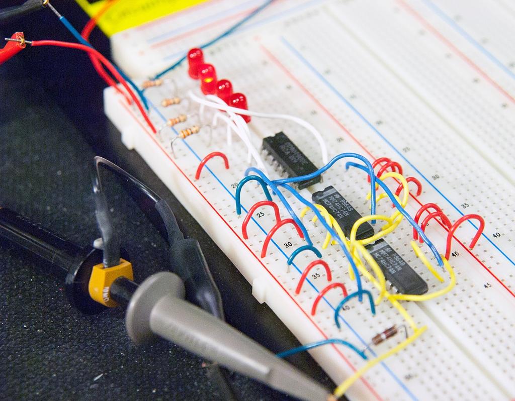
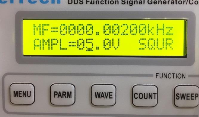
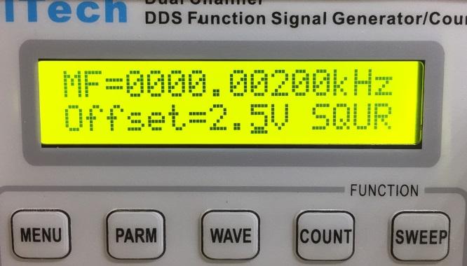
3 Page 3 Exercise 4-3: Four Bit Binary Counter with Buffer Drivers Objective: To demonstrate asynchronous counting with CMOS flip flops, and driving LEDS with a CMOS hex buffer, the Breadboard the following circuit and observe the LED binary counter. Set the function generator for a 5 volt square wave and amplitude offset of 2.5 volts (so that the voltage swing is 0 to 5 volts and not -2.5 to 2.5 volts). Set the frequency to 20 hertz. (See the photos below.) Remember to also power the ICs. V CC and V DD (diagrams below) go to the plus 5 volt rail, and GND and V SS to the ground rail Does the circuit count the pulses correctly? (yes or no) Images courtesy of Fairchild Semiconductor


4 Page 4
5 Page 5 4-4: Design a Circuit Board (Optional) Objective: Convert a circuit drawn in Multisim into a circuit board using the Ultiboard software. Open the Multisim file titled Exercise 4-6: A 4-Bit Binary Counter Circuit Board. (If this has not been previously distributed to you, request the file by . You can purchase Multisim online from National Instruments for your personal computer at a low cost. The left-hand computer in the Electronic Prototyping Lab has Multisim on it.) The circuit is similar to the one you worked with earlier, but has been redrawn slightly to include a connector for inputting power and the frequency generator (below). You can accept the circuit as is, or edit it to your own wishes. For example, you could replace the function generator input with a debounced pushbutton. The resistors initially had no manufacture s footprint for placement on a circuit board. Double clicking on the part opened its feature dialog. Under the Value tab at the bottom, Edit footprint was selected, and a suitable footprint was chosen from the list available. If you were producing this board, you would want to be sure that each footprint matched the actual part you plan to use. Take a moment to inspect a part s features.


6 Next select Transfer to Ultiboard from the Transfer menu. A net list will appear as shown below: Page 6
.. All of the parts are first seen on the top.")
7 Page 7 Select OK and the circuit board layout workspace will appear. You may need to select 3D View and Spreadsheet under View menu (and slide the window to the right).. All of the parts are first seen on the top. Inside the workspace (right-hand side) drag each part into position as shown (there is no special layout).


8 Page 8 Select Start autorouter from the Autorouter menu. The software will automatically route each of the copper traces from pin to pin based on the netlist. The board has now been populated and pins routed as specified in the netlist. You can use your mouse to rotate the board and visualize the traces underneath. Save your work and quit Ultiboard and Multisim.

.")
9 Page 9 To have this board manufactured you must export the file with relevant information concerning the physical properties of the copper clad board, silk screen layer, and even the holes through the board (vias). The export dialog is as follows: End of Digital Electronics Exercises
Lab 4: Digital Electronics BMEn 2151 Introductory Medical Device Prototyping Prof. Steven S. Saliterman
 Lab 4: Digital Electronics BMEn 2151 Introductory Medical Device Prototyping Prof. Steven S. Saliterman Exercise 4-1: Familiarization with Lab Box Contents & Reference Books 4-1-1 CMOS Cookbook (In the
Finite State Machine Lab
 Finite State Machine Module: Lab Procedures Goal: The goal of this experiment is to reinforce state machine concepts by having students design and implement a state machine using simple chips and a protoboard.
Copyright 2011 R.S.R. Electronics, Inc. All rights reserved. 04/11. Ver. 1.0web
 For XILINX WebPack Copyright 2011 R.S.R. Electronics, Inc. All rights reserved. 04/11 Ver. 1.0web 1 Table of Contents 1.0 INTRODUCTION...3 2.0 GENERAL DESCRIPTION...5 3.0 BRIEF DESCRIPTION Of PLDT-3 BOARD...6
Drexel University Electrical and Computer Engineering Department ECE 200 Intelligent Systems Spring Lab 1. Pencilbox Logic Designer
 Lab 1. Pencilbox Logic Designer Introduction: In this lab, you will get acquainted with the Pencilbox Logic Designer. You will also use some of the basic hardware with which digital computers are constructed
ECE 270 Lab Verification / Evaluation Form. Experiment 1
 ECE 70 Lab Verification / Evaluation Form Experiment Evaluation: IMPORTANT! You must complete this experiment during your scheduled lab period. All work for this experiment must be demonstrated to and
E85: Digital Design and Computer Engineering Lab 1: Electrical Characteristics of Logic Gates
 E85: Digital Design and Computer Engineering Lab 1: Electrical Characteristics of Logic Gates Objective The purpose of this lab is to become comfortable with logic gates as physical objects, to interpret
Discharge by touching: BNC coax shield, outlet metal cover plate, wire connected to GND
 Step-down transformer Very High Voltage Very Low Current Lower Voltage, 110V Power Station Grounding contact (3rd wire) Faulty wiring makes box hot!! Current path splits: 1) to ground (mostly) 2) through
PIC Dev 14 Through hole PCB Assembly and Test Lab 1
 Name Lab Day Lab Time PIC Dev 14 Through hole PCB Assembly and Test Lab 1 Introduction: The Pic Dev 14 is a simple 8-bit Microchip Pic microcontroller breakout board for learning and experimenting with
Touch Control Switch + - R6 R4 R8 R7 CAT# Grading. Assembly Instructions by Earl D. Gates SUNY Oswego Fall Conference 2007.
 Grading Name: Class: Shade the number in column A that reflects your ability. In column B, have your instructor do the same. 6. Ability to identify and use basic electronic assembly tools. 8. Ability to
Lab 9 Introduction to Multisim & Ultiboard
 Lab 9 Introduction to Multisim & Ultiboard In this lab you will be utilizing your understanding of circuit generation/testing in Multisim in order to create the final project (figure 1), a TinyMatrix pendant.
Introduction to NI Multisim & Ultiboard
 George Washington University School of Engineering and Applied Science Electrical and Computer Engineering Department Introduction to NI Multisim & Ultiboard Dr. Amir Aslani 8/20/2017 2 Outline Design
Introduction to Electronics Workbench
 Introduction to Electronics Workbench Electronics Workbench (EWB) is a design tool that provides you with all the components and instruments to create board-level designs on your PC. The user interface
Copyright 2008, 2009 Grandad s Electronics Seattle, Washington, USA. INSTRUCTION MANUAL Model XTAL1. XTAL1 (assembled)
") Copyright 2008, 2009 Grandad s Electronics Seattle, Washington, USA INSTRUCTION MANUAL Model XTAL1 XTAL1 (assembled) 1 XTAL1 Manual, 12/23/2008 Assembly Instructions This kit assumes that the purchaser
Copyright 2008, 2009 Grandad s Electronics Seattle, Washington, USA INSTRUCTION MANUAL Model XTAL1 XTAL1 (assembled) 1 XTAL1 Manual, 12/23/2008 Assembly Instructions This kit assumes that the purchaser
Exercise 1. Section 2. Working in Capture
 Exercise 1 Section 1. Introduction In this exercise, a simple circuit will be drawn in OrCAD Capture and a netlist file will be generated. Then the netlist file will be read into OrCAD Layout. In Layout,
10-MINUTE TUTORIAL DIGITAL LOGIC CIRCUIT MODELING AND SIMULATION WITH MULTISIM
 1-MINUTE TUTORIAL DIGITAL LOGIC CIRCUIT MODELING AND SIMULATION WITH MULTISIM Multisim is a schematic capture and simulation program for analog, digital and mixed analog/digital circuits, and is one application
Intro to Multisim & Ultiboard
 Intro to Multisim & Ultiboard (Lab by Wayne Stanton) Note: This document was written for version 13.0 of Multisim and Ultiboard. Note: A grade for this lab will be applied upon receipt of the project file.
EECS 140 Laboratory Exercise 4 3-to-11 Counter Implementation
 EECS 140 Laboratory Exercise 4 3-to-11 Counter Implementation 1. Objectives A. To apply knowledge of combinatorial design. B. Gain expertise in designing and building a simple combinatorial circuit This
GEORGIA INSTITUTE OF TECHNOLOGY School of Electrical and Computer Engineering ECE 2020 Fall 2017 Lab #1: Digital Logic Module
 GEORGIA INSTITUTE OF TECHNOLOGY School of Electrical and Computer Engineering ECE 2020 Fall 2017 Lab #1: Digital Logic Module GOAL To introduce the physical implementation of digital logic circuits including
CS4141 IDL Notes. I. Quick Overview of IDL Prototyping Unit
 CS4141 IDL Notes IDL-800 Prototyping System The IDL-800 logic panels are powerful tools for any logic designer. They enable a wide range of IC s to be used in a breadboard experiment. I. Quick Overview
This section contains a tutorial that introduces you to Multisim and its many functions.
 GETTING STARTED GUIDE NI Circuit Design Suite This document contains the following step-by-step tutorials: Multisim Tutorial Multisim is the schematic capture and simulation program designed for schematic
1. Working with PSpice:
 Applied Electronics, Southwest Texas State University, 1, 13 1. Working with PSpice: PSpice is a circuit simulator. It uses the Kirchhoff s laws and the iv-relation of the used components to calculate
HW #5: Digital Logic and Flip Flops
 HW #5: Digital Logic and Flip Flops This homework will walk through a specific digital design problem in all its glory that you will then implement in this weeks lab. 1 Write the Truth Table (10 pts) Consider
Experiment 1 Electrical Circuits Simulation using Multisim Electronics Workbench: An Introduction
 Experiment 1 Electrical Circuits Simulation using Multisim Electronics Workbench: An Introduction Simulation is a mathematical way of emulating the behavior of a circuit. With simulation, you can determine
ENEE245 Digital Circuits and Systems Lab Manual
 ENEE245 Digital Circuits and Systems Lab Manual Department of Engineering, Physical & Computer Sciences Montgomery College Modified Fall 2017 Copyright Prof. Lan Xiang (Do not distribute without permission)
Digital Circuits. Page 1 of 5. I. Before coming to lab. II. Learning Objectives. III. Materials
 I. Before coming to lab Read this handout and the supplemental. Also read the handout on Digital Electronics found on the course website. II. Learning Objectives Using transistors and resistors, you'll
Programmable Logic Design Techniques I
 PHY 440 Lab14: Programmable Logic Design Techniques I The design of digital circuits is a multi-step process. It starts with specifications describing what the circuit must do. Defining what a circuit
Introduction to Multisim Schematic Capture and SPICE Simulation
 Introduction to Multisim Schematic Capture and SPICE Simulation By: Janell Rodriguez and Erik Luther Online: This selection and arrangement of content as a collection
This presentation will..
 Component Identification: Digital Introduction to Logic Gates and Integrated Circuits Digital Electronics 2014 This presentation will.. Introduce transistors, logic gates, integrated circuits (ICs), and
Lesson 9: Advanced Placement Techniques
 9 Lesson 9: Advanced Placement Techniques Learning Objectives In this lesson you will: Turn ratsnests on and off to selectively place components Use interactive swapping for pins and gates Apply advanced
ENEE245 Digital Circuits and Systems Lab Manual
 ENEE245 Digital Circuits and Systems Lab Manual Department of Engineering, Physical & Computer Sciences Montgomery College Version 1.1 Copyright Prof. Lan Xiang (Do not distribute without permission) 1
Programmable Logic Design I
 Programmable Logic Design I Introduction In labs 11 and 12 you built simple logic circuits on breadboards using TTL logic circuits on 7400 series chips. This process is simple and easy for small circuits.
Lab #2: Building the System
 Lab #: Building the System Goal: In this second lab exercise, you will design and build a minimal microprocessor system, consisting of the processor, an EPROM chip for the program, necessary logic chips
2008 년안산일대디지털정보통신학과 CAD 강의용자료 PADS 2007
 2008 년안산일대디지털정보통신학과 CAD 강의용자료 PADS 2007 1 Learning the PADS User Interface What you will learn: Modeless Commands Panning & Zooming Object Selection Methods Note: This tutorial will use PADS Layout to
Experiment 9: Binary Arithmetic Circuits. In-Lab Procedure and Report (30 points)
") ELEC 2010 Laboratory Manual Experiment 9 In-Lab Procedure Page 1 of 7 Experiment 9: Binary Arithmetic Circuits In-Lab Procedure and Report (30 points) Before starting the procedure, record the table number
ELEC 2010 Laboratory Manual Experiment 9 In-Lab Procedure Page 1 of 7 Experiment 9: Binary Arithmetic Circuits In-Lab Procedure and Report (30 points) Before starting the procedure, record the table number
Lab 16: Data Busses, Tri-State Outputs and Memory
 Lab 16: Data Busses, Tri-State Outputs and Memory UC Davis Physics 116B Rev. 0.9, Feb. 2006 1 Introduction 1.1 Data busses Data busses are ubiquitous in systems which must communicate digital data. Examples
EECE 2411/2211-Introduction to Electrical and Computer Engineering Lab. Lab 3
 EECE 2411/2211-Introduction to Electrical and Computer Engineering Lab Lab 3 Building Multi-Gate Logic Circuits Introduction: In this lab we will look at combining the simple logic gates we used in the
ECEN 1400, Introduction to Analog and Digital Electronics
 ECEN 1400, Introduction to Analog and Digital Electronics How to create circuit boards using multisim and ultiboard This document walks you through the steps to make a working printed circuit board (PCB).
Electronics & Control
 Engineering Science Electronics & Control Logic Page 2 Introduction Electronic circuits can be use to control a huge variety of systems but in each case there are IN- PUTS, PROCESSES and OUTPUTS. In this
A B A+B
 ECE 25 Lab 2 One-bit adder Design Introduction The goal of this lab is to design a one-bit adder using programmable logic on the BASYS board. Due to the limitations of the chips we have in stock, we need
Table of Contents. Introductory Material
 Table of Contents Introductory Material 0.1 Equipment Intoduction 1 breadboard area stimulator board 2 The Board of Education The TDS 340 oscilloscope 0.2 Getting Started with the Micro-controller The
SCHEMATIC1 SCHEMATIC2 SCHEMATIC1 SCHEMATIC2 SCHEMATIC3 PAGE1 PAGE2 PAGE3 PAGE1 PAGE1 PAGE2 PAGE1 PAGE1 PAGE2
 An OrCAD Tutorial Dr. S.S.Limaye 1. Introduction OrCAD is a suite of tools from Cadence company for the design and layout of printed circuit boards (PCBs). This is the most popular tool in the industry.
- create new schematic to the new project, PCB design begins with a schematic diagram, which present how components are connected
 Eagle 8.x tutorial - create a new project, Eagle designs are organized as projects - create new schematic to the new project, PCB design begins with a schematic diagram, which present how components are
Name EET 1131 Lab #14 Random Access Memory
 Name EET 1131 Lab #14 Random Access Memory 7489 RAM Chip The 7489 is a TTL random access memory chip. It is organized as a 16 x 4 RAM. To be sure you understand what this means, answer the following questions:
OrCad & Spice Tutorial By, Ronak Gandhi Syracuse University
 OrCad & Spice Tutorial By, Ronak Gandhi Syracuse University Brief overview: OrCad is a suite of tools from Cadence for the design and layout of circuit design and PCB design. We are currently using version
PIC Dev 14 Surface Mount PCB Assembly and Test Lab 1
 Name Lab Day Lab Time PIC Dev 14 Surface Mount PCB Assembly and Test Lab 1 Introduction: The Pic Dev 14 SMD is a simple 8-bit Microchip Pic microcontroller breakout board for learning and experimenting
Infrared Add-On Module for Line Following Robot
 1 Infrared Add-On Module for Line Following Robot January 3, 2015 Jeffrey La Favre The infrared add-on module allows multiple line following robots to operate on the same track by preventing collisions
EXPERIMENT 6. CMOS INVERTERS AND CMOS LOGIC CIRCUITS
 EXPERIMENT 6. CMOS INVERTERS AND CMOS LOGIC CIRCUITS I. Introduction I.I Objectives In this experiment, you will analyze the voltage transfer characteristics (VTC) and the dynamic response of the CMOS
PART 1. Simplification Using Boolean Algebra
 Name EET 1131 Lab #5 Logic Simplification Techniques OBJECTIVES: Upon completing this lab, you ll be able to: 1) Obtain the experimental truth table of a logic circuit. 2) Use Boolean algebra to simplify
EE 210 Lab Assignment #2: Intro to PSPICE
 EE 210 Lab Assignment #2: Intro to PSPICE ITEMS REQUIRED None Non-formal Report due at the ASSIGNMENT beginning of the next lab no conclusion required Answers and results from all of the numbered, bolded
Orcad Layout Plus Tutorial
 Orcad Layout Plus Tutorial Layout Plus is a circuit board layout tool that accepts a layout-compatible circuit netlist (ex. from Capture CIS) and generates an output layout files that suitable for PCB
MAKE A PRINTED-CIRCUIT-BOARD (PCB) FOR YOUR ELECTRONIC DEVICE 11/10/2017 CLIFF CURRY
 FOR YOUR ELECTRONIC DEVICE 11/10/2017 CLIFF CURRY") MAKE A PRINTED-CIRCUIT-BOARD (PCB) FOR YOUR ELECTRONIC DEVICE 11/10/2017 CLIFF CURRY PART ONE: AN INTRODUCTION TO PRINTED CIRCUIT BOARDS. WHAT ARE THEY, AND HOW DOES ONE SPECIFY THEM TO GET WHAT ONE WANTS?
MAKE A PRINTED-CIRCUIT-BOARD (PCB) FOR YOUR ELECTRONIC DEVICE 11/10/2017 CLIFF CURRY PART ONE: AN INTRODUCTION TO PRINTED CIRCUIT BOARDS. WHAT ARE THEY, AND HOW DOES ONE SPECIFY THEM TO GET WHAT ONE WANTS?
Introduction to LogicWorks (Version 5) by: Kevin Su
 by: Kevin Su") Introduction to LogicWorks (Version 5) January 24, 2005 by: Kevin Su 0. INTRODUCTION These notes are meant as a supplement for students taking CS 2513 (Computer Organizaition I ), especially for those
Introduction to LogicWorks (Version 5) January 24, 2005 by: Kevin Su 0. INTRODUCTION These notes are meant as a supplement for students taking CS 2513 (Computer Organizaition I ), especially for those
LDR_Light_Switch1 -- Overview
 LDR_Light_Switch1 -- Overview OBJECTIVES After performing this lab exercise, learner will be able to: Understand the functionality of Light Dependent Resistor (LDR) Use LDR (Light Dependent Resistor) to
The PUMPKIN LIGHT LED
 The PUMPKIN LIGHT LED PUMPKIN LIGHT LED By Mark McCuller Email: mcculler@mail.com DESIGN SUMMARY The PUMPKIN LIGHT LED By: Mark McCuller The Pumpkin Light LED is a battery-powered device that illuminates
Tutorial 3: Using the Waveform Viewer Introduces the basics of using the waveform viewer. Read Tutorial SIMPLIS Tutorials SIMPLIS provide a range of t
 Tutorials Introductory Tutorials These tutorials are designed to give new users a basic understanding of how to use SIMetrix and SIMetrix/SIMPLIS. Tutorial 1: Getting Started Guides you through getting
Intro to Logic Gates & Datasheets. Intro to Logic Gates & Datasheets. Introduction to Integrated Circuits. TTL Vs. CMOS Logic
 Intro to Logic Gates & Datasheets Digital Electronics Intro to Logic Gates & Datasheets This presentation will Introduce integrated circuits (ICs). Present an overview of : Transistor-Transistor Logic
Intro to Logic Gates & Datasheets. Digital Electronics
 Intro to Logic Gates & Datasheets Digital Electronics Intro to Logic Gates & Datasheets This presentation will Introduce integrated circuits (ICs). Present an overview of : Transistor-Transistor Logic
Breakout Card For Z50Bus User Guide
 Breakout Card For Z50Bus User Guide For card: SC117 version 1.0 Design and Documentation by Stephen C Cousins Edition 1.0.0 CONTENTS OVERVIEW...2 PRINTED CIRCUIT BOARD... 4 SCHEMATIC... 5 WHAT YOU NEED...6
NI Circuit Design Suite
 RELEASE NOTES NI Circuit Design Suite Version 10.0 Contents These release notes contain system requirements for NI Circuit Design Suite 10.0, and information about product tiers, new features, documentation
ARM: Microcontroller Touch-switch Design & Test (Part 1)
") ARM: Microcontroller Touch-switch Design & Test (Part 1) 2 nd Year Electronics Lab IMPERIAL COLLEGE LONDON v2.00 Table of Contents Equipment... 2 Aims... 2 Objectives... 2 Recommended Timetable... 2 Introduction
ARM: Microcontroller Touch-switch Design & Test (Part 1) 2 nd Year Electronics Lab IMPERIAL COLLEGE LONDON v2.00 Table of Contents Equipment... 2 Aims... 2 Objectives... 2 Recommended Timetable... 2 Introduction
Massachusetts Institute of Technology Department of Electrical Engineering and Computer Science Introductory Digital Systems Laboratory
 Massachusetts Institute of Technology Department of Electrical Engineering and Computer Science 6.111 -- Introductory Digital Systems Laboratory NUBUS LABORATORY KIT For your pleasure and convenience,
University of Kansas EECS Circuit Board Fabrication Tutorial for 212 Lab
 University of Kansas EECS Circuit Board Fabrication Tutorial for 212 Lab Preparing For Export... 1 Assigning Footprints... 1 Recommended Footprints... 2 No Connects... 3 Design Rules Check... 3 Create
Using OrCAD Layout Plus A Simple Guide
 Using OrCAD Layout Plus A Simple Guide Written by Jose Cabral September 2006 Revised by Nithin Raghunathan 1 SKETCH THE CIRCUIT YOU WISH TO LAYOUT SKETCH THE LAYOUT COM J1 OUTPUT +12 COM -12 COM INPUT
Complete Tutorial (Includes Schematic & Layout)
") Complete Tutorial (Includes Schematic & Layout) Download 1. Go to the "Download Free PCB123 Software" button or click here. 2. Enter your e-mail address and for your primary interest in the product. (Your
Complete Tutorial (Includes Schematic & Layout) Download 1. Go to the "Download Free PCB123 Software" button or click here. 2. Enter your e-mail address and for your primary interest in the product. (Your
Digital Circuits 1: Binary, Boolean, and Logic
 Digital Circuits 1: Binary, Boolean, and Logic Created by Dave Astels Last updated on 2018-03-22 04:13:46 PM UTC Guide Contents Guide Contents Introduction Number systems Decimal: base 10 Binary Octal
Construction Construction Instructions
 Semi-Virtual Diskette SVD Construction Construction Instructions PCB version 2.0 September 2004 Eric J. Rothfus Table of Contents Table of Contents... i Parts List...1 Construction Overview...5 PCB Construction...
Physics 430 Laboratory Manual Rev.: 2004 Sept. 29
 LAB 3 First steps with a micro-controller Input Output voltage levels, Loop Timing, and Connecting LEDs and Switches Suggested reading: What is A Microcontroller, A Student Guide, by Parallax, Inc., Chapters
SOUTHERN POLYTECHNIC S. U.
 SOUTHERN POLYTECHNIC S. U. ECET 1012 Laboratory Exercise #4 ELECTRICAL & COMPUTER ENGINEERING TECHNOLOGY Introduction to PSpice Name Lab Section Date Overview: This laboratory experiment introduces the
Introduction to PSpice
 Introduction to PSpice Simulation Software 1 The Origins of SPICE In the 1960 s, simulation software begins CANCER Computer Analysis of Nonlinear Circuits, Excluding Radiation Developed at the University
Simulation examples Chapter overview
 Simulation examples 2 Chapter overview The examples in this chapter provide an introduction to the methods and tools for creating circuit designs, running simulations, and analyzing simulation results.
Digital Logic Design Exercises. Assignment 1
 Assignment 1 For Exercises 1-5, match the following numbers with their definition A Number Natural number C Integer number D Negative number E Rational number 1 A unit of an abstract mathematical system
Anadigm FPAA Solutions Training Class III
 Anadigm FPAA Solutions Training Class III Agenda Learning Goals Evaluation board components Board architecture Power connection COM connection Output connection Development board Verify proper connection
Lab 0: Wire Wrapping Project: Counter Board
 Lab 0: Wire Wrapping Project: Counter Board September 3, 2008 In this experiment, you will build a simple counter circuit that can be plugged into your breadboard. It will provide a set of TTL output signals
ES 210 Lab. Jack Ou, Ph.D.
 ES 210 Lab Jack Ou, Ph.D. April 30, 2013 2 Contents 1 555 Timer 5 1.1 A Monostable Circuit...................... 5 1.1.1 Parts............................ 5 1.1.2 A Monostable Circuit..................
ESE 570 Cadence Lab Assignment 2: Introduction to Spectre, Manual Layout Drawing and Post Layout Simulation (PLS)
") ESE 570 Cadence Lab Assignment 2: Introduction to Spectre, Manual Layout Drawing and Post Layout Simulation (PLS) Objective Part A: To become acquainted with Spectre (or HSpice) by simulating an inverter,
ESE 570 Cadence Lab Assignment 2: Introduction to Spectre, Manual Layout Drawing and Post Layout Simulation (PLS) Objective Part A: To become acquainted with Spectre (or HSpice) by simulating an inverter,
Extreme makeover for the Nucleus Model 500 Geiger Counter by Mark McLaughlin
 Extreme makeover for the Nucleus Model 500 Geiger Counter by Mark McLaughlin Figure 1: The Nucleus Model 500 Geiger Counter with its makeover. The Geiger counters used in the introductory Physics labs
PAD ANALOG / DIGITAL TRAINER OPERATOR S MANUAL
 PAD - 234 ANALOG / DIGITAL TRAINER OPERATOR S MANUAL Rev. 7/94 GENERAL OPERATING PROCEDURES 1. This manual should be read thoroughly before engaging in any experimentation. 2. As a general rule, NEVER
External and Flash Memory
 Digital Signal Processing: Laboratory Experiments Using C and the TMS320C31 DSK Rulph Chassaing Copyright 1999 John Wiley & Sons, Inc. Print ISBN 0-471-29362-8 Electronic ISBN 0-471-20065-4 C External
Introduction to MATLABs Data Acquisition Toolbox, the USB DAQ, and accelerometers
 Introduction to MATLABs Data Acquisition Toolbox, the USB DAQ, and accelerometers This week we will start to learn the software that we will use through the course, MATLAB s Data Acquisition Toolbox. This
COS 116 The Computational Universe Laboratory 7: Digital Logic I
 COS 116 The Computational Universe Laboratory 7: Digital Logic I In this lab you ll construct simple combinational circuits in software, using a simulator, and also in hardware, with a breadboard and silicon
Physics 120/220 Lab Equipment, Hints & Tips
 Physics 120/220 Lab Equipment, Hints & Tips Solderless Breadboard... 2 Power supply... 4 Multimeters... 5 Function generator... 5 Oscilloscope... 6 10X probe... 7 Resistor color code... 7 Components...
TUTORIAL SESSION Technical Group Hoda Najafi & Sunita Bhide
 TUTORIAL SESSION 2014 Technical Group Hoda Najafi & Sunita Bhide SETUP PROCEDURE Start the Altium Designer Software. (Figure 1) Ensure that the Files and Projects tabs are located somewhere on the screen.
Cadence Tutorial A: Schematic Entry and Functional Simulation Created for the MSU VLSI program by Andrew Mason and the AMSaC lab group.
 Cadence Tutorial A: Schematic Entry and Functional Simulation Created for the MSU VLSI program by Andrew Mason and the AMSaC lab group. Revision Notes: Aug. 2003 update and edit A. Mason add intro/revision/contents
Hands-on Lab 2: LabVIEW NI-DAQ Basics 2
 Hands-on Lab 2: LabVIEW NI-DAQ Basics 2 Recall that the final objective is position regulation using computer-controlled state feedback. Computer control requires both software, like LabVIEW and hardware,
BG1B Universal Gate Drive Prototype Board
 BG1B Universal Gate Drive Prototype Board Description: The BG1B is a single channel gate drive circuit board for high power IGBT modules. The BG1B utilizes Powerex hybrid gate drivers and DC-to-DC converters
EE 314 Spring 2003 Microprocessor Systems. Parallel Printer Port Use and Digital-to-Analog Conversion
 EE 314 Spring 2003 Microprocessor Systems Laboratory Project #6 Parallel Printer Port Use and Digital-to-Analog Conversion Important Note Concerning Equipment. This is the first lab that has required the
Lab 16: Tri-State Busses and Memory U.C. Davis Physics 116B Note: We may use a more modern RAM chip. Pinouts, etc. will be provided.
 Lab 16: Tri-State Busses and Memory U.C. Davis Physics 116B Note: We may use a more modern RAM chip. Pinouts, etc. will be provided. INTRODUCTION In this lab, you will build a fairly large circuit that
An Introduction to the Logic. Silicon Chips
 An Introduction to the Logic of Silicon Chips Here is a photo of a typical silicon chip, taken alongside the tip of my little finger. Modern chips can be made a good deal smaller than the one shown - just
Outline for Today. Lab Equipment & Procedures. Teaching Assistants. Announcements
 Announcements Homework #2 (due before class) submit file on LMS. Submit a soft copy using LMS, everybody individually. Log onto the course LMS site Online Assignments Homework 2 Upload your corrected HW2-vn.c
Building and using JasperMIDI
 Building and using JasperMIDI Table of Contents Introduction... Bill Of Materials... 2 Building Choices... 3 Construction... 4 Installing in a Jasper enclosure... 5 Standalone use... 6 Using JasperMIDI...
LushOne Inca Synth Module Build Instructions
 LushOne Inca Synth Module Build Instructions Getting started If you can build the LushOne base module then then building the Inca should be easy Remember: Accuracy and neatness is more important than speed
Lab Manual for COE 203: Digital Design Lab
 Lab Manual for COE 203: Digital Design Lab 1 Table of Contents 1. Prototyping of Logic Circuits using Discrete Components...3 2. Prototyping of Logic Circuits using EEPROMs...9 3. Introduction to FPGA
Tektronix DPO Demo 1 Board Instruction Manual
 xx ZZZ Tektronix DPO Demo 1 Board Instruction Manual www.tektronix.com *P071253900* 071-2539-00 Copyright Tektronix. All rights reserved. Licensed software products are owned by Tektronix or its subsidiaries
University of California at Berkeley College of Engineering Department of Electrical Engineering and Computer Science. EECS 150 Spring 2000
 University of California at Berkeley College of Engineering Department of Electrical Engineering and Computer Science EECS 150 Spring 2000 Lab 1 Introduction to Xilinx Design Software 1 Objectives In this
Programmable Logic Design I
 Programmable Logic Design I Read through each section completely before starting so that you have the benefit of all the directions. Put on a grounded wrist strap (cf. Getting Started) before touching
Creating Verilog Tutorial Netlist Release Date: 01/13/2005(Version 2)
") Creating Verilog Tutorial 2-1 - Creating a verilog netlist for a schematic: The verilog netlist is necessary for automatic layout (placement and routing) tools. It contains information about the I/O pins
Creating Verilog Tutorial 2-1 - Creating a verilog netlist for a schematic: The verilog netlist is necessary for automatic layout (placement and routing) tools. It contains information about the I/O pins
Terasic DE0 Field Programmable Gate Array (FPGA) Development Board
 Development Board") Lecture FPGA-01 DE0 FPGA Development Board and Quartus II 9.1 FPGA Design Software Terasic DE0 Field Programmable Gate Array (FPGA) Development Board 1 May 16, 2013 3 Layout and Components of DE0 May 16,
Lecture FPGA-01 DE0 FPGA Development Board and Quartus II 9.1 FPGA Design Software Terasic DE0 Field Programmable Gate Array (FPGA) Development Board 1 May 16, 2013 3 Layout and Components of DE0 May 16,
PCB-STM32-F3U. Development baseboard for the STMicro Discovery-F3 module (STMicro part# STM32F3DISCOVERY)
") PCB-STM32-F3U Development baseboard for the STMicro Discovery-F3 module (STMicro part# STM32F3DISCOVERY) Part Number: PCB-STM32-F3U (unpopulated PCB with Discovery module sockets, no other parts) STM32-F3U
PCB-STM32-F3U Development baseboard for the STMicro Discovery-F3 module (STMicro part# STM32F3DISCOVERY) Part Number: PCB-STM32-F3U (unpopulated PCB with Discovery module sockets, no other parts) STM32-F3U
Development Kit Manual DK-114N-1 and DK-114N-3
 Development Kit Manual DK-114N-1 and DK-114N-3 Overview Big Chip LEDs from Luminus Devices have been designed from the ground up to enable a new class of illumination and projection systems. Benefiting
Chapter 9. Input/Output (I/O) Ports and Interfacing. Updated: 3/13/12
 Ports and Interfacing. Updated: 3/13/12") Chapter 9 Input/Output (I/O) Ports and Interfacing Updated: 3/13/12 Basic Concepts in I/O Interfacing and PIC18 I/O Ports (1 of 2) I/O devices (or peripherals) such as LEDs and keyboards are essential
Chapter 9 Input/Output (I/O) Ports and Interfacing Updated: 3/13/12 Basic Concepts in I/O Interfacing and PIC18 I/O Ports (1 of 2) I/O devices (or peripherals) such as LEDs and keyboards are essential