TCP/IP Base Board Setup Instructions (JGS_ETH24_BASE)
|
|
|
- Joshua Booker
- 5 years ago
- Views:
Transcription

1 TCP/IP Base Board Setup Instructions (JGS_ETH24_BASE) Actual Size Image 2.1mm Power Jack RJ45 MagJack ICSP Programming Connector 3.5mm Stereo Jack for Serial I/O 4 8 pin headers for external connections Board Description and Features The JGS_ETH24_BASE board is an embedded TCP/IP 10 BaseT network module designed to work with the Microchip TCP/IP stack. The board consists of the following components: Microchip PIC24HJ128GP MIPS microcontroller. Microchip ENC28J60 10 BaseT Ethernet interface. SST (now Microchip) 2 or 4 MByte Serial Flash memory. Microchip 25AA02E48 MAC address chip provides universally unique MAC address. MAX3232 serial interface provides 2 serial ports. 3.5mm TRS (stereo) jack provides access to one serial port. 2.1mm Power Jack for connecting a 5 volt power supply. Onboard voltage regulator provides 3.3V to the components. RJ45 MagJack connector for Ethernet connection via CAT 5/6 cable. 4 8 pin 0.1 pitch headers provide access to 5V, 3.3V, Gnd, MCLR, second serial port and 26 I/O lines. Of the microprocessor s on board peripherals, only SPI1 and Timer1 are reserved, all others are available. ICSP programming support. Pads for adding a 32khz watch crystal for RTCC support. While the MagJack has LED link and activity indicators, additional LEDs on the board makes them more visible. Pads for 0 ohm resistors for connecting the second serial port. On board power indicator. Test point for measuring current at the 3.3V rail. All on a 3.5 by 2 board. Includes instructions for use with Microchip TCP/IP stack. TCP-IP Base Board Setup.docx September 2011

 If you don t have a serial cable to monitor the board startup and see the assigned IP address, use the MicrochipEthernetDiscover utility to find the IP address.")

2 Package Contents 1 JGS_ETH24_BASE board, assembled, tested and loaded with software. 1 Printed copy of the instructions The following files: o TCP-IP Base Board Setup.pdf this document o HWP JGS_ETH24_BASE.h o TCPIP JGS_ETH24_BASE.h o MainDemo.h o MainDemo.c o pps.h o SMTPDemo.c o JGS-ETH24-BASE.hex o TCPIPConfig.h o HardwareProfile.h The board comes with a version of the Microchip TCPIP Demo App loaded. Connect the serial, power and Ethernet cables and it s ready to go. (The default baud rate is 38,400.) If you don t have a serial cable to monitor the board startup and see the assigned IP address, use the MicrochipEthernetDiscover utility to find the IP address. This utility can be found in the C:\Microchip Solutions v \Microchip\TCPIP Stack\Utilities directory. Then, direct a browser to the IP address of the board to see the embedded web server application running. The default setup of the board can have LEDs connected to pins RB4, RA4 and RA9, and pushbuttons connected to pins RC3 and RC4. The LEDs should be connected to ground via appropriate resistors. The normally open pushbuttons should also be connected to ground. These pins are all located on the J3 header, next to the 5V, Gnd and 3.3V pins. For my testing I fashioned a testing fixture out of some spare parts. A sample, along with the circuit diagram, are shown below: TCP-IP Base Board Setup.docx September 2011
3 Microchip TCP/IP Stack Configuration In order to follow the instructions below, you will need to download and install the following software from Microchip on your computer. These instructions assume all the applications and libraries have been installed in their default locations. The version numbers refer to the ones I used. Microchip MPLAB IDE version ( ) Microchip C30 Compiler version ( ) You must register with the site to download this. The free and evaluation versions work fine. Microchip Application Libraries v ( ) which includes the TCP/IP Stack version Please note that directories have been reorganized in the TCP/IP stack in each of the most recent versions and may therefore be reorganized again. The instructions below apply to the versions listed above but should work with other versions as well, with some adjustment. Microchip Application Libraries Help Files This is important because the documentation for the TCP/IP stack is part of this. The TCP/IP stack and supporting utilities are complex and anyone using the stack should go through this documentation. You will also need: Microchip PICKit2 or similar device for loading hex code via the ICSP connection. Be sure to load any associated software. Serial cable consisting of a 3.5mm TRS (stereo) plug at one end and a DB 9 Female connector at the other. Tip connects to pin 2 (TX from board), Ring connects to pin 3 (RX from board), and Sleeve connects to pin 5 (Ground). Plug the DB 9 connector into your computer s serial port or USB to Serial converter cable. Further information on TRS connectors is available here: Terminal program such as TeraTerm. ( CAT 5 cable to connect the board to your Ethernet switch. Regulated 5 volt, 500mA power supply. You can also power the board from the PICKit 2 programmer. Modified Microchip source files that accompany the JGS_ETH24_BASE board. These instructions preserve the original project structure so that there is the least amount of difference between the Demo App for this board and the original. This will help you in learning how the projects and their files are organized. These instructions also assume you know how to use the MPLAB IDE. Working within the C:\Microchip Solutions v \tcpip directory do the following: 1. Make a copy of the Demo App directory and rename Demo App. at the beginning sorts the directory to the top of the list so it s easier to find. 2. In the new directory start MPLAB with the C30-EX16_ENC28.mcp project. 3. On the Configure tab change the device to PIC24HJ128GP In the Project Build Options, MPLAB C30, General, change the Preprocessor Macros for MPLAB C30 to JGS_ETH24_BASE. 5. In the Project Build Options, MPLAB C30, Optimization, select 0 for no optimization. 6. In the Project Build Options, Directories, change the Intermediate Directory to Obj-JGS_ETH24_BASE. 7. On the Project tab save the project as JGS_ETH24_BASE. TCP-IP Base Board Setup.docx September 2011
4 o Be sure you save the project into your new directory. MPLAB remembers a project s directory, so when you switch project locations it may try to save to an old location. 8. Copy the following files to the project root directory: o MainDemo.c o MainDemo.h o pps.h o SMTPDemo.c o HardwareProfile.h o TCPIPConfig.h 9. You can clean up the project root directory by erasing all the other.mcp and.mcw files. 10. Delete all the existing files in the Configs subdirectory and copy into it the following files: o HWP JGS_ETH24_BASE.h o TCPIP JGS_ETH24_BASE.h NOTE: After doing the file cleanup you may get a warning message that some source files are not where they used to be. You can ignore this (assuming you didn t delete too much) and clean up the file list in the workspace window. 11. In the C:\Microchip Solutions v \microchip\tcpip Stack directory edit the file ENC28J60.c and comment out line 320. This will allow the CLKOUT signal to be generated to provide the clock signal for the PIC Check and/or set the baud rate you want to use for serial communications in MainDemo.h. 13. Compile the project (F10) and load the hex file onto the processor using the ICSP connection. 14. Connect a terminal program to the serial port. 15. Apply power to the board. You should see output displaying the name of the board and the IP address. If LED0 is connected, it should be flashing once per second. 16. If you built your own board or have been using some other web pages, use MPFS2.exe, also in the utilities directory, to load the Demo App web pages into the board s serial flash memory. Instructions for using the MPFS2 program are in the help file for the TCP/IP stack. The web site image file is MPFSImg2.bin which is in the project root directory. You can also reload it from the original Demo App directory. 17. Direct your browser at the IP address to display the stored web pages. Configuration The board and software are configured as follows: TIMER1 is used by the TCP/IP stack UART2 is used by the TCP/IP stack for configuration and debugging SPI1 is used to communicate with the ENC28J60, serial flash and MAC address chips SPI2 is used by the optional thermostat daughterboard for the LCD display UART1 can be assigned to pins RB14 and RB15 which in turn can be connected to the MAX3232 via optional 0 ohm jumpers at R1 and R2. The serial port RX and TX will come out at J6.7 and J6.8. The trace at R14 can be cut and a 2 pin header installed so that current at the 3.3V rail can be measured. The board has traces and pads for a 32khz watch crystal and supporting capacitors to support RTCC functions. TCP-IP Base Board Setup.docx September 2011
5 By default, the LEDs on the MAGJACK are not used. I put Link and Activity LEDs on the board because they are usually easier to see. To turn on the MAGJACK LEDs, add resistors at R5 and R6 (see the schematic for actual values.) Demonstration Modules The project directory contains a number of modules that demonstrate various capabilities, such as ping, client/server, and others, of the Microchip TCP/IP stack. If you wish to try these you may need to make some adjustments to adapt them to this hardware. Be sure to read the Microchip TCP/IP Stack documentation first. As I was researching the Microchip forums I found that there are frequent questions relating to sending with the stack. The solution to this had little to do with the stack software, rather, it had to do with the selection of a mail server. Using some of the common mail services such as Hotmail will not work due to security restrictions. When I followed the instructions and used sendmail, which is running on a web server I control, everything works as described. The included file SMTPDemo.c has been modified from the original so that an is sent when Button0 and Button1 are pressed simultaneously. You still need to modify the file with your own server and account information. UPDATE: I found that I can use my earthlink.net POP3 access information to send s from the board. Optional Ethernet Bootloader If you purchased the bootloader option then the following files were sent to you by p24hj128gp204_eble_app.gld this is a linker script that tells the compiler how much room to reserve in the processor memory for the bootloader. You must add this file to your project in the Linker Script section and then recompile the application. XTEA.exe compresses and encrypts the application hex file for loading. This is a console application and must be run in a DOS window or Command Prompt. Encrypted_ENC_loader.exe PC application that loads new applications to the hardware. Encrypted_ENC_loader.inc control file for Encrypted_ENC_loader.exe. ENC_C30.hex this is the bootloader that must be loaded onto the microprocessor via the ICSP connector. This hex file will only work with the TCP/IP Developer and Experimenter board. If you want the source code for the bootloader so you can use it with other hardware, you can buy that from Brush Electronics ( ). BE Encrypted Ethernet Bootloader System Ver 1.3.pdf manual for using the bootloader. Put all of the files in the project directory. The steps for using the Ethernet Bootloader are as follows: 1. Using the ICSP plug load ENC_C30.hex onto the target hardware, which is referred to as the LIA (LAN Interface Adapter). This only needs to be done once. 2. Compile the application, producing a new JGS_ETH24_BASE.hex. 3. Encrypt and compress the application using XTEA.exe by typing xtea JGS_ETH24_BASE.hex in a DOS window or Command Prompt. This will produce a file JGS_ETH24_BASE.cry. TCP-IP Base Board Setup.docx September 2011


6 4. Start the Encrypted_ENC_loader.exe application 5. Click the Capture Target button and reset the thermostat by going the config screen and hit save which causes a reset. Upon reset, the bootloader will run first and for 5 seconds will scan for the loader utility when it finds it and makes a connection you should see something like this in the loader: 6. Select the JGS_ETH24_BASE.cry file and click the Program button. After a while you will see a Programming Complete message. 7. Reset the hardware by clicking on the Reset LIA button. 8. All these steps should be performed promptly to avoid timeouts. 9. Restart at step 2 after revising the application. You have just reloaded the application via the Ethernet. If you have made changes to the web pages, be sure to run the MPFS2.jar utility. This is found in C:\Microchip Solutions v \microchip\tcpip Stack\Utilities as a java application so you will need to have a java runtime environment on your system. The companion utility TCPIP Discoverer.jar is useful for finding lost Microchip based TCP/IP hardware. If the Announce feature is turned on in the application, then they announce themselves to the Discoverer application. Both the Demo App and the Thermostat projects have the announce feature turned on by default. TCP-IP Base Board Setup.docx September 2011
7 Resources All the information I needed for this project I found on the Microchip web site and on the Microchip forums. The hardware information I found in the documentation for various Microchip demonstration boards and the data sheet for the ENC28J60 chip. The main information source for the TCP/IP stack is the associated help file. The first time through stack documentation is like trying to drink from a fire hose. After a while, looking at this alongside the source code for the demonstration applications, it starts to make sense. The Microchip forums helped to fill in the gaps, there are a lot of helpful and knowledgeable people there. This board is also described in the September and October 2011 issues of Nuts and Volts. The supporting website is: Pin Reference The following chart provides a reference for the various pins on the PIC24HJ128GP204 processor and how they are used. The Header Pin column identifies all the pins that are brought out to the four headers. The last column identifies pin functions unique to the TCP/IP experimenter board, the pins and headers used by the Thermostat daughterboard, and the pins used by the testing fixture, respectively. TCP-IP Base Board Setup.docx September 2011
8 PIC24HJ128GP204 Pin Reference with TCP/IP Base Assignments Name U1 Pin Number Pin Type CNxx Pullup RPxx ANxx Functions (selected) Header Pin Vdd 17,28, v J3.3 TCP/IP Base / Thermostat Pins Testing Fixture Pins (J3) Vss 6,16,29,39 GND J3.2 GND MCLR 18 J6.3 Reset button Vcap 7 RA0 19 I/O ST CN2 AN0 Vref+ J6.4 RA1 20 I/O ST CN3 AN1 Vref- J6.5 RA2 30 I/O ST CN30 OSC1, CLKI Clock input from ENC28J60 RA3 31 I/O ST CN31 OSC2, CLKO CS for MAC address chip RA4 34 I/O ST CN0 SOSCO J3.5 optional RTCC Xtal LED1 RA7 13 I/O ST PMA7 J5.8 RA8 32 I/O ST PMA8 CS for ENC28J60 RA9 35 I/O ST PMA9 J3.6 LED2 RA10 12 I/O ST PMA10 J5.7 RB0 21 I/O ST CN4 RP0 AN2 RX2, ICSP PGD RB1 22 I/O ST CN5 RP1 AN3 TX2, ICSP PGC RB2 23 I/O ST CN6 RP2 AN4 J6.6 RB3 24 I/O ST CN7 RP3 AN5 SPI1 SCK RB4 33 I/O ST CN1 RP4 SOSCI J3.4 optional RTCC Xtal LED0 RB5 41 I/O ST CN27 RP5 J4.2 Relay Heat RB6 42 I/O ST CN24 RP6 J4.3 Relay Cool RB7 43 I/O ST CN23 RP7 J4.4 LCD Backlight RB8 44 I/O ST CN22 RP8 SCL1 J4.5 LCD RS RB9 1 I/O ST CN21 RP9 SDA1 J4.6 LCD SPI2 SCK RB10 8 I/O ST CN16 RP10 J5.3 PB Off RB11 9 I/O ST CN15 RP11 J5.4 PB Heat RB12 10 I/O ST CN14 RP12 AN12 J5.5 Temp Sensor RB13 11 I/O ST CN13 RP13 AN11 J5.6 Temp Sensor RB14 14 I/O ST CN12 RP14 AN10 J6.1 optional TX1 RB15 15 I/O ST CN11 RP15 AN9 J6.2 optional RX1 RC0 25 I/O ST CN8 RP16 AN6 SPI1 SDI RC1 26 I/O ST CN9 RP17 AN7 SPI1 SDO RC2 27 I/O ST CN10 RP18 AN8 CS for Serial Flash RC3 36 I/O ST CN28 RP19 J3.7 PB Colder PB0 RC4 37 I/O ST CN25 RP20 J3.8 PB Hotter PB1 RC5 38 I/O ST CN26 RP21 J4.1 Relay Fan RC6 2 I/O ST CN18 RP22 J4.7 LCD SPI2 SDO RC7 3 I/O ST CN17 RP23 J4.8 Heartbeat LED RC8 4 I/O ST CN20 RP24 J5.1 PB Fan RC9 5 I/O ST CN19 RP25 J5.2 PB Cool TCP-IP Base Board Setup.docx September 2011
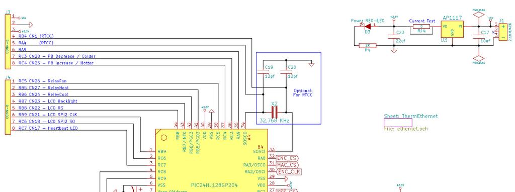
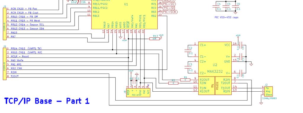
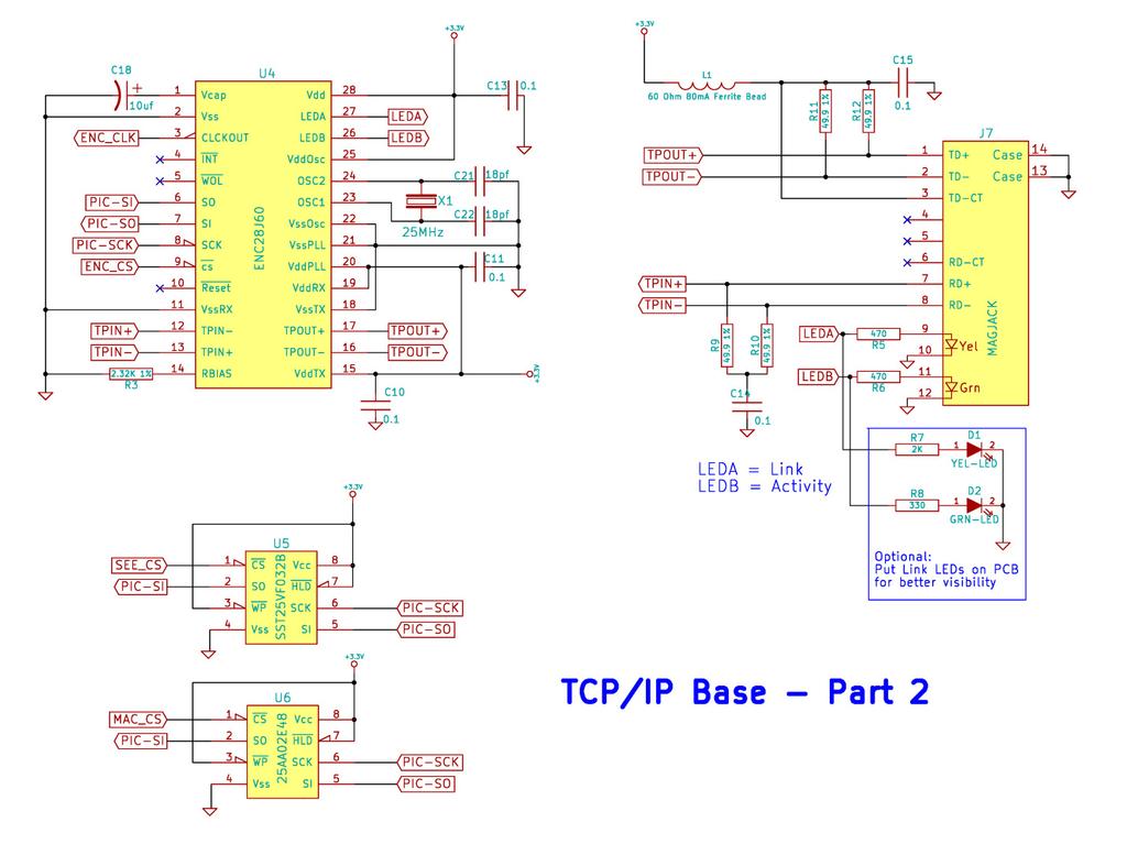
9 JGS_ETH24_BASE Circuit Diagrams TCP-IP Base Board Setup.docx September 2011
Instructionss. features: Actual Size Image. start up defaults. Sends server.) User configurable. All on - 1 -
 User configurable. All on - 1 -") Web Accessible Thermostat Instructionss Actual Size Image of Thermostat with Transparent Dark Grey Cover Description and Features The Web Accessibland Experimenter board to function. The combination provides
Web Accessible Thermostat Instructionss Actual Size Image of Thermostat with Transparent Dark Grey Cover Description and Features The Web Accessibland Experimenter board to function. The combination provides
eip-24/100 Embedded TCP/IP 10/100-BaseT Network Module Features Description Applications
 Embedded TCP/IP 10/100-BaseT Network Module Features 16-bit Microcontroller with Enhanced Flash program memory and static RAM data memory On board 10/100Mbps Ethernet controller, and RJ45 jack for network
eip-10 Embedded TCP/IP 10-BaseT Network Module Features Description Applications
 Embedded TCP/IP 10-BaseT Network Module Features 8-bit reprogrammable Microcontroller with Enhanced Flash program memory, EEPROM and Static RAM data memory On board 10Mbps Ethernet controller, and RJ45
Breeze Board. Type B. User Manual.
 Breeze Board Type B User Manual www.dizzy.co.za Contents Introduction... 3 Overview Top... 4 Overview Bottom... 5 Getting Started (USB Bootloader)... 6 Power Circuitry... 7 USB... 8 Microcontroller...
ET-PIC 24 WEB-V1. o Central Processing Unit (CPU) o System. o nanowatt Power Managed Modes. o Analog Features
 o System. o nanowatt Power Managed Modes. o Analog Features") ET-PIC 24 WEB-V1 ET-PIC 24 WEB-V1 is PIC Board Microcontroller from Microchip that uses 16 Bit No.PIC24FJ128GA008 Microcontroller for processing data and develops board. The remarkable specification of
ET-PIC 24 WEB-V1 ET-PIC 24 WEB-V1 is PIC Board Microcontroller from Microchip that uses 16 Bit No.PIC24FJ128GA008 Microcontroller for processing data and develops board. The remarkable specification of
SimPLC. User Manual.
 SimPLC User Manual www.dizzy.co.za Contents Introduction... 4 Overview Top... 5 Power Circuitry... 6 Microcontroller... 7 Real-Time Calendar and Clock (RTCC)... 7 Reset Button... 7 Oscillator Socket...
DEVBOARD3 DATASHEET. 10Mbits Ethernet & SD card Development Board PIC18F67J60 MICROCHIP
 DEVBOARD3 DATASHEET 10Mbits Ethernet & SD card PIC18F67J60 MICROCHIP Version 1.0 - March 2009 DEVBOARD3 Version 1.0 March 2009 Page 1 of 7 The DEVBOARD3 is a proto-typing board used to quickly and easily
Breeze Board. Type A. User Manual.
 Breeze Board Type A User Manual www.dizzy.co.za Contents Introduction... 3 Overview Top... 4 Overview Bottom... 5 Getting Started (Amicus Compiler)... 6 Power Circuitry... 7 USB... 8 Microcontroller...
PICado Alpha Development Board V1.0
 V1.0 Bluetooth Transceiver Module HC-05 Four onboard FET power output stage 34 freely assignable I/O pins ICSP interface 2015 Jan Ritschard, All rights reserved. V1.0 Table of Contents 1. Introduction...
Product Overview -A 16 bit Micro Experimenter for Solderless Breadboards
 Product Overview -A 16 bit Micro Experimenter for Solderless Breadboards 1.0 Introduction The 16 Bit Micro Experimenter is an innovative solderless breadboard kit solution developed by a Microchip Academic
Mega128-Net Mega128-Net Mega128 AVR Boot Loader Mega128-Net
 Mega128-Net Development Board Progressive Resources LLC 4105 Vincennes Road Indianapolis, IN 46268 (317) 471-1577 (317) 471-1580 FAX http://www.prllc.com GENERAL The Mega128-Net development board is designed
Revision: October 7, E Main Suite D Pullman, WA (509) Voice and Fax
 Voice and Fax") Cerebot 32MX4 Microchip TCP/IP Stack Reference Design Revision: October 7, 2009 215 E Main Suite D Pullman, WA 99163 (509) 334 6306 Voice and Fax Overview The Cerebot 32MX4 Microchip TCP/IP Stack Reference
Cerebot 32MX4 Microchip TCP/IP Stack Reference Design Revision: October 7, 2009 215 E Main Suite D Pullman, WA 99163 (509) 334 6306 Voice and Fax Overview The Cerebot 32MX4 Microchip TCP/IP Stack Reference
SBC44EC. Single board computer for 44 pin PLCC PICs
 Single board computer for 44 pin PLCC PICs Table of Contents 1 Introduction...2 2 Features...3 3 Expansion Connectors...4 3.1 Frontend Connectors...4 3.1.1 Connecting IDC connectors to the Frontend Connector...5
PIC 28 Pin Board Documentation. Update Version 5.0
 PIC 28 Pin Board Documentation Update 2009.10 Version 5.0 Table of Contents PIC 28 Pin Board Documentation... 1 Table of Contents... 2 Introduction... 3 Circuit Schematic... 4 The following is the Circuit
The FED PIC Flex 2 Development Boards
 The FED PIC Flex 2 Development Boards THE FED PIC Flex Development board offers a host for 28 or 40 pin devices and includes LED's, switches, transistor switches, USB interface, serial port, support circuitry,
Dwarf Boards. DB057 : 40-pin controller board
 Dwarf Boards DB057 : 40-pin controller board PICmicro, In-Circuit Serial Programming and ICSP are registered trademarks of Microchip Technology Inc. DB057 for USB PIC DB057 for non-usb PIC Introduction
PIC KIT 2 BASIC-USERS GUIDE FEMTO ELECTRONICS
 PIC KIT 2 BASIC-USERS GUIDE FEMTO ELECTRONICS SPECIFICATIONS: ICSP (In Circuit Serial Programmer). Compatible with PIC Microcontrollers (5V chips only). Compatible with MPLAB, MPLAB X and PIC KIT 2 software.
Display Real Time Clock (RTC) On LCD. Version 1.2. Aug Cytron Technologies Sdn. Bhd.
 On LCD. Version 1.2. Aug Cytron Technologies Sdn. Bhd.") Display Real Time Clock (RTC) On LCD PR12 Version 1.2 Aug 2008 Cytron Technologies Sdn. Bhd. Information contained in this publication regarding device applications and the like is intended through suggestion
Display Real Time Clock (RTC) On LCD PR12 Version 1.2 Aug 2008 Cytron Technologies Sdn. Bhd. Information contained in this publication regarding device applications and the like is intended through suggestion
IS-S0108 Single Switch Solution
 IS-S0108 Single Switch Solution IS-S0108 Single Switch Solution Revision D NKK SWITCHES 7850 E. Gelding Drive Scottsdale, AZ 85260 Toll Free 1-877-2BUYNKK (877-228-9655) Phone 480-991-0942 Fax 480-998-1435
Development Hardware. Target Board and In-circuit Debugger
 Development Hardware Target Board and In-circuit Debugger Development Hardware :: Slide 1 of 32 Microchip PICDEM 2 Plus Target Board Development Hardware :: Slide 2 of 32 PICDEM 2 Plus Demo Board Development
keyestudio Keyestudio MEGA 2560 R3 Board
 Keyestudio MEGA 2560 R3 Board Introduction: Keyestudio Mega 2560 R3 is a microcontroller board based on the ATMEGA2560-16AU, fully compatible with ARDUINO MEGA 2560 REV3. It has 54 digital input/output
DEV-1 HamStack Development Board
 Sierra Radio Systems DEV-1 HamStack Development Board Reference Manual Version 1.0 Contents Introduction Hardware Compiler overview Program structure Code examples Sample projects For more information,
SBC45EC. Single board computer for 44 pin PLCC PICs
 Single board computer for 44 pin PLCC PICs Table of Contents 1 Introduction...3 2 Features...4 3 Expansion Connectors...5 3.1 Frontend Connectors...5 3.1.1 Connecting IDC connectors to the Frontend Connector...5
SBC65EC. Ethernet enabled Single Board Computer
 Ethernet enabled Single Board Computer Table of Contents 1 Introduction...2 2 Features...3 3 Daughter Board Connectors...4 3.1 As a Daughter Board...5 3.2 Expansion boards...5 4 Interfaces...5 4.1 Ethernet...5
Modtronix Engineering Modular Electronic Solutions SBC28DC. Single board computer for 28 pin DIP PICs
 Modtronix Engineering Modular Electronic Solutions Single board computer for 28 pin DIP PICs Table of Contents 1 Introduction...2 2 Features...4 3 Expansion Connectors...5 3.1 Daughter Board Connectors...5
TDSDB Features. Description
 TDSDB14550 Features Inexpensive development or project board providing quick start up solution. 5v Pic alternative to the 3.3v TDSDB146J50 Mini B USB socket to provide power and USB functionality. 40 pin
ARDUINO MEGA 2560 REV3 Code: A000067
 ARDUINO MEGA 2560 REV3 Code: A000067 The MEGA 2560 is designed for more complex projects. With 54 digital I/O pins, 16 analog inputs and a larger space for your sketch it is the recommended board for 3D
Internet board datasheet EB
 Internet board datasheet EB023-00-1 Contents 1. About this document... 2 2. General information... 3 3. Board layout... 4 4. Testing this product... 5 5. Circuit description... 9 Appendix 1 Circuit diagram
Atmel AVR datasheet. Matrix Multimedia Atmel AVR Board EB Contents
 Atmel AVR datasheet Contents 1. About this document 2. General information 3. Board overview 4. Getting Started 5. Block schematic and description Appendix A. Circuit diagram B. Compatible AVR device C.
nic424 ENC424J600 10/100-BaseT Network Interface Card Features Description Applications
 ENC424J600 10/100-BaseT Network Interface Card Features On board 10/100Mbps Ethernet controller, and RJ45 jack for network connection Small 1.3x2.5 circuit board footprint 3.3V DC supply Microchip s TCP/IP
KPIC-0818P (V050919) Devices Included in this Data sheet: KPIC-0818P
 Devices Included in this Data sheet: KPIC-0818P") Devices Included in this Data sheet: KPIC-0818P Features: Carefully designed prototyping area Accepts 8 pin PIC12 series micro-controllers Accepts 14 and 18 Pin PIC16 series Accepts some 8,14 and 18 pin
Devices Included in this Data sheet: KPIC-0818P Features: Carefully designed prototyping area Accepts 8 pin PIC12 series micro-controllers Accepts 14 and 18 Pin PIC16 series Accepts some 8,14 and 18 pin
Dwarf Boards. DN001 : introduction, overview and reference
 Dwarf Boards DN001 : introduction, overview and reference (c) Van Ooijen Technische Informatica version 1.6 PICmicro, In-Circuit Serial Prograing and ICSP are registerd trademarks of Microchip Technology
ARDUINO LEONARDO ETH Code: A000022
 ARDUINO LEONARDO ETH Code: A000022 All the fun of a Leonardo, plus an Ethernet port to extend your project to the IoT world. You can control sensors and actuators via the internet as a client or server.
32 bit Micro Experimenter Board Description and Assembly manual
 32 bit Micro Experimenter Board Description and Assembly manual Thank you for purchasing the KibaCorp 32 bit Micro Experimenter. KibaCorp is dedicated to Microcontroller education for the student, hobbyist
Arduino Uno. Arduino Uno R3 Front. Arduino Uno R2 Front
 Arduino Uno Arduino Uno R3 Front Arduino Uno R2 Front Arduino Uno SMD Arduino Uno R3 Back Arduino Uno Front Arduino Uno Back Overview The Arduino Uno is a microcontroller board based on the ATmega328 (datasheet).
8051 Intermidiate Development Board. Product Manual. Contents. 1) Overview 2) Features 3) Using the board 4) Troubleshooting and getting help
 Overview 2) Features 3) Using the board 4) Troubleshooting and getting help") 8051 Intermidiate Development Board Product Manual Contents 1) Overview 2) Features 3) Using the board 4) Troubleshooting and getting help 1. Overview 2. Features The board is built on a high quality FR-4(1.6
8051 Intermidiate Development Board Product Manual Contents 1) Overview 2) Features 3) Using the board 4) Troubleshooting and getting help 1. Overview 2. Features The board is built on a high quality FR-4(1.6
ATHENA32 PIC32 Evaluation Board ATHENA32. Product Datasheet. Francesco Ficili Date 13/01/2019. Pag. 1
 ATHENA32 Product Datasheet Author Francesco Ficili Date 13/01/2019 Status Released Pag. 1 Revision History Version Date Author Changes 1.0 13/01/2019 Francesco Ficili Initial Release. Pag. 2 SUMMARY 1.
RFID: Read and Display V2010. Version 1.1. Sept Cytron Technologies Sdn. Bhd.
 PR8-B RFID: Read and Display V2010 Version 1.1 Sept 2010 Cytron Technologies Sdn. Bhd. Information contained in this publication regarding device applications and the like is intended through suggestion
Doc: page 1 of 9
 chipkit DP32 Reference Manual Revision: July 10, 2013 Note: This document applies to REV B of the board. 1300 NE Henley Court, Suite 3 Pullman, WA 99163 (509) 334 6306 Voice (509) 334 6300 Fax Overview
Sierra Radio Systems. HamStack. Project Board Reference Manual V1.0
 Sierra Radio Systems HamStack Project Board Reference Manual V1.0 Welcome HamStack Project Board Reference Manual Revision 1.0.3 2011 George Zafiropoulos, KJ6VU and John Best, KJ6K This guide provides
ARDUINO UNO REV3 SMD Code: A The board everybody gets started with, based on the ATmega328 (SMD).
.") ARDUINO UNO REV3 SMD Code: A000073 The board everybody gets started with, based on the ATmega328 (SMD). The Arduino Uno SMD R3 is a microcontroller board based on the ATmega328. It has 14 digital input/output
ARDUINO UNO REV3 SMD Code: A000073 The board everybody gets started with, based on the ATmega328 (SMD). The Arduino Uno SMD R3 is a microcontroller board based on the ATmega328. It has 14 digital input/output
Getting Started with SKPIC32
 Getting Started with SKPIC32 Content: 1.Introduction 2.The Board 3.Software 4.Hands On 4.1.Loading program with bootloader 4.2.Loading program without bootloader 1. Introduction 32-bit PIC MCU have more
SK40C ENHANCED 40 PINS PIC START-UP KIT. User s Manual V1.3. March 2012
 SK40C ENHANCED 40 PINS PIC START-UP KIT User s Manual V1.3 March 2012 Information contained in this publication regarding device applications and the like is intended through suggestion only and may be
ARDUINO UNO REV3 Code: A000066
 ARDUINO UNO REV3 Code: A000066 The UNO is the best board to get started with electronics and coding. If this is your first experience tinkering with the platform, the UNO is the most robust board you can
Mercury System SB310
 Mercury System SB310 Ultrasonic Board - Product Datasheet Author Francesco Ficili Date 20/05/2018 Status Released Pag. 1 Revision History Version Date Author Changes 1.0 20/05/2018 Francesco Ficili Initial
Building RoboPIC 18F4550
 RoboPIC 8F4550 Copyright 206 William Henning Building RoboPIC 8F4550 Copyright 206 William Henning RoboPIC 8F4550 build manual v0.90 The most up to date documentation will always be available at: http://www.mikronauts.com/robot-controllers/robopic-8f4550/
AKKON USB CONTROLLER BOARD
 TN002 AKKON USB CONTROLLER BOARD USB Microcontroller board with the PIC18F4550 * Datasheet Authors: Gerhard Burger Version: 1.0 Last update: 20.01.2006 File: Attachments: no attachments Table of versions
Capacitive Touch Remote Control Reference Design User s Guide
 Capacitive Touch Remote Control Reference Design User s Guide Microchip Korea V0.8-page 1 Capacitive Touch Remote Control Reference Design User s Guide Table of Contents Chapter 1. Introduction 1.1 Introduction
MT2 Introduction Embedded Systems. MT2.1 Mechatronic systems
 MT2 Introduction Embedded Systems MT2.1 Mechatronic systems Mechatronics is the synergistic integration of mechanical engineering, with electronics and intelligent computer control in the design and manufacturing
Mega128-DEVelopment Board Progressive Resources LLC 4105 Vincennes Road Indianapolis, IN (317) (317) FAX
 (317) FAX") Mega128-DEVelopment Board Progressive Resources LLC 4105 Vincennes Road Indianapolis, IN 46268 (317) 471-1577 (317) 471-1580 FAX http://www.prllc.com GENERAL The Mega128-Development board is designed for
Mega128-DEVelopment Board Progressive Resources LLC 4105 Vincennes Road Indianapolis, IN 46268 (317) 471-1577 (317) 471-1580 FAX http://www.prllc.com GENERAL The Mega128-Development board is designed for
Arduino ADK Rev.3 Board A000069
 Arduino ADK Rev.3 Board A000069 Overview The Arduino ADK is a microcontroller board based on the ATmega2560 (datasheet). It has a USB host interface to connect with Android based phones, based on the MAX3421e
MegaAVR-DEVelopment Board Progressive Resources LLC 4105 Vincennes Road Indianapolis, IN (317) (317) FAX
 (317) FAX") MegaAVR-DEVelopment Board Progressive Resources LLC 4105 Vincennes Road Indianapolis, IN 46268 (317) 471-1577 (317) 471-1580 FAX http://www.prllc.com GENERAL The MegaAVR-Development board is designed for
MegaAVR-DEVelopment Board Progressive Resources LLC 4105 Vincennes Road Indianapolis, IN 46268 (317) 471-1577 (317) 471-1580 FAX http://www.prllc.com GENERAL The MegaAVR-Development board is designed for
MedeaWiz 8X78. Input / Output Expander. FW version 1.0. PCB version 1.0. Manual version Note that this manual may change periodically
 MedeaWiz 8X78 Input / Output Expander FW version 10 PCB version 10 Manual version 110 Note that this manual may change periodically Please go to wwwmedeawizcom for the latest version 0 P a g e Table of
Web Site: Forums: forums.parallax.com Sales: Technical:
 Web Site: www.parallax.com Forums: forums.parallax.com Sales: sales@parallax.com Technical: support@parallax.com Office: (916) 624-8333 Fax: (916) 624-8003 Sales: (888) 512-1024 Tech Support: (888) 997-8267
PIC-32MX development board Users Manual
 PIC-32MX development board Users Manual All boards produced by Olimex are ROHS compliant Rev.A, June 2008 Copyright(c) 2008, OLIMEX Ltd, All rights reserved INTRODUCTION: The NEW PIC-32MX board uses the
Microprocessors B Lab 1 Spring The PIC24HJ32GP202
 The PIC24HJ32GP202 Lab Report Objectives Materials See separate report form located on the course webpage. This form should be completed during the performance of this lab. 1) To familiarize the student
ARDUINO MEGA ADK REV3 Code: A000069
 ARDUINO MEGA ADK REV3 Code: A000069 OVERVIEW The Arduino MEGA ADK is a microcontroller board based on the ATmega2560. It has a USB host interface to connect with Android based phones, based on the MAX3421e
Environmental Data Acquisition Using (ENC28J60)
") Environmental Data Acquisition Using (ENC28J60) Joshi Vaibhav Abstract -- Ethernet is a local area technology, which is used for reliable and efficient transfer and access of information across the devices
Environmental Data Acquisition Using (ENC28J60) Joshi Vaibhav Abstract -- Ethernet is a local area technology, which is used for reliable and efficient transfer and access of information across the devices
Manual of Board ET-PIC STAMP 18F8722-K22 ET-PIC STAMP 18F8722-K22
 ET-PIC STAMP 18F8722-K22 ET-PIC STAMP 18F8722-K22 is Board Microcontroller in a series of PIC18F87K22 80-Pin TQFP from Microchip. It designs I/O of MCU on board to interface with CONNECTOR in the format
University of Hawaii EE 361L MPLab Quick Tutorial and Project 2.1 Last updated September 1, 2011
 University of Hawaii EE 361L MPLab Quick Tutorial and Project 2.1 Last updated September 1, 2011 This is a quick tutorial of programming the PIC 16F684A processor using the MPLab Integrated Development
Description: USB to Serial interface and USB development platform
 Device: PLT-1003 This document Version: 1.0 Date: October 2010 Description: USB to Serial interface and USB development platform PLT-1003 datasheet Page 2 Table of Contents Introduction... 3 Features...
6LoWPAN Development Platform Saker Manual
 6LoWPAN Development Platform Saker Manual WEPTECH elektronik GmbH Page 1 of 19 V.1.0.1 1. Table of Content 1. General information... 4 1.1 1.2 1.3 1.4 1.5 Copyright protection... 4 Warranty information...
Introduction to Microcontroller Apps for Amateur Radio Projects Using the HamStack Platform.
 Introduction to Microcontroller Apps for Amateur Radio Projects Using the HamStack Platform www.sierraradio.net www.hamstack.com Topics Introduction Hardware options Software development HamStack project
PVK40. User's manual. Feature Rich Development and Educational Kit for 40-pin Microchip PIC microcontrollers
 PVK40 User's manual Feature Rich Development and Educational Kit for 40-pin Microchip PIC microcontrollers CONTENTS PVK40 3 On-board peripherals: 3 Power supply 4 Microcontroller 4 Reset circuitry 4 Oscilator
ICP05 IBOARD LITE ICP05. - iboard lite
 ICP05 - iboard lite 1. Introduction and overview icp05 offers unprecedented level of performance, reliability and scalability for Microchip PIC IO Kit solution. By the same time, it allows users to program
Assembly Instructions for 128x64 Graphics Display Unit
 02/15/10 version 1.0 Assembly Instructions for 128x64 Graphics Display Unit This document describes the physical assembly of the Graphic Display unit for the 16 Bit Experimenter 128x64 Graphics kit. It
HI-TIDE Release Notes for Version 3.13
 HI-TIDE Release Notes for Version 3.13 Copyright (C) 2007 HI-TECH Software. All Rights Reserved. Printed in Australia. Produced on: September 24, 2007 HI-TECH Software Pty. Ltd. ACN 002 724 549 45 Colebard
CEIBO FE-5111 Development System
 CEIBO FE-5111 Development System Development System for Atmel W&M T89C5111 Microcontrollers FEATURES Emulates Atmel W&M T89C5111 4K Code Memory Real-Time Emulation and Trace Frequency up to 33MHz/5V ISP
USER'S MANUAL PICEBS2. Hes-so//Valais / ISI / sap - version 1.0 PICEBS2-1/10
 USER'S MANUAL PICEBS2 sap@hevs.ch Hes-so//Valais / ISI / sap - version 1.0 PICEBS2-1/10 TABLE OF CONTENTS 1 INTRODUCTION... 3 2 HARDWARE... 4 2.1 The USB power supply... 4 2.2 The USB debug connection
Programming in the MAXQ environment
 AVAILABLE The in-circuit debugging and program-loading features of the MAXQ2000 microcontroller combine with IAR s Embedded Workbench development environment to provide C or assembly-level application
USB Debug Adapter. Power USB DEBUG ADAPTER. Silicon Laboratories. Stop. Run. Figure 1. Hardware Setup using a USB Debug Adapter
 C8051F38X DEVELOPMENT KIT USER S GUIDE 1. Kit Contents The C8051F38x Development Kit contains the following items: C8051F380 Target Board C8051Fxxx Development Kit Quick-start Guide Silicon Laboratories
Lab4 INTRODUCTION TO DEVELOPMENT ENVIRONMENT
 Lab4 INTRODUCTION TO PICDEM NET2 DEVELOPMENT ENVIRONMENT EET 4730 By Dr. Ece Yaprak Dr. Ece Yaprak 1 Purpose The PICDEM.net 2 Development Board allows students to begin developing Internet connectivity
CORTEX Microcontroller and Joystick User Guide
 This is a User Guide for using the VEX CORTEX Microcontroller and VEX Joystick. Refer to the VEX Wiki (http://www.vexforum.com/wiki/index.php/vex_cortex_microcontroller) for updates to this document. 1.
Introducing the 32 bit Micro Experimenter
 Introducing the 32 bit Micro Experimenter In a 2010, Nuts and Volts introduced the 16 bit Micro Experimenter with a seven article series. The 16 bit Experimenter offered the readership a new and significant
Freeduino USB 1.0. Arduino Compatible Development Board Starter Guide. 1. Overview
 Freeduino USB 1.0 Arduino Compatible Development Board Starter Guide 1. Overview 1 Arduino is an open source embedded development platform consisting of a simple development board based on Atmel s AVR
MOD-ZIGBEE-PIR sensor development board USER S MANUAL All boards produced by Olimex LTD are ROHS compliant
 sensor development board USER S MANUAL All boards produced by Olimex LTD are ROHS compliant Revision B, Januray 2013 Designed by OLIMEX Ltd, 2011 Disclaimer: 2012 Olimex Ltd. Olimex, logo and combinations
Embedded Systems Lab Lab 1 Introduction to Microcontrollers Eng. Dalia A. Awad
 Embedded Systems Lab Lab 1 Introduction to Microcontrollers Eng. Dalia A. Awad Objectives To be familiar with microcontrollers, PIC18F4550 microcontroller. Tools PIC18F4550 Microcontroller, MPLAB software,
Applications Wi-Fi sensors Wi-Fi automation Internet of things Wi-Fi enterteinment Serial to Wi-Fi
 Introduction Flyport is a revolutionary WiFi module based on the open source platform openpicus. Flyport is not simply a serial to WiFi solution, but a smart module with no need of an external host processor
Revision History. Version Date Changes Error in PIN description SPI jack Initial version
 MANUAL ANAGATE SPI ANALYTICA GmbH Vorholzstrasse 36 Tel. +49 721 35043-0 E-mail: info@analytica-gmbh.de D-76137 Karlsruhe Fax: +49 721 35043-20 WWW: http://www.analytica-gmbh.de 1 2004-2006, Analytica
LIN bus board datasheet EB
 LIN bus board datasheet EB027-00-1 Contents 1. About this document... 2 2. General information... 3 3. Board layout... 4 4. Testing this product... 5 5. Circuit description... 7 Appendix 1 Circuit diagram
3 in 1 ICD. EASYdsPIC4 User s Manual. MikroElektronika. Software and Hardware solutions for Embedded World
 SOFTWARE AND HARDWARE SOLUTIONS FOR THE EMBEDDED WORLD - Books - Compilers EASYdsPIC4 User s Manual mikro 3 in 1 IN-CIRCUIT DEBUGGER MICROCHIP dspic DEVELOPMENT BOARD USB 2.0 IN-CIRCUIT PROGRAMMER With
PIC Microcontroller Introduction
 PIC Microcontroller Introduction The real name of this microcontroller is PICmicro (Peripheral Interface Controller), but it is better known as PIC. Its first ancestor was designed in 1975 by General Instruments.
Evaluation board for NXP LPC2103. User Guide. Preliminary Version updated 27 th Aug TechToys Company All Rights Reserved
 Evaluation board for NXP LPC2103 User Guide 1 SOFTWARE Download from KEIL web site at http://www.keil.com/demo/ for ARM evaluation software. Limitations to this evaluation copy have been summarized on
imcu7100evb User s Guide
 Version 1.0 2011 WIZnet Co., Inc. All Rights Reserved. For more information, visit our website at http://www.wiznet.co.kr Copyright 2011WIZnet Co., Inc. All rights reserved. Table of Contents 1 Overview...3
HAND HELD PROGRAMMER QUICK START GUIDE
 HAND HELD PROGRAMMER QUICK START GUIDE IMPORTANT INFORMATION 1) Do not leave the programmer connected to the PC adapter or a target system, as this will drain the battery. Installing Software 1) Run the
Pridgen Vermeer Robotics Xmega128 Manual
 Features: 12x PWM signals with 5V supply 8x A/D Inputs with 3.3V supply 2x RS 232 Terminals 1x SPI Interface 4x 8-bit Digital IO ports 3.3V Power Bus LCD Header (4-bit mode) Smart Power Connecter Power
Raspberry Pi board. EB080
 Raspberry Pi board www.matrixmultimedia.com EB080 Contents About this document 3 Board layout 3 General information 4 Circuit description 4 Circuit diagram 5 2 Copyright Matrix Multimedia Ltd. About this
chipkit Cmod Reference Manual Overview Revised November 6, 2013 This manual applies to REV E of the board.
 1300 Henley Court Pullman, WA 99163 509.334.6306 www.digilentinc.com chipkit Cmod Reference Manual Revised November 6, 2013 This manual applies to REV E of the board. Overview The chipkit Cmod is a chipkit/mpide
Development board for PIC24FJ128GA010. with 262k TFT color LCD module
 Development board for PIC24FJ128GA010 with 262k TFT color LCD module Picture shown with optional 3.2 TFT LCD with touch panel 1 INTRODUCTION Development board for PIC24FJ128GA010 provides a low cost platform
EZ-Bv4 Datasheet v0.7
 EZ-Bv4 Datasheet v0.7 Table of Contents Introduction... 2 Electrical Characteristics... 3 Regulated and Unregulated Power Pins... 4 Low Battery Warning... 4 Hardware Features Main CPU... 5 Fuse Protection...
AVR Intermediate Development Board. Product Manual. Contents. 1) Overview 2) Features 3) Using the board 4) Troubleshooting and getting help
 Overview 2) Features 3) Using the board 4) Troubleshooting and getting help") AVR Intermediate Development Board Product Manual Contents 1) Overview 2) Features 3) Using the board 4) Troubleshooting and getting help 1. Overview 2. Features The board is built on a high quality FR-4(1.6
AVR Intermediate Development Board Product Manual Contents 1) Overview 2) Features 3) Using the board 4) Troubleshooting and getting help 1. Overview 2. Features The board is built on a high quality FR-4(1.6
Microcontroller. BV523 32bit Microcontroller. Product specification. Jun 2011 V0.a. ByVac Page 1 of 8
 32bit Product specification Jun 2011 V0.a ByVac Page 1 of 8 Contents 1. Introduction...3 2. Features...3 3. Physical Specification...3 3.1. PIC32...3 3.2. USB Interface...3 3.3. Power Supply...4 3.4. Power
Cygnos360 V2 Installation Manual
 Cygnos360 V2 Installation Manual VERSION 1.04. - MARCH, 2010 www.cygnos360.com Contents: Cygnos360 V2 Installation Manual... 1 1. What you need... 2 1.1. Tools... 2 2. Preparation... 3 2.1. Preparing the
PIC PORTABLE PROGRAMMER QUICK START GUIDE
 PIC PORTABLE PROGRAMMER QUICK START GUIDE IMPORTANT INFORMATION 1) Do not leave the programmer connected to the PC adapter or a target system, as this will drain the battery. Installing Software 1) Run
Bolt 18F2550 System Hardware Manual
 1 Bolt 18F2550 System Hardware Manual Index : 1. Overview 2. Technical specifications 3. Definition of pins in 18F2550 4. Block diagram 5. FLASH memory Bootloader programmer 6. Digital ports 6.1 Leds and
ARDUINO YÚN Code: A000008
 ARDUINO YÚN Code: A000008 Arduino YÚN is the perfect board to use when designing connected devices and, more in general, Internet of Things projects. It combines the power of Linux with the ease of use
Microprocessors B Lab 3 Spring PIC24/24LC515 EEPROM Interface Using I 2 C
 PIC24/24LC515 EEPROM Interface Using I 2 C Lab Report Objectives Materials See separate report form located on the course webpage. This form should be completed during the performance of this lab. 1) To
chipkit Cmod Reference Manual Overview Revised November 6, 2013 This manual applies to the chipkit Cmod rev. E
 1300 Henley Court Pullman, WA 99163 509.334.6306 www.digilentinc.com chipkit Cmod Reference Manual Revised November 6, 2013 This manual applies to the chipkit Cmod rev. E Overview The chipkit Cmod is a
CAN4VSCP - RS232. Smart CAN4VSCP serial interface. Reversion
 CAN4VSCP - RS232 Smart CAN4VSCP serial interface Reversion 1.0-2014-02-28 Abstract CAN4VSCP-RS22 is a very simple interface module for connecting a computers RS-232 interface to the VSCP CAN bus. The module
PIC-MAXI-WEB development board Users Manual
 PIC-MAXI-WEB development board Users Manual Rev.B, February 2009 Copyright(c) 2009, OLIMEX Ltd, All rights reserved INTRODUCTION: This board allows you to easily develop Ethernet connectivity applications.