Page 1 MRK-D-0011, V1.1 Aeroqual SM50 User Guide
|
|
|
- Beverly Crawford
- 5 years ago
- Views:
Transcription
1 Page 1
2 Table of Contents 1. Description Operating Instructions Power Warm Up Input and Output signals ZERO CAL RESET SPAN Using the Relay Output Setting the Relay and Alarm Set Point Connecting to the Relay Outputs Status LED (Normal and Failure modes) Relay LED Using the Analog 0-5V Output Using the Serial Digital Communications Specifications Mounting Dimensions Appendix RS232 Protocol RS485 Protocol Page 2

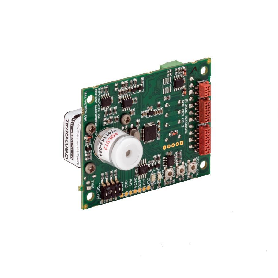
3 1. Description The Aeroqual SM50 range of gas sensor modules provides state of the art gas measurement in a flexible cost effective package. They utilise Aeroqual s GSS Technology to provide reliable and sensitive measurement for a wide range of gases. There are two gas response specifications available - Standard for industrial process control or leak detection applications and High Spec for low level ambient gas measurements. Furthermore the modules are available in diffusion, fan and pump sampling versions. Please consult your Aeroqual Business Development Manager for further information. Each SM50 module is calibrated to give a linear output with gas concentration. There are multiple outputs fitted as standard including diagnostic LEDS, 0-5V signal, relay, RS232, and RS485 digital communications. I2C is available as an option. Standard inputs include dipswitch settings for the relay and calibration buttons. Optional inputs include two analog voltages. MICROMATCH CONNECTORS (SCREW TERMINALS AVAILABLE ON UNDERSIDE) ZERO CAL BUTTON RESET BUTTON SPAN CAL BUTTON* RELAY LED STATUS LED OPTIONAL INPUTS GSS SENSOR RELAY SET POINT DIP SWITCHES * This button will change the span calibration of the SM70 and should not be activated for any reason 2. Operating Instructions 2.1. Power The SM50 module will run off a DC input voltage in the range VDC. Connect power to the V+ and GND screw terminal connectors or to the VIN and GND pins on the micromatch connectors. Power consumption varies depending on the SM50 sensor in the range 2.5 to 6W Warm Up The SM50 module is designed to run continuously. On first time use or after a period of non-use the SM50 module should be run for a couple of hours to burn off contaminants on the sensor. When power is switched on the SM50 will warm up for 3-10 minutes before full operation Input and Output signals The SM70 sensor board contains a number of buttons, LEDs and a dipswitch. Page 3
4 ZERO CAL This button activates a zero calibration routine on the sensor. It should only be pushed when you are performing a zero calibration RESET This button resets the SM50 without needing to remove the power from the SM SPAN This button will change the span calibration of the SM70 and should not be activated for any reason Using the Relay Output The SM50 sensor module can be used as a simple gas sensitive relay switch to control devices or activate alarms using the on board relay. Three relay control software options are available: AA, AB, C10. The user should specify the software prior to delivery. The relay logic of the three software versions is described below. External equipment connected to the on-board relay should be wired appropriately to the normally open or normally closed contacts AA Alarm-Above: the relay is programmed to energise or activate above the selected set point. Typical applications are health and safety alarm/warning systems or switching external equipment on and off. This is the default software. Relay closed (energised) Set Point Relay open (de-energised) When gas concentration is rising from below the Set Point, relay de-energised (relay NO=open, NC=closed) When gas concentration rises and reaches the Set Point, relay is energised (relay NO= closed, NC = open) When gas concentration drops and reaches the Set Point, relay de-energised (relay NO=open, NC=closed) AB Alarm-Below: the relay is programmed to energise or activate below the selected set point. Typical applications are fail safe warning systems or controlling a gas generator. Relay open (de-energised) Set Point Relay closed (energised) Page 4
5 C10 When gas concentration is rising from below the Set Point, relay energised (relay NO= closed, NC = open) When gas concentration rises and reaches the Set Point, relay is de-energised (relay NO= open, NC = closed) When gas concentration drops and reaches the Set Point, relay energised (relay NO=closed, NC=open) The relay is programmed to open and close around the selected control set point ±10% to create a control band. Typical application is for maintaining a specific gas concentration between user defined levels through the control of an external device e.g. ozone generator. Upper Limit 110% 100% Relay closed (energised) Relay open (de-energised) Set Point Software Control Band ±10% of set point 90% Lower Limit When the gas level is rising from below Lower Limit to Upper Limit, relay is energised, (NO=closed, NC = open) When gas level is falling from above Upper Limit to Lower Limit, relay is de-energised (NO=open, NC = closed) Setting the Relay and Alarm Set Point The Relay Set Point can be altered by adjusting the set-point dip-switches as shown below. The Relay Set Point is factory set (unless otherwise specified) to OFF-ON-OFF-ON. The set point levels for different dipswitch settings are provided below for some sensors. Contact Aeroqual if your sensor is not listed. Note: The relay and sensor diagnostics are inactive during the warm up period. Relay dipswitch ( ) O (ppm) O (ppm) O (ppm) VOC Isobutylene (ppm) on on on on off on on on on off on on off off on on on on off on off on off on * on off off on off off off on on on on off off on on off on off on off off off on off on on off off off on off off on off off off off off off off * Factory default setting Page 5
 or for a higher voltage and current loads via a secondary relay. A typical external device is an alarm bell, siren, extractor fan, etc.")
6 Connecting to the Relay Outputs The relay output is a set of volt-free contacts that can be used to trigger an external device directly (max. 2A) or for a higher voltage and current loads via a secondary relay. A typical external device is an alarm bell, siren, extractor fan, etc. When the relay is energised (the red relay LED will light up) the normally open (NO) will short to common (COM) and the normally closed (NC) will be open with respect to COM. Connect the desired external device to the normally open (NO), normally closed (NC) and COM contacts on the screw terminal as shown below. EXTERNAL DEVICE e.g. O3 generator Insert jumper wire between Com and GND Com NO GND V+ Insert diode in circuit to suppress back EMF Diode IN4004 External relay must be suitably rated to switch the external load Operating voltage of relay coil must be 12 VDC L N E 240 VAC 2.5. Status LED (Normal and Failure modes) The status LED glows green and is located on the Sensor board. At start up, the Status LED will flash 2 to 6 times at an interval of 0.5 seconds. During the 3 to 10 minute warm-up time, the Status LED will flash at an interval of 2 seconds. Normal status: Constant on Sensor Failure: Flashes quickly at an interval of 0.3 seconds Relay LED The relay LED glows red and is also located on the Sensor board. This LED comes on when the relay is energised. Page 6
. The resolution of the analog signal is 8 bit. Note: The 0-0.")
7 2.6. Using the Analog 0-5V Output The gas concentration is available as a 0-5V signal at the 0-5V and AGND connectors on the screw terminal block. 0 volts = zero ppm and 5 V = designated range of sensor (for example, a ppm O3 SM70 module would output 5V at ppm ozone). The resolution of the analog signal is 8 bit. Note: The ppm O3 sensor analogue output is 1.5V at 0.150ppm (full scale). All other sensors output 5.0V at full scale Using the Serial Digital Communications Gas concentration data is available on the RS232 and RS485 digital communication channels. The RS485 channel is 2-wire, the RS232 is 2-wire plus GND. Connection is via the screw terminal connectors on the sensor board. The communication protocols for these serial interfaces are provided in the Appendix. Please note: the RS232 serial protocol is a proprietary format and is not ASCII. Hence a terminal program cannot be used to communicate with the SM50. Program Connector Communication Connector Display Connector Program Connector PIN CONFIG. VCC (5V) BUSY Communication Connector CLK R x D RS485 GND RESET CNV T x D RS485 N/A VIN (11-24V) PIN CONFIG. VIN GND METER_TX METER_RX (11-24V) (RS232) (RS232) Display Connector PIN CONFIG. GND VCC (5V) SCL (clock) SDA (data) SPAN ZERO 0-5V OUT (analog) AGND (analog GND) Page 7
8 3. Specifications Power Input Consumption VDC W max Outputs 0-5V analog 8 bit Relay Onboard 24VDC / 2A, NO, NC, COM 2 x LED indicators Relay status Red = activated Sensor status Green = normal Green slow flash (2 seconds) = warming up Green fast flash (0.3 seconds) = failure RS232 2-wire proprietary protocol (not ASCII) RS485 2-wire proprietary protocol (not networkable) Inputs Relay set points Zero calibration Reset Span calibration Analog inputs 4-way dip switch Auto-calibration zero button Microprocessor reset button Factory use only 2 Voltage (optional) Diagnostics If sensor failure then:- Status LED fast green flash Relay AA version (energised) LED red AB version (de-energised) LED off C10 version (de-energised) LED off 0-5V analog output 5V Mechanical Board Size Mounting Fan (if required) Sensor filter 60 mm x 75 mm Screw or extrusion slot On-board ball-bearing 50,000 hours On-board Environmental Operating temperature Operating humidity 0ºC to 50ºC (-20ºC to 50ºC if enclosed) 5% to 95% RH (non-condensating) Approvals Page 8


9 14mm 4mm 67mm 4mm 75mm 4. Mounting Dimensions The mounting points and dimensions are given below for an SM50 ozone sensor. Individual SM50 modules may differ slightly to that shown. HOLES 4mm Ø 15mm 15mm TEFLON TUBE 16mm Ø ID 19mm Ø OD 30mm long 30mm 30mm 10-14mm 16-20mm TEFLON TUBE 16mm (min) 20mm (max) protrusion outside the enclosure 5.5mm 49mm 60mm 5.5mm 1.5mm Page 9
10 5. Appendix 5.1. RS232 Protocol The Aeroqual OEM sensor s digital information output is based on the following RS232 protocol. These command protocols are specified by Aeroqual Limited, all rights reserved. Aeroqual reserves the right to change the protocol without notification. Version 2.2 Date: * Added zero calibration function. * Combined with temperature and relative humidity sensor data. Section 1. Descriptions of communication commands (for data format and representations please refer to section 3). Comma and spaces are not applied for every command and reply data stream, they are just used for clearly specifying data stream: 1. OEM sensor regular data report command; the data report interval varies with sensor. It is 15 bytes data stream: SENSOR, DATA_REPORT, DATA1, DATA2, DATA3, RESERVED2, STATUS1, STATUS2, CHECKSUM * SENSOR - 1 byte monitor reply data stream header, see section 2 for its value. * DATA_REPORT - 1 byte data report command, see section 2 for its value. * DATA1-4 bytes floating point data, gas concentration value. * DATA2-2 bytes unsigned int used for optional sensors of temperature reading, its value scaled up by 10. that means if the reported value is 256, then the actual reading is 25.6 Celsius degree. * DATA3-2 bytes unsigned int used for optional sensors of relative humidity reading, its value scaled up by 10. that means if the reported value is 515, then the actual reading is 51.5%. * RESERVED2 - is 2 bytes reserved. * STATUS1-1 byte sensor status indication, refer section 3 for details. * STATUS2-1 byte sensor status indication, refer section 3 for details. * CHECKSUM - 1 byte the data stream's check sum - that makes the command stream total sum is zero. 2. OEM sensor information request command: Command RECEIVER, SENSOR_INFO, RESERVED1, CHECKSUM Reply SENSOR, SENSOR_INFO, VERSION_NO, DISPLAY, NMAE_LENGTH, SENSOR_NAME, RESERVED2, CHECKSUM * RECEIVER - 1 byte information request command header, see section 2 for its value. * SENSOR - 1 byte monitor reply data stream header, see section 2 for its value. * SENSOR_INFO - 1 byte command see section 2 for its value * VERSION_NO - 1 byte sensor version number, see section 2 for its value. * DISPLAY - 1 byte, gas concentration value display format type, see section 2 for its value. * NAME_LENGTH - 1 byte specify the sensor name byte length * SENSOR_NAME - 7 bytes, the gas sensor name ASCII code, its valid bytes are specified by NMAE_LENGTH * RESERVED1-1 bytes reserved use value 0x00. * RESERVED2-2 bytes not used. Page 10
11 * CHECKSUM - 1 byte the data stream's check sum - that makes the command stream total sum is zero. 3. OEM sensor concentration ppm to mg/m3 conversion factor request command: Command Reply RECEIVER, CONVERT_FACTOR, RESERVED1, CHECKSUM SENSOR, CONVERT_FACTOR, FACTOR, RESERVED8, CHECKSUM * SENSOR - 1 byte monitor reply data stream header, see section 2 for its value. * CONVERT_FACTOR - 1 byte command see section 2 for its value * FACTOR - 4 bytes floating point conversion factor value, see section 3 for details. * RESERVED1-1 bytes reserved use value 0x00. * RESERVED8-8 bytes reserved. * CHECKSUM - 1 byte the data stream's check sum - that makes the command stream total sum is zero. 4. OEM sensor zero calibration command, 4 bytes: Command RECEIVER, ZERO_CAL, RESERVED1, CHECKSUM * ZERO_CAL - 1 byte (0x12) command to start zero calibration for the sensor, see section 2 for its value. * RESERVED1-1 bytes reserved use 0x00. * CHECKSUM - 1 byte the data stream's check sum - that makes the command stream total sum is zero. * During zero calibration OEM status LED will slowly flash, once the flash finished, zero calibration * finished too. Section 2. Protocol command values: RECEIVER = 0x55 //header command used for receiver command SENSOR = 0xAA //header command used for monitor reply DATA_REPORT = 0x10 //regular data report command ZERO_CAL = 0x12 //zero calibration command SENSOR_INFO = 0xFB //parameters upload command CONVERT_FACTOR = 0x2A //update monitor real time clock RESERVED = 0x00 //the byte not been used for information transfer CHECKSUM a data stream's check sum - that makes the command stream total sum is zero. DISPLAY display format can be following: = 0x01-1 digit int, 3 decimal points, eg ppm = 0x02-2 digits int, 2 decimal points, eg ppm = 0x03-3 digits int, 1 decimal point, eg ppm = 0x04-4 digits int, no decimal point, eg ppm STATUS1 8 bits monitor and sensor status information SS0 * b0 \ 00 sensor working fine, SS1 * b1 / 01 sensor failure, 11 sensor aging (for O3 LOW sensor only). Reserved1 Reserved2 Reserved3 Reserved4 * b2 Reserved not been used * b3 Reserved not been used * b4 Reserved not been used * b5 Reserved not been used Page 11
12 Reserved5 Reserved6 * b6 Reserved not been used * b7 Reserved not been used STATUS2 8 bits monitor and sensor status information Reserved0 * b0 Reserved not been used Reserved1 * b1 Reserved not been used Zeroing * b2 = 0 sensor normal working mode * b2 = 1 sensor zeroing Reserved2 * b3 Reserved not been used Reserved3 * b4 Reserved not been used Reserved4 * b5 Reserved not been used Reserved5 * b6 Reserved not been used Reserved6 * b7 Reserved not been used Section 3. Data value format representation: The floating point data values use IEEE bits floating point little ending representation. They are: DATA1 and FACTOR Section 4. Data transfer mechanism 1. Due to the monitor main chips feature, 4 bytes floating point data and 2 bytes int data send sequence are low byte first, high byte last, such as section 3 data DATA1, DATA2, ADAT3 and FACTOR. 2. For regular data report: The OEM sensor will automatically send out a measured data result to the RS232 serial port according to sensor type. The data report interval will vary with different sensors. The longest report interval is about 2 minutes, the shortest one is only 2 seconds. Please ask Aeroqual for this information when needed. Section 5. RS232 communication port settings: Baud rate: 9600 Data bits: 8 Stop bits: 1 Parity: none Flow control: none Page 12
13 5.2. RS485 Protocol The Aeroqual OEM sensors digital information output is available on RS485. These command protocols are specified by Aeroqual Limited, all rights reserved. Aeroqual keep the rights to change the protocol without notification. Version 1.0 Date: Section 1. Descriptions of communication commands (for data format and representations please refer to section 3). Comma and spaces are not applied for every command and reply data stream, they are just used for clearly specifying data stream: Aeroqual OEM sensor module RS485 protocol is a slave mode. Master receivers need send request command to get response. 1. OEM sensor data request command, it is 4 bytes data stream: BASE, DATA_REQUEST, RESERVED, CHECKSUM example: 0x55, 0x1A, 0x00, 0x91 Reply data stream is 15 byte. SENSOR, DATA_REPORT, DATA1, DATA2, RESERVED, STATUS1, STATUS2, CHECKSUM The second byte (DATA REPORT) will be either 0x1A or 0x0F or 0x10. Only if DATA REPORT = 0x10 will DATA1 be a valid concentration reading. * SENSOR - 1 byte monitor reply data stream header, see section 2 for its value. * DATA_REQUEST - 1 byte heater data report, see section 2 for its value. * DATA_REPORT - 1 byte gas concentration data report command, see section 2 for its value. * DATA1-4 bytes floating point data, when command reply is DATA_REPORT, this value is gas concentration in ppm, * DATA2 - reserved * RESERVED - is 2 bytes data space reserved. * STATUS1-1 byte monitor and sensor status indication, refer section 3 for details. * STATUS2-1 byte reserved. * CHECKSUM - 1 byte the data stream's check sum - that makes the command stream total sum is zero. 2. OEM sensor information request command: Command BASE, SENSOR_INFO, RESERVED, CHECKSUM Reply SENSOR, SENSOR_INFO, VERSION_NO, DISPLAY, NMAE_LENGTH, SENSOR_NAME, RESERVED, CHECKSUM * BASE - 1 byte information request command header, see section 2 for its value. * SENSOR - 1 byte monitor reply data stream header, see section 2 for its value. * SENSOR_INFO - 1 byte command see section 2 for its value * VERSION_NO - 1 byte sensor version number, see section 2 for its value. * DISPLAY - 1 byte, gas concentration value display format type, see section 2 for its value. * NAME_LENGTH - 1 byte specify the sensor name byte length Page 13
14 * SENSOR_NAME - 7 bytes, the gas sensor name ASCII code, its valid bytes are specified by NMAE_LENGTH * RESERVED - 1 byte * CHECKSUM - 1 byte the data stream's check sum - that makes the command stream total sum is zero. Section 2. Protocol command values are in hexdecimals not ASCII: BASE = 0x55 //header command used for receiver command SENSOR = 0xAA //header command used for monitor reply DATA_REPORT = 0x10 //regular data report command DATA_REQUEST = 0x1A //heater data request/report command SENSOR_INFO = 0xFB //parameters upload command RESERVED = 0x00 //the byte not been used for information transfer CHECKSUM * a data stream's check sum - that makes the command stream total sum is zero. DISPLAY * display format can be following: = 0x01-1 digit int, 3 decimal points, eg ppm = 0x02-2 digits int, 2 decimal points, eg ppm = 0x03-3 digits int, 1 decimal point, eg ppm = 0x04-4 digits int, no decimal point, eg ppm STATUS1 * 8 bits monitor and sensor status information SS0 * b0 \ 00 sensor working fine, SS1 * b1 / 01 sensor failure, 11 sensor aging. Reserved1 Reserved2 Reserved3 Reserved4 Reserved5 Reserved6 * b2 Reserved not been used * b3 eserved not been used * b4 Reserved not been used * b5 Reserved not been used * b6 Reserved not been used * b7 Reserved not been used Section 3. Data value format representation: The floating point data values use IEEE bits floating point little ending representation. They are: DATA1, DATA2 Section 4. Data transfer mechanism Due to the monitor main chips feature, 4 bytes floating point data and 2 bytes int data send sequence are low byte first, high byte last, such as section 3 data DATA1 and FACTOR. Section 5. RS485 communication port settings: Baud rate: 4800 Data bits: 8 Stop bits: 1 Parity: none Flow control: none Page 14
Page 1 MRK-D-0011, V2.0 Aeroqual SM50 User Guide
 Page 1 Table of Contents User Guide Revision History... 3 Description... 4 1. Operating Instructions... 4 1.1. Power... 4 1.2. Warm Up... 4 1.3. Standard Inputs and Outputs... 4 1.4. Using the Relay Output...
Contents. MRK-D-0017, V2 Aeroqual SM70 User Guide Page 2
 Contents 1. For Your Safety... 3 2. SM70 Components... 3 3. About Your Monitor / Controller... 3 4. Getting Started... 4 4.1. Installation... 4 4.2. Turning the monitor on and off... 4 4.3. Warming up...
Page 1 MRK-D-0017, V1 Aeroqual SM70 User Guide
 Page 1 Contents Contents... 2 For Your Safety... 3 1. SM70 Components... 3 2. About Your Monitor / Controller... 3 3. Getting Started... 4 3.1. Installation... 4 3.2. Turning the monitor on and off...
Eco Sensors OZONE CONTROLLER Model OS-6 Instructions for Use. General and New Features
 Eco Sensors OZONE CONTROLLER Model OS-6 Instructions for Use General and New Features The OS-6 is an industrial grade Ozone controller and monitor. The OS-6 design has been optimized for accuracy, ease
ES-600 Ozone Controller Operation Manual
 ES-600 Ozone Controller Operation Manual Questions about your product? Find answers here: Web: www.ozonesolutions.com/es-600 Phone: 712-439-6880 Ozone Solutions OZONE CONTROLLER Model ES-600 Instructions
OZONE SWITCH Model OS-6. OS-6 Features
 USER MANUAL OZONE SWITCH Model OS-6 OS-6 Features The OS-6 is an industrial grade ozone controller and monitor. The OS-6 design is optimized for accuracy and ease of installation, setup and operation.
Eco Sensors OZONE CONTROLLER Model OS-6 Instructions for Use. General and New Features
 Eco Sensors OZONE CONTROLLER Model OS-6 Instructions for Use General and New Features The OS-6 is an industrial grade Ozone controller and monitor. The OS-6 design has been optimized for accuracy, ease
HPS-M -2 DIFFERENTIAL PRESSURE TRANSMITTER. Mounting and operating instructions
 DIFFERENTIAL PRESSURE Mounting and operating instructions Table of contents SAFETY AND PRECAUTIONS 3 PRODUCT DESCRIPTION 4 ARTICLE CODES 4 INTENDED AREA OF USE 4 TECHNICAL DATA 4 STANDARDS 5 OPERATIONAL
RXTH DUAL ROOM SENSOR / SWITCH
 DUAL ROOM SENSOR / SWITCH FOR TEMPERATURE AND RELATIVE HUMIDITY Mounting and operating instructions Table of contents SAFETY AND PRECAUTIONS 3 PRODUCT DESCRIPTION 4 ARTICLE CODES 4 INTENDED AREA OF USE
DSTHM-2 COMBINED T AND RH DUCT TRANSMITTER. Mounting and operating instructions
 Mounting and operating instructions Table of contents SAFETY AND PRECAUTIONS 3 PRODUCT DESCRIPTION 4 ARTICLE CODES 4 INTENDED AREA OF USE 4 TECHNICAL DATA 4 STANDARDS 4 OPERATIONAL DIAGRAMS 5 WIRING AND
DXTH DUCT SENSOR / SWITCH FOR TEMPERATURE AND HUMIDITY. Mounting and operating instructions
 DUAL DUCT SENSOR / SWITCH FOR TEMPERATURE AND HUMIDITY Mounting and operating instructions Table of contents SAFETY AND PRECAUTIONS 3 PRODUCT DESCRIPTION 4 ARTICLE CODES 4 INTENDED AREA OF USE 4 TECHNICAL
Rev Carbon Dioxide (CO2) Gas Sensor. TG100 User Manual
 Gas Sensor. TG100 User Manual") Rev. 2.5 TG100 User Manual The TG100 measuring carbon dioxide (chemical formula CO2) is a NDIR (Non-Dispersive Infrared) gas sensor. As it is contactless, it has high accuracy and longer life than sensors
Rev. 2.5 TG100 User Manual The TG100 measuring carbon dioxide (chemical formula CO2) is a NDIR (Non-Dispersive Infrared) gas sensor. As it is contactless, it has high accuracy and longer life than sensors
RST ROOM TEMPERATURE TRANSMITTER. Mounting and operating instructions
 Mounting and operating instructions Table of contents SAFETY AND PRECAUTIONS 3 PRODUCT DESCRIPTION 4 ARTICLE CODES 4 INTENDED AREA OF USE 4 TECHNICAL DATA 4 STANDARDS 4 OPERATIONAL DIAGRAM 5 WIRING AND
ZBXYAF Oxygen sensor control circuit board
 FEATURES Control circuit board for all XYA series oxygen sensors Measuring ranges...5 or... oxygen or custom adjustable range Can be calibrated in normal air or any known O concentration Automatic or manual
RXTP ROOM TEMPERATURE
 ROOM TEMPERATURE CONTROLLER WITH PI CONTROL Mounting and operating instructions Table of contents SAFETY AND PRECAUTIONS 3 PRODUCT DESCRIPTION 4 ARTICLE CODES 4 INTENDED AREA OF USE 4 TECHNICAL DATA 4
Rev Carbon Dioxide (CO2) Gas Sensor. TG100 User Manual
 Gas Sensor. TG100 User Manual") Rev. 2.93 TG100 User Manual The TG100 measuring carbon dioxide (chemical formula CO2) is a NDIR (Non-Dispersive Infrared) gas sensor. As it is contactless, it has high accuracy and longer life than sensors
Rev. 2.93 TG100 User Manual The TG100 measuring carbon dioxide (chemical formula CO2) is a NDIR (Non-Dispersive Infrared) gas sensor. As it is contactless, it has high accuracy and longer life than sensors
MOD-RI Room Interface Modules with Modbus
 Product sheet MOD3.00 Type MOD-RI MOD-RI Room Interface Modules with Modbus The MOD-RI are room interface modules designed to provide room control interface for the building management systems. The MOD-RI
Model 305e OEM CO 2 concentration sensor
 Model 305e OEM CO 2 concentration sensor preliminary Reference manual DIGITAL CONTROL SYSTEMS 7401 SW Capitol Hwy. Portland, OR 97219 USA 503/246-8110 503/246-6747 (fax) www.dcs-inc.net Scope...3 Introduction...3
Carbon Monoxide Sensor - ModBus
 Introduction The CO Sensor uses an electrochemical sensor to monitor CO level in a range of 0 to 500 ppm and communicates via an RS-485 network configured for ModBus protocol. Before Installation Read
OEM Digital NDIR CO 2
 OEM Digital NDIR CO 2 sensor with flow-through gas cell Model 2015SPI-3 The VALTRONICS Model 2015SPI-3 is an OEM NDIR CO 2 sensor with digital signal processing and temperature compensation. The firmware
OEM Digital NDIR CO sensor
 OEM Digital NDIR CO sensor with flow-through gas cell Model 2015SPI-CO-20 The VALTRONICS Model 2015SPI-CO-20 is an OEM NDIR CO sensor with digital signal processing and temperature compensation. The firmware
RTT2 ROOM TEMPERATURE SWITCH. Mounting and operating instructions
 Mounting and operating instructions Table of contents SAFETY AND PRECAUTIONS PRODUCT DESCRIPTION ARTICLE CODES INTENDED AREA OF USE TECHNICAL DATA STANDARDS OPERATIONAL DIAGRAMS WIRING AND CONNECTIONS
TOXALERT MODEL AIR 2000
 TOXALERT MODEL AIR 2000 NOTE: Toxalert s Model GVU-CO 2 Sensor is the same as the Air2000R. Microprocessor-based, Infrared Environmental CO 2 Sensor OPERATOR S MANUAL TOXALERT TM INTERNATIONAL INC. P.O.
Intech Micro 2300-A8VI analogue input station MODBUS RTU slave application supplementary manual.
 Intech Micro 2300-A8VI analogue input station MODBUS RTU slave application supplementary manual. MODBUS supplementary manual to the 2300-A8VI Installation Guide. The 2300 series stations are designed to
KCD-HP. KCD-HP200x, 300X. [Figures] Top : 1% Sensor probe Bottom left : 10% / 20% Sensor probe Bottom right : Holding bracket(optional) Measurement
![KCD-HP. KCD-HP200x, 300X. [Figures] Top : 1% Sensor probe Bottom left : 10% / 20% Sensor probe Bottom right : Holding bracket(optional) Measurement](/thumbs/80/81495049.jpg "KCD-HP. KCD-HP200x, 300X. [Figures] Top : 1% Sensor probe Bottom left : 10% / 20% Sensor probe Bottom right : Holding bracket(optional) Measurement") Our CO2 gas sensors get a small deviation unlike NDIR Single type. So they keep long term stability. KCD-HP100x Excellent stability and accuracy - through testing and calibration with sophisticated process
Our CO2 gas sensors get a small deviation unlike NDIR Single type. So they keep long term stability. KCD-HP100x Excellent stability and accuracy - through testing and calibration with sophisticated process
RТTH DUAL ROOM SWITCH
 DUAL ROOM SWITCH FOR TEMPERATURE AND RELATIVE HUMIDITY Mounting and operating instructions Table of contents SAFETY AND PRECAUTIONS PRODUCT DESCRIPTION ARTICLE CODES INTENDED AREA OF USE TECHNICAL DATA
2.2 Main technical parameters. Detection range. 0~5%vol(0~100%vol optional) Warm-up time. SPAN <±500ppm Long-term drift
 Warm-up time. SPAN <±500ppm Long-term drift") MH-440D infrared gas sensor 1. Introduction MH-440D infrared gas sensor is a miniature universal intelligent sensor, which adopts NDIR theory to detect concentration of CH4 in air and has good selectivity,
MH-440D infrared gas sensor 1. Introduction MH-440D infrared gas sensor is a miniature universal intelligent sensor, which adopts NDIR theory to detect concentration of CH4 in air and has good selectivity,
General. Copyright 2013 EXSEN Company. All Rights Reserved. Rev /5/2013 Page 1 of 6
 General World smallest and economic solid state electrochemical CO 2 sensor has been developed for the production. It holds many patents in the structure and the materials of the sensor as well as the
Manual iaq-engine Indoor Air Quality sensor
 Manual iaq-engine, Version 2.0 May 2011 (all data subject to change without notice) Manual iaq-engine Indoor Air Quality sensor Digital and analog I/O SMD type package Product summary iaq-engine is used
TEMPERATURE CONTROLLER 2 HEAT/ 2 COOL with Digital Room Temperature Display. Made in Australia 100% Australian Owned Company
 TEMPERATURE CONTROLLER 2 HEAT/ 2 COOL with Digital Room Temperature Display HTC 5 Features Australian Made and designed Power can be either 24V or 240V AC 10 Amp (Resistive) Potential free relay contacts
Series 900 & 905 Transmitter/ Controller. User Guide
 Series 900 & 905 Transmitter/ Controller User Guide 1 Table of Contents 1. Description 2 1.1 Components supplied 2 1.2 Components not supplied but required 2 2. Configuration 3 2.1 Using a USB to RS485
Contents. MRK-D-0009, V3 Page 2 Aeroqual Series 940 User Guide
 Contents 1. Description... 3 1.1. Series 940 Components... 3 1.1.1 Components supplied... 3 1.1.2 Components not supplied but required... 3 1.1.3 Components (optional)... 4 2. Configuration... 5 2.1. Using
The PM1000 series is a universal 4 digit LED plug-on display for transmitters with 4-20mA 2 wire output and fitted with DIN43650 connector.
 PM1000 SERIES PLUG-ON DISPLAY BRIGHT LED DISPLAY INDICATION RANGE -999 TO +9999 FITS TO DIN 43650 CONNECTOR PLUG-ON TO ANY TRANSMITTER WITH 4-20MA OUTPUT EASY TO SCALE ON SITE ROBUST DESIGN SET POINT OPTION
Aeroqual Series 900 User Guide
 Page 1 Contents 1. Description... 3 1.1. S900 Components... 3 1.2. Components not supplied but required... 3 2. Configuration... 3 2.1. Using the Aeroqual USB to RS485 converter... 3 2.2. Configuring the
S125 Multi-Purpose 125 KHz RFID Reader USER MANUAL. 9V/24V DC Operating Voltage, AC (optional) KHz RFID EM4100/2 Cards & Tags
 KHz RFID EM4100/2 Cards & Tags") S125 Multi-Purpose 125 KHz RFID Reader 44 mm USER MANUAL MULTI PURPOSE 84 mm ONLINE & OFFLINE MODE BUILT-IN RELAY 125 KHz RFID EM4100/2 Cards & Tags 9V/24V DC Operating Voltage, AC (optional) 3 Online
S125 Multi-Purpose 125 KHz RFID Reader 44 mm USER MANUAL MULTI PURPOSE 84 mm ONLINE & OFFLINE MODE BUILT-IN RELAY 125 KHz RFID EM4100/2 Cards & Tags 9V/24V DC Operating Voltage, AC (optional) 3 Online
Rev 1.3, Air-Farm User Manual. CO2 / Temperature / Humidity Transmitter
 Rev 1.3, 2018-06 Air-Farm User Manual CO2 / Temperature / Humidity Transmitter Features CO2, Temperature and Humidity measurement Three high sensitivity sensors RS485(MODBUS) Communication Analog Voltage
Suprex Fiber Optic. Reader-Extender SPX-7400 SPX Product Manual. Reader-Extender. Manual. SPX-7400 Series EXP Suprex_FiberOptic_MAN_170502
 Suprex Fiber Optic Reader-Extender SPX-7400 SPX-7410 Product Manual Reader-Extender Manual SPX-7400 Series EXP-2000 Suprex_FiberOptic_MAN_170502 Cypress Integration Solutions 30+ Years of Access Control
Product Specification. tsense VAV. CO 2 -, Temperature- and RH- sensor in a housing with colour touch display
 Product Specification tsense VAV CO 2 -, Temperature- and RH- sensor in a housing with colour touch display General tsense VAV is an advanced and versatile 3-in-1 transmitter designed for installation
LD-RTD / LD-TC Temperature Controller
 1 LD-RTD / LD-TC Temperature Controller Available in either an RTD model or a thermocouple model, these units accept all common temperature probe types, and offer a technically advanced, but cost effective
RTD-W Installation Instructions
 RTD-W Installation Instructions 0V +V POWER 15-24VDC 0V S1 S2 S3 0V S4 S5 S6 English RTD-W Installation Instructions 100.00 RTD-W Control Interface realtime Control Systems 24VAC/30VDC, 1A REMC P1 P2 RS485
SCDM88-8x8 Serial LED Dot Matrix Display Module. Serial Interface. Serial Command Summary
 SCDM88-8x8 Serial LED Dot Matrix Display Module 8x8 Red LED Dot Matrix RS232 Interface Simple Serial Command Built in ASCII characters font 4 Built in Animation 60mm x 60mm 10 user s define characters/bitmap
Intelligent Infrared CO 2 Gas Sensor. (Model: MH-711A) Manual. Version: 3.3. Valid from: May 1st, 2014
 Manual. Version: 3.3. Valid from: May 1st, 2014") Intelligent Infrared CO 2 Gas Sensor (Model: MH-711A) Manual Version: 3.3 Valid from: May 1st, 2014 Zhengzhou Winsen Electronics Technology Co., Ltd. Statement This manual copyright belongs to Zhengzhou
Intelligent Infrared CO 2 Gas Sensor (Model: MH-711A) Manual Version: 3.3 Valid from: May 1st, 2014 Zhengzhou Winsen Electronics Technology Co., Ltd. Statement This manual copyright belongs to Zhengzhou
PCD DIGITAL Differential pressure probe
 Differential pressure probe 2016 ROTRONIC AG Bassersdorf Switzerland Contents 1 Overview... 3 1.1 Hardware and software compatibility... 3 2 Variants... 4 3 General information... 6 3.1 Power supply...
Intech Micro 2300-RO4 analogue input station MODBUS RTU slave application supplementary manual.
 Intech Micro 2300-RO4 analogue input station MODBUS RTU slave application supplementary manual. MODBUS supplementary manual to the 2300-RO4 Installation Guide. The 2300 series stations are designed to
SmartFan Fusion-4. Speed Control and Alarm for DC Fans CONTROL RESOURCES INCORPORATED. The driving force of motor control & electronics cooling.
 SmartFan Fusion-4 Speed Control and Alarm for DC Fans The driving force of motor control & electronics cooling. P/N FUS300-F DC Controls SmartFan Fusion-4 is a digital fan speed control and alarm that
TPE 1464 Series Pressure Transducer
 TPE 1464 Series Pressure Transducer Description The KMC TPE 1464 series of pressure transducers incorporate a gauge pressure transmitter featuring low hysteresis, excellent repeatability, and longterm
Suprex RS-485 SPX-7500 Wired Reader-Extender
 Suprex RS-485 SPX-7500 Wired Reader-Extender Product Manual SPX-7500_MAN_181206 Cypress Integration Solutions 35 Years of Access Control Ingenuity CypressIntegration.com 2018 Cypress Computer Systems 1778
USER INSTRUCTION MANUAL FOR LOADCELL TRANSMITTER MODEL TDC/I/0550 (SOFTWARE: VER2A) INDEX
 INDEX") USER INSTRUCTION MANUAL FOR LOADCELL TRANSMITTER MODEL TDC/I/0550 (SOFTWARE: VER2A) INDEX DOCUMENT NO: TDC 0550 MANUAL - 2 1.0) INTRODUCTION. PAGE 2 1.1) ABOUT THIS MANUAL. PAGE 2 1.2) INTRODUCTION. PAGE
USER INSTRUCTION MANUAL FOR LOADCELL TRANSMITTER MODEL TDC/I/0550 (SOFTWARE: VER2A) INDEX DOCUMENT NO: TDC 0550 MANUAL - 2 1.0) INTRODUCTION. PAGE 2 1.1) ABOUT THIS MANUAL. PAGE 2 1.2) INTRODUCTION. PAGE
NSGV Series "90DM3" Carbon Dioxide Detector
 NSGV SERIES 90DM3 CARBON DIOXIDE DETECTOR NSGV Series "90DM3" Carbon Dioxide Detector 90DM3A Specifications. Power 17-27 VAC, 24-38 VDC, 200 ma Detection Range 0-200 PPM Relay Output Rating 5A, 30 Vdc
Please Read Instruction Carefully Before Installation! Figure 1: A/CO2-DUCT
 Installation and Operation Instructions A/CO2-DUCT Series Please Read Instruction Carefully Before Installation! Figure 1: A/CO2-DUCT PRECAUTIONS REMOVE POWER BEFORE WIRING. NEVER CONNECT OR DISCONNECT
SPX-7400_SPX-7410_MAN_161028
 Suprex Fiber Optic SPX-7400 & SPX-7410 Suprex Reader-Extender Data Sheet SPX-7400 Series EXP-2000 SPX-7400_SPX-7410_MAN_161028 1 Cypress Suprex SPX-7400 & SPX-7410 Overview The Suprex Fiber Optic SPX-7400
Suprex RF Series CYPRESS. Operations Manual. Suprex Reader Extender - RF Wireless Interface EXP SPX Mhz SPX-5521_MAN_0316
 CYPRESS Suprex RF Series Operations Manual Suprex Reader Extender - RF Wireless Interface EXP-2000 SPX-5521 900 Mhz SPX-5521_MAN_0316 Cypress Suprex SPX-5521 Series Overview This manual covers the operation
EE360. High-End Moisture in Oil Transmitter. Typical applications. Features EE360 EE360. (+34)
") is dedicated for reliable monitoring of lubrication, hydraulic and insulation oils as well as diesel fuel. In addition to highly accurate measurement of water activity (a w ) and temperature (T), calculates
is dedicated for reliable monitoring of lubrication, hydraulic and insulation oils as well as diesel fuel. In addition to highly accurate measurement of water activity (a w ) and temperature (T), calculates
Manual and Protocol Description
 Communication Module MSR240 1 Manual and Protocol Description Overview The MSR240 Communication Module serves as an interface between a MSR210 or MSR211 Basic Module and a standard serial data communication
CDD Carbon Dioxide Transmitter
 Introduction The OSA CO2 transmitter uses Infrared Technology to monitor CO2 levels within a range of 0 2000 ppm and outputs a linear 4-20 ma or 0-5/0-10 Vdc signal. The enclosure is designed to operate
CDN503 HIGH DENSITY I/O ADAPTER USER GUIDE
 CDN503 HIGH DENSITY I/O ADAPTER USER GUIDE 13050301 (c) Copyright DIP Inc., 1996 DIP Inc. P.O. Box 9550 MORENO VALLEY, CA 92303 714-924-1730 CONTENTS DN503 PRODUCT OVERVIEW 1 DN503 INSTALLATION 1 POWER
HART USER GUIDE FOR GASSONIC OBSERVER-H ULTRASONIC GAS LEAK DETECTOR
 HART USER GUIDE FOR GASSONIC OBSERVER-H ULTRASONIC GAS LEAK DETECTOR This page intentionally left blank. HART USER GUIDE FOR GASSONIC OBSERVER-H ULTRASONIC GAS LEAK DETECTOR HART User Guide for Gassonic
Product Specification. CO 2 Engine ICB. Sensor module for bio applications
 Product Specification CO 2 Engine ICB Sensor module for bio applications General CO 2 Engine ICB is targeted on bio applications with required measurement range 0 to up to 30% vol CO 2. This document contains
MOD-IO9 Modbus Input / Output Modules, Wall Mounted
 Product sheet MOD3.9 Type MOD-IO9 MOD-IO9 Modbus Input / Output Modules, Wall Mounted MOD-IO9 and MOD-IO9-AI have been designed to be a compact wall mounted Modbus RTU input and output module. The module
DL-10. User Manual. RS-485 Remote Temperature and Humidity. English Ver. 1.0, Jul. 2017
 DL-10 User Manual RS-485 Remote Temperature and Humidity English Ver. 1.0, Jul. 2017 WARRANTY All products manufactured by ICP DAS are warranted against defective materials for a period of one year from
INSTALLATION MANUAL. LC 200 Electronic Overload Guard. Software versione PW0501 R 0.3
 INSTALLATION MANUAL LC 200 Electronic Overload Guard Software versione PW0501 R 0.3 CONTENTS MAIN FEATURES LC 200 TECHNICAL FEATURES Page 2 SYMBOLS Page 3 WARNINGS Page 3 IDENTIFICATION DATA PLATE Page
dual-line 6-dIGIt process MeteR
 dual-line 6-dIGIt process MeteR ProVu Se r i e S provu Model pd6000 0-20 ma, 4-20 ma, 0-5 V, 1-5 V, and ±10 V Inputs NEMA 4X, IP65 Front Universal 85-265 VAC or 12/24 VDC Input Power Large Dual-Line 6-Digit
12-36 VDC/12-24 VAC Power Option 4-Digit Display, 0.56 (14.2 mm) or 1.20 (30.5 mm)
 or 1.20 (30.5 mm)") 4-20 ma & Relay Output Features 4-20 ma, ± 10 V, TC & RTD Inputs 12-36 VDC/12-24 VAC Power Option 4-Digit Display, 0.56 (14.2 mm) or 1.20 (30.5 mm) 24 VDC @ 200 ma Transmitter Power Supply Options Type
4-20 ma & Relay Output Features 4-20 ma, ± 10 V, TC & RTD Inputs 12-36 VDC/12-24 VAC Power Option 4-Digit Display, 0.56 (14.2 mm) or 1.20 (30.5 mm) 24 VDC @ 200 ma Transmitter Power Supply Options Type
HRT-710. User s Manual Version HRT-710 User Manual (Version 1.23, Dec/2012) PAGE: 1
 PAGE: 1") TM HRT-710 User s Manual Version 1.23 HRT-710 User Manual (Version 1.23, Dec/2012) PAGE: 1 Warranty All products manufactured by ICP DAS are under warranty regarding defective materials for a period of
TM HRT-710 User s Manual Version 1.23 HRT-710 User Manual (Version 1.23, Dec/2012) PAGE: 1 Warranty All products manufactured by ICP DAS are under warranty regarding defective materials for a period of
Intech Micro 2300-RTD6 analogue input station MODBUS RTU slave application supplementary manual.
 Intech Micro 2300-RTD6 analogue input station MODBUS RTU slave application supplementary manual. MODBUS supplementary manual to the 2300-RTD6 Installation Guide. The 2300 series stations are designed to
CDN502 HIGH DENSITY I/O ADAPTER USER GUIDE
 CDN502 HIGH DENSITY I/O ADAPTER USER GUIDE 13050201 (c) Copyright DIP Inc., 1996 DIP Inc. P.O. Box 9550 MORENO VALLEY, CA 92303 714-924-1730 CONTENTS DN502 PRODUCT OVERVIEW 1 DN502 INSTALLATION 1 POWER
Trueyes Inc. Carbon Dioxide (CO2) Module
 Module") Trueyes Inc. Carbon Dioxide (CO2) Module A-1408~9, Gwangmyeong Techno Park, 60, Haan-ro, Gwangmeong-si, Gyeonggi-Do, Korea, 14322 TEL : +82-2-2083-2377~8 FAX : +82-2-2083-2379 1 Specifications General
Trueyes Inc. Carbon Dioxide (CO2) Module A-1408~9, Gwangmyeong Techno Park, 60, Haan-ro, Gwangmeong-si, Gyeonggi-Do, Korea, 14322 TEL : +82-2-2083-2377~8 FAX : +82-2-2083-2379 1 Specifications General
Instruction Manual CTC-1
 Troubleshooting & Specs CTC-1 Amps / Volts requirements Min / Max operating temperature Min / Max operating Humidity Temperature Measurement range Temperature Accuracy CO2 sensor type CO2 Measurement range
MVS RAIL ELECTRONIC FAN SPEED CONTROLLER. Mounting and operating instructions
 DIN RAIL ELECTRONIC FAN SPEED Mounting and operating instructions Table of contents SAFETY AND PRECAUTIONS 3 PRODUCT DESCRIPTION 4 ARTICLE CODES 4 INTENDED AREA OF USE 4 TECHNICAL DATA 4 STANDARDS 5 WIRING
RTD-NET Installation Instructions
 LED3 SW1 LED4 RTD-NET Installation Instructions 0V +V POWER 15-24VDC English RTD-NET Installation Instructions 100.00 RTD-NET Control Interface realtime Control Systems REMC P1 P2 RS485 D-BUS DB DA GND
SC2004MBS 20x4 Characters MODBUS RTU Slave LCD
 SC004MBS 0x4 Characters MODBUS RTU Slave SC004MBS is a MODBUS slave device that receives data from a Master MODBUS device and display them on the panel. The is 0 x 4 characters in size and each character
MC CO MODBUS ADDRESSABLE SENSOR
 MC-4210 - CO MODBUS ADDRESSABLE SENSOR Manual Part Number 180-0545A March 31, 2003 PAGE 1 TABLE OF CONTENTS TITLE PAGE Table of Contents...2 List Of Figures...4 1. Introduction...5 1.0. General...5 1.1.
GM 500A Mifare Read/Write Module V1.0 GM 500A Mifare 13.56MHz Read/Write Protocols Interface (I2C/UART) User s Manual
 User s Manual") GM 500A Mifare 13.56MHz Read/Write Protocols Interface (I2C/UART) User s Manual CHAPTER 1. INTRODUCTION TO THE DMLPC2148A.Net DEVELOPMENT BOARD INTRODUCTION GM 500A Contactless card Read/Write module was
GM 500A Mifare 13.56MHz Read/Write Protocols Interface (I2C/UART) User s Manual CHAPTER 1. INTRODUCTION TO THE DMLPC2148A.Net DEVELOPMENT BOARD INTRODUCTION GM 500A Contactless card Read/Write module was
D7000 SERIES MODBUS TCP/IP ETHERNET INTERFACE MODULES
 11/17 D7000 SERIES MODBUS TCP/IP ETHERNET INTERFACE MODULES D7000 FEATURES Complete data acquisition systems. Analog and Digital I/O models available. RJ-45 Ethernet 10/100MB interface. Modbus TCP/IP Ethernet
Microprocessor based Temperature / CO2 Controller c/w 365 Day Time Switch & Modbus Communication.
 HTC-DIGITAL-LCD Microprocessor based Temperature / CO2 Controller c/w 365 Day Time Switch & Modbus Communication. Features Use Australian Made and designed LCD 2 X 16 Character Backlit Display Five Programmable
CVX-1300 DataBender! Universal Format Converter!
 CVX-1300 DataBender! Universal Format Converter! User Manual CVX-1300_MAN_0114 Electrical and Mechanical Specifications Physical Temp Aluminum enclosure Size 3.5 x 2.75 x.75 Storage (-55 C to +150 C) Operating
INSTRUCTION MANUAL STATION CONTROLLER SC1000 MOTOR PROTECTION ELECTRONICS, INC.
 INSTRUCTION MANUAL STATION CONTROLLER SC1000 MOTOR PROTECTION ELECTRONICS, INC. 2464 Vulcan Road, Apopka, Florida 32703 Phone: (407) 299-3825 Fax: (407) 294-9435 Revision Date: 9-11-08 Applications: Simplex,
Gas and Air Sensors. Product Specification. CO 2 Engine K30. Sensor Module and OEM Platform. Document PSP 110. Rev 4. Page 1 (11)
") Gas and Air Sensors Product Specification CO 2 Engine K30 Sensor Module and OEM Platform 1 (11) General The K30 sensor platform CO 2 Engine K30 can be customized for a variety of sensing and control applications.
Gas and Air Sensors Product Specification CO 2 Engine K30 Sensor Module and OEM Platform 1 (11) General The K30 sensor platform CO 2 Engine K30 can be customized for a variety of sensing and control applications.
RTD-RA. realtime. Installation Instructions. English A B. Installation Instructions Control Systems LEDS ALL DIMENSIONS IN MM
 RTD-RA Installation Instructions 37.50 LEDS 4 3 2 1 D English Installation Instructions 80.00 80.00 ALL DIMENSIS IN MM C realtime Control Systems A B LEDS 4 3 2 1 D S21 J3 J6 1 2 3 4 J5 5 6 7 0V S1 0V
ALTA Serial Modbus (RTU/ASCII) Gateway Quick Start Guide
 Gateway Quick Start Guide") by ALTA Serial Modbus (RTU/ASCII) Gateway Quick Start Guide For Version 3.3 Information to Users This equipment has been tested and found to comply with the limits for a Class B digital devices, pursuant
by ALTA Serial Modbus (RTU/ASCII) Gateway Quick Start Guide For Version 3.3 Information to Users This equipment has been tested and found to comply with the limits for a Class B digital devices, pursuant
Temperature and humidity module DHT11 Product Manual
 Temperature and humidity module DHT11 Product Manual 1 Product Overview DHT11 digital temperature and humidity sensor is a composite Sensor contains a calibrated digital signal output of the temperature
Model Ultima OPIR-5. Infrared Open Path Gas Detector HART Field Device Specification. Instruction Manual
 Model Ultima OPIR-5 Infrared Open Path Gas Detector HART Field Device Specification The information and technical data disclosed in this document may be used and disseminated only for the purposes and
DataNab it8: Intelligent Communicating Thermostat
 DataNab it8: Intelligent Communicating Thermostat CONTENTS: - Title Page (This Page) Page 1 - Description Page 2 - Technical Specs Page 2 - Features Page 2 - Dimensions Page 2 - Installation Page 3 Page
Product Specification. CO 2 Engine K33-LP T. Sensor Module and OEM Platform. Document PSP0120. Rev 4. Page 1 (13)
") Product Specification CO 2 Engine K33-LP T Sensor Module and OEM Platform 1 (13) General The K33 sensor platform CO 2 Engine K33-LP T is designed to be a low power OEM module for built-in applications
Product Specification CO 2 Engine K33-LP T Sensor Module and OEM Platform 1 (13) General The K33 sensor platform CO 2 Engine K33-LP T is designed to be a low power OEM module for built-in applications
T1K MODBUS Base Controller Specifications
 Base Controller 1 2 In This Chapter.... Base Controller Setting the DIP Switches Setting the Rotary Address Switches Port Pin out and Wiring RJ12 Serial Port Pin out and Wiring 2 2 Base Controller General
Dupline. Data Logger. Types G , G Product Description. Ordering Key G Type Selection. Input/Output Specifications
 Dupline Data Logger Types G 800 006, G 800 106 Product Description Programmable channel generator with optional built-in GSM Modem Event and time based data logging functions for digital, analog and counter
IntesisBox. v.0.1. User Manual Issue Date: 12/2017 r1.3 EN
 IntesisBox HS-RC-MBS-1 v.0.1 Modbus RTU (EIA-485) Interface for Hisense air conditioners. Compatible with commercial line of air conditioners commercialized by Hisense. User Manual Issue Date: 12/2017
Combustion gas and odorous gases within the room (smoke, body odor, timber dope Gas detected
 VOC Detector with Relay Model TON-0012 User Manual Specifications Combustion gas and odorous gases within the room (smoke, body odor, timber dope Gas detected and toluene emitted by other building materials),
HMC1022 Digital Compass
 Key Features Based on Honeywell s HMC1022 solid-state magnetic sensor Choice of 2 Interface Options (UART/I2C) Standard Pin Headers come soldered Plug and Play Module SPECIFICATIONs Angular Measuring Range
Manual iaq-core Indoor Air Quality sensor module
 Manual iaq-core Indoor Air Quality sensor module I²C interface SMD type package Reflow capable Product summary The iaq-core is used to measure VOC levels and provide CO 2 equivalent and TVOC equivalent
KTA-250 Anemometer Alarm Card
 Connects to Davis Instruments DS7911 Anemometer Monitor both the wind speed and direction Interface to PLCs using the Modbus protocol Communicate via RS232 or 2-wire RS485 Interface to PLCs/Instruments
DIFFERENTIAL PRESSURE TRANSMITTER with MODBUS interface Optional Input module
 DIFFERENTIAL RESSURE TRANSMITTER with MODBUS interface Optional Input module DT-MOD (-IN) Summary Each device is individually temperature compensated. Type name (-IN for Input module) (-AZ for autozero)
Contents 1 Warnings, Cautions, and Notes Description Features... 1
 EnCell Contents 1 Warnings, Cautions, and Notes... 1 2 Description... 1 3 Features... 1 3.1 STANDARD FEATURES... 1 3.2 FRONT PANEL FEATURES... 2 3.2.1 Display... 2 3.2.2 OK LED... 2 3.2.3 FAULT LED...
Ethernet to Digital I/O +RS232 +Switch
 4 Digital I/O Lines with RS232 Serial Port 4 Digital Ports independently can be In or Out 1 RS232 Serial Port 2 Ethernet Port User friendly software interface Simple web based configuration, monitoring
MODEL IR5500 Infrared Open Path Gas Detector HART Field Device Specification
 MODEL IR5500 Infrared Open Path Gas Detector HART Field Device Specification The information and technical data disclosed in this document may be used and disseminated only for the purposes and to the
Multi-Point Gas Detection and Control System
 Multi-Point Gas Detection and Control System Specifications subject to change without notice. USA 40804 Page of 7 DESCRIPTION Wall mounted, microprocessor-based, multi-point, analog electronic control
OEM-ORP ORP. Reads mV mV. Range. 1 reading every 420ms. Response time. Any type & brand. Supported probes. Single point.
 V 2.3 Revised /23/18 OEM-ORP Embedded ORP Circuit Reads Range Response time ORP -19.9mV 19.9mV 1 reading every 420ms Supported probes Calibration Temp compensation Data protocol Default I 2 C address Operating
EXCELL PRECISION CO., LTD.
 Excell Precision Limited 24. All rights reserved Worldwide. The information contained herein is the property of Excell Precision Limited and is supplied without liability for errors or omissions. No part
Instruction and Operation Manual
 SEC IR PC LINK Instruction and Operation Manual Sensor Electronics Corporation 5500 Lincoln Drive Minneapolis, Minnesota 55436 USA (952) 938-9486 Fax (952) 938-9617 email sensor@minn.net or www.sensorelectronics.com
DWYER INSTRUMENTS, INC. Series AVUL Air Velocity Transmitter. Specifications - Installation and Operating Instructions.
 Series AVUL Air Velocity Transmitter Specifications - Installation and Operating Instructions Bulletin P-AVUL 3-49/64 [95.71] 2-43/64 [67.92] 1/2 NPS 3-3/16 [80.81] 1-19/32 [40.59] 31/32 24.58 3-33/64