Damocles2 User guide
|
|
|
- Evan Bennett
- 5 years ago
- Views:
Transcription


1 User guide
2 family Table of contents is a family of products for remote monitoring and control of a LAN. The family consists of several versions designed for different uses (19 cabinets, data centers, electric cabinets,...). Individual models differ in the number of inputs and outputs. Other features are identical. In case of any trouble with installation and getting started please contact our technical support: HW group s. r. o. support@hwg.cz Phone: Formanská 296 Prague 4, Czech Republic Before contacting our technical support please have ready the exact type of your device (on the product label) and also the firmware version, if you know it. models 4 MINI Feature comparison 7 Connectors 8 First start 9 Connecting the cables 9 Configuring the IP address UDP Config 9 Configure the network parameters 10 WWW interface of the device 11 of the device 12 Common features of the family 24 Displayed readings 24 Supported interfaces (in detail) 24 DI (Digital Inputs) Dry contact Inputs 24 DO (Digital Outputs) 25 User interface 27 HWg config 27 WEB interface 28 Updating Firmware 56 Software applications 57 HWg-PDMS 57 HWg-Trigger 57 SensDesk.com 58 PosDamIO and SDK 59 Specifications 60 MINI dimensions 60 MINI specifications dimensions specifications dimensions specifications 65 Formats and interfaces 66 2 Product information Table of contents 3
3 4 5 MINI models models models Power Setup/Alarm IN2 IN3 IN4 OUT1 OUT2 Inputs Power Out +U NC1 COM1 NO1 NO2 NC2 COM2 Outputs Setup Safe Ethernet +U Power 9 30V 1208 SETUP SAFE IN2 IN3 IN4 IN5 IN6 IN7 IN8 IN OC1 OC2 OC3 OC4 OC5 OC6 OC7 OC8 +U Power Activity Link ETHERNET 9-30V POWER IN5 IN9 IN3 IN7 1 IN2 IN6 0 IN4 IN8 2 ALARM OUT8 OUT7 OUT6 OUT5 OUT4 OUT3 OUT2 OUT1
4 2404 Feature comparison MINI DI (digital inputs) V -48V +U IN20 IN21 IN22 IN23 IN24 NO3 COM3 NC3 NO4 COM4 NC4 Pulse counter (SO) on DI Yes Yes Yes Non-volatile counter memory Yes Yes Yes IN2 IN3 IN4 IN5 IN6 IN7 IN8 IN OUT1 OUT2 DO (digital outputs) DO type 50 V / 1 A relay OC (open collector) 50 V / 1 A relay Pulse output Yes Yes Yes VDO (virtual digital outputs) Yes Yes Yes Power 9 30 V 9 30 V 9 30 V PoE (IEEE 802.3af) No (upon request) No (upon request) Yes -48 V (Telco) No No Yes SNMP protokol Yes Yes Yes SNMP v3 (SSL security) Yes Yes Yes SNMP Traps Yes Yes Yes SMTP protocol (TLS support) Yes Yes Yes ON 2 1 SECURITY SETUP MQTT protocol Yes Yes Yes IPv6 protocol Yes Yes Yes HTTPS protocol (certificate upload) Yes Yes Yes Modbus / TCP Yes Yes Yes IN20 IN21 IN22 IN23 IN24 OUT3 OUT4 Status Alarm Link Power HWg-PUSH (SensDesk protocol) Yes Yes Yes NotGSM (SMS-GW protocol) Yes Yes Yes Box-2-Box 4 (SNMP protocol for VDO) Yes Yes Yes Box-2-Box 16 (HTTP protocol for VDO) Yes Yes Yes External modem (RS-232) No No Yes Material, form factor Metal Plastic (DIN rail) Plastic (DIN rail) Device dimensions mm mm mm NC2 COM2 NO2 NC1 COM1 NO IN9 IN8 IN7 IN6 IN5 IN4 IN3 IN2 +U 6 models models 7
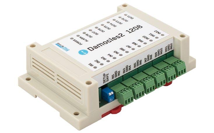
5 Connectors Ethernet Ethernet 100Base-Tx (10/100Mbit). When connected, the green Link LED at the connector lights up to indicate proper connection. When communicating, the yellow Activity LED flashes. Power The green LED indicates that the device is powered. Upon request (and under a different product code), models other than 2404 can be also equipped with PoE (Power over Ethernet). Inputs INx dry contact inputs. Inputs always share a common ground (). The corresponding green LED indicates a closed contact. Outputs MINI OUTx relay outputs with NO/NC contacts. When idle, NCx (Normally Closed) + COMx (Common) are connected. When activated, NOx (Normally Open) + COMx are connected. Yelow LED indicates an activated output OUTx relay outputs with NO/NC contacts. When idle, NCx (Normally Closed) + COMx (Common) are connected. When activated, NOx (Normally Open) + COMx are connected. Yelow LED indicates an activated output open collector semiconductor outputs with a common ground (), for controlling external switching elements. Yelow LED indicates an activated output. For more information, see Open Collector 1208 only. First start First steps 1. Connecting the cables Turn the unit and note its MAC address that is printed on the label on the side. Set the switches: DIP1=Off, DIP2=Off. Connect the unit to the Ethernet (with a patch cable to a switch, cross-over cable to a PC), RJ-45 port. Plug the power adapter into an electricity outlet and connect it to the power connector. The green POWER LED lights up. If the Ethernet connection works properly, the LINK LED lights up after a short while, and then flashes whenever data are transferred (activity indication) 2. Configuring the IP address UDP Config HWg Config utility root directory of the supplied CD (Windows and Linux versions). Also available for download at -> Software -> UDP Config. Click the icon to launch HWg Config. The program automatically looks for connected devices. Automatic device discovery works only in the local network. Individual units are identified by their MAC addresses (on the label at the bottom). Double-click a MAC address to open a basic device configuration dialog. Alarm/Setup LED Red LED indicates device state: continuously on means Alarm (DI outside of the safe range), flashing means TCP or Serial Setup mode. DIP1/DIP2 switches DIP1 activates serial setup mode/restores factory defaults. To restore factory defaults, quickly toggle the switch 3 within the first 5 seconds after powering up the device. DIP2 safe mode activates HW protection of configuration settings. In Safe mode, parameters cannot be changed (online demo). Click for details 8 models First start 9
 Network mask Gateway IP address for your network Device name (optional) Click the Apply Changes button to save the settings.")
6 First steps 3. Configure the network parameters IP address / HTTP port (80 by default) Network mask Gateway IP address for your network Device name (optional) Click the Apply Changes button to save the settings. First steps 4. WWW interface of the device To open the WWW interface of the device: Enter the device IP address in a web browser Click the IP address in UDP Config Click the underlined IP address in UDP SETUP The WWW page displays current status of the device and its digital inputs Alternatively, you may use the following utilities to configure the IP address: HWg Config for Linux available for download at: Important To reset the device to factory defaults, toggle DIP1 several times within 5 seconds after applying power to the device. No configuration changes can be stored while DIP2=On. To change the IP address, set DIP2=Off. 10 First start First start 11
, HTTPS certificates SNMP/SNMP Trap configuration (ports and alarm recipients) Enabling Modbus/TCP communication")


7 of the device General setup General: General Setup: Security: SNMP: Modbus: GSM: Log & Time: Portal: Inputs: Outputs: Virtual Outputs: System: Overview of current readings IP address, DNS IP filter, security (username/password), HTTPS certificates SNMP/SNMP Trap configuration (ports and alarm recipients) Enabling Modbus/TCP communication Configuration and test Configuration and test when working with a remote SMS-GW Time configuration, NTP server Connection to a remote portal Control of inputs and alert parameters Control of outputs, setting of parameters Option to control outputs via a Poseidon2 and, B2B Firmware upgrade, save/restore configuration, etc. 1 General Device name, e. g. First floor 1 Note: For a detailed description, see the detailed web interface description (2nd half of the manual). 4 1 User-defined 2 Alarm 3 Action when value 4 MIB file for DI names thresholds out of range SNMP software Note: For a detailed description, see the detailed web interface description (2nd half of the manual). 12 of the device of the device 13

8 Security SNMP Changes SNMP protocol versions 2 5 destinations for SNMP Traps Note: For a detailed description, see the detailed web interface description (2nd half of the manual). 1 Filters for IP addresses which may access the device 2 Configuration of usernames and 3 HTTPS passwords for accessing the device certificates Note: For a detailed description, see the detailed web interface description (2nd half of the manual). 14 of the device of the device 15
9 GSM IP address of HWg-SMS-GW to use 2 Recipients for sending text messages (SMS) phone no s 1 This text is inserted at the beginning 2 Up to 5 recipients 3 4 Sends a test of the subject line of alarm s test result Note: We recommend to use HWg-SMS-GW3 for sending text messages. One central SMS gateway for all HW group devices in a single LAN. Periodic Status Settings Periodical Status when enabled, sends an with device status at the specified intervals. For example every 24 hours (1440 minutes). Alarm Reminder when active, sends periodic reminders that the device is in the Alarm state. For example every 15 minutes. To send , check: 1. Correct Gateway IP address 2. DNS server in the network settings 3. SMTP server and port 4. Authentication enabled, correct username and password 5. Spam filter for your mailbox is disabled 16 of the device of the device 17


 This configuration only applies to the communication between and the online portal.")
10 Log & Time Portal Press the button to manually synchronize 2 Interval for logging 3 Expected size time with the specified server measured values of recorded data 1 Message from 2 Enable connection 3 Click to connect 4 AutoPush the portal to the remote portal to the portal configuration Configures the communication with the portal using the HWg-Push protocol. is the active side and establishes the connection periodically and/or whenever a change in a sensor value exceeds the configured AutoPush value. Connection parameters for the portal are pre-filled. AutoPush configuration Whenever an input state changes, immediately connects to the portal and notifies the DI change. (In case of sensors, the change must exceed the AutoPush value.) This configuration only applies to the communication between and the online portal. Local alarm values are configured in the portal. For portal connection, check: 1. Correct Gateway IP address 2. DNS server in network settings 3. Correct Server Address of the portal 18 of the device of the device 19
 Active if Off Alarm when the contact is open (0 = Off) Disabled No Alarm 3 Reaction to digital inputs: Send a SNMP Trap Send an E-mail Send a SMS Nothing checked = no active alarm")


 Local Condition DO cannot be controlled over the Web, it is controlled by a condition. DO is read-only for all M2M protocols. Hysteresis in the sensor settings applies.")
11 Digital Inputs (DI) Digital Outputs (DO) Enter Digital Input name that will be shown in s, text messages or SNMP traps 2 Alarm contact status: Active if On Alarm when the contact is closed (1 = On) Active if Off Alarm when the contact is open (0 = Off) Disabled No Alarm 3 Reaction to digital inputs: Send a SNMP Trap Send an Send a SMS Nothing checked = no active alarm on the DI 1 Choose the output mode Manual mode: Output controlled over the WEB or M2M protocols Local Condition mode: Controls the output according to the specified input 2 Enter a DO name to show in s, text messages or SNMP traps 3 Pulse output timer [s]. By default, Pulse Timer = 0 for a standard output Pulse Timer When set, the output is activated only for a specified duration. Pulse Timer = 0 disables this function. For details, see the WEB interface description. notifies alarm activation/deactivation for each DI. format cannot be changed, except that inputs may have custom names. Yellow background of the line with a sensor or an input means that the safe range is exceeded but alarm notification is off. Connecting the inputs 0 (Off) 1 (On) Output mode: A) Manual DO can be controlled using the or externally using M2M protocols. DO cannot be used in thermostat mode local condition. B) Local Condition DO cannot be controlled over the Web, it is controlled by a condition. DO is read-only for all M2M protocols. Hysteresis in the sensor settings applies. In the Local Condition mode, outputs cannot be controlled over the WEB or using M2M protocols. On if any alarm DO = On, if at least one input or sensor is in alarm. On if value equal to Trigger DO = On, if the selected sensor reading is equal to the Target Value. On if value higher than Trigger DO = On, if the selected sensor reading is higher than the Target Value. On if value lower than Trigger DO = On, if the selected sensor reading is less than the Target Value. On if alarm on DO = On when a particular sensor or input is in the Alarm state. Dependent On sensor/input to which the condition applies. 20 of the device of the device 21

.")
12 Virtual Outputs (VDO) System Restores factory 2 Uploads new firmware defaults from the PC Configuration Download download the configuration from the device to the PC. Upload restore the configuration from the PC to the device. Note: Configuration changes must be confirmed by clicking the Apply Changes button. Virtual Outputs allow the use of outputs of other Poseidon2 or units (Box2Box). The communication uses the TCP protocol and updates take place every 60s. For more information, see Virtual Outputs. 22 of the device of the device 23
 if it is closed for more than approx. 900ms (inputs are sampled approximately every 30 ms because of S0).")
, the alarm is not notified and the corresponding line is highlighted in yellow at the first page (General).")
13 Common features of the family Displayed readings displays current values of all digital inputs (DI). Inputs feature pulse counters for connecting energy meters with S0 outputs. An input is considered active (for Alarm state purposes) if it is closed for more than approx. 900ms (inputs are sampled approximately every 30 ms because of S0). Alarm state can be set independently for each input (contact). If the Alarm is not assigned to any channel (SMS, , SNMP Trap), the alarm is not notified and the corresponding line is highlighted in yellow at the first page (General). Upon Alarm, the device can send a SNMP Trap, , or SMS. notifies both the beginning and the end of an alarm (contact closing and contact opening). Supports a shared HWg-SMS-GW3 gateway for texting. Supports SNMPv1 and SNMPv3. Supports authentication via TLS. Supported interfaces (in detail) DI (Digital Inputs) Dry contact Inputs Dry (voltage-free) contacts can be connected to these terminals. For example door contacts. The inputs are electrically connected to the power supply. Unconnected inputs read as 0 (Off). Activated inputs (closed contacts) read as 1 (On), resistance against the Common pin must not exceed 500 Ω. Specifications: Maximum wiring length: 50 m Supported sensors: Any contact without external voltage (dry contact) Alarm settings for each DI: Alarm inactive Alarm when the contact is open or closed Alarm when the contact is open Possible alarm responses: Common setting for all inputs No response Alarm alert sent as a SNMP trap Alarm alert sent by or text message (SMS) Alarm alert sent as a SNMP trap as well as by or SMS Polling period: approx. 900 ms Range of sensor IDs: DI (Digital Inputs) use ID addresses from 1 to 24 Input names: Each DI can be named using up to 12 characters Disconnected detector indication: None, disconnected detectors read as O (Off) DO (Digital Outputs) units feature various types of digital outputs: MINI Relay 1208 Open Colector 2404 Relay Relay Output Each output controls two relay contacts: one Normally Open (NO) contact (open when the power is off and after startup), and one Normally Closed (NC) contact (closed when the power is off and after startup). Contact state (closed / open) is indicated by the corresponding LED. NO 29 COM 30 Power 12V Power NC COM NO The picture shows an example of connecting a 12 V light bulb, powered from the same source as the unit and controlled by the Normally Open contact of output No Common features of the family Supported interfaces (in detail) 25
14 Open Collector 1208 only Open collector outputs with common overvoltage diode protection. Outputs are protected with internal diodes against voltage spikes (e.g. from relay coils). Maximum load: 50 V, 500 ma per output, max ma total for all outputs Output names: Each output can be named using up to 12 characters State names: Output state (On and Off) can be named with up to 6 characters (e.g. Fuel Tank 14 Full / Empty ) Output devices can be powered from the same power supply as Damocles, or from another source. It is necessary to connect the power for external devices accordingly: User interface HWg Config HWg Config is a freeware utility for finding devices, assigning IP addresses and changing network settings over the Ethernet. Windows and Linux version IP address is assigned to a product with a specific MAC address No installation is necessary, simply run the EXE file Provides a clear overview of device names and parameters A Connecting the outputs internal power supply B Connecting the outputs external power supply +Ucc OUT1 DC POWER SUPLY 9 30 V +Ucc OUT1 DC POWER SUPLY MAX. PEAK 50 V / 500 ma OUT8 OUT8 +Vcc +Vcc 22k 22k +Vcc +Vcc 22k 2 22k 2 Connecting 1208 units (OC outputs) to Poseidon2 (DI inputs) +Ucc DAMOCLES OUT1 OUTxx INxx +Ucc 22k 22k +Vcc +Vcc POSEIDON Main features Concise graphical environment Device name, type, MAC address, IP address and communication port is displayed after a device is found Compatible with all HW group products (Poseidon, Damocles, PortBox, PortStore, I/O Controller, IP relay and other product lines) Windows and Linux versions available Displays current network settings of your computer Checks if the IP address is in use before assigning it Single-click access to the device web page Ability to open a Telnet session for TCP Setup Ability to restore factory defaults Detailed program description as well as an instructional video clip are available on the CD supplied with the device, or at our website: 26 Supported interfaces (in detail) User interface 27
.")

15 Main communication interface offers a simple and user-friendly graphical WWW interface. Besides displaying current readings, the interface provides access to complete device configuration and management, including network settings, sensor configuration and alarm responses (SNMP traps). To access the web interface, enter the IP address into the URL field of your browser and press Enter: General Inputs This section displays current states of dry contact inputs, including alarm states and settings. Active alarm is indicated by a red background of the corresponding line. Name Textual name of the input, assigned by user at the Inputs tab. ID Unique input ID number, as marked on the unit. Current Value 0 (Off) Open contact. 1 (On) Closed contact. Alarm Alert List of alarm settings for each input (triggered by values out of safe range). Line background color: White / no color = Input is not in alarm. Red = Input is in alarm. Yellow = Alarm is disabled for this input but the value is out of the safe range. Counters Damocles inputs feature pulse counters. This can be used for example to read energy consumption meters with a pulse output (S0). Counters are incremented whenever the input is closed. The pulse must be longer than 20 ms to be registered. Outputs Displays current output states, including their modes. Name Textual name of the output, assigned by user at the Outputs tab. ID Unique output ID number, as marked on the unit. Current Value 0 (Off) Output is idle (open, that is COM + NO connected). 1 (On) Output is active (closed, that is COM + NC connected). Mode Output mode, configured at the Outputs tab. Other information Terminal Configuration (TCP Setup) Link containing the IP address and the port to open a terminal session for TCP Setup. MIB links to the SNMP definition file. (right-click the link and select Save Target as to save the file to disk). OID SNMP Object Identifier, contains the list of most frequent SNMP OIDs. (right-click the link and select Save Target as.. to save the file to disk). XSD links to the XML definition file for values.xml. (right-click the link and select Save Target as to save the file to disk). Text and link For more information try Customizable link to the supplier or service provider. The text can be changed in TCP Setup, see the detailed description of TCP Setup. Note: The design of the main page can be changed only after consulting the manufacturer; we offer a Customization program. For more information, please contact your dealer. The main page with the overview of DI and DO states automatically reloads at configurable intervals (by default every 10 seconds, can be changed easily)
16 General Setup Network settings of the device: Network parameters, trusted IP address range, temperature units, output states, etc. Network Settings This block configures the main network parameters for Ethernet communication: IP address IP address of the unit. After a change, the device needs to be restarted. Submask Local network mask. After a change, the device needs to be restarted. Gateway Default gateway. After a change, the device needs to be restarted. Primary DNS/Secondary DNS Primary and secondary DNS server settings. Gateway needs to be set correctly for correct operation. HTTP port Port for communication using the HTTP protocol. Default is 80. HTTPS port Port for communication over the HTTPS protocol. Default is 443. TCP Telnet Setup Port for the terminal telnet setup mode. Default is 99. DHCP Client Activates automatic network configuration using a DHCP server. Enabled by default. A DNS server is necessary for converting domain names to IP addresses. Without a correctly configured DNS server, the following functions will not work: Time sync (SNTP), used in s and SNMP traps to timestamp events ing (SMTP) Logging of values with timestamps IPV6 This block groups options for operation in networks that support IPv6. Enable IPV6 Enables IPv6 support. Autoconfig IP parameters Enables automatic network configuration using SLAAC. Link Local Address Link address of the device only visible from the local network. IP Address / Prefix length Global (public) IP address and network prefix. Consists of the link address and the network prefix. Gateway Default gateway. After a change, the device needs to be restarted. Primary DNS/Secondary DNS Primary and secondary DNS server settings. Gateway needs to be set correctly for correct operation. Device name Name assigned to a particular device. This name is shown in all overviews along with the IP address (UDP Config); it is used as the sysname variable in SNMP. Other Settings and Information Syslog IP Address Syslog server address only for HW group debugging purposes. HW Security Protection A DIP switch that prevents any changes in the device configuration. Outputs: Values of outputs can be changed. Configuration: No changes are permitted. The protection status is displayed in the bottom left-hand corner. When the HW Protection is active, any configuration changes, including changes of the output states, are ignored. This mode is useful when connecting to a publicly accessible network. Note: Any changes must be confirmed by clicking the Apply Changes button. A successful change is indicated by an animation in the status bar next to the Apply changes button. Counters Resets the counter states at all device inputs see Inputs. Resetting the device also resets the coutners

17 Security Security settings. Restrictions in individual modes are shown in the following table. Lines indicate the method of accessing the device over IP, columns specify the restrictions resulting from the respective security settings. No restrictions (default) HW protection DIP = On Read only User Password IP Access filter SNMP Communities Read + Outputs Read & Write HTTP SNMP Comun1 Comun2 Web index (General) yes yes yes yes yes filtered Other pages R/W R R R/W** R/W filtered Values.xml R R R R R filtered Setup.xml R/W R R R/W** R/W filtered SNMP get (next) R R filtered R* R* SNMP set W no filtered [R*/]W* [R*/]W* Modbus/TCP R/W R TCP setup yes no no no yes UDP config R/W R FW update yes no no no yes filtered M2M outputs R/W R/W R R/W R/W * R and/or W must be enabled on the SNMP Setup tab by checking appropriate boxes. W** Only outputs can be changed, nothing else. Even the output mode cannot be changed. Note: The No restrictions column reflects the default configuration (see also the screenshots). That is, HW protection DIP=Off, no password set, IP Access filter set to / IP Access Filter Allows defining a range of trusted IP addresses that are allowed to access over HTTP and SNMP. The IP range is configured separately for each protocol. To set up the filter, specify the base IP address and the mask that define the trusted range according to the formula below (AND is bitwise multiplication). Access is granted if the condition is true. (IP trying to access AND Mask Value) = IP Address Value IP Filter settings Access granted from to Note IP address value Mask value Only one IP allowed Only one IP allowed allowed addresses All 256 addresses x and One address but on two networks addresses allowed 32 33
. Read & Write can perform any changes.")

.")

18 User Passwords Two separate user accounts (username and password) can be set up for SNMP and HTTP access. Account types: Read Only can only read values and configuration settings. Read Only + Outputs can read values and set outputs, cannot change configuration settings (not even input names). Read & Write can perform any changes. After setting up a username and a password, you will be asked to log in every time you try to open the. Passwords also apply to access to /values.xml and /setup.xml see the table. SNMP The SNMP Setup tab allows you to configure the settings for communication with the device using the SNMP protocol. The page content is slightly different for SNMPv1 and SNMPv3. See below. SNMPv1 In case of Read Only user for HTTP access, you will no longer be able to change configuration settings in the web interface. What to do if you forget your password Restore the factory-default configuration of the device by one of the following methods: Use the UDP Config utility (must run on the same network segment). Right-click the line corresponding to the device and select Load defaults from the pop-up menu. Use the DIP Load defaults feature. Toggle DIP1 several times during the first 5 seconds after powering up the device. HTTPS Server Certificate files Used to manage certificates needed for the HTTPS server. Allows you to upload or delete a public key, a private key, or a certificate of the certificate authority (CA) that has issued the public key certificate. General SNMP Settings SNMP port Communication port to use for the SNMP protocol [161]. SNMP Port Listener Port for receiving SNMP traps from Poseidon and Damocles devices in Box2Box communication mode [162]. SNMP Version SNMP protocol version setting [1]. SNMPv3 is recommended for secure communication enable it here. SNMP Access Defines names and access rights for groups of users that can work with the Damocles device. Community Textual name of the authorized group (usually Public and Private). Read The community is authorized to read variables over SNMP. Write The community is authorized to write values to variables over SNMP


![SNMPv3 When the SNMP version is changed, the SNMP parameter interface also changes. General SNMP Settings SNMP port Communication port to use for the SNMP protocol [161].](/docs-images/82/85502966/images/19-3.jpg "SNMP Port Listener Port for receiving SNMP traps from Poseidon and Damocles devices in Box2Box communication mode [162]. SNMP Version SNMP protocol version setting [3].")

19 SNMP Trap Destination Destinations for sending SNMP Traps. Community Textual name of the group for the SNMP trap being sent. IP address Destination address where the SNMP traps are sent. Port Destination port where the SNMP traps are sent. SNMP Communities Community Textual name of the security group. MIB II System Group User-defined data in the standard SNMP header. SysContact Contact information of the system administrator, e.g. an address. SysName Same as the device name. SysLocation Location of the unit, e.g. IT room, floor 2. Note: Any changes must be confirmed by clicking the Apply Changes button. A successful change is indicated by an animation in the status bar next to the Apply changes button. SNMPv3 When the SNMP version is changed, the SNMP parameter interface also changes. General SNMP Settings SNMP port Communication port to use for the SNMP protocol [161]. SNMP Port Listener Port for receiving SNMP traps from Poseidon and Damocles devices in Box2Box communication mode [162]. SNMP Version SNMP protocol version setting [3]. SNMP Access Defines names and access rights for groups of users that can work with the Damocles device. User name Textual name of the authorized group (by default Public and Private). Read The community is authorized to read variables over SNMP. Write The community is authorized to write values to variables over SNMP. SNMP Trap Destination Destinations for sending SNMP Traps. User name Textual name of the group for the SNMP trap being sent. IP address Destination address where the SNMP traps are sent. Port Destination port where the SNMP traps are sent. Enable SNMP traps are sent to this destination. SNMP Users Usernames and passwords for SNMPv3 communication. User name User name. Auth. Type Cipher type for user authentication. Available options are MD5 and SHA. Auth Password Password for user authentication. Privacy Type Cipher type for encrypting the communication. Available options are DES and AES. Privacy Password Password (key) for encrypting the communication. MIB II System Group User-defined data in the standard SNMP header. SysContact Contact information of the system administrator, e.g. an address. SysName Same as the device name. SysLocation Location of the unit, e.g. IT room, floor 2. Note: Any changes must be confirmed by clicking the Apply Changes button. A successful change is indicated by an animation in the status bar next to the Apply Changes button
.")
20 Modbus Note: The Modbus/TCP protocol is not secured in any way. We do not recommend using it outside of an isolated network. For basic security, it can be combined with the IP address filter. SMTP Server Host name or IP address of the SMTP server. SMTP Port Port for communication with the SMTP server (25 by default). Sender Address address that will be shown in the From field. Authentication Enables username/password authentication if the SMTP server requires it. Secure TLS mode Activates SSL/TLS authentication (e.g. for gmail). Name Username for authentication with the SMTP server. Password Password for authentication with the SMTP server. Subject Text Subject of the s sent, followed by the default text (see format). Alarm Recipient address of the main recipient (To). Alarm Copy address of the carbon-copy recipient (Cc). Periodic Log Recipient address of the recipient for periodically ed logs. Send Test button sends a test
21 Tip: It is not always necessary to configure a SMTP Server in order to send s. can work as SMTP server itself and deliver the s directly to the user s mailbox. However, always test this mode in your particular environment the s sent in this mode are often blocked by various spam filters due to missing reverse MX records. can only send s, it cannot receive them. is sent upon every alarm activation and deactivation. Sending a test Multiple systems need to be configured correctly in order to send s from the device successfully. Therefore, it is advisable to double-check the following parameters: Gateway in the network settings. DNS server in the network settings. SMTP server and port. Authentication turned on, correct name and password. Spam filter of your mailbox turned off. Received example: DATE TIME Device_NAME Device_IP :42: initiated: Test ID SENSOR_Name VALUE UNIT Safe_RANGE ALARM ALARM state: Binary 1 ON if ON Sensors list: Binary 1 OFF Disabled 2 Binary 2 OFF Disabled 3 Binary 3 OFF Disabled 4 Binary 4 OFF Disabled 5 Binary 5 OFF Disabled 6 Binary 6 OFF Disabled 7 Binary 7 OFF Disabled 8 Binary 8 OFF Disabled 9 Binary 9 OFF Disabled 10 Binary 10 OFF Disabled 11 Binary 11 OFF Disabled 12 Binary 12 OFF Disabled 123 Comm Monitor 1 OFF Disabled 151 BinOut 1 OFF Manual 152 BinOut 2 OFF Manual 153 BinOut 3 OFF Manual 154 BinOut 4 OFF Manual 155 BinOut 5 OFF Manual 156 BinOut 6 OFF Manual 157 BinOut 7 OFF Manual 158 BinOut 8 OFF Manual 1151 VirtBinOut 1 OFF Manual 1152 VirtBinOut 2 OFF Manual 1153 VirtBinOut 3 OFF Manual 1154 VirtBinOut 4 OFF Manual 1155 VirtBinOut 5 OFF Manual 1156 VirtBinOut 6 OFF Manual 1157 VirtBinOut 7 OFF Manual 1158 VirtBinOut 8 OFF Manual : 00:0A:59:04:40:E GSM SMS Interface Sekce Serial Port Settings Port Function sets the serial port function (only for models with a serial port and the netgsm server side feature). 3 options are available: Disabled Serial port is off. Only if no modem is connected and the device works as the client side. GSM modem A GSM modem is connected, and also acts as a netgsm server. Remote SMS gateway Configures the IP address, HTTP port and path to the service for sending SMS requests. For, the path is always service.xml. Tip: For detailed description of the format, see the Using units in your programs section:
22 GSM SMS interface Configures the parameters for sending text messages. GSM Function Selects whether SMS are sent through a local modem (only available if the serial port is in GSM Modem mode). SMS+Ring when Alarm Enables sending a SMS and then dialing the number. RS-232 GSM module (only for 2404 with a RS-232 modem connected) Indicates if the GSM modem is ready. Not Enabled Modem inactive. Shown after changing RS-232 port configuration but before saving it. Not Found is configured for a locally-connected GSM modem but the modem was not found. Waiting for modem Looking for the modem. Initializing The modem is being initialized. Ready The modem is ready. SMS center Number (only for 2404 with a RS-232 modem connected) Provider s SMS center number, as read from the SIM card. If the number has not been read, it is not possible to send SMS. GSM modem (local or remote) Sekce GSM SMS recipients Configures the numbers of SMS recipients, regardless of the mode of operation (local/remote modem). Send test SMS Send a test SMS to all configured numbers. RingOut Test Dials all configured numbers. SMS example: Alarm ACTIVATED, 2404, Binary 10, ON Device name: 2404 Inputs/outputs in alarm: Binary 10 = input name ON = alarm state, OFF = idle state Tip: For detailed description of the SMS format, see the SMS interface description in the Using units in your programs section. Note: Any changes must be confirmed by clicking the Apply Changes button. A successful change is indicated by an animation in the status bar next to the Apply changes button. Text messages (SMS) can be sent in two ways: A) Remote GSM modem does not have its own GSM modem. Serial Port Settings is set to Disabled. To send a SMS, a GSM modem connected to another unit or the HWg-SMS GWx product is used. The remote GSM modem must be accessible over the network, via an A address, by default at port 80 under service.xml. B) Local GSM modem (only for 2404 with a RS-232 modem connected) A GSM modem is connected to the RS-232 interface of. The modem is powered from its own adapter or from the 12V terminals. An activated SIM is inserted in the modem, PIN is disabled. SMS Center should be retrieved from the SIM after start-up. SOAP protocol is used for communication. If the connection is not established or is refused, tries to send the SMS again. The throughput of the remote GSM modem is limited to 5 SMS per minute for units and about 20 SMS per minute for SMS GW
, the device attempts to synchronize the time approximately once per hour until successful. SNTP Server IP address or host name of the SNTP server to synchronize the time with.")
23 Log & Time Date, time, and data logger configuration. Time Synchronization SNTP server settings for time synchronization. If the time is not set (the date is displayed), the device attempts to synchronize the time approximately once per hour until successful. SNTP Server IP address or host name of the SNTP server to synchronize the time with. Time zone Set the offset of your time zone against the SNTP server time. SNTP servers use UTC time, which is nearly equivalent to GMT (London time). Hence, for Paris, Berlin, Prague, and other locations within the same time zone, set +1 hour. Interval Specifies how often the time is synchronized with the time server. A shorter interval can achieve higher time accuracy, and works around certain managed switches that disconnect ports when there is no active communication. Note: The clock does not run when the device is powered off. The device contains no battery. After a power failure, the time will be synchronized with the SNTP server. Data Logger Settings Configuration parameters for logging values to a circular buffer within the internal flash memory. When the buffer is full, the oldest values are overwritten with the newest ones. Log Period Period of logging into the logfile for all values. Logfile capacity XXX The capacity estimate is given in days, hours and minutes. calculates the capacity based on the number of DI inputs. Caution: When the circular buffer is full, the remaining capacity shown will be zero. Clear the buffer to find out the total capacity. Report Log Period Period for ing the log. Erase log after The log is cleared after it is ed. This reduces attachment size and can speed up data transfer. Open log File button Stores the current logfile to disk by calling the external /spilog.txt file. Clar log File button Clears all values from the logfile by calling the external /spilog.del file. Note: Any changes must be confirmed by clicking the Apply Changes button. A successful change is indicated by an animation in the status bar next to the Apply changes button. Date and Time Current date and time settings. Current Date Date in the [dd.mm.yyyy] format, for example: Current Time Current time in the 24-hour [hh:mm:ss] format, for example: 17:38:55. The time updates automatically while the browser window is open. It is only saved when the Apply Changes button is clicked

24 Portal Portal Message section Information from the portal, such as links to graphs. Depends on the portal type. Portal Portal enable Turns this feature on or off. Server address Complete URL of the remote server. IP Port Port where the portal listens. User Name Username for assigning to a user. You will receive it from your portal administrator. Password Password for assigning to a user. You will receive it from your portal administrator. Current Push Timer Indicates the remaining time before the next standard data upload. Current Log Timer Indicates the remaining time before the next caching of data. Current Check Timer Indicates the time remaining until the next Check Push (to check if an output state change is requested). Current Autopush Block Timer Indicates the delay from one AutoPush upload to the next. The period is configured from the portal. Retransmit number Number of retransmissions if a Push fails. Manual Push Button for immediate manual upload of data to the portal. AutoPush configuration connects to the portal immediately and notifies a change of an input state (at most 30 s from the last change). This configuration only applies to the communication between and the online portal. Local alarm values are configured in the portal. For portal connection, check: 1. Correct Gateway IP address 2. DNS server in network settings 3. Correct Server Address of the portal Configures the communication with the portal using the HWg-Push protocol. is the active side and establishes communication periodically and upon every DI change. Connection parameters for the portal are pre-filled
. Username User name for logging in to the MQTT broker.")
 prefix. Inputs Topic Name Corresponds to the input name at the Inputs tab.")
25 MQTT Used to connect to an IoT network using the MQTT protocol. MQTT Settings section MQTT Enable Enables or disables data transfer using the MQTT protocol. Server IP address or domain name of the MQTT broker server. Port TCP port where the MQTT broker listens (default is 1883, or 8883 for SSL). Username User name for logging in to the MQTT broker. Password Password for logging in to the MQTT broker. Secure SSL mode Enables or disables SSL support when communicating with the MQTT broker. Client ID Device ID in the MQTT network. Publish Period Frequency of sending data to the MQTT broker. Topic Prefix Name MQTT Topic (adress) prefix. Inputs Topic Name Corresponds to the input name at the Inputs tab. ID Corresponds to the input ID at the Inputs tab. Publish Enables or disables the sending of information about a particular input. Topic Name = value Complete Topic after the prefix: x/value Current input value. x/state Current input status. x/counter Current counter status. Outputs Topic Name Corresponds to the output name at the Outputs tab. ID Corresponds to the output ID at the Outputs tab. Publish Enables or disables the sending of information about a particular output. Topic Name = value complete Topic after the prefix: x/value current input value. For more information about MQTT and its use, see ANXXX at the HW-group.com website
.")
26 Digital Inputs (DI) Parameters for DI (Dry Contact Inputs). Damocles inputs feature pulse counters; this can be used for example to read energy consumption meters with a pulse output (S0). Counters are incremented whenever the input is closed. The pulse must be longer than 20 ms to be registered. Counters are 32 bit (maximum value ). Values are retained in memory even when the power is off. They can be reset (for the entire device) at the General Setup tab. Name Name of the input, up to 12 chars (e.g. left door, smoke room 1 ). ID Unique ID of the input variable within the device [1 32]. Current Value Current state of the input ( O (Off) / 1 (On) ). Alarm State Alarm state definition for each input. Active if On Alarm is active whenever the input is in 1 (On). Active if Off Alarm is active whenever the input is in 0 (Off). Disabled Input has no alarm state defined. Delay [s] Delays the sending of information about alarm beginning and alarm end. Out of Safe Range Response to the Alarm state activation/deactivation for dry contact inputs. SNMP Trap Enables sending a SNMP trap upon alarm activation/deactivation. Enables sending an upon alarm activation/deactivation. SMS Enables sending a SMS upon alarm activation/deactivation. Note: SMS (text messages) are sent through a GSM modem connected directly to the unit via the RS-232 interface (see the list of models), or via a remote HWg-SMS-GW3. The Alarm state for each DI is only active when assigned to an action (sending an , SMS or SNMP Trap). Nothing checked = no active alarm for the DI input (yellow status in the table at the home page). It is recommended to activate SNMP Trap to notify alarms. Alarm START notification Alarm START notification Alarm END notification Alarm END notification Alarm START notification Alarm END notification Alarm state Delay [s] Time Alarm status notification based on a Delay value: Blue: Delay = 0 Yellow: Delay is set 50 51
.")
27 Digital Outputs (DO) Controls the outputs and configures their modes. Output Control Manual Output controlled over the web or M2M protocols (XML, SNMP...). Change to On/Off Change output state (after confirming with Apply Changes). Local Condition Output is controlled using a condition and a sensor. The output state is read-only for M2M protocols (output cannot be controlled). The control is linked to the Target Value, hysteresis is used (IDLE Range) as configured for the sensor. On if any alarm The output is closed if at least one of the inputs or sensors is in alarm. Caution: This condition also takes into account the DELAY and HYSTERESIS settings for individual active sensors and inputs. On if alarm on The output is closed whenever there is an Alarm at the selected sensor (input). On if value equal to Trigger The output is closed if the value matches the Target Value setting. On if value higher than Trigger The output is closed if the Current Value is greater than the Target Value setting. On if value Lower than Trigger The output is closed if the Current Value is less than the Target Value setting. Trigger Value Trigger threshold for the condition (e.g. output is activated if the value is higher than the Trigger Value). Dependent On Selection of a sensor to which the condition applies. Basic parameters ID Unique ID of the output within the device [ ]. Current Value Current state of the input ( 0 (Off) / 1 (On) ). Name Name of the output, up to 12 chars (e.g. top fan, Door rack 4 ). ON (Closed) Name Name of the 1 (On) state e.g. closed, flooded, activated etc. OFF (Open) Name Name of the 0 (Off) state e.g. open, inactive etc. Pulse timer Activates the input (switches to 1 (On) state) only for the defined period. To reverse the function, use the NO/NC relay output. When Pulse Timer = 0, the pulse function is disabled (default). The pulse also applies to the local condition. The pulse width applies from the beginning of the local condition (safe value exceeded). There is only one pulse per satisfaction of the condition


28 Virtual Outputs (VDO) Virtual Outputs allow the use of outputs of other Poseidon2 or units (Box2Box). The communication uses the TCP protocol and updates take place every 60 seconds. For details, see ANXX. System Communication monitor Monitors whether communication with over selected protocols takes place, and if it doesn t within the specified time, a virtual Comm monitor input is activated. Configuration Save Configuration Stores the setup.xml file with device configuration to your HDD. Load Configuration Uploads a XML file with the configuration from your PC. ID Unique ID of the output within the device [ ]. Virtual Type Enables the virtual output functions. Name Name of the output, up to 12 chars (e.g. top fan, Door rack 4 ). Remote device address IP address of the remote side where the output is controlled. Port TCP port where the remote side listens. Remote port ID Output ID at the remote side. Corresponds to the ID at the Outputs tab at the remote side. Username/Password If the remote side uses SW protection against unauthorized use, enter the Read & Write or the Read & Outputs password. System Uptime Time of uninterrupted device operation (since last restart). Set Default Config Restore factory-default settings. Restart device Restarts the device. Update FW Loads a.hwg firmware file from your PC to the device


29 Updating Firmware Updating the firmware over the WEB Upload the firmware in a.hwg file over http to Connection interruption must be avoided during file transfer. If the update fails, upload the firmware over RS-232 as described above. Firmware in the.hwg format is available at the Damocles website, or on the supplied CD. Software Applications HWg-PDMS Windows application that logs data from all HW group devices into its internal database. The application runs in the background (NTservice). Data is retrieved from the devices over http or . Data can be exported over XML or automatically stored to MS Excel. License: Free HWg-PDMS version for 3 sensors. Paid versions for 8/20/200/ unlimited sensors (DI inputs). Caution: Please contact us in case of any problems with firmware upload. HWg-Trigger Windows application for detecting and reacting to events. Detects, for instance, disconnected devices, failed sensors, values out of range, or incoming SNMP Trap alerts. Possible responses include sending an , activating a relay over the network, or sending a text message (SMS) using HWg-SMS-GW. Other responses include displaying a warning message in Windows, starting an application, or shutting down the computer. License: 30-day trial version free of charge. 56 Software Applications 57


30 SensDesk.com Online portal for collecting data from LAN and GSM sensors. can connect to the SensDesk internet service. All devices can be managed from a single WWW interface. Watch sensor states, display your devices in a map, compare trends in time and analyze alarm messages. SensDesk is a way to implement fully functional monitoring of customer technology in a matter of minutes, with fixed costs of the system. No need for installing a complex system or adding another server at the customer side. PosDamIO and SDK Poseidon Damocles I/O is a command-line utility for Windows and Linux that lets you control Poseidon and Damocles units over the XML interface. It can display the states of sensors, inputs and outputs, as well as set an output high or low. HWg SDK is a library of functions, as well as examples of their use, for Unix and Windows. The functions are intended to help third-party SW solutions communicate with our products over IP. SDK reduces the time needed to implement support for our products into your SW. For more information: Overview of all sensors at a single place. Centralized alarm configuration for individual sensors. Mobile application for monitoring. Remote configuration of GSM devices. can be connected to the sensdesk.com portal similarly to Poseidon2 devices Software Applications Software Applications 59
31 Specifications MINI dimensions Power 9 30V MINI specifications Ethernet Interface RJ45 (100BASE-Tx) 10 / 100 Mbit Supported protocols ARP, ICMP, UDP / IP: SNMP, TCP / IP: HTTP, Modbus / TCP, SMTP, netgsm, HWg-PUSH, XML, IPv6, HTTPs, MQTT SNMP compatibility SNMPv1 + SNMPv3 compatible, partial support for v2.0 ETHERNET 120 mm 106 mm 100 mm Setup Safe +U DI Inputs (Dry contact inputs) Ports I1, I2, I3, I4 Type 4 Digital Input (for a voltage-free contact, such as a NO/NC relay contact, Dry Contact) Sensitivity 1 (On) = Ω (Up to 12 V can appear at the socket against ) Pulse counter 4 32-bit, min. pulse width 20 ms. Counter value is retained even after power disconnection. Max. distance Up to 50 m DO Outputs Type OUT1, OUT2 / Relay contacts (NC-COM-NO) Max. load Max. 2 A, up to 24 W (2 A / 12 V or 0.5 A / 48 V) Power on state Normal (no state memory) LED Power (RJ45) Green power OK Link & Activity (RJ45) Green physical connection established, Yellow flashes, communication taking place ETHERNET Input / Output Status Green input, Yellow output Power Setup/Alarm IN2 IN3 IN4 OUT1 OUT2 Alarm Setup DIP Switch DIP1: Setup DIP2: Security On Flashing ON Normal function mode Restoring factory defaults: Toggle the switch 3 during the first 5 seconds after powering up ON = Security mode configuration cannot be changed remotely OFF = Non-secure mode configuration can be changed remotely Parameters Power 9 30 V DC / 250 ma DC Power connectors 1 barrel jack (2.5 mm, outer diameter 6.3 mm) 1 terminal block Temperature ranges Operation: 30 to +85 C (+14 to +150 F) Storage: 35 to +85 C ( 22 to +185 F) Dimensions / mass mm / 300 g 31 mm 36,5 mm 73 mm 93,5 mm Inputs NC1 COM1 NO1 NC2 COM2 NO2 IN2 IN3 IN4 Outputs Power Out +U 60 Specifications Specifications 61
32 1208 dimensions 1208 specifications Ethernet SETUP SAFE ON 1 2 IN2 IN3 IN4 IN5 IN6 IN7 IN8 IN mm Interface RJ45 (100BASE-Tx) 10/100 Mbit Supported protocols ARP, ICMP, UDP / IP: SNMP, TCP / IP: HTTP, Modbus / TCP, SMTP, netgsm, HWg-PUSH, XML, IPv6, HTTPs, MQTT SNMP compatibility SNMPv1 + SNMPv3 compatible, partial support for v mm DI Inputs (Dry contact inputs) 4 ø5,3 mm Ports Type I1 l12 12 Digital Input (for a voltage-free contact, such as a NO/NC relay contact, Dry Contact) Sensitivity 1 (On) = Ω (Up to 12 V can appear at the socket against ) Pulse counter bit, min. pulse width 20 ms. Counter value is retained even after power disconnection. Max. distance Up to 50 m POWER ALARM OUT8 OUT7 OUT6 OUT5 OUT4 OUT3 OUT2 OUT1 DO Outputs 70 mm 90 mm Type Max. load 8 Open collector 50 V max. 500 ma / 1 output, max ma / all 8 outputs IN2 IN3 IN4 IN5 IN6 IN7 IN8 IN LED Power (RJ45) Green power OK Link & Activity (RJ45) Green physical connection established, Yellow flashes, communication taking place Input / Output Status Green input, Yellow output Alarm On 125 mm Setup Flashing 135 mm DIP Switch 145 mm DIP1: Setup OFF Normal function mode Restoring factory defaults: Toggle the switch 3 during the first 5 seconds after powering up DIP2: Security ON = Security mode configuration cannot be changed remotely OFF = Non-secure mode configuration can be changed remotely Parameters Power 9 30 V / 1.7 W DC Activity Link ETHERNET +U Power 9-30V OC1 OC2 OC3 OC4 OC5 OC6 OC7 OC8 Power connectors Temperature ranges 1 barrel jack (2.5 mm, outer diameter 6.3 mm) 1 terminal block Operation: -30 to +65 C (+14 to +150 F) Storage: -30 to +65 C (-22 to +150 F) Dimensions / mass mm / 222 g 62 Specifications Specifications 63
33 2404 dimensions 2404 specifications 100 mm Ethernet Interface RJ45 (100BASE-Tx) 10 / 100 Mbit Supported protocols ARP, ICMP, UDP / IP: SNMP, TCP / IP: HTTP, Modbus / TCP, SMTP, netgsm, HWg-PUSH, XML, IPv6, HTTPs, MQTT 45,5 mm SNMP compatibility SNMPv1 + SNMPv3 compatible, partial support for v2.0 Serial port 1 DB9M RS mm 8 mm Connector Pinout Usage Cannon 9 (DB9M) Standard IBM PC DB9M (RxD, TxD, RTS, CTS, ) Serial setup, N1 116 mm Max. distance 2 m DI Inputs (Dry contact inputs) NO4 COM4 NC4 IN24 NO3 COM3 NC3 IN20 IN21 IN22 IN23-48V -48V +U OUT1 OUT2 IN2 IN3 IN4 IN5 IN6 IN7 IN8 IN SECURITY SETUP 2 1 ON Status Alarm Link Power OUT3 OUT IN20 IN21 IN22 IN23 IN mm 179 mm NC2 COM2 NO2 NC1 COM1 NO IN9 IN8 IN7 IN6 IN5 IN4 IN3 IN2 +U Port I1 l24 Type 24 Digital Input (for a voltage-free contact, such as a NO/NC relay contact, Dry Contact) Sensitivity 1 (On) = Ω (Up to 12 V can appear at the socket against ) Pulse counter bit, min. pulse width 20 ms. Counter value is retained even after power disconnection. Max. distance Up to 50 m DO Outputs Type OUT1 OUT4 / Relay contacts (NC-COM-NO) Max. load Max. 2 A, up to 24 W (2 A / 12 V or 0.5 A / 48 V) Power on state Normal (no state memory) LED Power (RJ45) Green power OK Link & Activity (RJ45) Green physical connection established, Yellow flashes, communication taking place Alarm & RS-232 Setup Red flashing device in RS-232 Setup mode Alarm On Setup Flashing DIP Switch ON = RS-232 Setup mode on Port 1 (only RS-232 setup works) DIP1: RS-232 Setup mode OFF = Normal function mode Restoring factory defaults: Toggle the switch 3 during the first 5 seconds after powering up ø4,8 mm (2 ) DIP2: Security ON = Security mode configuration cannot be changed remotely OFF = Non-secure mode configuration can be changed remotely Parameters Power 1 Power 2 (PoE) Power 3 (-48V) Power connector 1 Temperature ranges Dimensions/mass 9 30 V / consumption approx. 250 ma / 12 V DC PoE (IEEE 802.3af) -48 V DC Telco standard (-30 V to -60 V DC) 1 barrel jack (2.5 mm, outer diameter 6.3 mm), + inside 2 terminal block (U+ / ) Operation: -30 to +65 C (+14 to +150 F) Storage: -30 to +85 C (-22 to +167 F) mm / 400 g 64 Specifications Specifications 65


34 Formats and interfaces HWg products XML interface description The XML format is identical for both Poseidon2 and devices. Modbus over TCP Interface description Note: For details about Modbus/TCP, see our website AN28: Damocles family & Modbus/TCP. HWg-netGSM remote SMS gateway protocol for HW group products For a current protocol description, see: SNMP Interface description SNMPv3 HTTPS in and Poseidon2 Poseidon2 3266/3268 The basic unit for monitoring temperature, humidity and other enviromental conditions across LAN. Poseidon Remote monitoring of temperature, humidity and other enviromental conditions in industrial design. Poseidon Unit designed for demanding monitoring applications, e.g. in data centers and industry. Ares 12/14 Remote surveillance of environment wherever there is GSM coverage. HWg WLD Unit for detecting flooding with detection over the entire length of the sensing cable. HWg PWR 3/12/25 Measures power consumption using external M-Bus meters. 66 Formats and interfaces
Poseidon MANUAL
 Poseidon2 3266 MANUAL Safety information The device complies with regulations and industrial standards in force in the Czech Republic and the European Union. The device has been tested and is supplied
Poseidon MANUAL
 Poseidon2 4002 MANUAL www.hw-group.com 2 Safety information The device complies with regulations and industrial standards in force in the Czech Republic and the European Union. The device has been tested
Poseidon 4002 MANUAL
 Poseidon 4002 MANUAL Poseidon 4002 MANUAL POWER input 12VDC supply (jack or terminals) INPUTS Binary inputs 1 6 (for contacts) OUTPUTS Two 50V rated switchover relay contacts ETHERNET 10 or 100/10 Mbps
Connector for sensing cable
 HWg-WLD MANUAL ETHERNET 10/100 Mbps Status LED Yellow: Power & Mode Green: Link & Activity Connection cable 100 m max POWER input 5V DC supply Use the supplied power adapter SENSOR Connector for sensing
HWg-STE HWg-STE PoE MANUAL
 HWg-STE HWg-STE PoE MANUAL HWg-STE connections LED indicators Green: Power & Mode Yellow: Link & Activity SENSORS S1 and S2 ports for connecting temperature or humidity sensors. - Max. distance with 1
HWg-SMS-GW manual. HW group. HWg-SMS-GW. SMS gateway for HW group products. 1
 HWg-SMS-GW SMS gateway for products www.hw-group.com 1 Recommended connection HWg-SMS-GW is a device that enables multiple devices to send alarm text messages (SMS) through a single GSM modem using the
Poseidon 2250 Short Manual
 Poseidon 2250 Short Manual www.hw-group.com 1 / 54 Safety information The device complies with regulations and industrial standards in force in the Czech Republic and the European Union. The device has
SNMP Web Management. User s Manual
 SNMP Web Management User s Manual Suitable Product: SNMP Web Card SNMP Web Box Management Software for Uninterruptible Power Supply Systems Table of Contents 1. Overview... 1 1.1 Introduction... 1 1.2
Table Of Contents. 1. Introduction... 1
 User Manual Table of Content Table Of Contents 1. Introduction... 1 1.1 Brief Introduction to Web Interfaces... 1 1.2 How to Log In... 1 1.3 General Setting... 2 1.3.1 Date and Time Setting... 2 1.3.2
Network Management Card. User Manual
 User Manual 1 Contents Contents 2 Chapter 1 Overview 3 1.1 NMC package contents 4 1.2 NMC CD Resources 4 1.3 Features 4 1.4 NMC Applications 5 Chapter 2 NMC parameters setting via serial COM port 6 2.1
proudly presents HW group Environment Monitoring Systems
 Sumpftrasse 32 6300 Zug Switzerland www.temperatur-sensor.ch proudly presents HW group Environment Monitoring Systems Jens Albrecht, B.S. EE CEO About HW group s.r.o company HW group produces IP sensors
Industrial Serial Device Server
 1. Quick Start Guide This quick start guide describes how to install and use the Industrial Serial Device Server. Capable of operating at temperature extremes of -10 C to +60 C, this is the Serial Device
EGW1-IA3-MB User s Manual
 www.exemys.com Rev. 0 1 Products are in constant evolution to satisfy our customer needs. For that reason, the specifications and capabilities are subject to change without prior notice. Updated information
LAN Interface TCW120B
 LAN Interface TCW120B 1. Short description TCW120 is a multifunctional device for remote monitoring and management. It is an Ethernet based controller, which is designed to work in IP-based networks and
ETHM-2. Ethernet Module. SATEL sp. z o.o. ul. Schuberta Gdańsk POLAND tel
 Ethernet Module ETHM-2 Firmware version 1.0 ethm2_en 09/08 SATEL sp. z o.o. ul. Schuberta 79 80-172 Gdańsk POLAND tel. + 48 58 320 94 00 info@satel.pl www.satel.pl SATEL's goal is to continually improve
User Manual PDUTracker
 User Manual PDUTracker Management Software for PDU Table of Contents 1. Overview... 1 1.1. Introduction... 1 1.2. Features... 1 2. Install and Uninstall... 1 2.1. System Requirement... 1 2.2. Software
Viewing System Status, page 404. Backing Up and Restoring a Configuration, page 416. Managing Certificates for Authentication, page 418
 This chapter describes how to maintain the configuration and firmware, reboot or reset the security appliance, manage the security license and digital certificates, and configure other features to help
IP Sensor IPS2222 User manual
 IP Sensor IPS2222 User manual Output LED indicators Power input 12VDC adapter 2 Relay outputs LED Indicators 1 wire 2 Dry 2 Analog Green : Power Yellow: Link temperature & humidity contact inputs inputs
Network Management Card. User Manual
 User Manual 1 Contents Contents 2 Chapter 1 Overview 3 1.1 NMC package contents 4 1.2 NMC CD Resources 4 1.3 Features 4 1.4 NMC Applications 5 Chapter 2 NMC parameters setting via serial COM port 6 2.1
PCE-IMS 1 User Manual IP Monitoring systems IP Switchable Metered PDU s
 PCE-IMS 1 IP Monitoring systems IP Switchable Metered PDU s System installation System setting Accessories Monitoring master unit Extension units Sensors SNMP server List of USB-cameras - 02 - Contents
Installation of the PCMeasure Movement Sensor (30114)
") 1. Hardware: Installation of the PCMeasure Movement Sensor (30114) Connect the sensor to a serial or parallel port of the PC using one of the PCMeasure adaptors, or directly to the PCMeasure Ethernet Box.
1. Hardware: Installation of the PCMeasure Movement Sensor (30114) Connect the sensor to a serial or parallel port of the PC using one of the PCMeasure adaptors, or directly to the PCMeasure Ethernet Box.
Ethernet controller TCW180 Users manual
 Ethernet controller TCW180 Users manual 1. Short description TCW180 is 8-Channel Ethernet relay board, which is designed to work in IP-based networks and managed by WEB interface or SNMP programs. This
RAMOS PLUS RACK MONITORING SYSTEM INTRODUCTION MANUAL
 RAMOS PLUS RACK MONITORING SYSTEM INTRODUCTION MANUAL EN Table of Contents Introduction... 3 What is the RAMOS PLUS and Rack sensor ST3H... 3 RAMOS PLUS Features:... 3 Port assignment information for RAMOS
3.1 Updating Web Package Updating OS... 16
 User Manual V1.0.0 Table of Contents Chapter1. Overview... 1 1.1. Specification... 1 1.2. Dimensions... 2 1.3. Connector pin designations... 4 1.4. Restoring factory default... 4 1.5. LED indicator...
REFERENCE GUIDE. Copyright ComAp s.r.o.
 IB-Lite Plug-in Ethernet module To be used with ComAp controllers: IL MRSXX, IL AMFXX, IL-NT MRSXX, IL-NT AMFXX, IC-NT SPtM, IC-NT MINT, MC-NT, ID-Lite and other controllers based on these platforms SW
Innovative Electronics for a Changing World INDEX
 Innovative Electronics for a Changing World INDEX 1. SYSTEM DESCRIPTION 2. BOARD CONNECTIONS terminals and indicators 3. CONNECTION DIAGRAM 4. START UP GUIDE and passwords 5. HOME PAGE 6. STATUS PAGE 7.
Release Note of RMCARD 202/203 Ver (Release Date: 06/09/2017):
:") Release Note of RMCARD 202/203 Ver. 2.29 (Release Date: 06/09/2017): Unexpected reboot when E-mail notification was executed via Office365 SMTP Server. Fixed the system not sending the login fail event
Release Note of RMCARD 202/203 Ver. 2.29 (Release Date: 06/09/2017): Unexpected reboot when E-mail notification was executed via Office365 SMTP Server. Fixed the system not sending the login fail event
Ethernet controller TCW180B Users manual
 Ethernet controller TCW180B Users manual 1. Short description TCW180B is 8-channel Ethernet relay board, which is designed to work in IP-based networks and managed by WEB interface or SNMP programs. This
INDEX. Network Power Monitor NPM-R10-SNMP. Innovative Electronics for a Changing World. NPM-R10-SNMP Remote Network Power Monitor
 Innovative Electronics for a Changing World NPM-R10-SNMP Remote Network Power Monitor Optional relay board and GSM module INDEX 1. SYSTEM DESCRIPTION 2. SYSTEM BATTERY CONNECTIONS 3. SERIES CONNECTED BATTERIES
Chapter 3 Managing System Settings
 Chapter 3 Managing System Settings Using the System Settings Utility The navigation pane at the top of the web browser interface contains a System tab that enables you to manage your FS700TSSmart Switch
User Manual. MPPTracker. Management Software for Solar Charge Controller. Version: 1.2
 User Manual MPPTracker Management Software for Solar Charge Controller Version: 1.2 Table of Contents 1. MPPTracker Overview... 1 1.1. Introduction... 1 1.2. Features... 1 2. MPPTracker Install and Uninstall...
User s Guide: Applied Functions
 User s Guide: Applied Functions Table of contents 1 Using Web Connection 1.1 Web Connection... 1-2 Web Connection...1-2 Operating environment...1-2 1.2 Operations required to use this function... 1-2 1.2.1
INDEX. Network Power Monitor R10 SNMP
 Innovative Electronics for a Changing World NPM-R10 Remote Network Power Monitor With optional relay board and GSM module INDEX Amended 21 March 2017: Add user defined Password see page 13 Add wire Connection
EP2 EP8 User Manual. Copyright 2007,ATAL
 EP2 EP8 User Manual Copyright 2007,ATAL 1) Introduction 1. What is EP? 2. What s the difference between the EP2 and the EP8? 3. How to use this manual 4. EP2 5. EP8 2) Installation 1. Assigning an IP address
256 MB RAM. 256 MB 32 bits RISC Cortex-A8 600MHz SD Card Slot. N/A USB Host. N/A USB Client
 User Manual V1.0.0 Table of Contents Overview... 1 1.1. Specification... 1 1.2. Dimensions... 2 1.3. Connector pinouts... 3 1.4. Restoring factory default... 3 1.5. LED indicator... 3 1.6. CR1225 battery...
1. General Description
 ipio-2, ipio-8, ipio-16 Monitor and Control of Digital I/O 1. General Description The ipio is a network attached, web enabled digital input and output device. The ipio can be controlled and monitored with
When an event such as a power failure or a low battery condition occurs,.netpower will notify users via the following ways:
 Introduction The.NETpower Card/Box is primarily used to provide a network management function for the UPS. After plugging it into the UPS, you can manage the UPS remotely via an SNMP NMS (Network Management
User's Guide Applied Functions
 User's Guide Applied Functions Table of contents 1 Using Web Connection 1.1 Web Connection... 1-2 Web Connection...1-2 Operating environment...1-2 1.2 Operations required to use this function... 1-3 1.2.1
Technical Manual Nova: Cabinet Security Management System (CSMS)
") Technical Manual Nova: Cabinet Security Management System (CSMS) KP_nova_TM_160501_EN 1 Publication May, 2016, Keyprocessor BV Paasheuvelweg 20 1105BJ Amsterdam, The Netherlands www.keyprocessor.com/nova
Technical Manual Nova: Cabinet Security Management System (CSMS) KP_nova_TM_160501_EN 1 Publication May, 2016, Keyprocessor BV Paasheuvelweg 20 1105BJ Amsterdam, The Netherlands www.keyprocessor.com/nova
Expert Power Control NET 4x DIN
 Expert Power Control NET 4x DIN 2009 Gude Analog- & Digitalsysteme GmbH 2009 Gude Analog- & Digitalsysteme GmbH 14.12.2009 Content 3 Table of contents 1 Security Advise 4 2 Description 5 3 Hardware 3.1
SNMP IPv6 for UPS. Save This Manual
 SNMP IPv6 for UPS Save This Manual This manual contains important instructions and warnings that you should follow during the installation, operation, storage and maintenance of this product. Failure to
HWg-Tg11 First steps for remote monitoring & logging via GSM/GPRS
 HWg-Tg11 Manual HWg-Tg11 First steps for remote monitoring & logging via GSM/GPRS Device description Power supply connector - RJ12 connector Device status indicators Red, Green, Yellow indicators Antenna
IPMI Configuration Guide
 IPMI Configuration Guide 1. Introduction of IPMI Server Manager... 2 2. IPMI Server Manager GUI Overview... 3 1 1. Introduction of IPMI Server Manager IPMI Server Manager allows remote access of computers
ROOM GUARD VT335. Environmental Infrastructure monitoring
 Environmental Infrastructure monitoring ROOM GUARD VT335 Environmental monitoring of any facilities, control of security breaches, temperatures, smoke, water leakages, voltages and more. Compatible with
Overview of the Cisco NCS Command-Line Interface
 CHAPTER 1 Overview of the Cisco NCS -Line Interface This chapter provides an overview of how to access the Cisco Prime Network Control System (NCS) command-line interface (CLI), the different command modes,
MobilTherm 2ad. 1. How the interface works: GSM temperature alarm module with auxiliay inputs and relay outputs
 MobilTherm 2ad GSM temperature alarm module with auxiliay inputs and relay outputs The MobilTherm-2ad is a GSM temperature and remote signaling module, designed for GSM based remote control, remote signal.
smartden IP-WatchDog PING Restarter and Auto-Rebooter
 smartden IP-WatchDog PING Restarter and Auto-Rebooter User Manual Date: For firmware version: v1.21 / May 2017-1- Content smartden IP-WatchDog User Manual 1. Features... 3 2. Application examples... 4
sensorprobe2 / sensorprobe8 User Manual
 www.akcp.com sensorprobe2 / sensorprobe8 User Manual Help Version updated till firmware 382L Copyright 2007, AKCP Co., Ltd.. 1) Introduction 1. What is sensorprobe? 2. What s the difference between sp2
Innovative Electronics for a Changing World. NPM-R10 Remote Network Power Monitor. With optional relay board and GSM module INDEX
 Innovative Electronics for a Changing World NPM-R10 Remote Network Power Monitor With optional relay board and GSM module INDEX 1. SYSTEM DESCRIPTION 2. BOARD CONNECTIONS terminals and indicators 3. CONNECTION
VT805 / Monitoring system
 Environmental Infrastructure monitoring VT805 / Monitoring system Environmental monitoring of any facilities, control of security breaches, temperatures, smoke, water leakages, voltages and more. Compatible
ECAN-240. (Modbus TCP to 2-port CAN Bus Gateway User manual) ECAN-240 Modbus TCP to 2-port CAN Bus Gateway User Manual, Version 1.0.
 ECAN-240 Modbus TCP to 2-port CAN Bus Gateway User Manual, Version 1.0.") ECAN-240 (Modbus TCP to 2-port CAN Bus Gateway User manual) ECAN-240 Modbus TCP to 2-port CAN Bus Gateway User Manual, Version 1.0.0 Page: 1 Table of Contents Table of Contents -----------------------------------------------------------------------------2
ECAN-240 (Modbus TCP to 2-port CAN Bus Gateway User manual) ECAN-240 Modbus TCP to 2-port CAN Bus Gateway User Manual, Version 1.0.0 Page: 1 Table of Contents Table of Contents -----------------------------------------------------------------------------2
Safety information. Table of contents. Device housing cannot be opened if the relay contacts are connected to a power network.
 HWg-SH4 User guide Safety information The device complies with regulations and industrial standards followed in Czech Republic and European Union. The device has been tested and is supplied in working
SMS Transceiver V3 User manual
 SMS Transceiver V3 User manual SMS Transceiver V3 - User manual ver. 1.8.3 - Fw: 3.0.7 - Sw: 1.6.2 Contents Page 1. Introduction 3 2. Connections 3 2.1 Inputs 3 2.2 Outputs 3 2.3 Power supply 3 2.4 Contacts
Intelligent single channel temperature transducer with Ethernet connection P8511
 Intelligent single channel temperature transducer with Ethernet connection P8511 Intelligent four channel temperature transducer with Ethernet connection P8541 Intelligent temperature meter with Ethernet
HANDS-ON TRAINING GUIDE
 HANDS-ON TRAINING GUIDE BARIONET Document Name: Barionet Hands-on Training Guide Document ID: 20131017SG2 Document Date: 17. Oct. 2013 Document Version: 1.31 Firmware name: Barionet FW Release Date: Package
Energy Client. Version Feb Electrocom Rødeledsvej 95 DK-5700 Svendborg Denmark Tel:
 Energy Client Version 2.0.806 3. Feb. 2014 Electrocom Rødeledsvej 95 DK-5700 Svendborg Denmark Tel: +45 88 80 75 80 www.electrocom.dk p. 2 Introduction... 3 Installation... 4 LED, Switches and Reset...
User Manual WatchPower
 User Manual WatchPower Management Software for SP Efecto / SP Brilliant (Plus) / SP Initial Table of Contents 1. WatchPower Overview...1 1.1. Introduction... 1 1.2. Features... 1 2. WatchPower Install
MRD-310 MRD G Cellular Modem / Router Web configuration reference guide. Web configuration reference guide
 Web configuration reference guide 6623-3201 MRD-310 MRD-330 Westermo Teleindustri AB 2008 3G Cellular Modem / Router Web configuration reference guide www.westermo.com Table of Contents 1 Basic Configuration...
LevelOne. User Manual. WAP Mbps PoE Wireless AP V3.0.0
 LevelOne WAP-0005 108Mbps PoE Wireless AP User Manual V3.0.0 i TABLE OF CONTENTS CHAPTER 1 INTRODUCTION... 1 FIGURE 1: WIRELESS ACCESS POINT... 1 FEATURES OF YOUR WIRELESS ACCESS POINT... 1 Security Features...
NET101. RS232 / RS422 / RS485 to Ethernet Converter. User s Manual. Version 1.2
 NET101 RS232 / RS422 / RS485 to Ethernet Converter User s Manual Version 1.2 Copyright Information Copyright 2004-2005, Mega System Technologies, Inc. All rights reserved. Reproduction without permission
Administrator's Guide
 Administrator's Guide Contents Administrator's Guide... 7 Using Web Config Network Configuration Software... 8 About Web Config... 8 Accessing Web Config... 8 Changing the Administrator Password in Web
USER S MANUAL INDEX 1.1 SET-UP SET IP 2
 USER S MANUAL INDEX Ver.02 Updated 2013/4/17 1 INTRODUCTION 1 1.1 SET-UP 1.1 2 SET IP 2 2.1 Automatic Network Configuration using DHCP 2.1 2.2 Network Configuration using a Static IP Address 2.2 2.3 Set
Dell Network Management Card. User's Guide. w w w. d e l l. c o m s u p p o r t. d e l l. c o m
 Dell Network Management Card User's Guide w w w. d e l l. c o m s u p p o r t. d e l l. c o m Notes and Warnings NOTE: A NOTE indicates important information that helps you make better use of your software.
MultiConnect rcell 100 Series Cellular Routers
 Product Change Notification Software Release Notice MultiConnect rcell 100 Series Cellular Routers Date: January 16, 2019 I. Product Change Notification Number PCN #011619-00 II. Type of Change This is
CHAPTER 7 ADVANCED ADMINISTRATION PC
 ii Table of Contents CHAPTER 1 INTRODUCTION... 1 Broadband ADSL Router Features... 1 Package Contents... 3 Physical Details... 4 CHAPTER 2 INSTALLATION... 6 Requirements... 6 Procedure... 6 CHAPTER 3 SETUP...
Industrial 4G LTE Cellular Gateway with 4-Port 10/100TX (2 SIM Card Slots, 2 RS232, 1 RS485, DI/DO, -20~70 degrees C)
") Industrial 4G LTE Cellular Gateway with 4-Port 10/100TX (2 SIM Card Slots, 2 RS232, 1 RS485, DI/DO, -20~70 degrees C) Physical Port 3 10/100BASE-TX RJ45 LAN ports, auto-negotiation, auto MDI/MDI-X 1 10/100BASE-TX
Industrial 4G LTE Cellular Gateway with 4-Port 10/100TX (2 SIM Card Slots, 2 RS232, 1 RS485, DI/DO, -20~70 degrees C) Physical Port 3 10/100BASE-TX RJ45 LAN ports, auto-negotiation, auto MDI/MDI-X 1 10/100BASE-TX
ILF-100WD User Manual. Router Watchdog / Connection Monitor 2007 Stealth Laboratories, LLC Patent Pending
 ILF-100WD User Manual Router Watchdog / Connection Monitor 2007 Stealth Laboratories, LLC Patent Pending Rev. 1.17 02/24/2009 Table of Contents Installation and Configuration...3 Network Configuration...4
VG422R. User s Manual. Rev , 5
 VG422R User s Manual Rev 1.0 2003, 5 CONGRATULATIONS ON YOUR PURCHASE OF VG422R... 1 THIS PACKAGE CONTAINS... 1 CONFIRM THAT YOU MEET INSTALLATION REQUIREMENTS... 1 1. INSTALLATION GUIDE... 2 1.1. HARDWARE
Ethernet Interface Module
 Interface Manual 1 Ethernet Interface Module SignalFire Number: ENET-DIN The SignalFire Ethernet Gateway has the following features: - Wide range DC power input. 6 to 36VDC - Power Over Ethernet (POE)
B-SX600 SERIES MPS1 Printserver Manual. Ver
 B-SX600 SERIES MPS1 Printserver Manual Ver. 2.0.1 1 Table of Contents 1 Purpose of This Document...3 2 First Network Configuration by QuickSetup...3 3 Open the Configuration Screen through Web Browser...4
XIPLED Software User s Manual. For Firmware release V3.5.0.*
 XIPLED1080-36 Software User s Manual For Firmware release V3.5.0.* Product name: XIPLED1080-36 Release Date: 2014/10/02 Manual Revision: V02 Feature XIPLED1080-36 Live View All Series Camera/Video/Audio
User s Guide [Network Administrator]
![User s Guide [Network Administrator]](/thumbs/82/86930976.jpg "User s Guide [Network Administrator]") User s Guide [Network Administrator] Table of contents 1 Introduction 1.1 Welcome... 1-2 1.1.1 User's guides... 1-2 1.1.2 User's Guide... 1-2 1.2 Conventions used in this manual... 1-3 1.2.1 Symbols used
User s Guide [Network Administrator] Table of contents 1 Introduction 1.1 Welcome... 1-2 1.1.1 User's guides... 1-2 1.1.2 User's Guide... 1-2 1.2 Conventions used in this manual... 1-3 1.2.1 Symbols used
US-IP2. Monitoring Receiver
 US-IP2 Monitoring Receiver (and IP receiver card) Programming Manual 28 / 01 / 2014 CONTENT 1. INTRODUCTION...3 2. SYSTEM STRUCTURE...4 3. FIRST STEPS...4 Connectors and LED signals...5 4. SYSTEM PROGRAMMING
Table of Contents. 1. Introduction Package Contents Function Installation Web Interface... 4
 User Manual Table of Contents 1. Introduction... 1 2. Package Contents... 2 3. Function... 3 4. Installation... 2 5. Web Interface... 4 1. Introduction The ServerLink PDU is a network ready device designed
EC-11 Ethernet Converter
 EC-11 Ethernet Converter PSTN Contact ID to TCP Converter Installation and Operations Manual Version 8.H3.MID 1 Table of Contents About EC-11 Ethernet Converter... 3 Circuit Board Layout and Wiring Diagram...
ROOM GUARD VT335. Environmental Infrastructure monitoring
 Environmental Infrastructure monitoring ROOM GUARD VT335 Environmental monitoring of any facilities, control of security breaches, temperatures, smoke, water leakages, voltages and more. Compatible with
4-Port Broadband user manual Model
 4-Port Broadband Router user manual Model 524537 INT-524537-UM-0309-02 introduction Thank you for purchasing the INTELLINET NETWORK SOLUTIONS 4-Port Broadband Router, Model 524537. Combining a router,
Configuring Cisco TelePresence Manager
 CHAPTER 3 Revised: November 27, 2006, First Published: November 27, 2006 Contents Introduction, page 3-1 System Configuration Tasks, page 3-2 Security Settings, page 3-3 Database, page 3-4 Room Phone UI,
User s Manual PowerPanel Shutdown Service Graceful Shutdown and Notification service to ensure power protection of your computer
 User s Manual PowerPanel Shutdown Service Graceful Shutdown and Notification service to ensure power protection of your computer Version 1.3 TABLE OF CONTENTS INTRODUCTION... 1 INSTALLATION GUIDE... 4
User s Manual. Management Software for Uninterruptible Power Supply Systems
 ViewPowerMini User s Manual Management Software for Uninterruptible Power Supply Systems Table of Contents 1. ViewPowerMini Overview...2 1.1. Introduction...2 1.2. Structure...3 1.3. Features...3 2. ViewPowerMini
Administrator's Guide
 Administrator's Guide Contents Administrator's Guide... 7 Using Web Config Network Configuration Software... 8 About Web Config... 8 Accessing Web Config... 8 Changing the Administrator Password in Web
User Manual. Per Port Monitoring Models
 User Manual Per Port Monitoring Models Table of Contents 1. Introduction... 1 2. Package Contents... 2 3. Function... 3 4. Installation... 5 5. Web Interface... 6 1. Introduction The ServerLink Per Port
TEMPERATURE AND ENVIRONMENT MONITORING MONITORE * CONTROL * ALERT * RECORD * ANALYZE
 TEMPERATURE AND ENVIRONMENT MONITORING MONITORE * CONTROL * ALERT * RECORD * ANALYZE A Solution for every need and every budget Offers built-in temperature and humidity sensors and allows external detectors
Release Note of EPDU-B Ver (Release Date: 03/01/2016):
:") Release Note of EPDU-B Ver. 2.17 (Release Date: 03/01/2016): Upload configuration by ftp. Support DST (Daylight Saving Time). Add automatic login. Automatic login without enter username/password, the most
Release Note of EPDU-B Ver. 2.17 (Release Date: 03/01/2016): Upload configuration by ftp. Support DST (Daylight Saving Time). Add automatic login. Automatic login without enter username/password, the most
Embedded Modbus TCP Module GS11-MT. User Manual REV 1.1. SST Automation.
 Embedded Modbus TCP Module GS11-MT User Manual REV 1.1 SST Automation E-mail: SUPPORT@SSTCOMM.COM WWW.SSTCOMM.COM Catalog 1 About the Embedded Module... 4 1.1 General...4 1.2 Features... 4 1.3 Specifications...4
I/O ETHERNET CONTROLLER ELAN1
 I/O ETHERNET CONTROLLER ELAN1 Manual v1.0 Safety instructions Please read and follow these safety guidelines in order to maintain safety of operators and people around: Don t use the system in hazardous
- 1 - Dominion PX Overview: Dominion PX refers to Raritan s family of intelligent power distribution units.
 - 1 - Release Notes for Dominion PX Software Version 1.2.7 (firmware version will be displayed as 01.02.07 in the GUI after an upgrade) Version: DPX 1.2.7 Release Notes, Revision 1.3 Date: January 7, 2009
HWg-Juno and Genetec Omnicast. User & Administration manual. Manual version 1.0R - HWg-Juno firmware and Genetec Omnicast4.
 and Genetec Omnicast User & Administration manual Manual version 1.0R - firmware 1.0.7 and Genetec Omnicast4.6 GA Contents General... 3 Quick navigation... 4 IP configuration of the... 5 Server Admin tool...
FileCruiser. Administrator Portal Guide
 FileCruiser Administrator Portal Guide Contents Administrator Portal Guide Contents Login to the Administration Portal 1 Home 2 Capacity Overview 2 Menu Features 3 OU Space/Team Space/Personal Space Usage
PN5212/PN5320/PN7212/PN7320
 PN522/PN520/PN722/PN720 Power Over the NET Power Distribution Units ALTUSEN Power Over the NET products are Power Distribution Units that offer outlet level control combined with remote access to give
Power IQ DCIM Monitoring Version 6.2.1
 Power IQ DCIM Monitoring Version 6.2.1 These Release Notes contain important information regarding the release of this product, so please read them carefully. We strongly recommend that you read the entire
Ethernet controller TCW110 Users manual
 Ethernet controller TCW110 Users manual 1. Short description TCW110 is a multifunctional device for remote monitoring and management. It is an Ethernet based controller, which is designed to work in IP-based
Switched XPDU. 15A Model. User & Installation Manual Xtreme Power Conversion Corporation. All rights reserved.
 Switched XPDU 15A Model User & Installation Manual www.xpcc.com 2014. All rights reserved. (Rev 10/02/14) Table of Contents Introduction...4 PDU Package...4 Function...4 Interface...4 Installation...5
VENTEV INNOVATIONS BTRM200 Battery Test Remote Monitoring System User Guide V1.0. Innovations BTRM200. Battery Test Remote Monitor User Guide
 Innovations BTRM200 Battery Test Remote Monitor User Guide Contact : Ventev Innovations 10999 McCormick Road Hunt Valley, MD 21031 Phone Number 800.759.9996 Email Info@ventev.com 1 Contents 1. 2. 3. 4.
Power Switch Cabinet 4-Port New Generation
 May 2011 PSE544-XX Power Switch Cabinet 4-Port New Generation SUPPORT FREE technical support This product carries the CE mark to indicate compliance with the European Directive on Electromagnetic Compatibility
Quick Start Guide. Remote Console Manager
 LES1202A LES1203A-11G LES1203A-M LES1204A-R2 Remote Console Manager Quick Start Guide This Quick Start Guide helps you through installation, configuration, and local operation. For more details, refer
SSE232-LE Serial Server- User s Manual
 www.exemys.com Rev.6 1 Products are in constant evolution to satisfy our customer needs. For that reason, the specifications and capabilities are subject to change without prior notice. Updated information
Quick Start Guide LES1308A, LES1316A LES1332A, LES1348A. Securely manage data center and network equipment from anywhere in the world.
 LES1308A, LES1316A LES1332A, LES1348A 8-/16-/32-/48-Port Advanced Console Server with GSM Modem QS Guide Quick Start Guide Securely manage data center and network equipment from anywhere in the world.
User manual NANO TEMPERATURE SENSOR
 User manual NANO TEMPERATURE SENSOR Soft >= 1.1 Dear Customer! INVEO s.c. ul. Rzemieślnicza 21 43-340 Kozy tel: +48 33 444 65 87 www.inveo.com.pl info@inveo.com.pl Thank you very much for choosing our
Ethernet controller TCW120 Users manual
 Ethernet controller TCW120 Users manual 1. Short description TCW120 is a multifunctional device for remote monitoring and management. It is an Ethernet based controller, which is designed to work in IP-based