DNP 3.0 Serial (RS232/RS485) and Ethernet (TCP/IP) SCADA Interface for TPSD/A36D Chargers with S2A-205T Option 21P or 57T or 57U. Setup Instructions
|
|
|
- Irma Barton
- 5 years ago
- Views:
Transcription
 and Ethernet (TCP/IP) SCADA Interface for TPSD/A36D Chargers with S2A-205T Option 21P or 57T or 57U Setup Instructions This manual is valid for TPSD/A36D Chargers equipped with")
1 La Marche Manufacturing Company DNP 3.0 Serial (RS232/RS485) and Ethernet (TCP/IP) SCADA Interface for TPSD/A36D Chargers with S2A-205T Option 21P or 57T or 57U Setup Instructions This manual is valid for TPSD/A36D Chargers equipped with S2A-205T control card (with software version P205TS0106) and the S2A-383S-3X3X communications card with P383S-21P3-00 configuration or S2A-383DS-4/5x3x cards with P383DS-57TU3-00 configuration. 106 Bradrock Dr. Des Plaines, IL Instruction Drawing Number: P25-LOPT21P-A36D/TPSD-205T-1 Tel: Fax: CPN Revision A01 Rev. Date: 04/18 ECN: 21788
2 Default Settings The LaMarche Communications Card is shipped with the following default settings: Serial Port Settings Port: RS232 Node Address: 4 Baud Rate: 9600 Data Bits: 8 Stop Bits: 1 Parity: None Ethernet/TCP/Configuration Port Settings Protocol: DNP 3.0 Node Address: 4 IP Address: Subnet: Gateway: TCP Port Number: Ethernet Type: Copper Interface 10/100 Base-T, Fiber Interface 10/100 Base-FX. PC/Laptop. Required Equipment/Software CAT 5/Ethernet Null-Modem/Crossover cable to connect PC/Laptop to Ethernet Port on Communications Card. To change settings it is necessary to load and install the EasyConnect Software provided by Kalki Communications from the following URL onto your PC/Laptop: Setting changes are made through the Ethernet connector on the 383S card. EasyConnect Software Operation EasyConnect is the software that will be used to accomplish the following setting changes. Link Layer Settings (Source Address, Destination Address) SCADA Port Settings (Port Type, Baud Rate, Data Bits, Parity, etc.) Setting the Modbus Address of the Chargers Control Card The communications board utilizes Modbus RTU to read and write settings from the Chargers control board. The settings are polled every 5 seconds. By default they are set as follows: Modbus Address: 1 Modbus Baud Rate: 9600 Modbus Parity Type: None Modbus Port Type: RS232 These settings are required for the two cards to communicate properly. If for some reason the Communications Card is unable to obtain readings from the Control Card the points will go to the offline state. The Modbus Settings may be accessed from the Settings Menu. 2

3 Changing the DNP 3.0 Link Layer Settings When you have completed the installation of EasyConnect and run it you will be greeted with the following screen: The first step is to upload the settings from the communications board into EasyConnect for modification. Connect the PC/Laptop to the Ethernet Port on the Communications Board. The communications board must be powered. Please note it may take up to 1 minute from the time the board is powered to when it will receive commands. Select Upload as shown below: 3


4 Select Import to the Configuration (Add as a new device) and the Model should be SYNCS2R1OEM. If you have modified the IP Address of the module to one other than the factory default of you must enter it in the IP Address box. Press Upload to begin the process. Once the Upload is complete you will see a screen as shown below: The above screen shows 3 Channels in the tree view pane. Your application will determine which channel you set up. If you are using RS232 or RS485 to communicate you will interested in Channel-2 DNP 3.0 Serial Slave settings. If you are using TCP to communicate you will be interested in Channel-3 DNP TCP Slave settings. IT IS NOT ADVISED TO MODIFY ANY Channel-1 Modbus RTU Master Settings UNLESS DIRECTED BY LAMARCHE. Channel-1 is used to communicate with the LaMarche Control Card and unintended modification of these settings may prevent the Communications card from receiving and transmitting data to the control card. 4
5 Channel-2 DNP 3.0 Serial Slave Configuration When using the Serial Ports you must check the 383S card switch settings and make sure switch settings match the DNP Serial Port setting selected in the Communications menu. SW4 (light blue) sets the card to either RS232 or RS485. SW3 (red) selects the RS485 biasing and termination resistor configuration. The silkscreen on the board shows the switch positions for various settings. J2A is the RS232 connection and this port is wired as DTE. TS1 is the RS485 connection. Only one Serial port is active at a time. No configuration is required when using the Ethernet Port. Figure 1 10/100 Base FX Fiber Interface Figure 2 10/100 Base-T Copper Interface 5

6 Serial Port Configuration (RS232/RS485, Baud Rate, Parity, Data Bits, Stop Bits) Using the mouse point and click on Channel-2 DNP 3.0 Serial Slave in the tree view as shown below. In this view you can select the Channel Type, RS485/RS422 mode, Baud Rate, Data Bits, Stop Bits, Parity and Flow Control. It is not advisable to change any other settings without first consulting with LaMarche or your SCADA Department. ALSO PLEASE LEAVE the Port SETTING ON Com2. Recommended Settings: RS232: Channel Type: RS232 Baud Rate: 9600 RS485: Channel Type: RS485 RS485/RS422 mode: RS485 Data Bits: 8 Baud Rate: 9600 Stop Bits: 1 Data: Bits: 8 Parity: None Stop Bits: 1 Flow Control: None Parity: None Flow Control: Hardware 6

7 DNP Link Layer Configuration (Source & Destination Address) Using the mouse point and click on Node_2 in the tree view as shown below. In this view you can select the Source Address and Destination Address. Other settings are available however it is not advisable to change any other settings without first consulting with LaMarche or your SCADA Department. Note: The Source Address is the address the Communications card is to reside at. The Destination Address would be that of the Master Station and is not always required unless source validation is utilized. Once you have configured the Serial Port and Link Layer settings you may proceed to the Download Settings to Communications Card section of this manual. 7

8 Communications Board Configuration Channel-3 DNP TCP Slave Configuration When using the TCP you do not need to concern yourself with the switch settings on the 383s card shown below. 10/100 Base FX Fiber Interface 10/100 Base-T Copper Interface 8

9 DNP Link Layer Configuration (Source & Destination Address) Using the mouse point and click on Node_3 in the tree view as shown below. In this view you can select the Source Address and Destination Address. Other settings are available however it is not advisable to change any other settings without first consulting with LaMarche or your SCADA Department. Note: The Source Address is the address the Communications card is to reside at. The Destination Address would be that of the Master Station and is not always required unless source validation is utilized. 9

10 DNP Channel Configuration (TCP Port Number) Using the mouse point and click on Channel-3 DNP TCP Slave in the tree view as shown below. In this view you can select the Port Number. Other settings are available however it is not advisable to change any other settings without first consulting with LaMarche or your SCADA Department. To change the IP, Subnet and Gateway please refer to the section titled Changing the IP Settings. Once you have configured the settings you may proceed to the Download Settings to the Communications Card section of this manual. 10

11 Downloading the Settings to the Communication Card Step 1: Use the mouse and click on SS1: SYNCHS2R1OEM in the tree view pane. Step 2: Select Download for the Settings menu. 11


12 Step 3: After you select Download the following dialog will appear. Check the Configuration File Check Box as shown. In the IP Address box enter the IP address of the module if it has been changed to something other than the default of Press the Download button. Step 4: The following dialog should appear when the download is successful. Press the OK button. A Restart is required and is described in the next step. 12

13 Step 5: Select Restart from the Settings menu as shown below. Step 6: In the IP Address box enter the IP address of the module if it has been changed to something other than the default of Press the Restart button. 13

14 Step 7: Once the Restart has begun a dialog box as shown below will appear indicating the device is about to restart. Press the OK button. At this point the configuration is now stored on the card and the configuration process is complete. For those that desire to change the IP Settings of the card please refer to the section titled Changing the IP Setting. 14

15 Changing the IP Settings Step 1: Select IP Configuration from the Settings menu as shown below. Step 2: In the Lan Settings dialog shown below you enter the present IP address in the box just below the SYNCS2R1OEM drop down box. In this case the card is at IP In the IP Address, Subnet and Gateway under the eth0 label you enter the settings you would like the card to take on. In this case the module is presently at and will be changed to an IP of with a Subnet of and a Gateway of Press the OK button when you are done making changes. 15

16 Step 3: The card is now at the new IP settings. Press the OK button and the board will be restarted automatically and will now be at the new settings. Note: If you have changed them to a different subnet you will have to modify your network adapter card settings to reconnect to the card. 16
17 17
18 18
19 19
20 20
21 21
22 22
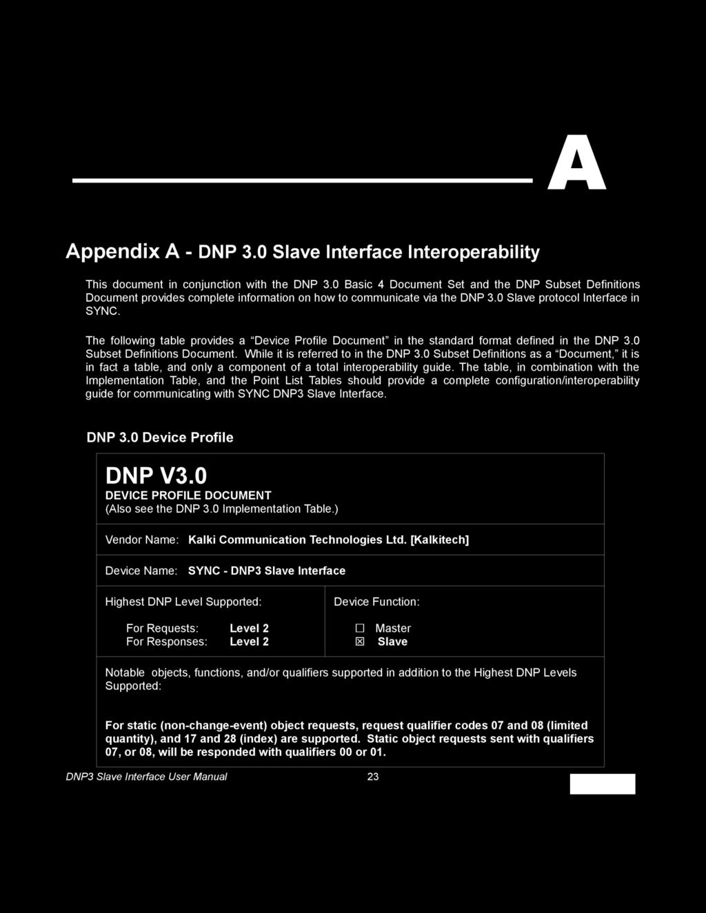
23 23
24 24
25 25
26 26
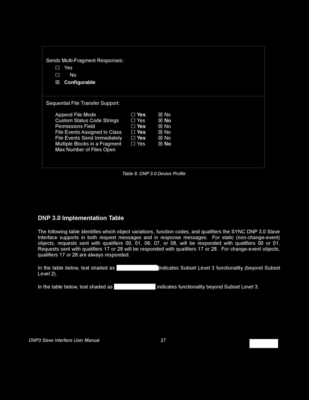
27 27

28 28
29 DNP V3.0 Point List The tables below identify all the data points provided by the implementation. Binary Output Status Points Object Number: 10 Default Variation reported when variation 0 requested: 2 (Binary Output Status) Control Relay Output Blocks Object Number: 12 Point Name/Description Index 0 Float/EQ Mode Indicator (FLOAT=0, EQUALIZE=1) 1 Temperature Compensation Enable (Enabled=1, Not Enabled=0) Binary Input Points Static (Steady-State) Object Number: 1 Static Variation reported when variation 0 requested: 1 (Binary Input 2 without status) Point Index Name/Description 0 AC Fail Alarm Status (OK=0, ALARM=1) 1 Low Voltage Alarm Status (OK=0, ALARM=1) 2 High Voltage Alarm Status (OK=0, ALARM=1) 3 High Voltage Shutdown Alarm Status (OK=0, ALARM=1) 4 Low DC Current Alarm Status (OK=0, ALARM=1) 5 Ground Detection Enable (Enabled=1, Not Enabled=0) Positive Ground Alarm Status (OK=0, ALARM=1) 6 Point will always read 0 when Ground Detection Enabled (Binary Input Point 5) is 0. Negative Ground Alarm Status (OK=0, ALARM=1) 7 Point will always read 0 when Ground Detection Enabled (Binary Input Point 5) is 0. 8 Summary Alarm Status (OK=0, ALARM=1) Blown DC Protection Alarm Status (OK=0, ALARM=1) 9 Point will always read 0 when Ground Detection Enabled (Discrete Input Point 5) is Local Temperature Probe used for Temperature Compensation (INACTIVE=0, ACTIVE=1) 11 Remote Temperature Probe used for Temperature Compensation (INACTIVE=0, ACTIVE=1) 12 Float/EQ Mode Indicator (FLOAT=0, EQUALIZE=1) 13 Temperature Compensation Enable (Enabled=1, Not Enabled=0) 29
30 Analog Inputs Static (Steady-State) Object Number: 30 Static Variation reported when variation 0 requested: 4 (16-Bit Analog Input w/o Flag) Point Index Description, Units 0 Heartbeat. Increments continuously to indicate communications between Controller board and communications board are working. None 1 Board Number. Will read 205 for205ts card. None 2 Software Version, Version of software on 205TS card. None 3 DC Output Voltage, Volts DC Output Current, Amps Equalize Cycle Time Hours Remaining, Hours, Minutes Note: The last two digits are the minutes. None 6 Auto Equalize Timer, Days None 7 Auto Equalize Timer, Hours, Minutes Note: The last two digits are the minutes. None 8 Low DC Current Alarm Low Limit, Amps Note: Settings below this limit disable the Low DC Current Alarm Local Temperature Probe Reading, C None 10 Remote Temperature Probe Reading, C None 11 Equalize Timer Mode (0,1 2,3,4) None 12 Equalize Timer Setting (0 to 144) None 13 Low Voltage Alarm Threshold, Volts High Voltage Alarm Threshold, Volts High Voltage Shutdown Alarm Threshold, Volts Low DC Current Alarm Threshold, Amps Low DC Current Alarm Reset Threshold, Amps 0.1 Scale Factor Analog Outputs Static (Steady-State) Object Number: 40 Static Variation reported when variation 0 requested: 2 (16-Bit Analog Output Status) Point Index Description, Units, Valid Settings/Range 0 Equalize Timer Mode (0,1 2,3,4) None 1 Equalize Timer Setting (0 to 144) None 2 Low Voltage Alarm Threshold, Volts, 0 to High Voltage Alarm Threshold, Volts, 0 to High Voltage Shutdown Alarm Threshold, Volts, 0 to Low DC Current Alarm Threshold, Amps, 0 to Low DC Current Alarm Reset Threshold, Amps, 0 to Scale Factor 30
A12B DNP 3.0 SERIAL & ETHERNET (TCP/IP) SCADA INTERFACE
 SCADA INTERFACE") A12B DNP 3.0 SERIAL & ETHERNET (TCP/IP) SCADA INTERFACE OPTION 21P INSTRUCTIONS This manual is only valid for A12B units equipped with a S2A-225C control module and a S2A-383S-3X20 communications card.
A12B DNP 3.0 SERIAL & ETHERNET (TCP/IP) SCADA INTERFACE OPTION 21P INSTRUCTIONS This manual is only valid for A12B units equipped with a S2A-225C control module and a S2A-383S-3X20 communications card.
DNP 3.0 Serial (RS232/RS485) and Ethernet (TCP/IP) SCADA Interface for A31 Inverters with S2A-383S Option 21P. Setup Instructions
 and Ethernet (TCP/IP) SCADA Interface for A31 Inverters with S2A-383S Option 21P. Setup Instructions") La Marche Manufacturing Company www.lamarchemfg.com DNP 3.0 Serial (RS232/RS485) and Ethernet (TCP/IP) SCADA Interface for A31 Inverters with S2A-383S Option 21P Setup Instructions This manual is valid
La Marche Manufacturing Company www.lamarchemfg.com DNP 3.0 Serial (RS232/RS485) and Ethernet (TCP/IP) SCADA Interface for A31 Inverters with S2A-383S Option 21P Setup Instructions This manual is valid
Setup Instructions. This manual is only valid for A12B Chargers equipped with the following: S2A-225C card with software version P225C0630
 La Marche Manufacturing Company www.lamarchemfg.com DNP 3.0 Serial (RS232/RS485) and Ethernet (TCP/IP) or Fiber SCADA Interface for A12B Chargers Option 21P Option 57T Option 57U Setup Instructions This
A36D/TPSD DNP 3.0 & Modbus SCADA INTERFACE
 SCADA INTERFACE INSTRUCTIONS - OPTION 21P / 21Q - FOR A36D/TPSD SYSTEMS A36D/TPSD DNP 3.0 & Modbus SCADA INTERFACE OPTION 21P / 21Q INSTRUCTIONS This manual is only valid for A36D/TPSD Chargers equipped
DNP 3.0 & Modbus SCADA INTERFACE INSTRUCTIONS FOR 205T BASED SYSTEMS
 DNP 3.0 & Modbus SCADA INTERFACE INSTRUCTIONS - OPTION 21PQ - FOR 205T BASED SYSTEMS DNP 3.0 & Modbus SCADA INTERFACE OPTION 21PQ INSTRUCTIONS FOR 205T BASED SYSTEMS CPN114830 ECN/DATE ISSUE DATE: ECN
A12B / A46 SMNP V3 SCADA INTERFACE INSTRUCTIONS
 A12B / A46 SMNP V3 SCADA INTERFACE OPTION 21X INSTRUCTIONS This manual is only valid for A12B and A46 Chargers equipped with S2A-225C control cards with P225C-0630 software and the S2A-389S communications
Document Name: User Manual for SC10MK, Modbus RTU to Modbus TCP Converter
 Document Name: User Manual for SC10MK, Modbus RTU to Modbus TCP Converter Login for the first time, please use http://192.168.1.100 To key in user name and password is for identifying authorization. Default
ATK3 I/O Module (Modbus Slave)
") ATK3 I/O Module (Modbus Slave) 2011-01-13 The ATK3 I/O Module by ElectroCom Table of contents 2011-01-13...1 The ATK3 I/O Module by ElectroCom...1 1 Hardware...2 1.1 Inputs...3 1.2 Outputs...3 1.2.1 Relay...3
ATK3 I/O Module (Modbus Slave) 2011-01-13 The ATK3 I/O Module by ElectroCom Table of contents 2011-01-13...1 The ATK3 I/O Module by ElectroCom...1 1 Hardware...2 1.1 Inputs...3 1.2 Outputs...3 1.2.1 Relay...3
MB40 & MB45 MODBUS TCP/IP Gateway Handbook
 MB40 & MB45 MODBUS TCP/IP Gateway Handbook Version 1.2 29 July 2014 Environdata Australia Pty Ltd 42-44 Percy Street Warwick Queensland 4370 Australia Phone: (07) 4661 4699 Fax: (07) 4661 2485 International
For more information Contact with details of the application.
 Eaton Corporation Telecommunications Power Solutions Email: dc.info@eaton.com www.eaton.com/telecompower Application Note AN0107 SC200 Modbus Server Last updated 20 January 2017 Applicable products SC200
SCADALink IP100 SCADA Terminal Server QUICK START GUIDE Revision 1.42 June 19, 2012
 SCADA Terminal Server QUICK START GUIDE Revision 1.42 June 19, 2012 www.scadalink.com INTRODUCTION Use this Quick Start Guide to configure a SCADALink IP100. Full documentation is found under the IP100
EVO AT SERIES BATTERY CHARGER AT SERIES BATTERY CHARGER COMMUNICATIONS MANUAL. EVO - Microprocessor Controlled Float Battery Charger JA
 EVO P R O D U C T COMMUNICATIONS MANUAL EVO - Microprocessor Controlled Float Battery Charger JA5011-54 NOTICE! WARNING Table of Contents - ATevo TABLE OF CONTENTS 1. INTRODUCTION.....................................................
ETOR-4. Ethernet/Serial Gateway USER MANUAL
 ETOR-4 Ethernet/Serial Gateway USER MANUAL 1 TABLE OF CONTENTS SECTION 1 GENERAL INFORMATION...6 SECTION 2 INSTALLATION...9 2.1 Definitions on ETOR... 9 2.2 Configuring ETOR...10 2.3 Required Installations
USER S MANUAL. PH232Ex1. #1 RS-232 Serial Port to Ethernet, Terminal Server/Client. Doc No: PH232Ex1-UM-001 IPEX. (IP Electronix)
") USER S MANUAL PH232Ex1 Doc No: PH232Ex1-UM-001 #1 RS-232 Serial Port to Ethernet, Terminal Server/Client IPEX (IP Electronix) Contents 1. INTRODUCTION... 3 2. SPECIFICATIONS... 3 3. PACKAGE CHECKLIST...
USER S MANUAL PH232Ex1 Doc No: PH232Ex1-UM-001 #1 RS-232 Serial Port to Ethernet, Terminal Server/Client IPEX (IP Electronix) Contents 1. INTRODUCTION... 3 2. SPECIFICATIONS... 3 3. PACKAGE CHECKLIST...
DKG-210 UNIVERSAL INTERNET GATEWAY UNIT
 DKG-210 UNIVERSAL INTERNET GATEWAY UNIT AC & DC SUPPLY VERSIONS DESCRIPTION The DKG-210 is designed for internet monitoring and control of industrial devices using different protocols through the RAINBOW
Docking Stations DS-U1, DS-U2, DS-U4, DS-U4-WL and DS-U Adjustment and configuration procedure for the analog inputs
 Page 1 of 17 Docking Stations DS-U1, DS-U2, DS-U4, DS-U4-WL and DS-U4-4-20 Adjustment and configuration procedure for the analog Page 2 of 17 Table of contents 1 Foreword... 3 2 Configuration examples...
Industrial Serial Device Server
 1. Quick Start Guide This quick start guide describes how to install and use the Industrial Serial Device Server. Capable of operating at temperature extremes of -10 C to +60 C, this is the Serial Device
AP-ENBD User Manual V0.2
 AP-ENBD User Manual V0.2 2015/12 Catolog Catolog... 2 1 Introduction... 1 1.1 Communication Structure... 1 1.2 Internal Principle... 2 2 Installation... 2 2.1 Connect to the Same Router (or Switch )...
CONFIGURATION SOFTWARE
 MODBUS GATEWAY CONFIGURATION SOFTWARE MBS100E/G/W MODBUS GATEWAY 01 / 2018 MIKRODEV_SM_MBS100_CG_EN CONTENTS 1 MODBUS GATEWAY CONFIGURATION SOFTWARE... 6 1.1 General Information... 6 1.2 Device Connection...
DATRAN XL4 PLUS RTU Quick Start Guide
 DOC-QSG-XL4-PLUS-RTU DATRAN XL4 PLUS RTU Quick Start Guide Configuring the XL4 Plus RTU The XL4 Plus RTU is configured using software called QTech Workbench. Connection to your PC is via a USB cable (Type
CJ Series EtherNet/IP TM Connection Guide. OMRON Corporation NX-series EtherNet/IP Coupler Unit P656-E1-01
 CJ Series EtherNet/IP TM Connection Guide OMRON Corporation NX-series EtherNet/IP Coupler Unit P656-E1-01 About Intellectual Property Rights and Trademarks Microsoft product screen shots reprinted with
Site Preparation. for AE250 Inverter Installation Guide. SolarVu
 5 Data 6 7 8 9 Site Preparation SolarVu for AE50 Inverter Installation Guide SolarVu is an energy portal that enables remote monitoring of renewable energy generation sites over the web. It requires the
Version 1.0c May 6, 2010 ATK3
 Version 1.0c May 6, 2010 ATK3 Contents 1 Hardware 2 1.1 Inputs............................... 2 1.2 Outputs.............................. 3 1.3 RS485............................... 3 1.4 Ethernet..............................
Industrial 1-port RS422/485 Modbus Gateway IMG-110T
 Industrial 1-port RS422/485 Modbus Gateway IMG-110T Presentation Outlines Product Positioning Applications Product Overview Comparison Product Benefits Appendix Product Features 2 / 43 Product Positioning
DataSite Electronic Flow Meter and Remote Terminal Unit
 DataSite Electronic Flow Meter and Remote Terminal Unit Catalog Numbers 1758-FLO301, 1758-FLO302, 1758- RTU201, 1758-RTU202 Software User Manual FRN 1.30 Important User Information Solid state equipment
Industrial 2-port RS422/485 Modbus Gateway IMG-120T
 Industrial 2-port RS422/485 Modbus Gateway IMG-120T u Product Positioning Presentation Outlines u Applications u Product Overview u Comparison u Product Benefits u Product Features 2 / 42 Product Positioning
ETOR-4 Ethernet/Serial Gateway ETOR-4. Ethernet/Serial Gateway USER MANUAL
 ETOR-4 Ethernet/Serial Gateway USER MANUAL 1 TABLE OF CONTENTS SECTION 1 GENERAL INFORMATION...6 SECTION 2 INSTALLATION...9 2.1 Definitions on ETOR... 9 2.2 Configuring ETOR...10 2.3 Required Installations
INTRINSICALLY SAFE DUPLEXER PROTECTION. ELECTRONICS, INC Vulcan Road Apopka, Florida MOTOR INSTRUCTION MANUAL
 INTRINSICALLY SAFE DUPLEXER INSTRUCTION MANUAL MOTOR PROTECTION ELECTRONICS, INC. 2464 Vulcan Road Apopka, Florida 32703 Phone: Website: (407) 299-3825 www.mpelectronics.com Operating Program Revision:
EGW1-IA3-MB User s Manual
 www.exemys.com Rev. 0 1 Products are in constant evolution to satisfy our customer needs. For that reason, the specifications and capabilities are subject to change without prior notice. Updated information
CAS IKS Gateway (Modbus RTU/TCP and HTML) Manual
 Manual") CAS-2700-42 IKS to Modbus RTU Gateway CAS 2700-42 IKS Gateway (Modbus RTU/TCP and HTML) Manual CAS 2700-42 IKS Gateway Manual Page 1 of 34 BLANK PAGE CAS 2700-42 IKS Gateway Manual Page 2 of 34 Contents
CAS-2700-42 IKS to Modbus RTU Gateway CAS 2700-42 IKS Gateway (Modbus RTU/TCP and HTML) Manual CAS 2700-42 IKS Gateway Manual Page 1 of 34 BLANK PAGE CAS 2700-42 IKS Gateway Manual Page 2 of 34 Contents
Docking Station DS-U4WEB with web server version 1 Instruction Manual
 Page 1 of 15 Docking Station DS-U4WEB with web server version 1 Page 2 of 15 Table of contents 1 Overview... 3 2 Description... 3 2.1 Connector identification... 3 2.2 Probe inputs... 4 2.3 Logical inputs
URC Utility Relay Company
 communications i-comm modbus / rs-485 AC-PRO Communicating Trip Units instruction manual ZERO-Hertz Communicating Trip Units URC Utility Relay Company Chagrin Falls, OH 44023 Phone: 888.289.2864 www.utilityrelay.com
INSTRUCTION MANUAL STATION CONTROLLER SC1000 MOTOR PROTECTION ELECTRONICS, INC.
 INSTRUCTION MANUAL STATION CONTROLLER SC1000 MOTOR PROTECTION ELECTRONICS, INC. 2464 Vulcan Road, Apopka, Florida 32703 Phone: (407) 299-3825 Fax: (407) 294-9435 Revision Date: 9-11-08 Applications: Simplex,
PWR. Power Module Slots
 INSTRUCTION MANUAL ETHERNET INTERFACE MODULE (Modbus/TCP) MODEL BEFORE USE... Thank you for choosing M-System. Before use, please check the contents of the package you received as outlined below. If you
REL 512 Connectivity With A Harris Westronics RTU Using DNP 3.0
 ABB Application Note Substation Automation and Protection Division REL 512 AN-45A-99 REL 512 Connectivity With A Harris Westronics RTU Using DNP 3.0 ABSTRACT: DNP 3.0 is a popular communication protocol
RHF. Railroad High Frequency Battery Charger. Installation and Operation Manual. La Marche Manufacturing Company
 La Marche Manufacturing Company www.lamarchemfg.com RHF Railroad High Frequency Battery Charger Installation and Operation Manual 106 Bradrock Dr. Des Plaines 60018-1967 Tel: 847 299 1188 Fax: 847 299
Innovative Electronics for a Changing World INDEX
 Innovative Electronics for a Changing World INDEX 1. SYSTEM DESCRIPTION 2. BOARD CONNECTIONS terminals and indicators 3. CONNECTION DIAGRAM 4. START UP GUIDE and passwords 5. HOME PAGE 6. STATUS PAGE 7.
Ethernet to RS-232/485 Gateway
 Ethernet to RS-232/485 Gateway (Mode: IP-S) Feature: Operation voltage : DC 7V ~ 20V. RS232 Interface Meets or Exceeds TIA/EIA-232-F and ITU Recommendation V.28 Interface : ±12V levels compatibility. Data
MODBUS TCP/IP TO MODBUS SERIAL GATEWAY. MODEL No: MGate-1024-DC VER 2.0
 MODBUS TCP/IP TO MODBUS SERIAL GATEWAY MODEL No: MGate-1024-DC VER 2.0 MILLENNIUM TECHNOLOGIES 440, MASTER MIND 1, ROYAL PALMS ESTATE AAREY MILK COLONY, GOREGAON (EAST), MUMBAI-400065. INDIA. PH: - 91-22-65229736,
VENTEV INNOVATIONS BTRM200 Battery Test Remote Monitoring System User Guide V1.0. Innovations BTRM200. Battery Test Remote Monitor User Guide
 Innovations BTRM200 Battery Test Remote Monitor User Guide Contact : Ventev Innovations 10999 McCormick Road Hunt Valley, MD 21031 Phone Number 800.759.9996 Email Info@ventev.com 1 Contents 1. 2. 3. 4.
DNP Points List and Implementation
 S&C IntelliCap Plus Automatic Capacitor Control DNP Points List and Implementation Table of Contents Section Page Section Page DNP Points List for IntelliCap Plus Controls...1 Status Points....2 Analog
IntesisBox Modbus Server - BACnet/IP Client
 IntesisBox Modbus Server - BACnet/IP Client Gateway for integration of devices into Modbus (RTU and TCP) systems. Integrate Daikin VRV Air Conditioners into your Modbus system (SCADA, BMS, PLC ). For this,
1. Supplied Items. 2. Connecting the DTS SKT. Input side. Input Side
 This Quick Start Guide is designed to familiarize the user with the connection and configuration of the DTS-SKT and DTS-STKD power meter through RS-485 communication. These instructions are given using
Intech Micro 2300-A8VI analogue input station MODBUS RTU slave application supplementary manual.
 Intech Micro 2300-A8VI analogue input station MODBUS RTU slave application supplementary manual. MODBUS supplementary manual to the 2300-A8VI Installation Guide. The 2300 series stations are designed to
Serial to Ethernet Converter
 Serial to Ethernet Converter User s Manual Version 1.1 2004 Infosystem Technology Corporation Disclaimers The information in this manual has been carefully checked and is believed to be accurate. Infosystem
SENS Setup Utility CONFIGURE CHARGERS/SYSTEMS WITH CUSTOM SETTINGS. Operation Manual
 SENS Setup Utility For SENS MicroGenius and MicroCab TM Products CONFIGURE CHARGERS/SYSTEMS WITH CUSTOM SETTINGS Operation Manual SENS Part Number: 101325 Document Revision: F DCN Number: 107593 Date:
KTA-250 Anemometer Alarm Card
 Connects to Davis Instruments DS7911 Anemometer Monitor both the wind speed and direction Interface to PLCs using the Modbus protocol Communicate via RS232 or 2-wire RS485 Interface to PLCs/Instruments
MODBUS/TCP TO SIEMENS G110/G120/MM440 APPLICATION
 ICP PANEL-TEC MICROBRIDGE INSTALLATION AND OPERATION GUIDE MODBUS/TCP TO SIEMENS G110/G120/MM440 APPLICATION Revision History Revision Date Author Comments 000 02 June 2009 David Walker Initial release.
BTRM200 Battery Test Remote Monitor. User Guide
 BTRM200 Battery Test Remote Monitor User Guide Contact : Ventev Wireless Infrastructure 11126 McCormick Road Hunt Valley, MD 21031 Phone Number 800.851.4965 Email Sales@ventev.com Ventev Wireless Infrastructure
P2 Configuration Guide
 P2 Configuration Guide March 2018 Rev. 4.00 #220, 550 71 st Avenue SE Calgary, Alberta, Canada T2H 0S6 Phone: (403) 255-9544 Fax: (403) 259-2343 www.barnettprotalk.com E-mail: sales@barnettprotalk.com
ELK-IP232 INSTALLATION AND CONFIGURATION MANUAL. Ethernet to Serial Bridge /07
 ELK-IP232 Ethernet to Serial Bridge INSTALLATION AND CONFIGURATION MANUAL http://www.ness.com.au email: support@ness.com.au 1/07 Table of Contents Features and Specifications...3 Basics of Networking...4
USER MANUAL FOR FIOA-0402-U-16
 USER MANUAL FOR FIOA-0402-U-16 COPYRIGHT NOTICE This manual is a publication of Renu Electronics Pvt. Ltd. and is provided for use by its customers only. The contents of the manual are copyrighted by Renu
MGate MB3000 Modbus Gateway User Manual
 MGate MB3000 Modbus Gateway User Manual Sixth Edition, July 2012 www.moxa.com/product 2012 Moxa Inc. All rights reserved. MGate MB3000 Modbus Gateway User s Manual The software described in this manual
NetBiter I/O Extender User Manual
 User Manual Part no. 0920-9999-009 IntelliCom Innovation AB Pilefeltsgatan 73 SE-302 50 Halmstad SWEDEN Phone +46 35 17 29 90 Fax +46 35 17 29 09 email info@intellicom.se www www.intellicom.se Revision
MGate MB3000 Modbus Gateway User s Manual
 User s Manual Seventh Edition, May 2013 www.moxa.com/product 2013 Moxa Inc. All rights reserved. User s Manual The software described in this manual is furnished under a license agreement and may be used
RS-232/422/485 to Copper or Fiber. Ethernet Converter. User s Manual
 RS-232/422/485 to Copper or Fiber Ethernet Converter User s Manual Table Of Contents TABLE OF CONTENTS... 1 INTRODUCTION... 3 PRODUCT OVERVIEW... 3 PRODUCT FEATURES... 3 PACKING LIST... 4 LED INDICATORS...
Ethernet HMi RAC and Gateway Setup Instructions Rev. 09
 Ethernet HMi RAC and Gateway Setup Instructions Rev. 09 Table of Contents Preparing a PXG-900 Gateway...2 Preparing an ELC-CAENET Module... 7 Configuring the HMi RAC... 10 Preparing the ATC-300+... 13
TOP Server V5 to MicroLogix Using DNP3 Ethernet Driver
 TOP Server V5 to MicroLogix 1400 Using DNP3 Ethernet Driver Page 2 of 36 Table of Contents INTRODUCTION 3 CONFIGURING THE MICROLOGIX 1400 AS A DNP3 SLAVE 4 CONFIGURING TOP SERVER AS A DNP3 MASTER 9 TESTING
Contents 1 Warnings, Cautions, and Notes Description Features... 1
 EnCell Contents 1 Warnings, Cautions, and Notes... 1 2 Description... 1 3 Features... 1 3.1 STANDARD FEATURES... 1 3.2 FRONT PANEL FEATURES... 2 3.2.1 Display... 2 3.2.2 OK LED... 2 3.2.3 FAULT LED...
INTEGRATED SYSTEMS AND CONTROL, INC. User s Hardware Manual. PCMNET V 7. xx
 INTEGRATED SYSTEMS AND CONTROL, INC. User s Hardware Manual PCMNET V 7. xx INTEGRATED SYSTEMS AND CONTROLS, INC. PCMNET Users Manual Revised 2/4/2005 2003-2005 Integrated Systems and Control. Inc. PO Box
ACS Stepper _10_Modbus LINEAR SOLUTIONS MADE EASY
 MODBUS RTU & TCP PROGRAMMER S GUIDE ACSI ACS Stepper ACS Servo 3600-4169_10_Modbus LINEAR SOLUTIONS MADE EASY Tolomatic reserves the right to change the design or operation of the equipment described herein
Modbus Server - M-Bus (EN ) Gateway for the integration of M-BUS meters with Modbus RTU and TCP based control systems.
 Gateway for the integration of M-BUS meters with Modbus RTU and TCP based control systems.") IntesisBox Server - M-Bus (EN 13757-3) Gateway for the integration of M-BUS meters with and based control systems. Integrate M-Bus meters into your master device or system (BMS, SCADA, PLC, HMI, TouchPanels
IntesisBox Server - M-Bus (EN 13757-3) Gateway for the integration of M-BUS meters with and based control systems. Integrate M-Bus meters into your master device or system (BMS, SCADA, PLC, HMI, TouchPanels
Installation and Programming Manual. Niobrara Research & Development Corporation P.O. Box 3418 Joplin, MO USA
 DUCM DF1 Manual DUCM DF1 Installation and Programming Manual This manual describes the DUCM application for interfacing DF1 slaves to a Modbus or RNIM serial network. Effective: February 16, 2017 Niobrara
TRP-C37M User s Manual
 TRP-C37M User s Manual MODBUS TCP to RTU/ASCII Gateway Printed May. 2011 Rev 1.1 Trycom Technology Co., Ltd 1F, No.2-11, Sihu street, Yingge Township, Taipei, Taiwan ROC Tel: 886-2-86781191, Fax: 886-2-86781172
MESR9xx. Vlinx Industrial MODBUS Ethernet to Serial Gateway B&B ELECTRONICS PRODUCT INFORMATION
 MESR9xx MESR9xx-1610ds-1/5 Vlinx Industrial MODBUS Ethernet to Serial Gateway Ethernet Enable MODBUS RS-232/422/485 MODBUS TCP, ASCII & RTU Modbus Flexibility Serial & Ethernet, Masters & Slaves Modbus
EnCell Battery Cell Monitor
 EnCell Battery Cell Monitor Instruction Manual Model RCM15S12 NERC Compliant YO R U H T PA TO Z O R E W O D N M I T E enchargepowersystems.com sales@enchargepowersystems.com (888) 407.5040 Contents 1 Warnings,
IntesisBox Modbus Server - Honeywell XLS 80
 IntesisBox Server - Honeywell XLS 80 Gateway for integration of Honeywell XLS 80 fire panels into (RTU and TCP) enabled control systems. Integrate your Honeywell fire panels into your master device or
FNL Modbus TCP Interface
 FNL Modbus TCP Interface Users Manual V0.1 17.06.2009 Project No.: 5304 Doc-ID.: FNL Modbus TCP Interface-UM-V0.1 Status: Released COMSOFT d:\windoc\icp\doku\hw\fnl\modbus tcp\version_0.1\fnl_modbus_tcp_e.doc
Canlan INSTALLATION MANUAL
 Canlan INSTALLATION MANUAL August 2014 Table of Contents Introduction... 4 Overview... 5 RJ45 Connector and Status LEDs... 5 Power Input... 6 RS232 / RS485 Connectors... 7 Installing the Canlan Software...
TRP-C37M User s Manual
 TRP-C37M User s Manual MODBUS TCP to RTU/ASCII Gateway Printed OCT. 2010 Rev 1.0 Trycom Technology Co., Ltd 1F, No.2-11, Sihu street, Yingge Township, Taipei, Taiwan ROC Tel: 886-2-86781191, Fax: 886-2-86781172
Getting Started with your D3000M Series Module
 Getting Started with your D3000M Series Module This document contains step-by-step instructions to quickly connect and communicate with your D3000M modules. The modules require a one-time configuration
isma-b-mg-ip User Manual Global Control 5 Sp. z o.o. Poland, Warsaw
 isma-b-mg-ip User Manual Global Control 5 Sp. z o.o. Poland, Warsaw www.gc5.pl Table of content 1 Introduction... 4 1.1 Revision history... 5 1.2 Safety rules... 5 1.3 Technical specifications... 6 1.4
User Manual A08. User Manual
 A08 TABLE OF CONTENTS TABLE OF CONTENTS... 1 1. INTRODUCTION... 2 1.1. Key Features... 3 1.2. OS Requirement... 4 1.3. Specification... 4 1.4. Packing List... 4 2. OVERVIEW... 5 2.1. LED Definition...
Instruction Manual. Save These Instructions. Centrifugal Compressor Control System. Model Xe-145F Modbus. Instruction Manual
 80446685 Revision B April 2013 Centrifugal Compressor Control System Model Xe-145F Modbus Instruction Manual Instruction Manual Save These Instructions Contents OVERVIEW...................................................................................................
Industrial 1-port RS422/485 Modbus Gateway
 Industrial 1-port RS422/485 Serial Interface One RS422/485 port with 5-contact terminal block Cost effective for RS422/ to Fast Ethernet 10/100BASE- TX application Supports 4-wire RS422 or 2-wire with
SE-330 SERIES (NEW REVISION) MODBUS/TCP INTERFACE
 MODBUS/TCP INTERFACE") Tel: +1-800-832-3873 E-mail: techline@littelfuse.com www.littelfuse.com/se-330 SE-330 SERIES (NEW REVISION) MODBUS/TCP INTERFACE Revision 0-E-121117 Copyright 2018 Littelfuse Startco Ltd. All rights reserved.
Tel: +1-800-832-3873 E-mail: techline@littelfuse.com www.littelfuse.com/se-330 SE-330 SERIES (NEW REVISION) MODBUS/TCP INTERFACE Revision 0-E-121117 Copyright 2018 Littelfuse Startco Ltd. All rights reserved.
DNP3 Communications Protocol
 Powermeter and Power Quality Analyzer PM174 DNP3 Communications Protocol Reference Guide BG0413 Rev. A3 Every effort has been made to ensure that the material herein is complete and accurate. However,
EQ7000. User Manual. Rev 1.00
 EQ7000 User Manual Rev 1.00 www.equustek.com Revision 1.00 February 27, 2009 Contents INTRODUCTION...4 ABOUT THIS MANUAL...4 INTENDED AUDIENCE...4 HARDWARE SPECIFICATIONS...5 PHYSICAL SPECIFICATIONS...5
Voltage regulator TAPCON 240
 Voltage regulator TAPCON 240 Supplement 2398461/01 Protocol description DNP3 All rights reserved by Maschinenfabrik Reinhausen Copying and distribution of this document and utilization and communication
1.1 Remote Annunciator Controller (RAC) and 1 Switch (ATC-600/800) via Modbus TCP/IP Ethernet Gateway (PXG-200/400/600E)
 and 1 Switch (ATC-600/800) via Modbus TCP/IP Ethernet Gateway (PXG-200/400/600E)") Page: 1 of 8 Remote Annunciator Controller (RAC) Instruction Sheet for Automatic Transfer Switches (ATS) Revision:04 IB01602088E 1.1 Remote Annunciator Controller (RAC) and 1 Switch (ATC-600/800) via Modbus
Page: 1 of 8 Remote Annunciator Controller (RAC) Instruction Sheet for Automatic Transfer Switches (ATS) Revision:04 IB01602088E 1.1 Remote Annunciator Controller (RAC) and 1 Switch (ATC-600/800) via Modbus
Product Specification for SAB-S-MODBUS
 SAB-S-MODBUS May 9, 2011 Product Specification for SAB-S-MODBUS The SAB-S-MODBUS is a two-channel module that measures single or multiple magnet transducer position and returns this information to a host
Overview. Table of contents
 1 Table of contents Overview... 1 Applications... 2 Connecting and adjusting of converter... 3 Communication parameters adjusting... 5 RealPort - virtual serial port... 12 Installing virtual serial port
NCOM SERIAL DEVICE SERVER 1XX SERIES USER S MANUAL
 NCOM SERIAL DEVICE SERVER 1XX SERIES USER S MANUAL 2017-07-07 Edition Titan Electronics Inc. Web: www.titan.tw Contents 1. INTRODUCTION... 4 1.1 Key Features... 5 1.2 Specifications... 6 2. PANEL LAYOUT
TCP/IP TO SERIAL (SINGLE PORT) MODEL No: SerEth-1P VER 2.0
 MODEL No: SerEth-1P VER 2.0") TCP/IP TO SERIAL (SINGLE PORT) MODEL No: SerEth-1P VER 2.0 MILLENNIUM TECHNOLOGIES 440, MASTER MIND 1, ROYAL PALMS ESTATE AAREY MILK COLONY, GOREGAON (EAST), MUMBAI-400065. INDIA. PH: - 91-22-65229736,
TCP/IP TO SERIAL (SINGLE PORT) MODEL No: SerEth-1P VER 2.0 MILLENNIUM TECHNOLOGIES 440, MASTER MIND 1, ROYAL PALMS ESTATE AAREY MILK COLONY, GOREGAON (EAST), MUMBAI-400065. INDIA. PH: - 91-22-65229736,
Setting the DCM Switches
 20 The device(s) connected to the DCM will help you determine the appropriate switch settings. Host Computer or Operator Interface Connection If you re using a host computer or operator interface as the
Warranty. Warning. Copyright. Contact Us
 M-6026U-32 16-channel Universal Input and 16-channel Universal Output Version: 1.0.0 Date: Dec. 2017 Edited by Horse Chien M-6026U-32 User Manual Version 1.0.0 Dec. 2017-1 - Warranty All products manufactured
ZLAN5443A. User Manual
 ZLAN5443A Serial Device Server User Manual 4 ports RS232/485/422 To TCP/IP converter CopyRight 2008 Shanghai ZLAN Information Technology Co., Ltd. All right reserved Document DI: ZL DUI 20150413.1.0 1
USER MANUAL FOR GS100/GS1003G
 USER MANUAL FOR GS100/GS1003G 1 Table of Contents 1. INTRODUCTION... 3 2. FEATURES... 3 3. OPERATION... 3 4.CONNECTION DETAILS... 4 5.CONFIGURATION... 5 5.1 Hyper Terminal Setting... 5 5.2 GS100 Configuration...
STM-1 Mux SONET/SDH Multiplexer User Manual
 STM-1 Mux SONET/SDH Multiplexer User Manual [Type the abstract of the document here. The abstract is typically a short summary of the contents of the document. Type the abstract of the document here. The
Advanced Graphical Interface, AGI 100
 APPLICATION NOTES Advanced Graphical Interface, AGI 100 The AGI communication ports Modbus details Specific DEIF driver Example of project creation Document no.: 4189340746A DEIF Screen Designer 1.293
PRODUCT PROFILE & OUTLINE...6
 Warning Please read this instruction carefully before use and follow this instruction to operate the device in order to prevent damages on the device or injuries to staff. Switch off the power before wiring.
Texmate Ethernet Supplement NZ216 Revision
 Revision 20150717 Overview Texmate offers two different Ethernet communication modules. The S8 is an ASCII Ethernet interface centered on a Lantronix XPort Server built into the Ethernet connector. The
IntesisBox Modbus Server KILSEN KSA-7xx. User s Manual 08/2013 r1.2 eng
 IntesisBox Modbus Server KILSEN KSA-7xx User s Manual 08/2013 r1.2 eng Intesis Software S.L. 2013 All rights reserved. Information in this document is subject to change without notice. The software described
Industrial 2-port RS422/485 Modbus Gateway
 2-port RS422/485 Serial Interface Two RS422/485 ports with 5-contact terminal block Cost effective for RS422/ to Fast Ethernet 10/100BASE- TX application Supports 4-wire RS422 or 2-wire with 5-contact
IntesisBox Modbus Server BACnet MSTP and BACnet/IP client
 IntesisBox Modbus Server BACnet MSTP and BACnet/IP client User Manual r1.0 EN Issue date: 04/2018 Intesis Software S.L.U. 2018 All Rights Reserved. Information in this document is subject to change without
UDA2182 Communications User Guide
 UDA2182 Communications User Guide 70-82-25-126 January 2009 Honeywell Process Solutions Copyright, Notices, and Trademarks Printed in U.S.A. Copyright 2008 by Honeywell Revised January 2009 Warranty/Remedy
TECH NOTES-309. Integrating RACO Verbatim Gateway with the Allen-Bradley ControlLogix Series PLC via Ethernet
 TECH NOTES-309 Integrating RACO Verbatim Gateway with the Allen-Bradley ControlLogix Series PLC via Ethernet This technical note explains how to interface the RACO Verbatim Gateway system with the Allen-Bradley
TRP-C37. Ethernet to RS232/422/485 Converter. User s Manual. Printed September Rev 1.6
 TRP-C37 Ethernet to RS232/422/485 Converter User s Manual Printed September 1 2015 Rev 1.6 Trycom Technology Co.,Ltd No.35, Zhongxing Rd., Guishan Township, Taoyuan County 333, Taiwan. Tel : 886-3-350-3351
RS232/RS485/RS422 to TCP/IP Converter ITEM NO.: RS007
 RS232/RS485/RS422 to TCP/IP Converter ITEM NO.: RS007 RS007 is a universal data converter which support serial RS232, RS422 and RS485 to the TCP / IP intelligent communication converter, it offers RS485/RS422
Serial Connection of HC900 Hybrid Controller to 900CS Control Station
 Note: Ethernet connections will provide faster performance than RS-485 HC900 1. Remove HC900 CPU and set S2 Dip Switches for RS-485 unterminated Replace CPU & follow instructions per Installation and User