Setup Instructions. This manual is only valid for A12B Chargers equipped with the following: S2A-225C card with software version P225C0630
|
|
|
- Aldous Dorsey
- 6 years ago
- Views:
Transcription
 and Ethernet (TCP/IP) or Fiber SCADA Interface for A12B Chargers Option 21P Option 57T Option 57U Setup Instructions This manual is only valid for A12B Chargers equipped with")
1 La Marche Manufacturing Company DNP 3.0 Serial (RS232/RS485) and Ethernet (TCP/IP) or Fiber SCADA Interface for A12B Chargers Option 21P Option 57T Option 57U Setup Instructions This manual is only valid for A12B Chargers equipped with the following: S2A-225C card with software version P225C Bradrock Dr. Des Plaines, IL Instruction Drawing Number: P25-LOPT21P57TU-A12B-2 Tel: Fax: CPN Revision A01 Rev. Date: 02/17 ECN: 21378
2 Default Settings The LaMarche Communications Card is shipped with the following default settings: Serial Port Settings Port: RS232 Node Address: 4 Baud Rate: 9600 Data Bits: 8 Stop Bits: 1 Parity: None Ethernet/TCP/Configuration Port Settings Protocol: DNP 3.0 Node Address: 4 IP Address: Subnet: Gateway: TCP Port Number: Ethernet Type: Copper Interface 10/100 Base-T, Fiber Interface 10/100 Base-FX. Configuring the Communications Settings Configuration is accomplished through the front panel. Customers requiring a special configuration they are unable to accomplish through the front panel should contact the factory for assistance. To change the settings use the Menu button to access the menus. From the Settings Menu scroll to the Advanced menu. From the Advanced menu scroll to the Communications menu. Within the Communications menu you may set the following; Remote Disable DNP Node Addr. DNP Serial Port DNP Parity DNP Baud Rate DNP IP Address DNP Subnet Mask DNP Gateway DNP TCP Port Remote Disable This setting when set to YES disables the ability to remotely change all settings making the communications read only. DNP Node Addr. Sets the node address. Use the UP and DOWN arrow buttons to set each digit. Use the LEFT arrow button to move to the next digit in the address. Selections are limited to 0 through DNP Serial Port Sets the serial port to be used. Use the UP and DOWN arrow buttons to select from RS485 and RS232. Note: SW4 on board must be set to match this setting. See figures 1 and 2 below for details. DNP Parity Sets the Parity Type. Use the UP and DOWN arrow buttons to select from NONE, ODD and EVEN. 2
3 DNP Baud Rate Sets the Baud Rate. Use the UP and DOWN arrow buttons to select from 1200, 2400, 4800, 9600, 19200, DNP IP Address Sets the IP Address. Use the UP and DOWN arrow buttons to set each quadrant. Use the LEFT arrow button to move to the next quadrant in the IP Address. NOTE: The following limitations apply to the IP Address setting 1. IP Address should be a proper IP address. 2. IP address should not be Loop back IP address. 3. IP address should not belong to Class D or Class E IP range. 4. IP address should not be network address or broadcast address. 5. IP address and the gateway should be in same subnet. DNP Subnet Mask Sets the Subnet Mask. Use the UP and DOWN arrow buttons to set each quadrant. Use the LEFT arrow button to move to the next quadrant in the IP Address. DNP Gateway Sets the Gateway. Use the UP and DOWN arrow buttons to set each quadrant. Use the LEFT arrow button to move to the next quadrant in the IP Address. NOTE: The following limitations apply to the Gateway setting 1. Gateway may not be set to DNP TCP Port Sets the TCP Port Number. Use the UP and DOWN arrow buttons to set each digit. Use the LEFT arrow button to move to the next digit in the address. Selections are limited to 0 through
 sets the card to either RS232 or RS485. SW3 (red) selects the RS485 biasing and termination resistor configuration.")
4 Communications Board Configuration When using the Serial Ports you must check the 383S card switch settings and make sure switch settings match the DNP Serial Port setting selected in the Communications menu. SW4 (light blue) sets the card to either RS232 or RS485. SW3 (red) selects the RS485 biasing and termination resistor configuration. The silkscreen on the board shows the switch positions for various settings. J2A is the RS232 connection and this port is wired as DTE. TS1 is the RS485 connection. Only one Serial port is active at a time. No configuration is required when using the Ethernet Port. Figure 1 10/100 Base FX Fiber Interface Figure 2 10/100 Base-T Copper Interface 4
5 5
6 6

7 7


8 8


9 9
10 333 10
11 11

12 12
13 13
14 14
15 15


16 16
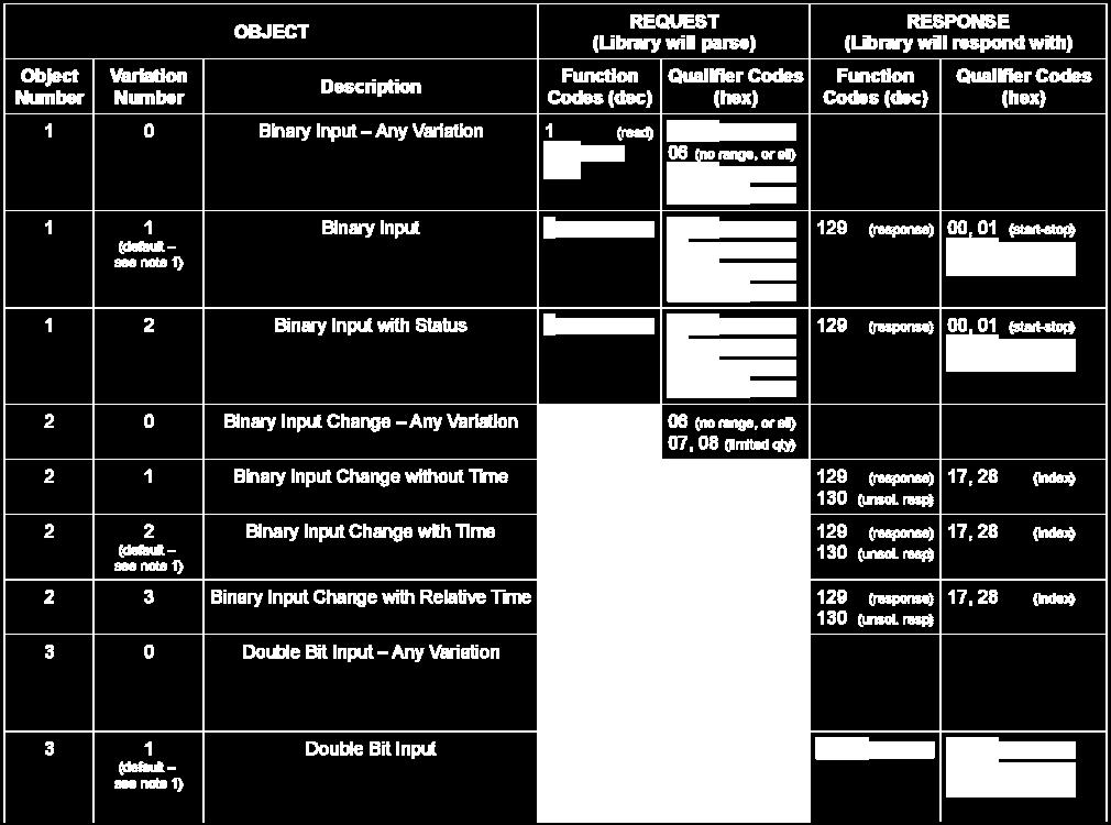
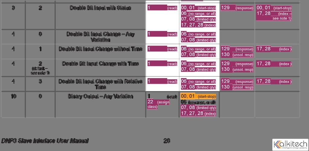
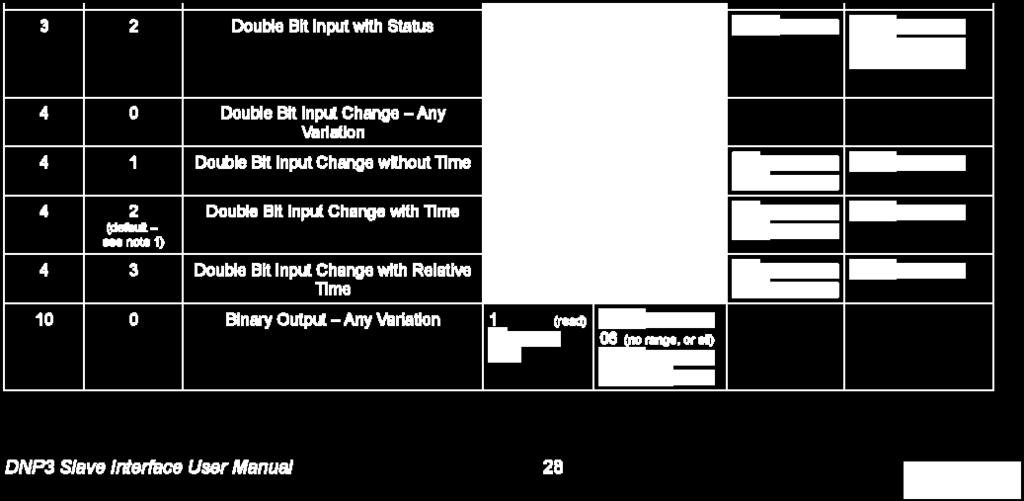
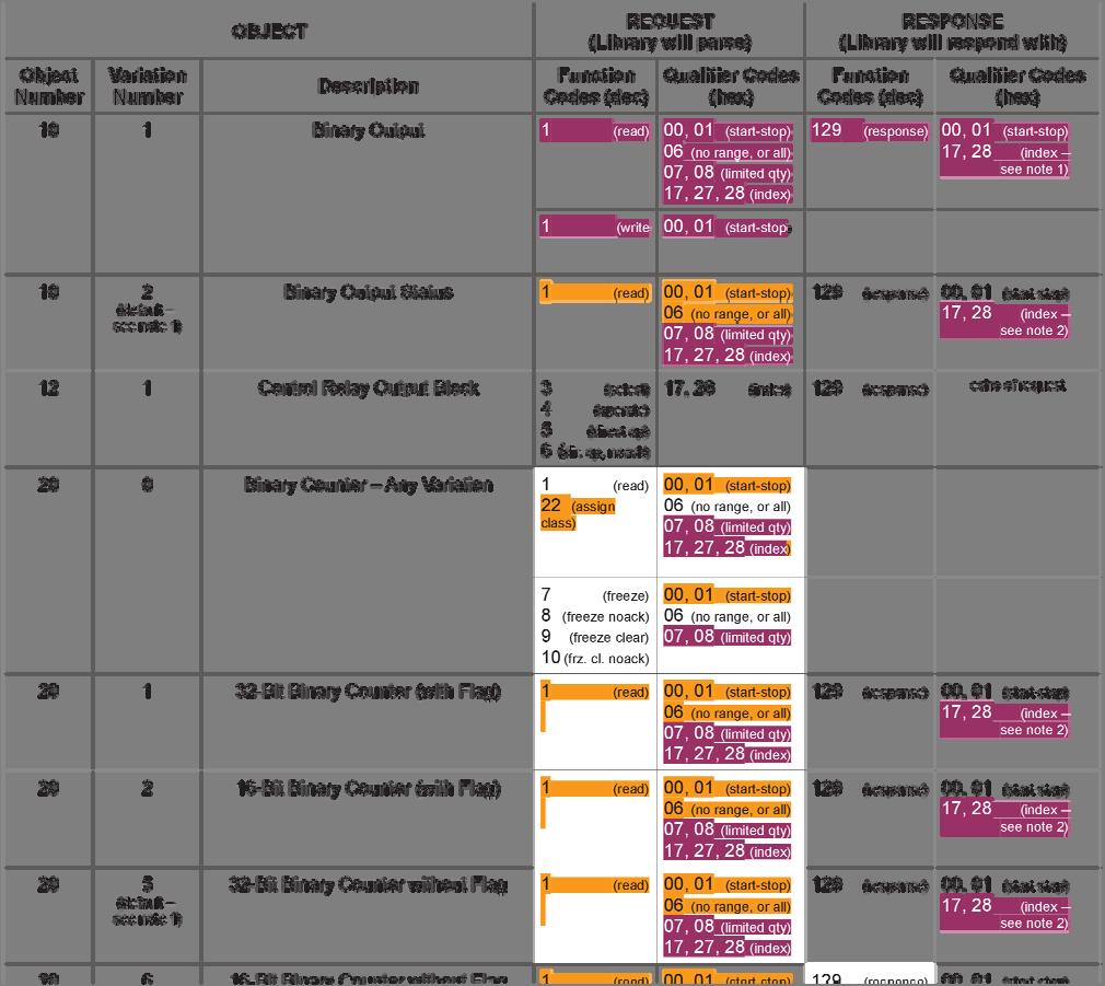
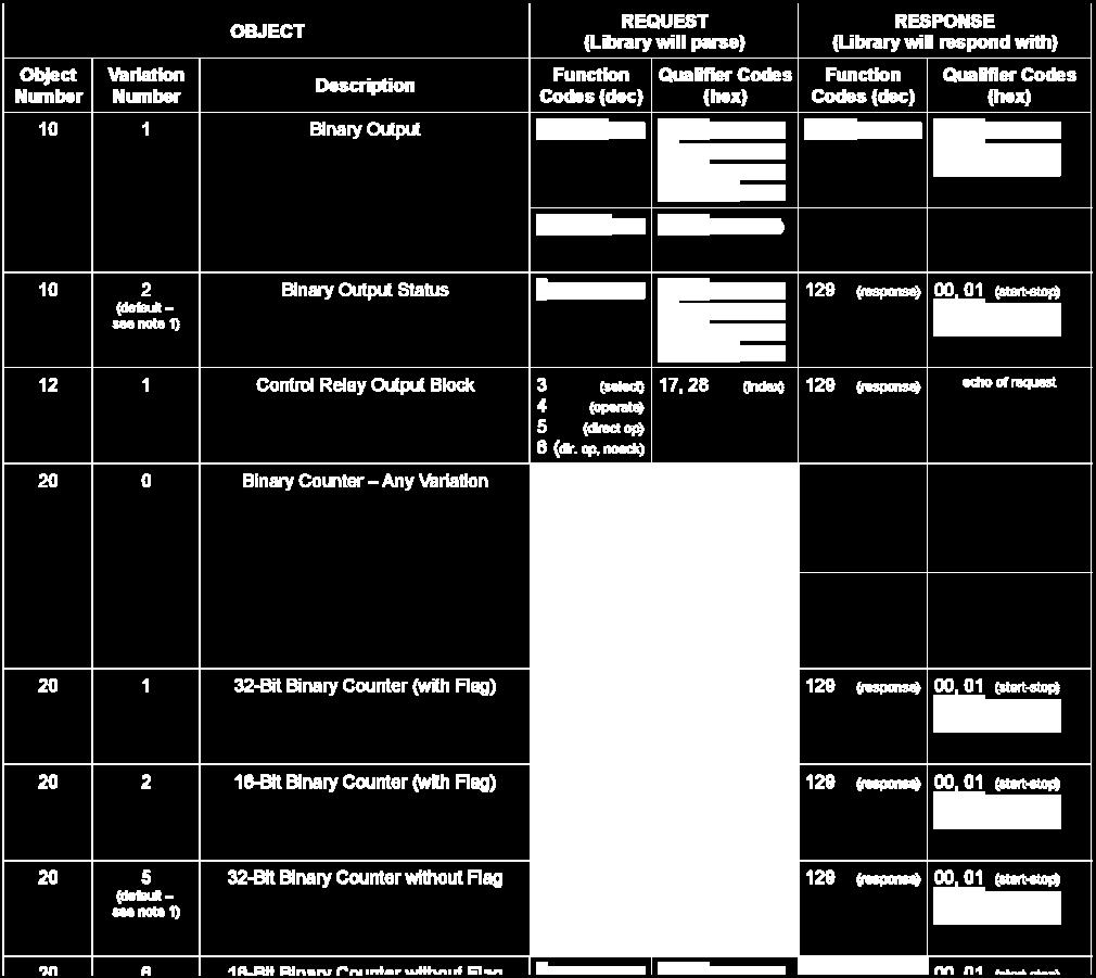
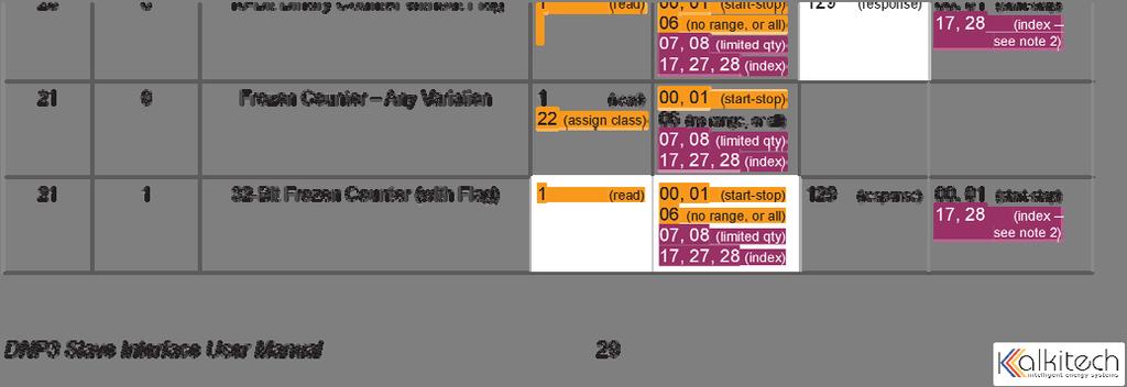
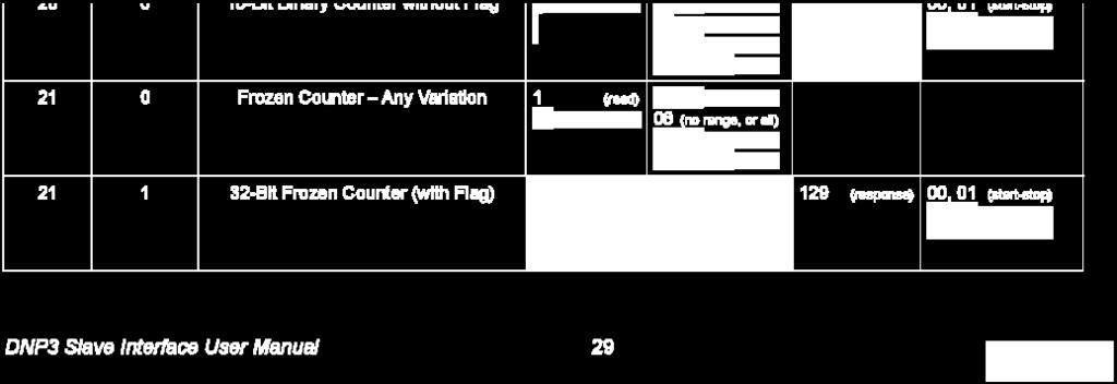
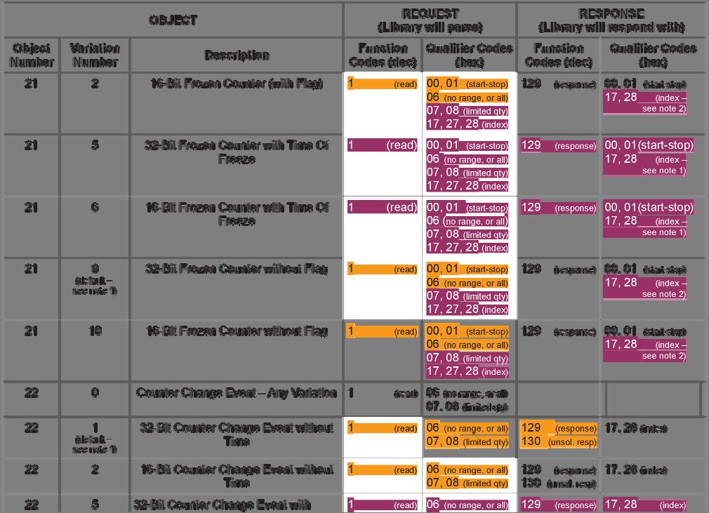
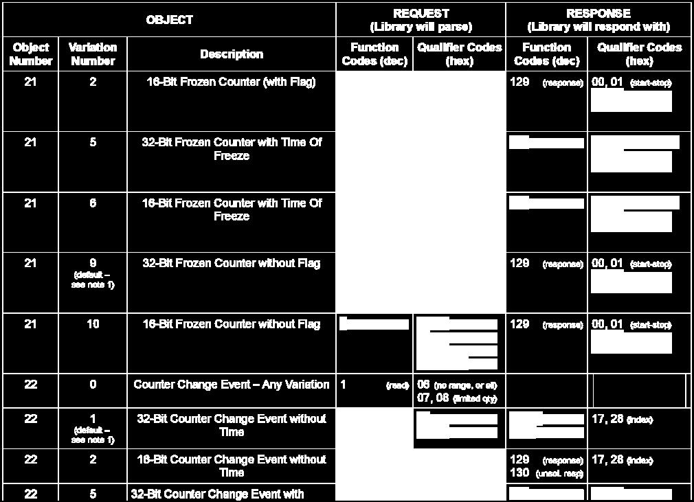
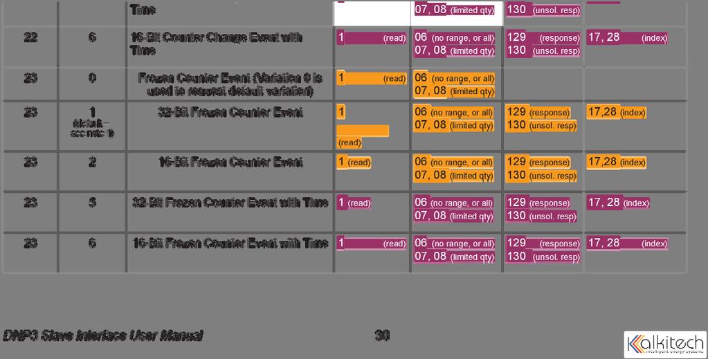
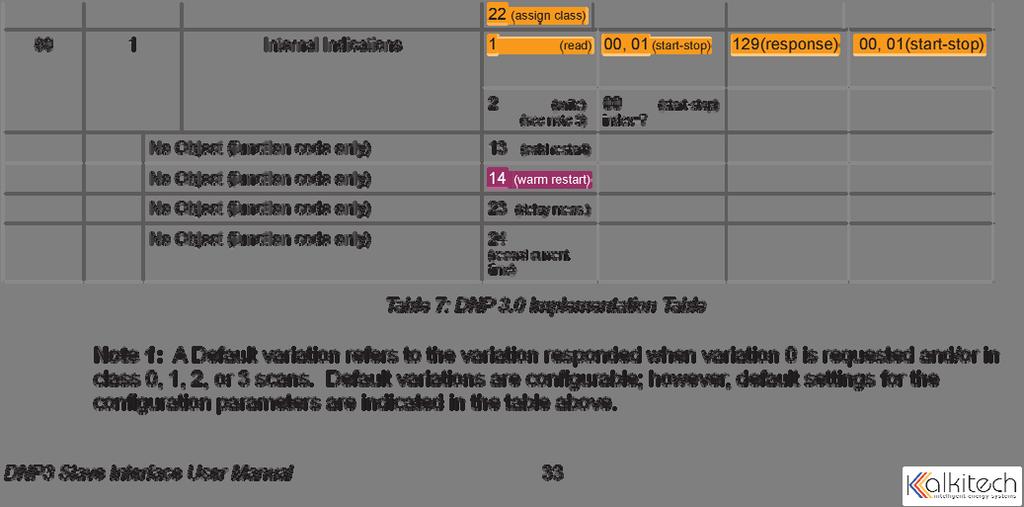
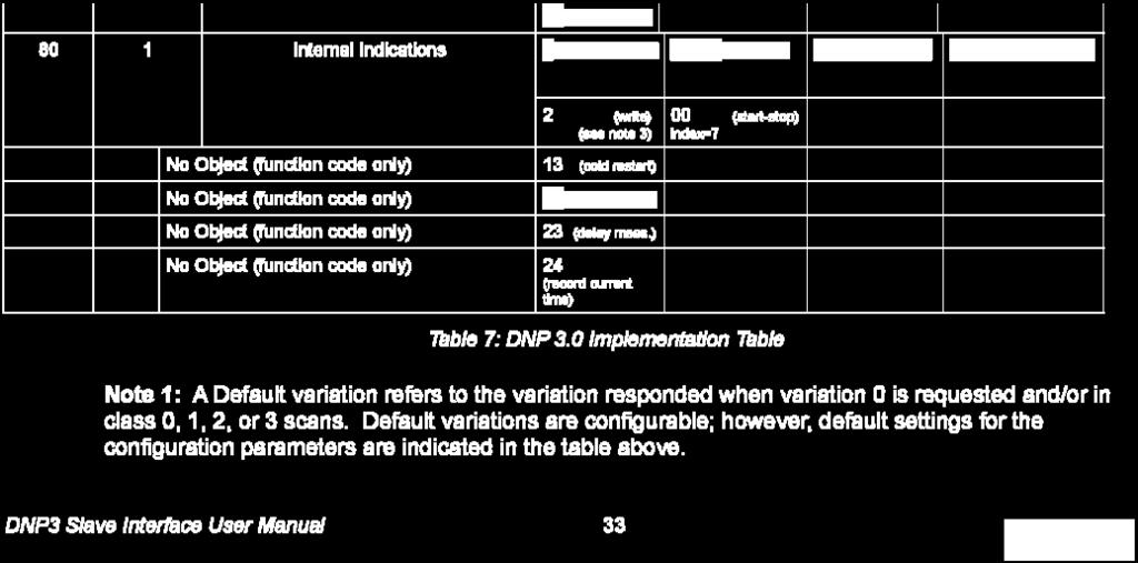
17 DNP V3.0 Point List The tables below identify all the data points provided by the implementation. Binary Input Points Static (Steady-State) Object Number: 1 Static Variation reported when variation 0 requested: 1 (Binary Input 2 without status) Point Name/Description Index 0 AC or Breaker Tripped Indicator (FAILURE=1) 1 High Voltage Alarm Indicator (FAILURE=1) 2 High Voltage Shutdown Alarm Indicator (FAILURE=1) 3 Low Current Alarm Indicator (FAILURE=1) 4 Ground Detection Enabled (ENABLED=1) Positive Ground Alarm Indicator (FAILURE=1). 5 Point will always read 0 when Ground Detection Enabled (Binary Input Point 5) is 0. Negative Ground Alarm Indicator (FAILURE=1). 6 Point will always read 0 when Ground Detection Enabled (Binary Input Point 5) is 0. 7 Summary Alarm Indicator (FAILURE=1) 8 End of Discharge Alarm Indicator (FAILURE=1). 9 Overload Alarm Indicator (FAILURE=1) 10 Charger Failure Alarm Status (FAILURE=1) 11 P60-407S Board Failure Alarm (FAILURE=1) Only applicable to chargers equipped with option. 12 Float/EQ Mode Indicator (FLOAT=0, EQUALIZE=1) Binary Output Status Points Object Number: 10 Default Variation reported when variation 0 requested: 2 (Binary Output Status) Control Relay Output Blocks Object Number: 12 Point Index Name/Description 0 Float/EQ Mode Indicator (FLOAT=0, EQUALIZE=1) 17
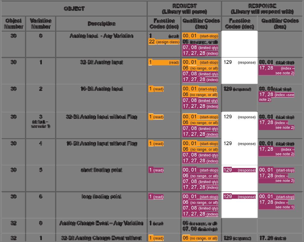
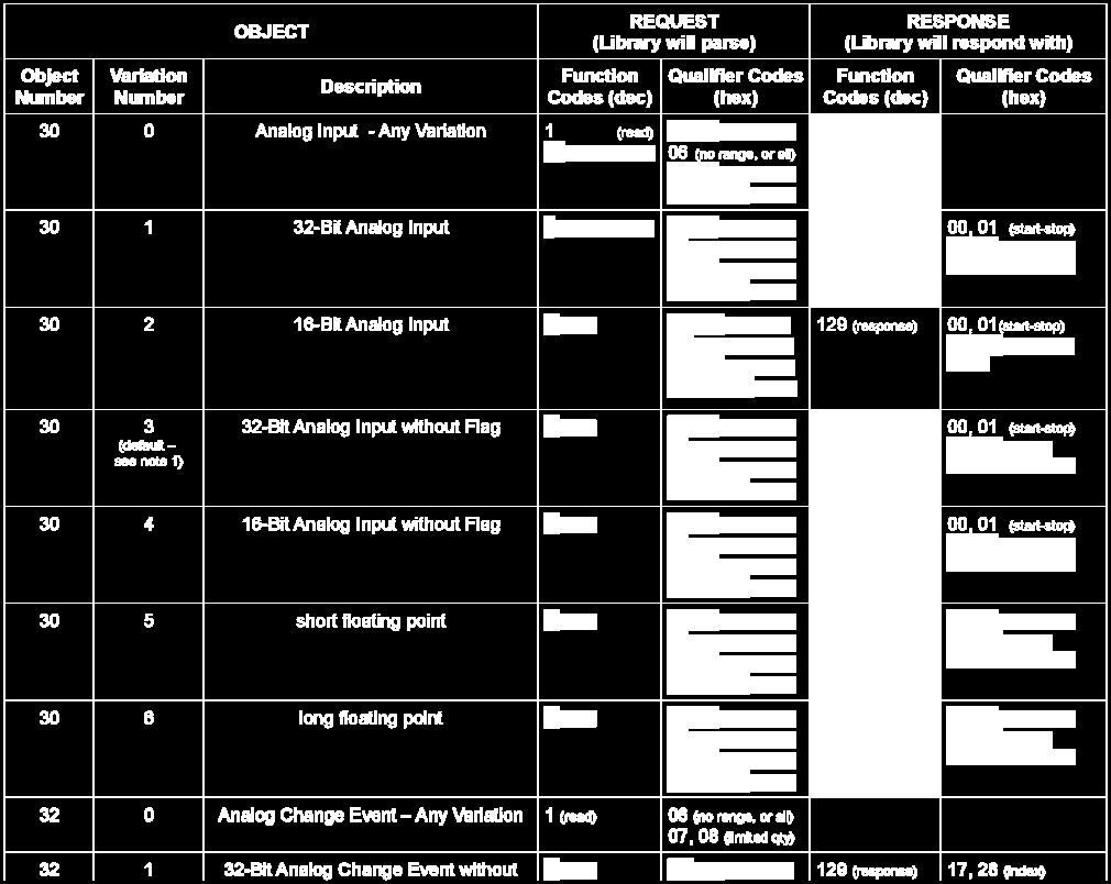
18 Analog Inputs Static (Steady-State) Object Number: 30 Static Variation reported when variation 0 requested: 4 (16-Bit Analog Input w/o Flag) Point Index Description, Units 0 Heartbeat. Increments continuously to indicate communications between Controller board and communications board are working. None 1 Board Number. Will read 368 for 368S card. None 2 Software Version, Version of software on 368S card. None 3 Voltage, Volts Current, Amps Equalize Cycle Time Hours Remaining, Hours, Minutes Note: The last two digits are the minutes. None 6 Auto Equalize Timer, Days None 7 Auto Equalize Timer, Hours, Minutes Note: The last two digits are the minutes. None 8 Low DC Current Alarm Low Limit, Amps. Setting the Low DC Current Alarm below this will result in disabling the Low DC Current Alarm Status 0.1 Indicator. 9 Temperature Probe Reading, Degrees C Note: Reading will always read 0 when charging system is not equipped with a 340S card. A shorted probe will give a reading of 273 and an open None probe will give a reading of Maximum Alarm Voltage, MAXAV, Volts Maximum Alarm Current, MAXAI, Amps Battery Voltage, Volts Note: This is an optional reading and only valid when the charger is 0.1 equipped with the P60-407S board. 13 Low Voltage Alarm Status (0=NO ALARM, 1=LOW VOLTAGE ALARM 2=LOW BATTERY VOLTAGE ALARM None 14 Equalize Timer Mode (0,1 2,3,4) None 15 Equalize Timer Setting (0 to 144) None 16 Low Voltage Alarm Threshold, Volts, (0 to MAXAV) High Voltage Alarm Threshold, Volts, (0 to MAXAV) High Voltage Shutdown Alarm Threshold, Volts, (0 to MAXAV) Low DC Current Alarm Threshold, Amps, (0 to MAXAI) End of Discharge Alarm Threshold, Volts, (0 to MAXAV) Overload Alarm Current, Amps, 0 to MAXI None Scale Factor 18
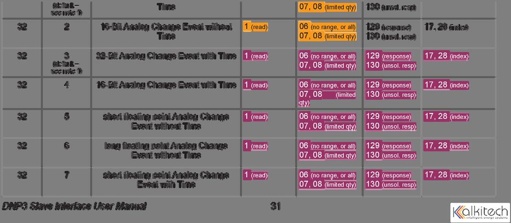
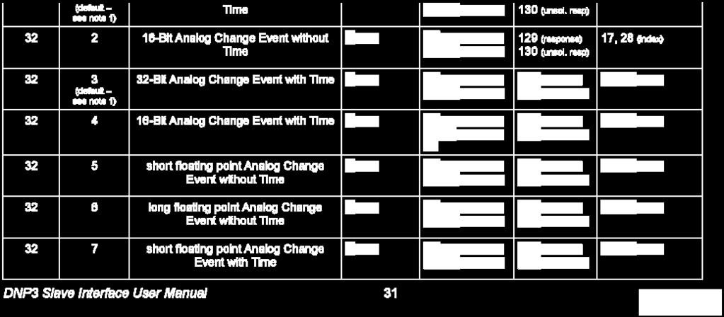
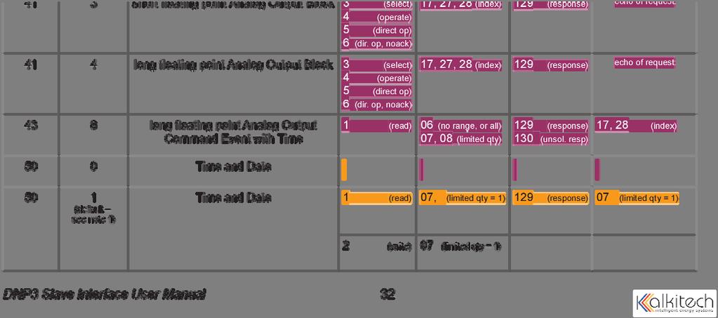
19 Analog Outputs Static (Steady-State) Object Number: 40 Static Variation reported when variation 0 requested: 2 (16-Bit Analog Output Status) Point Index Description, Units, Valid Settings/Range 0 Equalize Timer Mode (0,1 2,3,4) None 1 Equalize Timer Setting (0 to 144) None 2 Low Voltage Alarm Threshold, Volts, (0 to MAXAV) High Voltage Alarm Threshold, Volts, (0 to MAXAV) High Voltage Shutdown Alarm Threshold, Volts, (0 to MAXAV) Low DC Current Alarm Threshold, Amps, (0 to MAXAI) End of Discharge Alarm Threshold, Volts, (0 to MAXAV) Overload Alarm Current, Amps, 0 to MAXI None Scale Factor 19
A12B DNP 3.0 SERIAL & ETHERNET (TCP/IP) SCADA INTERFACE
 SCADA INTERFACE") A12B DNP 3.0 SERIAL & ETHERNET (TCP/IP) SCADA INTERFACE OPTION 21P INSTRUCTIONS This manual is only valid for A12B units equipped with a S2A-225C control module and a S2A-383S-3X20 communications card.
A12B DNP 3.0 SERIAL & ETHERNET (TCP/IP) SCADA INTERFACE OPTION 21P INSTRUCTIONS This manual is only valid for A12B units equipped with a S2A-225C control module and a S2A-383S-3X20 communications card.
DNP 3.0 Serial (RS232/RS485) and Ethernet (TCP/IP) SCADA Interface for TPSD/A36D Chargers with S2A-205T Option 21P or 57T or 57U. Setup Instructions
 and Ethernet (TCP/IP) SCADA Interface for TPSD/A36D Chargers with S2A-205T Option 21P or 57T or 57U. Setup Instructions") La Marche Manufacturing Company www.lamarchemfg.com DNP 3.0 Serial (RS232/RS485) and Ethernet (TCP/IP) SCADA Interface for TPSD/A36D Chargers with S2A-205T Option 21P or 57T or 57U Setup Instructions This
La Marche Manufacturing Company www.lamarchemfg.com DNP 3.0 Serial (RS232/RS485) and Ethernet (TCP/IP) SCADA Interface for TPSD/A36D Chargers with S2A-205T Option 21P or 57T or 57U Setup Instructions This
DNP 3.0 Serial (RS232/RS485) and Ethernet (TCP/IP) SCADA Interface for A31 Inverters with S2A-383S Option 21P. Setup Instructions
 and Ethernet (TCP/IP) SCADA Interface for A31 Inverters with S2A-383S Option 21P. Setup Instructions") La Marche Manufacturing Company www.lamarchemfg.com DNP 3.0 Serial (RS232/RS485) and Ethernet (TCP/IP) SCADA Interface for A31 Inverters with S2A-383S Option 21P Setup Instructions This manual is valid
La Marche Manufacturing Company www.lamarchemfg.com DNP 3.0 Serial (RS232/RS485) and Ethernet (TCP/IP) SCADA Interface for A31 Inverters with S2A-383S Option 21P Setup Instructions This manual is valid
A36D/TPSD DNP 3.0 & Modbus SCADA INTERFACE
 SCADA INTERFACE INSTRUCTIONS - OPTION 21P / 21Q - FOR A36D/TPSD SYSTEMS A36D/TPSD DNP 3.0 & Modbus SCADA INTERFACE OPTION 21P / 21Q INSTRUCTIONS This manual is only valid for A36D/TPSD Chargers equipped
DNP 3.0 & Modbus SCADA INTERFACE INSTRUCTIONS FOR 205T BASED SYSTEMS
 DNP 3.0 & Modbus SCADA INTERFACE INSTRUCTIONS - OPTION 21PQ - FOR 205T BASED SYSTEMS DNP 3.0 & Modbus SCADA INTERFACE OPTION 21PQ INSTRUCTIONS FOR 205T BASED SYSTEMS CPN114830 ECN/DATE ISSUE DATE: ECN
A12B / A46 SMNP V3 SCADA INTERFACE INSTRUCTIONS
 A12B / A46 SMNP V3 SCADA INTERFACE OPTION 21X INSTRUCTIONS This manual is only valid for A12B and A46 Chargers equipped with S2A-225C control cards with P225C-0630 software and the S2A-389S communications
RHF. Railroad High Frequency Battery Charger. Installation and Operation Manual. La Marche Manufacturing Company
 La Marche Manufacturing Company www.lamarchemfg.com RHF Railroad High Frequency Battery Charger Installation and Operation Manual 106 Bradrock Dr. Des Plaines 60018-1967 Tel: 847 299 1188 Fax: 847 299
METERING/DISPLAY MANUAL
 METERING/DISPLAY MANUAL 175W - 750W SINGLE PHASE Series LV EMERGENCY LIGHTING CENTRAL INVERTER Myers Power Products, Inc. 44 South Commerce Way, Bethlehem, PA 18017 1-800-526-5088 (610) 868-3500 Fax: (610)
EVO AT SERIES BATTERY CHARGER AT SERIES BATTERY CHARGER COMMUNICATIONS MANUAL. EVO - Microprocessor Controlled Float Battery Charger JA
 EVO P R O D U C T COMMUNICATIONS MANUAL EVO - Microprocessor Controlled Float Battery Charger JA5011-54 NOTICE! WARNING Table of Contents - ATevo TABLE OF CONTENTS 1. INTRODUCTION.....................................................
CAS SEC (Serial) Protocol for Mitsubishi UPS. Gateway
 Protocol for Mitsubishi UPS. Gateway") CAS-2700-44 SEC (Serial) Protocol for Mitsubishi UPS Modbus (RTU and TCP) and BACnet and HTML Gateway Description The SEC protocol can be used to connect to suitably enabled UPS s manufactured by Mitsubshi.
CAS-2700-44 SEC (Serial) Protocol for Mitsubishi UPS Modbus (RTU and TCP) and BACnet and HTML Gateway Description The SEC protocol can be used to connect to suitably enabled UPS s manufactured by Mitsubshi.
Relay Configuration Form * Required
 Relay Configuration Form * Required 1. Uni directional or Bi directional Relay? Uni directional relays are installed between a source of voltage/current, and a load. Because the primary semiconductors
EnCell Battery Cell Monitor
 EnCell Battery Cell Monitor Instruction Manual Model RCM15S12 NERC Compliant YO R U H T PA TO Z O R E W O D N M I T E enchargepowersystems.com sales@enchargepowersystems.com (888) 407.5040 Contents 1 Warnings,
ATK3 I/O Module (Modbus Slave)
") ATK3 I/O Module (Modbus Slave) 2011-01-13 The ATK3 I/O Module by ElectroCom Table of contents 2011-01-13...1 The ATK3 I/O Module by ElectroCom...1 1 Hardware...2 1.1 Inputs...3 1.2 Outputs...3 1.2.1 Relay...3
ATK3 I/O Module (Modbus Slave) 2011-01-13 The ATK3 I/O Module by ElectroCom Table of contents 2011-01-13...1 The ATK3 I/O Module by ElectroCom...1 1 Hardware...2 1.1 Inputs...3 1.2 Outputs...3 1.2.1 Relay...3
Contents 1 Warnings, Cautions, and Notes Description Features... 1
 EnCell Contents 1 Warnings, Cautions, and Notes... 1 2 Description... 1 3 Features... 1 3.1 STANDARD FEATURES... 1 3.2 FRONT PANEL FEATURES... 2 3.2.1 Display... 2 3.2.2 OK LED... 2 3.2.3 FAULT LED...
Compact Genset Controller, CGC 400 What's in the delivery? The first steps Push-buttons and LEDs
 QUICK START GUIDE Compact Genset Controller, CGC 400 What's in the delivery? The first steps Push-buttons and LEDs DEIF A/S Frisenborgvej 33 DK-7800 Skive Tel.: +45 9614 9614 Fax: +45 9614 9615 info@deif.com
////// SUBSTATIONS. Control command and local Scada
 ////// SUBSTATIONS Control command and local GENERAL INFORMATION The solution provided by Sécheron for local control and monitoring of traction substations is a significant step in supporting operations
isma-b-mg-ip User Manual Global Control 5 Sp. z o.o. Poland, Warsaw
 isma-b-mg-ip User Manual Global Control 5 Sp. z o.o. Poland, Warsaw www.gc5.pl Table of content 1 Introduction... 4 1.1 Revision history... 5 1.2 Safety rules... 5 1.3 Technical specifications... 6 1.4
Owner s Manual Revision 4.01 Option 1
 Owner s Manual Revision 4.01 Option 1 Special Version of the SW series Inverter / Charger for Motor Coach Applications Part # 2031-7 (Supplement to Normal Manual) Effective Date: April 17, 1996 Trace Engineering
Powerware 9315 Hot Sync Parallel Capacity System Bypass Module (SBM)
") Powerware 9315 Hot Sync Parallel Capacity System Bypass Module (SBM) Modbus Profile 164950161 Rev B Read Input Status Modbus Function Code 02 Input registers start at 10000. Register 1 On Battery 0 BOOL
Powerware 9315 Hot Sync Parallel Capacity System Bypass Module (SBM) Modbus Profile 164950161 Rev B Read Input Status Modbus Function Code 02 Input registers start at 10000. Register 1 On Battery 0 BOOL
CAS IKS Gateway (Modbus RTU/TCP and HTML) Manual
 Manual") CAS-2700-42 IKS to Modbus RTU Gateway CAS 2700-42 IKS Gateway (Modbus RTU/TCP and HTML) Manual CAS 2700-42 IKS Gateway Manual Page 1 of 34 BLANK PAGE CAS 2700-42 IKS Gateway Manual Page 2 of 34 Contents
CAS-2700-42 IKS to Modbus RTU Gateway CAS 2700-42 IKS Gateway (Modbus RTU/TCP and HTML) Manual CAS 2700-42 IKS Gateway Manual Page 1 of 34 BLANK PAGE CAS 2700-42 IKS Gateway Manual Page 2 of 34 Contents
Metasys Integrator Powerware Application (previously the Exide Application)
") Application Note Issue Date 11/01/01 APPLICATION NOTE Metasys Integrator Powerware Application (previously the Exide Application) lntroduction Page Application Details Component Requirements 4 Vendor Contact
Application Note Issue Date 11/01/01 APPLICATION NOTE Metasys Integrator Powerware Application (previously the Exide Application) lntroduction Page Application Details Component Requirements 4 Vendor Contact
Industrial Serial Device Server
 1. Quick Start Guide This quick start guide describes how to install and use the Industrial Serial Device Server. Capable of operating at temperature extremes of -10 C to +60 C, this is the Serial Device
THOR Battery Backed DC Power Supply Reference Manual
 THOR Battery Backed DC Power Supply Reference Manual Revision A Firmware Compatibility: V1.03 P/N 60098001 Revised: 4/26/2012 INDUSTRIAL CONTROL LINKS, INC. 12840 Earhart Avenue Auburn, CA 95602 Tel: (800)
SENTRY HPS / HTS COMMUNICATION PROTOCOL
 SENTRY HPS / HTS COMMUNICATION PROTOCOL Rev. 1.00 - October 1996-1 - The communication with Sentry.RPS uses RS232 serial line connection with: - only 3 wires TX, RX and GND; - 8 bits; - no parity; - 1
ISO 9001 CERTIFIED. 607 NW 27th Ave Ocala, FL Phone: (352) or Fax: (352) OPERATION MANUAL. Total System Manager
 or Fax: (352) OPERATION MANUAL. Total System Manager") ISO 9001 CERTIFIED Phone: (352) 629-5020 or 800-533-3569 Fax: (352)-629-2902 Total System Manager PAGE 1 of 17 1. REVISION LOG... 2 2. SYSTEM OVERVIEW... 3 2.1. SCOPE... 3 2.2. FEATURES... 3 3. OPERATIONAL
ISO 9001 CERTIFIED Phone: (352) 629-5020 or 800-533-3569 Fax: (352)-629-2902 Total System Manager PAGE 1 of 17 1. REVISION LOG... 2 2. SYSTEM OVERVIEW... 3 2.1. SCOPE... 3 2.2. FEATURES... 3 3. OPERATIONAL
Communications guide. Line Distance Protection System * F1* GE Digital Energy. Title page
 Title page GE Digital Energy D90 Plus Line Distance Protection System Communications guide D90 Plus firmware revision:.9x GE publication code: 60-9070-F (GEK-3469) GE Digital Energy 650 Markland Street
For more information Contact with details of the application.
 Eaton Corporation Telecommunications Power Solutions Email: dc.info@eaton.com www.eaton.com/telecompower Application Note AN0107 SC200 Modbus Server Last updated 20 January 2017 Applicable products SC200
GE Multilin 350 Feeder Protection Relay Specifications
 GE Multilin 350 Feeder Protection Relay Specifications The feeder protection relay shall provide primary protection of medium voltage distribution feeders. The relay shall be equipped with the following
OPTRIS CT communication interface
 OPTRIS CT communication interface 1. Serial interface parameters Protocol Baud rate: 9600 115200, set by user (factory default: 9600) Data bits: 8 Parity: none Stop bits: 1 Flow control: off The protocol
INTRINSICALLY SAFE DUPLEXER PROTECTION. ELECTRONICS, INC Vulcan Road Apopka, Florida MOTOR INSTRUCTION MANUAL
 INTRINSICALLY SAFE DUPLEXER INSTRUCTION MANUAL MOTOR PROTECTION ELECTRONICS, INC. 2464 Vulcan Road Apopka, Florida 32703 Phone: Website: (407) 299-3825 www.mpelectronics.com Operating Program Revision:
NetBiter I/O Extender User Manual
 User Manual Part no. 0920-9999-009 IntelliCom Innovation AB Pilefeltsgatan 73 SE-302 50 Halmstad SWEDEN Phone +46 35 17 29 90 Fax +46 35 17 29 09 email info@intellicom.se www www.intellicom.se Revision
SENS Setup Utility CONFIGURE CHARGERS/SYSTEMS WITH CUSTOM SETTINGS. Operation Manual
 SENS Setup Utility For SENS MicroGenius and MicroCab TM Products CONFIGURE CHARGERS/SYSTEMS WITH CUSTOM SETTINGS Operation Manual SENS Part Number: 101325 Document Revision: F DCN Number: 107593 Date:
URC Utility Relay Company
 communications i-comm modbus / rs-485 AC-PRO Communicating Trip Units instruction manual ZERO-Hertz Communicating Trip Units URC Utility Relay Company Chagrin Falls, OH 44023 Phone: 888.289.2864 www.utilityrelay.com
Sidewinder Pumps Inc. AC C1D2 Timer/Controller
 Sidewinder Pumps Inc. AC C1D2 Timer/Controller Page 1 of 14 Rev 4/26/17 Table of Contents 1. Warnings --------------------------------------------------------------------------------------------------
Docking Station DS-U4WEB with web server version 1 Instruction Manual
 Page 1 of 15 Docking Station DS-U4WEB with web server version 1 Page 2 of 15 Table of contents 1 Overview... 3 2 Description... 3 2.1 Connector identification... 3 2.2 Probe inputs... 4 2.3 Logical inputs
Doc October ProtoNode Reference Manual
 Doc. 66932-001 October 2015 ProtoNode Reference Manual ii ProtoNode Reference Manual 66932-001 Table of Contents 1.0 INTRODUCTION... 1 2.0 PACKAGE COMPONENTS (CHECK-LIST)... 1 3.0 PRODUCT DESCRIPTION...
Innovative Electronics for a Changing World INDEX
 Innovative Electronics for a Changing World INDEX 1. SYSTEM DESCRIPTION 2. BOARD CONNECTIONS terminals and indicators 3. CONNECTION DIAGRAM 4. START UP GUIDE and passwords 5. HOME PAGE 6. STATUS PAGE 7.
CRAGG RAILCHARGER Instruction Manual for 10DTC-12V 20DTC-12V 30DTC-24V 40DTC-12V 60DTC-12V
 CRAGG RAILCHARGER for 10DTC-12V 20DTC-12V 30DTC-24V 40DTC-12V 60DTC-12V Contents 1 Warnings, Cautions, and Notes... 1 2 Description... 2 3 Features... 2 3.1 STANDARD FEATURES... 2 3.2 CHARGER REGULATION...
BTRM200 Battery Test Remote Monitor. User Guide
 BTRM200 Battery Test Remote Monitor User Guide Contact : Ventev Wireless Infrastructure 11126 McCormick Road Hunt Valley, MD 21031 Phone Number 800.851.4965 Email Sales@ventev.com Ventev Wireless Infrastructure
Multi-instrument Communication, MIC-2 MKII DIN Quick Start Guide
 Multi-instrument Communication, MIC-2 MKII DIN Quick Start Guide Warnings and legal information Installation and terminals Communication I/O options Alarming Utility software More information Specifications
RS-232/422/485 to Copper or Fiber. Ethernet Converter. User s Manual
 RS-232/422/485 to Copper or Fiber Ethernet Converter User s Manual Table Of Contents TABLE OF CONTENTS... 1 INTRODUCTION... 3 PRODUCT OVERVIEW... 3 PRODUCT FEATURES... 3 PACKING LIST... 4 LED INDICATORS...
PSC-10A Programmable Smart Charger. User's Guide
 PSC-10A Programmable Smart Charger User's Guide 990 South Rogers Circle, Suite 11 Boca Raton, FL 33487 Tel: 561-997-2299 Fax: 561-997-5588 www.alber.com Safety Information Except as explained in this manual,
Intelligent Devices IDI 1100 Series Technical Manual
 Intelligent Devices IDI 1100 Series 4411 Suwanee Dam Road, Suite 510 Suwanee, GA 30024 T: (770) 831-3370 support@intelligentdevicesinc.com Copyright 2011, Intelligent Devices, Inc. All Rights Reserved
Ethernet to Serial Port Module RS-232/422/485 to Internet Gateway
 Ethernet to Serial Port Module RS-232/422/485 to Internet Gateway (Model: IPM-S) Wireless Gateway: Active RFID Gateway Bluetooth to Internet Application: Energy Meter Networks Motor Control Industrial
Modbus Register Map: Galaxy 300
 Modbus Map: Galaxy 300 Notes: 1. 16-bit are transmitted MSB first (i.e. big-endian). 2. INT32 UINT16 and and UINT32 are are most-significant word in in n+0, least significant word in in n+1 n+1 (i.e. (i.e.
MODBUS TCP/IP TO MODBUS SERIAL GATEWAY. MODEL No: MGate-1024-DC VER 2.0
 MODBUS TCP/IP TO MODBUS SERIAL GATEWAY MODEL No: MGate-1024-DC VER 2.0 MILLENNIUM TECHNOLOGIES 440, MASTER MIND 1, ROYAL PALMS ESTATE AAREY MILK COLONY, GOREGAON (EAST), MUMBAI-400065. INDIA. PH: - 91-22-65229736,
PS-4100 POWER SUPPLY MANUAL
 PS-4100 POWER SUPPLY MANUAL Manual Part Number 180-0573 December 7, 2006 TABLE OF CONTENTS TITLE PAGE Table of Contents... 2 List Of Figures... 3 1. Introduction... 4 1.0. General... 4 1.1. Features...
D115 The Fast Optimal Servo Amplifier For Brush, Brushless, Voice Coil Servo Motors
 D115 The Fast Optimal Servo Amplifier For Brush, Brushless, Voice Coil Servo Motors Ron Boe 5/15/2014 This user guide details the servo drives capabilities and physical interfaces. Users will be able to
VENTEV INNOVATIONS BTRM200 Battery Test Remote Monitoring System User Guide V1.0. Innovations BTRM200. Battery Test Remote Monitor User Guide
 Innovations BTRM200 Battery Test Remote Monitor User Guide Contact : Ventev Innovations 10999 McCormick Road Hunt Valley, MD 21031 Phone Number 800.759.9996 Email Info@ventev.com 1 Contents 1. 2. 3. 4.
ELK-IP232 INSTALLATION AND CONFIGURATION MANUAL. Ethernet to Serial Bridge /07
 ELK-IP232 Ethernet to Serial Bridge INSTALLATION AND CONFIGURATION MANUAL http://www.ness.com.au email: support@ness.com.au 1/07 Table of Contents Features and Specifications...3 Basics of Networking...4
Distribution Substations Relaying
 Distribution Substations Relaying Trends That Will Affect Your Next Design Court H. Weathers, PE August 2018 1 Trend: Increasing Integration 3 ElectromechanincalRelays & RTUs Limited Status (52a) Few Controls
EtherSeries. EtherSeries CR-2. CR-2-Opto. User s Guide. Revised October 7, 2013 Firmware Version 1.X
 EtherSeries EtherSeries CR-2 & CR-2-Opto User s Guide Revised October 7, 2013 Firmware Version 1.X TABLE OF CONTENTS SECTION 1 - DESCRIPTION... 2 SECTION 2 - SPECIFICATIONS... 4 SECTION 3 - INSTALLATION...
QUICK START GUIDE Paralleling and Protection Unit PPU 300
 QUICK START GUIDE Paralleling and Protection Unit PPU 300 DEIF A/S Frisenborgvej 33 DK-7800 Skive Tel.: +45 9614 9614 Fax: +45 9614 9615 info@deif.com www.deif.com Document no.: 4189341107B 1. Introduction
MONITORING AND CONTROL REQUIREMENTS FOR DISTRIBUTED GENERATION FACILITIES
 MONITORING AND CONTROL REQUIREMENTS FOR DISTRIBUTED GENERATION FACILITIES 1. Introduction Real time monitoring and control is necessary to ensure public and employee safety and to protect the integrity
RS232/RS485/RS422 to TCP/IP Converter ITEM NO.: RS007
 RS232/RS485/RS422 to TCP/IP Converter ITEM NO.: RS007 RS007 is a universal data converter which support serial RS232, RS422 and RS485 to the TCP / IP intelligent communication converter, it offers RS485/RS422
DNP Points List and Implementation
 S&C IntelliCap Plus Automatic Capacitor Control DNP Points List and Implementation Table of Contents Section Page Section Page DNP Points List for IntelliCap Plus Controls...1 Status Points....2 Analog
Model (DRS-54V) Ver. 2.0 August. Dongah Rectifier System Operating Manual
 Ver. 2.0 August. Dongah Rectifier System Operating Manual") 2011 Model (DRS-54V) Ver. 2.0 August DRS-54V Dongah Rectifier System AC 240V 1Phase 3WIRE Input -54VDC Output 55A per Shelf 18.5Amps per Module DONGAHELECOMM.LTD _ Proprietary This document contains proprietary
2011 Model (DRS-54V) Ver. 2.0 August DRS-54V Dongah Rectifier System AC 240V 1Phase 3WIRE Input -54VDC Output 55A per Shelf 18.5Amps per Module DONGAHELECOMM.LTD _ Proprietary This document contains proprietary
Wiring Guide EP.HIO. Version 1.03 Last Updated:
 Wiring Guide EP.HIO Version 1.03 Last Updated: 14-10-2014 1 Note: See http://www.entrypass.net/ for updates, revisions, and download the latest installation manual Platform1 version 3 support 6 and 10
Multi-instrument Communication, MIC-2 MKII DIN Quick Start Guide
 Multi-instrument Communication, MIC-2 MKII DIN Quick Start Guide Warnings and legal information Installation and terminals Communication I/O options Alarming Utility software More information Specifications
Pack Manager Program System Design Document
 PACK MANAGER PROGRAM SYSTEM DESIGN DOCUMENT 1 Pack Manager Program System Design Document Latest Revision: 26 March 2014 Prepared by: Naing Htet Abstract This document describes the design of the software
INSTRUCTION MANUAL A START-UP AND SHUT DOWN LOAD SEQUENCER AND AUTOMATIC LOAD SHEDDING SYSTEM WITH INTEGRAL RELAYS FOR 8 LOADS MODEL #091-60A
 FILE: 09-60A.PMD DATE: 07-30-09 REV. B INSTRUCTI MANUAL LOAD MANAGER MARK II A START-UP AND SHUT DOWN LOAD SEQUENCER AND AUTOMATIC LOAD SHEDDING SYSTEM WITH INTEGRAL RELAYS FOR 8 LOADS MODEL #09-60A INPUT:
TCP/IP TO SERIAL (SINGLE PORT) MODEL No: SerEth-1P VER 2.0
 MODEL No: SerEth-1P VER 2.0") TCP/IP TO SERIAL (SINGLE PORT) MODEL No: SerEth-1P VER 2.0 MILLENNIUM TECHNOLOGIES 440, MASTER MIND 1, ROYAL PALMS ESTATE AAREY MILK COLONY, GOREGAON (EAST), MUMBAI-400065. INDIA. PH: - 91-22-65229736,
TCP/IP TO SERIAL (SINGLE PORT) MODEL No: SerEth-1P VER 2.0 MILLENNIUM TECHNOLOGIES 440, MASTER MIND 1, ROYAL PALMS ESTATE AAREY MILK COLONY, GOREGAON (EAST), MUMBAI-400065. INDIA. PH: - 91-22-65229736,
MB40 & MB45 MODBUS TCP/IP Gateway Handbook
 MB40 & MB45 MODBUS TCP/IP Gateway Handbook Version 1.2 29 July 2014 Environdata Australia Pty Ltd 42-44 Percy Street Warwick Queensland 4370 Australia Phone: (07) 4661 4699 Fax: (07) 4661 2485 International
750/760 COMMUNICATIONS GUIDE. Digital Energy Multilin. Feeder Management Relay
 Digital Energy Multilin 750/760 Feeder Management Relay COMMUNICATIONS GUIDE Software Revision: 7.3x GE Multilin Part Number: 1601-0229-A7 GE Publication Code: GEK-106473F Copyright 2010 GE Multilin GE
Voltage regulator TAPCON 240
 Voltage regulator TAPCON 240 Supplement 2398461/01 Protocol description DNP3 All rights reserved by Maschinenfabrik Reinhausen Copying and distribution of this document and utilization and communication
DGSZV-EP DIGITAL GALVANIC LONGITUDINAL DIFFERENTIAL PROTECTION. Application field
 DGSZV-EP DIGITAL GALVANIC LONGITUDINAL DIFFERENTIAL PROTECTION The digital galvanic longitudinal differential protection of type DGSZV-EP is part of device family named EuroProt. This short description
QUICK START GUIDE Generator Protection Unit GPU 300
 QUICK START GUIDE Generator Protection Unit GPU 300 DEIF A/S Frisenborgvej 33 DK-7800 Skive Tel.: +45 9614 9614 Fax: +45 9614 9615 Info@deif.com www.deif.com Document no.: 4189341035A 1. Introduction 1.1
HAT600 Series HAT600/HAT600I/HAT600B/HAT600BI ATS CONTROLLER USER MANUAL
 HAT600 Series HAT600/HAT600I/HAT600B/HAT600BI ATS CONTROLLER USER MANUAL ZHENGZHOU SMARTGEN TECHNOLOGY CO.,LTD CONTENT 1 OVERVIEW... 5 2 PERFORMANCE AND CHARACTERISTICS... 6 3 SPECIFICATION... 8 4 OPERATING...
Substation Automation Products. High impedance differential busbar protection REB650 Relion 650 series
 Substation Automation Products High impedance differential busbar protection REB650 Relion 650 series One IED for a wide range of high impedance differential protection applications ABB introduces a new,
E2 Modbus RTU Register Map Revision History Version Comments Author Date 1.02 Previous version PAE 11/06/ Revised to new format PAE 09/03/09
 Application Note Title AN-ODE-01 E2 Modbus RTU Register Map Revision History Version Comments Author Date 1.02 Previous version PAE 11/06/08 1.03 Revised to new format PAE 09/03/09 General This document
5 to100 Amperes Linear Power Supply/Charger (120 Volt 60Hz) (220 Volt 50Hz)
 (220 Volt 50Hz)") 5 to100 Amperes Linear Power Supply/Charger (120 Volt 60Hz) (220 Volt 50Hz) Products Options 120 volt 60Hz AC input, 54 volt 5 to 100 Amp output Linear Charger: 220/240 volt 50/60Hz AC input, 54 volt 5
5 to100 Amperes Linear Power Supply/Charger (120 Volt 60Hz) (220 Volt 50Hz) Products Options 120 volt 60Hz AC input, 54 volt 5 to 100 Amp output Linear Charger: 220/240 volt 50/60Hz AC input, 54 volt 5
GE Infrastructure Sensing
 GE Infrastructure Sensing 913-299A January 2005 MODBUS Communications for the GC868 Introduction Your Model GC868 hardware and software (GC3E.MBS) have been modified to provide improved MODBUS communications.
Voltage regulator TAPCON 260
 Voltage regulator TAPCON 260 Supplement 2531994/01 Protocol description MODBUS All rights reserved by Maschinenfabrik Reinhausen Copying and distribution of this document and utilization and communication
POWER Shiloh Road Alpharetta, Georgia (770) FAX (770) Toll Free
 FAX (770) Toll Free") Instruction Manual Model 1582-10M Protection Switch January 2009 Rev O ALARMS MENU OUTPUT = CH1 AUTO POWER 1 2 MODEL 1582 SWITCH CROSS TECHNOLOGIES INC. CH1 CH2 REMOTE EXECUTE Data, drawings, and other
Instruction Manual Model 1582-10M Protection Switch January 2009 Rev O ALARMS MENU OUTPUT = CH1 AUTO POWER 1 2 MODEL 1582 SWITCH CROSS TECHNOLOGIES INC. CH1 CH2 REMOTE EXECUTE Data, drawings, and other
User Manual A08. User Manual
 A08 TABLE OF CONTENTS TABLE OF CONTENTS... 1 1. INTRODUCTION... 2 1.1. Key Features... 3 1.2. OS Requirement... 4 1.3. Specification... 4 1.4. Packing List... 4 2. OVERVIEW... 5 2.1. LED Definition...
ZLAN5443A. User Manual
 ZLAN5443A Serial Device Server User Manual 4 ports RS232/485/422 To TCP/IP converter CopyRight 2008 Shanghai ZLAN Information Technology Co., Ltd. All right reserved Document DI: ZL DUI 20150413.1.0 1
9120 Redundant Probe System (RPSC)
") 9120 Redundant Probe System (RPSC) USER S MANUAL Super Systems Inc. 7205 Edington Drive Cincinnati, OH 45249 Ph : 513-772-0060, 800-666-4330 Fax: 513-772-9466 www.supersystems.com Super Systems Inc. help
9120 Redundant Probe System (RPSC) USER S MANUAL Super Systems Inc. 7205 Edington Drive Cincinnati, OH 45249 Ph : 513-772-0060, 800-666-4330 Fax: 513-772-9466 www.supersystems.com Super Systems Inc. help
8 Button IP Controller Installation and Operation Manual AV-IP-C8-WH
 8 Button IP Controller Installation and Operation Manual AV-IP-C8-WH West Penn Wire 2018 94-000880-A / SE-000880-A Page 1 / 20 Introduction The 8 Button IP Controller (Model: AV-IP-C8-WH) is a versatile
UDA2182 Communications User Guide
 UDA2182 Communications User Guide 70-82-25-126 January 2009 Honeywell Process Solutions Copyright, Notices, and Trademarks Printed in U.S.A. Copyright 2008 by Honeywell Revised January 2009 Warranty/Remedy
Serial to Ethernet Converter
 Serial to Ethernet Converter User s Manual Version 1.1 2004 Infosystem Technology Corporation Disclaimers The information in this manual has been carefully checked and is believed to be accurate. Infosystem
DECK All-In-One Enclosure. Quick Installation Guide for Field Installers
 DECK All-In-One Enclosure Quick Installation Guide for Field Installers 1 Contents Legal Statement... 2 Preliminary Considerations... 2 Required Installation Tools and Materials... 2 Networking Information...
RS485 MODBUS Module 6RO
 Version 2.0 12/02/2013 Manufactured for Thank you for choosing our product. This manual will help you with proper support and proper operation of the device. The information contained in this manual have
EPGG001. Fieldbus Gateway RS-232 to PROFINET. Industrial Communication. Technical Data. Part Number
 Fieldbus Gateway RS-232 to PROFINET EPGG001 Part Number Easy handling Gateway from RS-232/422/485 interfaces to PROFINET With two Industrial Ethernet ports Technical Data Electrical Data Supply Voltage
Weighing technology. FAQs SIWAREX WP231. How can a WIPOTEC digital load cell be used with WP231? V1.0 July Siemens.
 Weighing technology FAQs SIWAREX WP231 How can a WIPOTEC digital load cell be used with WP231? V1.0 July 2016 Siemens.com/weighing 1. Table of contents General...2 2. Hardware requirements...2 3. Software
Opal Pro AB Ethernet IP. Opal Pro MS6 SERIES. AB Ethernet IP Interface Users Manual. Revision Page 1
 Opal Pro MS6 SERIES AB Ethernet IP Interface Users Manual Revision 1.02 Page 1 Page 2 FOR YOUR SAFETY Only qualified personnel should install this equipment, after first reading and understanding all the
INDEX. Network Power Monitor R10 SNMP
 Innovative Electronics for a Changing World NPM-R10 Remote Network Power Monitor With optional relay board and GSM module INDEX Amended 21 March 2017: Add user defined Password see page 13 Add wire Connection
JNIOR Series 3 A Network I/O Resource Utilizing the JAVA Platform Getting Started Manual Release 3.3 NOTE: JNIOR OS 3.4 or greater required
 JNIOR Series 3 A Network I/O Resource Utilizing the JAVA Platform Getting Started Manual Release 3.3 NOTE: JNIOR OS 3.4 or greater required INTEG Process Group, Inc. 2919 East Hardies Rd, First Floor Gibsonia,
Iso DIN. User Manual. 1 channel Earth Fault Monitoring
 Page 1 of 5 2017 03 20 User Manual Iso DIN Iso DIN User Manual 1 channel Earth Fault Monitoring Megacon AB Ranhammarsvägen 20 S 168 67 Bromma Sweden Tel: 08 402 42 50 sales@megacon.se www.megacon.se eee
QUICK START GUIDE Paralleling and Protection Unit PPU 300
 QUICK START GUIDE Paralleling and Protection Unit PPU 300 DEIF A/S Frisenborgvej 33 DK-7800 Skive Tel.: +45 9614 9614 Fax: +45 9614 9615 info@deif.com www.deif.com Document no.: 4189341107C 1. Introduction
BITRONICS 878 DIOD Product Description BITRONICS 878 DIOD DISTRIBUTED INPUT/OUTPUT DEVICE
 BITRONICS 878 DIOD Product Description BITRONICS 878 DIOD DISTRIBUTED INPUT/OUTPUT DEVICE This page intentionally left blank 2 l BITRONICS 878 DIOD APPLICATION NOTE 878 Distributed Input/Output Device
EPS V AND EPS V COMMUNICATIONS
 1 / 57 OPERATION MANUAL EPS-120-48V AND EPS-200-48V COMMUNICATIONS REF.: NP-2719 and NP-2716 Manufactured by PREMIUM S.A. www.premium.es 2 / 57 CONTENTS 1 EQUIPMENT DESCRIPTION... 3 1.1 INTRODUCTION...
SPX-7200 Series SPX-7200 EXP Operations Manual. Suprex Reader Extender - Ethernet SPX-7200_MAN_082112
 SPX-7200 Series Operations Manual Suprex Reader Extender - Ethernet SPX-7200 EXP-2000 SPX-7200_MAN_082112 Cypress Suprex SPX-7200 Series Overview This manual covers the operation and setup of the Cypress
LTC4089/-5 DESCRIPTION
 LTC4089/-5 DESCRIPTION Demonstration circuit DC929A-A/B is a monolithic high voltage (6V-36V) switching buck regulator, USB Powerpath controller, and Li-Ion battery charger. It is based on the LTC4089/-5
24-Port 100/1000X SFP + 4-Port 10G SFP+ Managed. Metro Ethernet Switch MGSW-28240F. Quick Installation Guide
 24-Port 100/1000X SFP + 4-Port 10G SFP+ Managed Metro Ethernet Switch MGSW-28240F Quick Installation Guide Table of Contents 1. Package Contents... 3 2. Requirements... 4 3. Wiring DC Power Inputs... 5
DATRAN XL4 PLUS RTU Quick Start Guide
 DOC-QSG-XL4-PLUS-RTU DATRAN XL4 PLUS RTU Quick Start Guide Configuring the XL4 Plus RTU The XL4 Plus RTU is configured using software called QTech Workbench. Connection to your PC is via a USB cable (Type
D/E Remote Relay Panel User Guide
 D/E Remote Relay Panel User Guide This manual should remain with the unit. D/E Remote Relay Panel Detailed Specifications...2 Environmental Specs...2 Power Supply Requirements...2 Relay Outputs (8)...2
PG AB Notifier NFS 3030 to Modbus RTU Protocol Converter
 PG-141-100-AB Notifier NFS 3030 to Modbus RTU Protocol Converter PG-141-100-AB is highly powerful, superior, completely configurable and productive Building & Industrial Automation gateway for integrators
Q22 DATRAN II excel Owners Manual
 Q22 DATRAN II excel Owners Manual Manual Revision No. 1.03 Dated November 2001 Copyright 2000 to QTech Data Systems Limited Christchurch, NEW ZEALAND All rights reserved The circuit details and know how
Industrial 1-port RS422/485 Modbus Gateway IMG-110T
 Industrial 1-port RS422/485 Modbus Gateway IMG-110T Presentation Outlines Product Positioning Applications Product Overview Comparison Product Benefits Appendix Product Features 2 / 43 Product Positioning
NF760 Batch Controller
 NF760 Batch Controller Overview The NF760 Batch Controller is suited to flow applications where precise measurement and control of batch quantities is required. Batch total, flow rate, accumulated total