Creo 3.0 G-code Tutorial
|
|
|
- Dortha Lang
- 5 years ago
- Views:
Transcription


1 Creo 3.0 G-code Tutorial Irobotics µtan(clan)
2 Table of Contents 1. Preface CAD... 3 A. Prepare the CAD... 3 B. Define the Coordinate System... 3 C. Save the CAD Create NC assembly... 6 A. Create File... 6 B. Place reference model... 7 C. Create Mill... 8 D. Create Operation Drilling A. Standard Drilling / Pecking Roughing A. Roughing B. Volume Roughing C. Profile Milling D. Trajectory Milling E. Finishing Export the G-Code A. Single Operation B. Multiple Operation
3 1. Preface This guide is written to help creating g-code file (.tap file) using Creo 3.0 NC machining extension. This feature is not included in Creo student version. In the guide, couple of basic 3-axis NC/CNC sequences are introduced, but choosing appropriate operation is completely depend on user preference and design. Brief explanation of each operations are included. Before reading this guide or using CNC machine, I suggest you to go over how much you know about 3-axis milling operation, such as what you can do with 3-axis mill, how to calculate adequate RPM or IPM feed-rate, what tool should be used for application, how to set zero, how to maintain or operate the machine, etc. I am writing the guide assuming you know how to do these. If you have any problem question, or suggestion, feel free to contact me. skim449@illinois.edu 2

4 2. CAD A. Prepare the CAD It can be made in Creo 3.0, or imported in.step/.stp file. B. Define the Coordinate System It is generally recommended to use upper left corner of the part as the origin. Click the top surface 3


5 Drag the two green circles to reference top and left surface. Set the offsets to zero 4


6 Go to orientation tap, and flip/change the coordinate so that the part fits in positive-x and negative-y. 5

7 Click Ok (middle button on the mouse) Change the coordinate name to G54 Note: G54 to G59 is work coordinate system in G-code. C. Save the CAD Save the CAD to.prt file, which is the default file extension for Creo part file. 3. Create NC assembly A. Create File New Manufacturing NC assembly 6


8 Note: This feature is not included in Creo student version. It only work on EWS computer. Note: Default template uses inches. B. Place reference model Click Reference Model open the part file place it (use default or fix option) 7


9 click Ok C. Create Mill or Check the Number of Axes to be 3 Set the tools go to tool tab tools 8


10 1. Create the list of tools a. Type name Select Type Enter the dimension of the tool 9

11 b. Must enter the diameter of the blade. (usually, this is only dimension needed) i. Length of the blade and tool is unnecessary, if the operation is single tool operation. ii. If the operation is multi-tool operation, the length of the tool is necessary to adjust z-coordinate. c. Click Apply to add on the tool list 2. After adding the tools, click Ok Set the maximum RPM go to parameters tab type the number (This step is optional, but good practice for safety. Personally recommend for 5000 RPM max.) 10


12 Click Ok D. Create Operation Select the Mill you just created (default - MILL01) Set G54 as the Coordinate expand the part file in the model tree Click G54 11
13 Set the default clearance Open Clearance Tab set the type as plane Select the top surface set Value (between 0.15 and 0.5 is usually enough) 12
 for the operation, which depend on the diameter of the tool, material of the tool, material of the stock, and feed-rate. A.")
.")
14 4. Drilling Click Ok Drilling is operation to cut or enlarge the hole. It consist of only vertical movement (z-axis), and moving in other xy-plane direction is forbidden. It is important to find the right rotation speed (RPM) for the operation, which depend on the diameter of the tool, material of the tool, material of the stock, and feed-rate. A. Standard Drilling / Pecking Go to Mill tab Select Standard or Pecking Note: Standard drilling is single motion drilling through the depth, and pecking has multiple motion to remove chips as it drill. Pecking is recommended if the material is thick (generally pecking is used when drilling the depth more than twice the diameter of the drill bit). Select the tool Click holes or multiple holes 13

15 Set Parameters Go to parameters tab click to see the detail of parameter. 14
 Feed rate = RPM x IPR I used 7 10 IPM when using ¼ inch drill bit to drill aluminum 6061. ii. Free_Feed The traveling speed in X and Y.")
16 Note: All the feed rate is in IPM (inches per minute), distance is in inch, and spindle speed is in RPM. i. Cut_Feed Speed in Z. For drill bit, IPR (inches per revolution) can be found in the table. (it depend on the material and diameter of the drill bit) Feed rate = RPM x IPR I used 7 10 IPM when using ¼ inch drill bit to drill aluminum ii. Free_Feed The traveling speed in X and Y. It is not mandatory to fill (if it is left empty, the default value is equal to the Cut_Feed), but it is recommended to put value to reduce the total operation time. Generally, number between is enough. iii. Peck_Depth Only appears for pecking. It depends on the chip clearance and coolant delivery. Usually, 1.5 to 3 times the diameter of the tool is used. iv. Clear_Distance Clear distance above the surface. If the number is large, it will take longer time to retract the tool. If the number is too small, the tool might contact the surface while traveling. ( is recommended for flat surface) v. Pullout_Distance Distance above the top surface when traveling in X and Y. If the value is not given, default is Clear_Distance. 15
 material like aluminum.")
17 vi. Spindle_Speed Tool RPM. Use table or other reference to determine this number. Usually, running too slow RPM is major cause of breaking tool, especially when cutting soft (relatively) material like aluminum. It depend on the material of the drill bit, material of the cutting part, and the diameter of the tool. (Standard Parameters) vii. Click OK (Pecking Parameters) viii. Note: By clicking, these parameters can be reused when creating other operation. ix. Note: In the process tab, you can calculate the operation time. The number is meaningless in terms of unit, because every CNC or NC machine has slightly different running speed. However, the number can be used to compare with other operations. In my experience, the actual operation time takes 2 to 4 times the calculated time in minute. 16

18 Click Ok to create drilling operation. Play the path and check 17

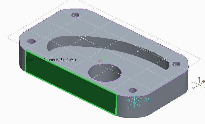
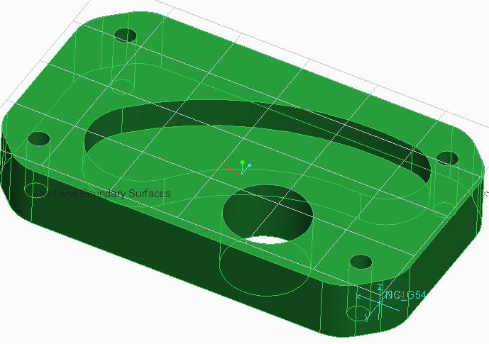
19 5. Roughing A. Roughing Roughing operation is used to remove the excess material from the stock and roughly cut to the final shape. In general, the result of roughing cut is not very accurate, so finishing operation is recommended after roughing. (When roughing any large hole, the size of the hole is slightly smaller than the actual size, which can be used for press-fit the bearing.) In Creo, this sequence uses Mill Window, and try to remove any material that is not projected by the specified window. The roughing operation requires Mill Window. a) Click Mill Window b) Click the top surface c) If necessary, specify the depth 18


20 Select Roughing d) Click Ok Select the tool Select References go to References page Select Mill Window in model tree Set Parameters (for detail, click ) 19

21 1. Cut_Feed Cutting speed. It depend on material, RPM, and diameter. For aluminum 6061, IPM was used for 3/8 inch end mill operation. 2. Free_Feed / Retract_Feed They are not required but recommended to reduce operation time. In general, machine in ESPL can handle about IPM. 3. Step_Over 1/3 of the diameter of the tool or less is generally recommended. 4. Max_Step_Depth It depend on the material of the tool and number of flute. The operation time largely depend on this parameter 20

22 Click Ok to create operation Play the path to check 21

23 B. Volume Roughing Volume roughing is used for same purpose as Roughing, but it uses Mill Volume instead. Simply, it creates the path to remove the mill volume as much as possible. It is simple and easy to use, so it is recommended for general purpose machining. Volume Roughing uses Mill Volume a. Create a volume using extrude, revolve, sweep, or other operation. (I just used extrude to create rectangular cylinder. The size does not matter as long as it covers all the features, but the height should be the height of the referenced model.) b. Trim the volume using referenced model Click Trim Click Referenced Model (not the mill volume) 22

24 modify using extrude or other tools to remove unnecessary volumes 23

25 c. Click Ok Note: To redefine or edit the mill volume, right-click the extrude and click redefine mill volume Click Volume Rough Select the Tool Select reference Go to Reference tab click Select items Click Mill Volume on the screen 24
")

 Set")
26 (Make sure, Machining Reference start with Quilt ) (If it is set to extrude, left-click and remove the reference and click the mill volume on the screen) Set Parameters 25
27 1. Cut_Feed Cutting speed. It depend on material, RPM, and diameter. For aluminum 6061, IPM was used for 3/8 inch end mill operation. 2. Arc_Feed If the value is not given, default is Cut_Feed. 3. Free_Feed / Retract_Feed / Traverse_Feed They are not required but recommended to reduce operation time. In general, machine in ESPL can handle about IPM. Plunge_Feed The rate of plunging tool into the material. It depend on the material, material of the tool, and the number of flute. In general, it is lower than Cut_Feed. 4. Step_Over 1/3 of the diameter of the tool or less is generally recommended. 5. Max_Step_Depth It depend on the material of the tool and number of flute. The operation time largely depend on this parameter Click Ok. Play the path and check 26


28 Note: The path is more visible if you hide the mill volume. 27
29 28


30 C. Profile Milling Profile milling is generally used to create outer shape/profile from the stock material. When using this operation, you should be careful on the set-up and the path, so that the tool does not run into the vice or the platform. This operation is great to create large hole, enlarge any hole, or profile inner arc/shape. Click Profile Milling Select the tool Select the reference surfaces Ctrl Click multiple surfaces Set Parameters 29

31 1. Cut_Feed Cutting speed. It depend on material, RPM, and diameter. For aluminum 6061, IPM was used for 3/8 inch end mill operation. 2. Arc_Feed If the value is not given, default is Cut_Feed. 3. Free_Feed / Retract_Feed They are not required but recommended to reduce operation time. In general, machine in ESPL can handle about IPM. Plunge_Feed The rate of plunging tool into the material. It depend on the material, material of the tool, and the number of flute. In general, it is lower than Cut_Feed. 4. Step_Depth It depend on the material of the tool and number of flute. The operation time largely depend on this parameter Click Ok Play the path and check 30

 Note: When selecting the reference, it is possible to select boundary by")
32 (In general, the above operation is impossible since the piece must be held by the vice, but the tool will run into the vice. In real application, you must set the depth and make a space for vice grip.) Note: When selecting the reference, it is possible to select boundary by using shift when clicking the surface. 31

33 32

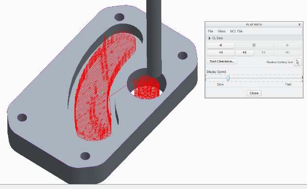
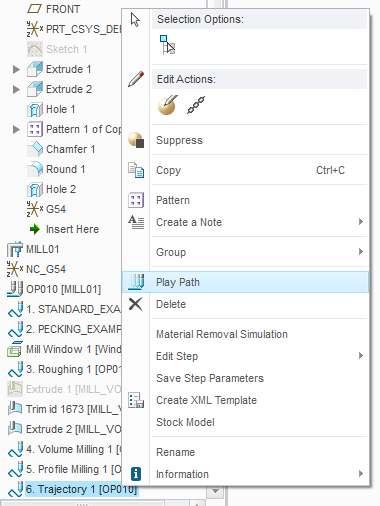
34 D. Trajectory Milling Trajectory milling simply create a path along the chosen trajectory. In this guide, trajectory milling does not cut/remove any material, but it can be generally used to create chamfer or round feature. Click Trajectory Milling Select the tool Set Parameters Click the top surface of the part Select Tool Motions a. Go to Tool Motion tab b. Click the type of cut (Curve Cut, Drive Surface Cut, Follow Curve) (example is Curve Cut) 33


35 c. Select the trajectory d. To make a chain, click detail e. Using Ctrl, click chain of trajectory 34


36 6. Click Ok f. To add more trajectory, click insert here, and repeat g. Click Ok Play the path and check 35

37 36
38 E. Finishing Finishing is an accurate operation to finalize the piece with lowest tolerance available. It is important to remember this operation is not meant to remove the large amount of material. Instead, it runs through all the surface and tries to remove any rough surface. It is generally used at the end of any end-mill operation. The finishing operation requires Mill Window. Click Finishing Select the tool Select References go to References page Select Mill Window in model tree Set Parameters (for detail, click ) 37
39 Click Ok to create operation Play the path to check 38


40 6. Export the G-Code A. Single Operation Go back to Manufacturing tab Select Save a CL File Click NC Sequence from menu 39

 Click File Check")
41 Click the operation that you want to export (4. Volume Milling 1 for example) Click File Check MCD File 40

42 Click Done and save Click Done 41

43 Click UNCX01.P12 Close the log file, and click Done Output Go to Working Directory 42
, and pause the machine until the tool-change is done (M06). This is used for CNC with ATC (Automatic Tool Change).")
44 The g-code file extension is.tap file. Open.tap file in Notepad. ( volume_milling_1.tap for example) Bring this file to CNC machine. Note: Before running the code, the machine will stop at N25. This is because T1 M06 means change the tool to tool #1 (T1), and pause the machine until the tool-change is done (M06). This is used for CNC with ATC (Automatic Tool Change). Otherwise, machine will just stop until start button is pressed again, so that people can manually change the tool. In this case, it is ok to delete the line N25 before starting the operation. 43


45 B. Multiple Operation Click Save CL File for a Set Click Create in the menu Enter the set name, and click the checkmark Check necessary operations in a set Click Done Sel (Done Selection) Note: You can also modify the set or create different set. 44


46 Select the Set (Set01) Click Display and Done to generate the path. Check the path before output. Click File and check MCD File Click Done Save the set 45


47 Click Done Click UNCX01.P12 Close the log file, and click Done Output Go to working directory, and find.tap file for the set 46

48 Bring this file to CNC machine. 47
Belt Buckle A. Create Rectangle. Step 1. If necessary start a new Mastercam file, click New
 Mastercam 2017 Chapter 35 Belt Buckle A. Create Rectangle. Step 1. If necessary start a new Mastercam file, click New (Ctrl-N) on the Quick Access Toolbar QAT. Step 2. On the Wireframe tab click Rectangle.
VisualCAM 2018 for SOLIDWORKS-TURN Quick Start MecSoft Corporation
 2 Table of Contents Useful Tips 4 What's New 5 Videos & Guides 6 About this Guide 8 About... the TURN Module 8 Using this... Guide 8 Getting Ready 10 Running... VisualCAM for SOLIDWORKS 10 Machining...
Brief Introduction to MasterCAM X4
 Brief Introduction to MasterCAM X4 Fall 2013 Meung J Kim, Ph.D., Professor Department of Mechanical Engineering College of Engineering and Engineering Technology Northern Illinois University DeKalb, IL
PART 1: BASIC MACHINING
 PART 1: BASIC MACHINING CAM Tutorial CREO PARAMETRIC 1.0 week 1 Part 1 CREATING A MANUFACTURING MODEL In this Lesson you will create a Manufacturing Model by assembling the Design Model. The Design Model
CNC Programming Simplified. EZ-Turn / TurnMill Tutorial.
 CNC Programming Simplified EZ-Turn / TurnMill Tutorial www.ezcam.com Copyright Notice This manual describes software that contains published and unpublished works of authorship proprietary to EZCAM Solutions,
MASTERCAM DYNAMIC MILLING TUTORIAL. June 2018
 MASTERCAM DYNAMIC MILLING TUTORIAL June 2018 MASTERCAM DYNAMIC MILLING TUTORIAL June 2018 2018 CNC Software, Inc. All rights reserved. Software: Mastercam 2019 Terms of Use Use of this document is subject
VisualMILL Getting Started Guide
 VisualMILL Getting Started Guide Welcome to VisualMILL Getting Started Guide... 4 About this Guide... 4 Where to go for more help... 4 Tutorial 1: Machining a Gasket... 5 Introduction... 6 Preparing the
CNC Programming Simplified. EZ-Turn Tutorial.
 CNC Programming Simplified EZ-Turn Tutorial www.ezcam.com Copyright Notice This manual describes software that contains published and unpublished works of authorship proprietary to EZCAM Solutions, Inc.
Conversational Programming for 6000M, 5000M CNC
 Conversational Programming for 6000M, 5000M CNC www.anilam.com P/N 70000486F - Contents Section 1 - Introduction Section 2 - Conversational Mode Programming Hot Keys Programming Hot Keys... 2-1 Editing
Mill Level 1 Training Tutorial
 To order more books: Call 1-800-529-5517 or Visit www.inhousesolutions.com or Contact your Mastercam dealer Mastercam X 5 Copyright: 1998-2010 In-House Solutions Inc. All rights reserved Software: Mastercam
SETTING UP PRO/NC IN PREPARATION FOR CREATING TOOL PATHS
 SETTING UP PRO/NC IN PREPARATION FOR CREATING TOOL PATHS PTC Technical Support - Advanced Manufacturing Technique 140 Kendrick St Needham, MA, USA 800-477-6435 Introduction This document introduces the
Feature-based CAM software for mills, multi-tasking lathes and wire EDM. Getting Started
 Feature-based CAM software for mills, multi-tasking lathes and wire EDM www.featurecam.com Getting Started FeatureCAM 2015 R3 Getting Started FeatureCAM Copyright 1995-2015 Delcam Ltd. All rights reserved.
Vectric Cut 3D (Frogmill)
") II. Subtractive Rapid Prototyping / VECTRIC CUT 3D (Frogmill) SUBTRACTIVE RAPID PROTOTYPING Vectric Cut 3D (Frogmill) INTERFACE: VECTRIC CUT 3D Model: Frogmill Size: W3050 x D1828 X H419 Material: EPS
II. Subtractive Rapid Prototyping / VECTRIC CUT 3D (Frogmill) SUBTRACTIVE RAPID PROTOTYPING Vectric Cut 3D (Frogmill) INTERFACE: VECTRIC CUT 3D Model: Frogmill Size: W3050 x D1828 X H419 Material: EPS
TRAINING GUIDE MILL-LESSON-FBM-1 FBM MILL AND FBM DRILL
 TRAINING GUIDE MILL-LESSON-FBM-1 FBM MILL AND FBM DRILL Mastercam Training Guide Objectives Previously in Mill-Lesson-6 and Mill-Lesson-7 geometry was created and machined using standard Mastercam methods.
3 AXIS STANDARD CAD. BobCAD-CAM Version 28 Training Workbook 3 Axis Standard CAD
 3 AXIS STANDARD CAD This tutorial explains how to create the CAD model for the Mill 3 Axis Standard demonstration file. The design process includes using the Shape Library and other wireframe functions
Polar coordinate interpolation function G12.1
 Polar coordinate interpolation function G12.1 On a Turning Center that is equipped with a rotary axis (C-axis), interpolation between the linear axis X and the rotary axis C is possible by use of the G12.1-function.
Modeling a Gear Standard Tools, Surface Tools Solid Tool View, Trackball, Show-Hide Snaps Window 1-1
 Modeling a Gear This tutorial describes how to create a toothed gear. It combines using wireframe, solid, and surface modeling together to create a part. The model was created in standard units. To begin,
Chapter 39. Mastercam Jewelry Box Tray. A. Sketch Tray Circle. B. Twin Edge Point Circles. Mastercam 2017 Tray Jewelry Box Page 39-1
 Mastercam 2017 Chapter 39 A. Sketch Tray Circle. Jewelry Box Tray Step 1. If necessary start a new Mastercam file, click New (Ctrl-N) on the Quick Access Toolbar QAT. Step 2. On the Wireframe tab click
Mastercam X9 for SOLIDWORKS
 Chapter 21 CO2 Shell Car Mastercam X9 for SOLIDWORKS A. Enable Mastercam for SOLIDWORKS. Step 1. If necessary, turn on Mastercam for SOLIDWORKS, click the flyout of Options on the Standard toolbar and
Conversational Programming for 6000i CNC
 Conversational Programming for 6000i CNC www.anilam.com P/N 634 755-22 - Contents Section 1 - Introduction Section 2 - Conversational Mode Programming Hot Keys Programming Hot Keys... 2-1 Editing Keys...
Simulating Drilling Processes with DEFORM-3D
 Simulating Drilling Processes with DEFORM-3D Due to the number of revolutions of a drill necessary to establish characteristic behavior, drilling simulations in DEFORM are time consuming. Therefore, every
Profile Modeler Profile Modeler ( A SuperControl Product )
") Profile Modeler ( A SuperControl Product ) - 1 - Index Overview... 3 Terminology... 3 Launching the Application... 4 File Menu... 4 Loading a File:... 4 To Load Multiple Files:... 4 Clearing Loaded Files:...
Profile Modeler ( A SuperControl Product ) - 1 - Index Overview... 3 Terminology... 3 Launching the Application... 4 File Menu... 4 Loading a File:... 4 To Load Multiple Files:... 4 Clearing Loaded Files:...
Introduction to MasterCAM X4,7
 Introduction to MasterCAM X4,7 Spring 2014 By Meung J. Kim, Ph.D., Professor Department of Mechanical Engineering Northern Illinois University 1 Preliminaries C-Plane: flat Construction plane that can
Using Delcam Powermill
 Written by: John Eberhart & Trevor Williams DM Lab Tutorial Using Delcam Powermill Powermill is a sophistical tool path generating software. This tutorial will walk you through the steps of creating a
RhinoCAM 2018 MILL Quick Start Guide. MecSoft Corporation
 2 Table of Contents About this Guide 4 1 Useful... Tips 4 2 About... the MILL Module 4 3 Using this... Guide 5 Getting Ready 6 1 Running... RhinoCAM 2018 6 2 About... the RhinoCAM Display 6 3 Launch...
EZ-Mill EXPRESS TUTORIAL 2. Release 13.0
 E-Mill EPRESS TUTORIAL 2 Release 13.0 Copyright Notice This manual describes software that contains published and unpublished works of authorship proprietary to ECAM Solutions, Inc. It is made available
Fig. 2 Mastercam 2020 Spinning Top SW 19 to MCam20 TOOLPATHS Page 13-1
 Mastercam 2020 Chapter 13 Spinning Top SOLIDWORKS 19 to Mastercam 2020 A. Open File in Mastercam 2020. Step 1. If necessary, save your Handle and Flywheel parts file in SOLIDWORKS. Step 2. In Mastercam
TOOLPATHS TRAINING GUIDE. Sample. Distribution. not for MILL-LESSON-4-TOOLPATHS DRILL AND CONTOUR
 TOOLPATHS TRAINING GUIDE MILL-LESSON-4-TOOLPATHS DRILL AND CONTOUR Mill-Lesson-4 Objectives You will generate a toolpath to machine the part on a CNC vertical milling machine. This lesson covers the following
CAM Tutorial CREO PARAMETRIC 1.0 week 2 Part 3. Profile the outside of the bracket which you used in the Basic Machining Lesson.
 CAM Tutorial CREO PARAMETRIC 1.0 week 2 Part 3 PART 3: PROFILING CREATING A BASIC PATH Profile the outside of the bracket which you used in the Basic Machining Lesson. Before starting this tutorial: Ensure
TRAINING GUIDE MILL-LESSON-FBM-2 FBM MILL AND FBM DRILL
 TRAINING GUIDE MILL-LESSON-FBM-2 FBM MILL AND FBM DRILL Mastercam Training Guide Objectives This lesson will use the same Feature Based Machining (FBM) methods used in Mill-Lesson- FBM-1, how ever this
SolidCAM Training Course: Turning & Mill-Turn
 SolidCAM Training Course: Turning & Mill-Turn imachining 2D & 3D 2.5D Milling HSS HSM Indexial Multi-Sided Simultaneous 5-Axis Turning & Mill-Turn Solid Probe SolidCAM + SolidWorks The Complete Integrated
Penny Hockey SOLIDWORKS 17 to Mastercam 2017 A. Open File in Mastercam Step 1. If necessary, save your BASE file in SOLIDWORKS.
 Mastercam 2017 Chapter 22 Chapter 7 Penny Hockey SOLIDWORKS 17 to Mastercam 2017 A. Open File in Mastercam 2017. Step 1. If necessary, save your BASE file in SOLIDWORKS. Step 2. In Mastercam 2017, click
IEEM 215. Manufacturing Processes I Introduction to the ARIX CNC milling machine
 IEEM 215. Manufacturing Processes I Introduction to the ARIX CNC milling machine The image below is our ARIX Milling machine. The machine is controlled by the controller. The control panel has several
2. Open VCarve Pro. Click the Open an existing file button and select your file.
 VCarve Pro This software is used for 2D design and calculation of 2D and 2.5D toolpaths for cutting parts on a CNC Router. The software can import 2D designs from other programs such as FormZ, Rhino and
What s new in EZCAM Version 18
 CAD/CAM w w w. e z c a m. com What s new in EZCAM Version 18 MILL: New Curve Machining Wizard A new Curve Machining Wizard accessible from the Machining menu automates the machining of common part features
FAGOR AUTOMATION MC TRAINING MANUAL
 FAGOR AUTOMATION MC TRAINING MANUAL ACER MC TRAINING MANUAL 8 holes 1/2" depth grid pattern R0.125 1.5 6 unit: inch R0.25 4 1.25 2 2.675 1/2" depth rectangular pocket 1/2" depth circular pocket R0.75 8
Release notes for: NCG CAM v Date: 12/01/2017
 NCG CAM Solutions Ltd are pleased to release There are some new features, enhancements to existing features, and some problems fixed. Please note that NCG CAM v15.0 will not install on Window XP, or on
MFG12197 FeatureCAM Hands On Milling, turning and mill turn with Feature Based Machining
 MFG12197 FeatureCAM Hands On Milling, turning and mill turn with Feature Based Machining Jeremy Malan Delcam Learning Objectives Learn how to instantly machine parts once their features are defined Learn
4 & 5 Axis Mill Training Tutorials. To order more books: Call or Visit or Contact your Mastercam Dealer
 4 & 5 Axis Mill Training Tutorials To order more books: Call 1-800-529-5517 or Visit www.inhousesolutions.com or Contact your Mastercam Dealer Mastercam X Training Tutorials 4 & 5 Axis Mill Applications
Chapter 36. Mastercam Jewelry Box Fixture. A. Sketch Fixture Rectangle. Step 1. If necessary start a new Mastercam file, click New
 Mastercam 2017 Chapter 36 Jewelry Box Fixture A. Sketch Fixture Rectangle. Step 1. If necessary start a new Mastercam file, click New (Ctrl-N) on the Quick Access Toolbar QAT. Step 2. On the Wireframe
VERO UK TRAINING MATERIAL. 2D CAM Training
 VERO UK TRAINING MATERIAL 2D CAM Training Vcamtech Co., Ltd 1 INTRODUCTION During this exercise, it is assumed that the user has a basic knowledge of the VISI-Series software. OBJECTIVE This tutorial has
Mastercam X6 for SolidWorks Toolpaths
 Chapter 14 Spinning Top Mastercam X6 for SolidWorks Toolpaths A. Insert Handle in New Assembly. Step 1. Click File Menu > New, click Assembly and OK. Step 2. Click Browse in the Property Manager, Fig.
Ladybird Project - Vacuum Mould
 - Vacuum Mould Prerequisite Mould drawn and saved as STL file from Solidworks Focus of the Lesson On completion of this exercise you will have completed: Opening STL file Setting Machining Constraints
Exercise Guide. Published: August MecSoft Corpotation
 VisualCAD Exercise Guide Published: August 2018 MecSoft Corpotation Copyright 1998-2018 VisualCAD 2018 Exercise Guide by Mecsoft Corporation User Notes: Contents 2 Table of Contents About this Guide 4
3D Design with 123D Design
 3D Design with 123D Design Introduction: 3D Design involves thinking and creating in 3 dimensions. x, y and z axis Working with 123D Design 123D Design is a 3D design software package from Autodesk. A
Jewelry Box Lid. A. Sketch Lid Circle. Step 1. If necessary start a new Mastercam file, click FILE Menu > New. Fig. 3
 Mastercam X9 Chapter 39 Jewelry Box Lid A. Sketch Lid Circle. Step 1. If necessary start a new Mastercam file, click FILE Menu > New. Step 2. Click CREATE Menu > Arc > Circle Center Point. Step 3. Key-in
Software designed to work seamlessly with your CNC Masters machine. Made to work with Windows PC. Works with standard USB
 Software designed to work seamlessly with your CNC Masters machine Made to work with Windows PC Works with standard USB Clutter free interface. The software is engineered for the machine so you don t have
Tutorial: Connecting Rod
 Tutorial: Connecting Rod Cut2D Disclaimer All CNC machines (routing, engraving, and milling) are potentially dangerous and because Vectric Ltd. has no control over how the software described in this manual
Conversational Programming for 6000M, 5000M CNC
 Conversational Programming for 6000M, 5000M CNC www.anilam.com P/N 70000486E - Warranty Warranty ANILAM warrants its products to be free from defects in material and workmanship for one (1) year from date
VisualCAM 2018 MILL Quick Start Guide. MecSoft Corporation
 2 Table of Contents About this Guide 4 1 Useful... Tips 4 2 About... the MILL Module 4 3 Using this... Guide 5 Getting Ready 6 1 Running... VisualCAM 2018 6 2 About... the VisualCAM Display 6 3 Launch...
Prismatic Machining Overview What's New Getting Started User Tasks
 Prismatic Machining Overview Conventions What's New Getting Started Enter the Workbench Create a Pocketing Operation Replay the Toolpath Create a Profile Contouring Operation Create a Drilling Operation
Instructions. elucad Software. Version en Translation of the original instructions. Retain for future use.
 Instructions Version 3.0.0 en Translation of the original instructions. Retain for future use. elusoft GmbH Breitwasenring 4 D 72135 Dettenhausen Phone +49(0)7157 526-6500 Fax +49(0)7157 526-6526 info@elusoft.de
Introduction to Solid Modeling
 Introduction to Solid Modeling Parametric Modeling 1 Why draw 3D Models? 3D models are easier to interpret. 3D models can be used to perform engineering analysis, finite element analysis (stress, deflection,
Multi-Pockets Machining
 CATIA V5 Training Foils Multi-Pockets Machining Version 5 Release 19 January 2009 EDU_CAT_EN_MPG_FF_V5R19 1 About this course Objectives of the course Upon completion of this course you will be able to
Conversational Programming for 6000i CNC
 Conversational Programming for 6000i CNC January 2008 Ve 01 634755-21 1/2008 VPS Printed in USA Subject to change without notice www.anilam.com P/N 634755-21 - Warranty Warranty ANILAM warrants its products
Edgecam Getting Started Guide
 Edgecam Getting Started Guide Getting Started October 2016 1 Contents Contents... 2 Introduction... 4 About this Guide... 4 Other Resources... 5 What is Edgecam?... 6 Supporting Applications... 7 Installing
Mastercam X6 for SolidWorks Toolpaths
 Chapter 21 CO2 Shell Car Mastercam X6 for SolidWorks Toolpaths A. Enable Mastercam for SolidWorks. Step 1. If necessary, turn on Mastercam for SolidWorks, click Tools Menu > Add-Ins. Step 2. In the dialog
Tutorial 3 Model Locomotive Name plate
 Getting Started With Tutorial 3 Model Locomotive Name plate Cut2D Disclaimer All CNC machines (routing, engraving, and milling) are potentially dangerous and because Vectric Ltd. has no control over how
SEER-3D: An Introduction
 SEER-3D SEER-3D allows you to open and view part output from many widely-used Computer-Aided Design (CAD) applications, modify the associated data, and import it into SEER for Manufacturing for use in
Lab Assignment #1: Introduction to Creo ME 170
 Lab Assignment #1: Introduction to Creo ME 170 Instructor: Mike Philpott (email: mphilpot@illinois.edu) Date Due: One week from Start Day of Lab (turn in deadline 11pm night before next lab) Make sure
itnc 530 NC Software English (en) 8/2006
 8/2006") adp h" itnc 530 NC Software 340 490-03 340 491-03 340 492-03 340 493-03 340 494-03 English (en) 8/2006 The smart.nc Pilot... is your concise programming guide for the new smart.nc operating mode of the
adp h" itnc 530 NC Software 340 490-03 340 491-03 340 492-03 340 493-03 340 494-03 English (en) 8/2006 The smart.nc Pilot... is your concise programming guide for the new smart.nc operating mode of the
Dynamic Milling. March 2015
 Dynamic Milling March 2015 Mastercam X9 Dynamic Milling TERMS OF USE Date: March 2015 Copyright 2015 CNC Software, Inc. All rights reserved. Software: Mastercam X9 Use of this document is subject to the
CATIA V5 Training Foils
 CATIA V5 Training Foils Prismatic Machining Version 5 Release 19 January 2009 EDU_CAT_EN_PMG_FF_V5R19 1 About this course Objectives of the course Upon completion of this course you will be able to: -
Manufacturing Processes with the Aid of CAD/CAM Systems AMEM 405
 AMEM 405 slide 1 Manufacturing Processes with the Aid of CAD/CAM Systems AMEM 405 Dr. Sotiris Omirou AMEM 405 slide 2 CONTENTS 1. CAD/CAM definition 2. Review of Milling Process 3. Know The CNC Machine
CNC ROUTER - GRANITE 1200 X 1600 X 200
 KRITELAS ATHANASIOS CNC MANIFACTURE FARMAKI 23 STR- 52100 KASTORIA - GREECE TEL: ++30 2467023619 Fax: ++30 2467023886 www.servo.gr - email: krit01@otenet.gr CNC ROUTER - GRANITE 1200 X 1600 X 200 Greece
Foam Casualty NCGen User Manual
 Foam Casualty NCGen User Manual Table of contents 1.0 Introduction 2.0 Definitions 3.0 Installation 4.0 Generation 4.1 Lines 4.2 Face(s) 4.3 Face to Pocket 4.4 Surfaces 4.5 Wire Tool Introduction 4.6 Wire
WHAT'S NEW IN MASTERCAM 2018 FOR SOLIDWORKS
 WHAT'S NEW IN MASTERCAM 2018 FOR SOLIDWORKS March 2017 WHAT'S NEW IN MASTERCAM 2018 FOR SOLIDWORKS March 2017 2017 CNC Software, Inc. All rights reserved. Software: Mastercam 2018 for SOLIDWORKS Terms
ADVANCED TECHNIQUES APPENDIX A
 A P CONTENTS þ Anilam þ Bridgeport þ Fanuc þ Yasnac þ Haas þ Fadal þ Okuma P E N D I X A ADVANCED TECHNIQUES APPENDIX A - 1 APPENDIX A - 2 ADVANCED TECHNIQUES ANILAM CODES The following is a list of Machinist
Century Star Turning CNC System. Programming Guide
 Century Star Turning CNC System Programming Guide V3.5 April, 2015 Wuhan Huazhong Numerical Control Co., Ltd 2015 Wuhan Huazhong Numerical Control Co., Ltd Preface Preface Organization of documentation
TRAINING GUIDE. Sample not. for Distribution LATHE-LESSON-1 FACE, ROUGH, FINISH AND CUTOFF
 TRAINING GUIDE LATHE-LESSON-1 FACE, ROUGH, FINISH AND CUTOFF Mastercam Training Guide Objectives You will create the geometry for Lathe-Lesson-1, and then generate a toolpath to machine the part on a CNC
Mach4 CNC Controller Mill Programming Guide Version 1.1 Build 3775
 Mach4 CNC Controller Mill Programming Guide Version 1.1 Build 3775 Copyright 2014 Newfangled Solutions, Artsoft USA, All Rights Reserved The following are registered trademarks of Microsoft Corporation:
Autodesk Fusion 360 Training: The Future of Making Things Attendee Guide
 Autodesk Fusion 360 Training: The Future of Making Things Attendee Guide Abstract After completing this workshop, you will have a basic understanding of editing 3D models using Autodesk Fusion 360 TM to
Dolphin 3DCAM Help. Copyright <2018> by <Dolphin Cadcam Systems Ltd>. V All Rights Reserved.
 Copyright by . V1.020216 All Rights Reserved. Table of Contents Introduction... 3 Getting Started... 4 The Ribbon Toolbar... 5 File... 6 Geom... 9 Solids... 24 View...
Lesson 4 Introduction To Programming Words
 Lesson 4 Introduction To Programming Words All CNC words include a letter address and a numerical value. The letter address identifies the word type. The numerical value (number) specifies the value of
BobCAM for SolidWorks June 4, 2010
 BobCAM for SolidWorks June 4, 2010 Copyright 2010 by BobCAM Inc., All rights reserved. No part of this work may be reproduced or transmitted in any form or by any means, electronic or mechanical, including
SolidWorks Intro Part 1b
 SolidWorks Intro Part 1b Dave Touretzky and Susan Finger 1. Create a new part We ll create a CAD model of the 2 ½ D key fob below to make on the laser cutter. Select File New Templates IPSpart If the SolidWorks
Mach4 CNC Controller Mill Programming Guide Version 1.0
 Mach4 CNC Controller Mill Programming Guide Version 1.0 1 Copyright 2014 Newfangled Solutions, Artsoft USA, All Rights Reserved The following are registered trademarks of Microsoft Corporation: Microsoft,
Inventor 201. Work Planes, Features & Constraints: Advanced part features and constraints
 Work Planes, Features & Constraints: 1. Select the Work Plane feature tool, move the cursor to the rim of the base so that inside and outside edges are highlighted and click once on the bottom rim of the
G & M Code REFERENCE MANUAL. Specializing in CNC Automation and Motion Control
 REFERENCE MANUAL Specializing in CNC Automation and Motion Control 2 P a g e 11/8/16 R0163 This manual covers definition and use of G & M codes. Formatting Overview: Menus, options, icons, fields, and
Mach4 CNC Controller Lathe Programming Guide Version 1.0
 Mach4 CNC Controller Lathe Programming Guide Version 1.0 1 Copyright 2014 Newfangled Solutions, Artsoft USA, All Rights Reserved The following are registered trademarks of Microsoft Corporation: Microsoft,
The ProtoTRAK Parasolid Converter Operating Manual
 The ProtoTRAK Parasolid Converter Operating Manual Document: P/N 28070 Version: 042216 Parasolid for Mills Compatible with offline and SMX ProtoTRAK Control models Southwestern Industries, Inc. 2615 Homestead
This document shows you how to set the parameters for the ModuleWorks Material Removal Simulation.
 Table of Contents Introduction:... 3 Select Profile:... 4 Tool Table - Create Tool(s)... 5 Tool properties:... 5 Tool Color R/G/B:... 6 Simulation Configurations - create stock... 7 What if plugin is greyed
Kuang-Hua Chang, Ph.D. MACHINING SIMULATION USING SOLIDWORKS CAM 2018 SDC. Better Textbooks. Lower Prices.
 Kuang-Hua Chang, Ph.D. MACHINING SIMULATION USING SOLIDWORKS CAM 2018 SDC PUBLICATIONS Better Textbooks. Lower Prices. www.sdcpublications.com Powered by TCPDF (www.tcpdf.org) Visit the following websites
Getting Started Manual Version 24 Mill Standard/Pro January 2011
 Getting Started Manual Version 24 Mill Standard/Pro January 2011 Copyright 2011 by BobCAD-CAM Inc., All rights reserved. No part of this work may be reproduced or transmitted in any form or by any means,
Introduction to the Work Coordinate System (WCS) April 2015
 April 2015") Introduction to the Work Coordinate System (WCS) April 2015 Mastercam X9 Introduction to WCS TERMS OF USE Date: April 2015 Copyright 2015 CNC Software, Inc. All rights reserved. Software: Mastercam X9
Introduction to the Work Coordinate System (WCS) April 2015 Mastercam X9 Introduction to WCS TERMS OF USE Date: April 2015 Copyright 2015 CNC Software, Inc. All rights reserved. Software: Mastercam X9
Advanced Part Machining
 CATIA V5 Training Exercises Advanced Part Machining Version 5 Release 19 January 2009 EDU_CAT_EN_AMG_FX_V5R19 1 Table of Contents (1/2) Exercise Presentation 4 CATIA Settings 5 Multi-Axis Flank Contouring:
What's New in BobCAD-CAM V29
 Introduction Release Date: August 31, 2016 The release of BobCAD-CAM V29 brings with it, the most powerful, versatile Lathe module in the history of the BobCAD-CAM software family. The Development team
BobCAD-CAM FAQ #50: How do I use a rotary 4th axis on a mill?
 BobCAD-CAM FAQ #50: How do I use a rotary 4th axis on a mill? Q: I ve read FAQ #46 on how to set up my milling machine. How do I enable 4th axis to actually use it? A: Enabling 4th axis in the machine
3ds Max Cottage Step 1. Always start out by setting up units: We re going with this setup as we will round everything off to one inch.
 3ds Max Cottage Step 1 Always start out by setting up units: We re going with this setup as we will round everything off to one inch. File/Import the CAD drawing Be sure Files of Type is set to all formats
Setting up the Roland EGX-300 and EngraveLab to cut IkonicsMetal
 Setting up the Roland EGX-300 and EngraveLab to cut IkonicsMetal Setting Up the Roland EGX-300: 1. Power unit off 2. Remove any existing tools and install the 11/64 solid collet to the bottom of the spindle
TRAINING GUIDE. Sample Only. not to be used. for training MILL-LESSON-15 CORE ROUGHING, WATERLINE, AND SURFACE FINISH LEFTOVER
 TRAINING GUIDE MILL-LESSON-15 CORE ROUGHING, WATERLINE, AND SURFACE FINISH LEFTOVER Mastercam Training Guide Objectives You will use a provided model for Mill-Lesson-15, then generate the toolpaths to
What's New in CAMWorks 2016
 Contents (Click a link below or use the bookmarks on the left) About this Version (CAMWorks 2016 SP3)... 2 Supported Platforms 2 Resolved CPR s document 2 About this Version (CAMWorks 2016 SP2.2) 3 Supported
EXPERIENCE THE POWER. THE NEW BobCAD-CAM V31. We have upgraded the entire customer experience to be more intuitive, modern and efficient.
 01 EXPERIENCE THE POWER V31 Whether you re a leading manufacturer or just starting out, BobCAD-CAM has the features, training & support you need to machine better parts FASTER and EASIER, for LESS. THE
Copyright 2019 OPEN MIND Technologies AG
 Copyright 2019 OPEN MIND Technologies AG This document applies to hypermill and hypermill SHOP Viewer. It contains notes about recent changes that are not described in the manual. All rights reserved.
Getting Started. Tutorial 2 Flat Bottom V-Carving. A quick start guide for VCarve Pro & Aspire users. Vectric Ltd. Document V.6.0 V3.
 Getting Started A quick start guide for VCarve Pro & Aspire users Vectric Ltd. Document V.6.0 V3.0 Tutorial 2 Flat Bottom V-Carving Getting Started with Aspire & VCarve Pro Disclaimer All CNC machines
INTRODUCTION TO MULTIAXIS TOOLPATHS
 INTRODUCTION TO MULTIAXIS TOOLPATHS June 2017 INTRODUCTION TO MULTIAXIS TOOLPATHS June 2017 2017 CNC Software, Inc. All rights reserved. Software: Mastercam 2018 Terms of Use Use of this document is subject
300S READOUTS REFERENCE MANUAL
 300S READOUTS REFERENCE MANUAL 300S Key Layout 1 Display Area 2 Soft keys 3 Power Indicator light 4 Arrow Keys: Use the UP/DOWN keys to adjust the screen contrast. 5 Axis Keys 6 Numeric Keypad 7 ENTER
Licom Systems Ltd., Training Course Notes. 3D Surface Creation
 , Training Course Notes Work Volume and Work Planes...........................1 Overview..........................................1 Work Volume....................................1 Work Plane......................................1
SolidWorks 2½D Parts
 SolidWorks 2½D Parts IDeATe Laser Micro Part 1b Dave Touretzky and Susan Finger 1. Create a new part In this lab, you ll create a CAD model of the 2 ½ D key fob below to make on the laser cutter. Select
Autodesk Inventor - Basics Tutorial Exercise 1
 Autodesk Inventor - Basics Tutorial Exercise 1 Launch Inventor Professional 2015 1. Start a New part. Depending on how Inventor was installed, using this icon may get you an Inch or Metric file. To be