CTS (Camera Tracking System) User Manual. Compact all in one solution to add vision to your project.
|
|
|
- Bryce George
- 6 years ago
- Views:
Transcription
1 CTS (Camera Tracking System) User Manual Compact all in one solution to add vision to your project. Copyright ThinkSmallThings 2013
2 Revision History Date Version Author Description 01/10/2013 V1.0 Claudiu G. Initial release 01/21/2013 V1.1 Claudiu G. Add Training mode References [1] Online documentation: [2] OV7670 image sensor datasheet: [3] LPC1343 microcontroller: [4] AL422B FIFO memory:
3 Index 1 Introduction Overview Scope Warranty and Limitation of Liability Proprietary information CTS solution Overview Communicating with CTS Hardware overview Hardware details Specifications and ratings Board details UART JTAG Configuration control commands Basic Help System Configuration List Settings Copy EEPROM to SRAM Copy SRAM to EEPROM Dump settings (hex) Verify configuration UART Configuration Check current speed List available serial port speed settings Change serial port speed Check current version Check status for various commands Image control commands Basic Help Automated White Balance (AWB) AWB control Check AWB status Change AWB setting Brightness Brightness control Check Brightness status Change Brightness setting Contrast Contrast control Check Contrast status Change Contrast setting Gamma Gamma control Check Gamma status Change Gamma setting Saturation Saturation control Check Saturation status Change Saturation setting... 25
4 5.7 Orientation Orientation control Check Orientation status Change Orientation setting Resolution Resolution control Check Resolution status Change Resolution setting Sharpness Sherpness control Check Sharpness status Change Sharpness setting Tracking control commands Basic Help Dump/Capture new frame Capture control Windowed or Normal mode? YUV YUV Black and White (B&W) Tracking Tracking control Windowed or Normal mode? Fast Tracking YUV and Blob data B&W and Blob data Debug and Blob data Blob hex format Blob Info Tracking selected color, debug (experimental) Tracking selected color (hex) Tracking selected color (ASCII) YUV Class YUV Class control Copy EEPROM data to SRAM DUMP SRAM (hex) List EEPROM (ascii) List SRAM (ascii) Update values in SRAM Verification Write data from SRAM to EEPROM Learning Color Class Learning control Learn color (ASCII) Learn color Define Learning box size Copy EEPROM to SRAM List SRAM values Store values in EEPROM Setup CTS using CTS Client CTS Client Serial Communication Panel... 43
5 7.1.2 Image Control Settings Panel Tracking Settings Panel Image Review Panel Color Tracking Selection Panel Status Bar Data format Images YUV422 packet YUV211 packet B&W packet Blob details Tracking Multiple blobs Tracking one blob No blobs detected Configuring CTS module Configuration using command line Changing serial speed Changing Image settings Changing Tracking Color Class Training mode Configuration using CTS Client Change image settings Change Tracking Color Class settings Training mode Appendix Troubleshooting Power Communication Image quality... 70
6 Copyright/Licensing/Disclaimer Info CTS hardware Copyright 2013 Claudiu Georgescu CTS Client PC Software Copyright 2013 Claudiu Georgescu All material in this document is Copyright 2013 by Claudiu Georgescu Both CTS and CTS Client PC software are licensed under the GNU General Public License. If interested in an alternative licensing scheme, please contact Claudiu The CTS solution is distributed in the hope that it will be useful. However, no warranties, either expressed or implied, are made regarding the operation, use or results of this system. The CTS should not be used in any life-critical applications.
7 1 Introduction 1.1 Overview One of the major limitations of getting a system interact with the environment is translating a continuous stream of information (e.g.: images in this case) in structured information that make sense and is easy to use, usually by applying one or more image processing algorithms to select only the details required. While there are already available solutions on the market, most of them require large amounts of processing power making them prohibitive for regular use where space and power is a premium. This is why solutions like CTS were designed. 1.2 Scope This document is intended to provide information of how CTS solution can be used. This manual is divided in following sections: - CTS solution details about hardware, feature. - Communicating with CTS how to connect and use CTS. - Control commands details on how to change various configuration parameters using command line. - Image control commands details on how to change various image parameters. - Tracking control commands details on how to initiate tracking of frame dumping or how to setup ColorTracking Table using command line. - CTS Client a description of the provided CTS Client Windows-based solution. - Data formats description of how data returned by CTS is formatted. - Configuring CTS module a how-to for configuring CTS module using command line or CTS Client; - Troubleshooting. 1.3 Warranty and Limitation of Liability No warranty, either express or implied with respect to this product, and specifically disclaims all other warranties, including, without limitation, warranties for merchantability, non- infringement and fitness for any particular purpose. Information contained in this publication regarding device applications and the like is provided only for your convenience and may be superseded by updates. It is your responsibility to ensure that your application meets with your specifications.
8 In no event shall we be liable to the buyer or to any third party for any indirect, incidental, special, consequential, punitive or exemplary damages (including without limitation lost profits, lost savings, or loss of business opportunity) arising out of or relating to any product or service provided or to be provided by us, or the use or inability to use the same. Use of CTS module in life support and/or safety applications is entirely at the buyer s risk, and the buyer agrees to defend, indemnify and hold us harmless from any and all damages, claims, suits, or expenses resulting from such use. Failing to follow the limitations of this product will render the warranty void. 1.4 Proprietary information The information contained in this document is the property of Claudiu Georgescu and may be the subject of patents pending or granted, and must not be copied or disclosed with out prior written permission. The development of CTS product and CTS Client is continuous and published information may not be up to date. It is important to check the current position on All trademarks belong to their respective owners and are recognised and acknowledged.
")
9 2 CTS solution 2.1 Overview Photo 1: Six CTS modules without camera attached. The CTS module is a compact image processing solution based on an OV7670 image sensor from OmniVision, a AL422B three Mbit FIFO memory from Averlogic and a 32 bit ARM processor from NXP (LPC1343) running at 72 Mhz that perform all the image processing tasks and handle high speed communication with a host system (e.g.: PC or any embedded system like: Arduino, Mbed, etc.). This will transfer the highly intensive image processing from the host system that will only need to process the high-level data to perform the desired task. Some of the CTS capabilities: - track up to 8 user-defined different color classes at up to 30 frames/second; - track up to 32 individual blobs/objects of the same color within the same frame; - tracking in QQVGA (160 x 120) and QVGA (320 x 240) at up to 30 frames/second; - provide real-time blobs details over a standard serial port; - dump QQVGA and QVGA full resolution images over a standard serial port; - control over image settings (e.g.: brightness, contrast, saturation, gamma, sharpness, white balance, orientation); - control image resolution; - fully configurable through command-line or provided Windows based client;
10 - high speed serial communication (up to baud); - support both OV7670 and OV7725 cameras; - all settings can be stored in EEPROM; - self-contained, compact (only 50 x 25 mm). For easier configuration, a Windows based application is also provided that will allow easy configuration and basic testing of the CTS module. Following features are available: - capture full resolution images from CTS (QQVGA and QVGA) in YUV422 or YUV211 formats; - access to various image settings (e.g.: brightness, contrast, saturation, gamma, sharpness, white balance, image orientation); - change image resolution; - create color classes using a simple visual interface; - retrieve existing color class information for further fine-tuning; - real-time tracking testing; - image streaming.
11 3 Communicating with CTS All CTS modules communicate with outside world though UART. A wide range of standard speeds are available, however, will recommend to use the highest available speed available on the host side. 3.1 Hardware overview A 32- bit ARM microcontroller is the brain of the entire solution. MCU will connect to a compact image sensor (OV7670) through a large FIFO memory (3 Mbit) that can capture an entire VGA frame Hardware details - MCU: LPC1343 from NXP o 8 Kbytes RAM; o 32 Kbytes Flash; o up to 72 Mhz system clock. - FIFO: AL422B o 3 Mbit storage; o high speed; - Camera: OV7670 o 0.3 Mpixels; o up to VGA format (640 x 480); o fast: 30 FPS; o low power consumption; o compact/light; - EEPROM: 24LC64 or 24LC32 o I2C bus; o High speed; o Low power consumption; o 32 or 64 Kbit storage; - only SMD technology, through hole is only for UART header Specifications and ratings Parameter Conditions Min Typ Max Units Supply voltage (VCC) V Input voltage range Rx Pin GND V Input voltage range RST pin GND V Output voltage range Tx Pin GND V Operating temperature C Storage temperature RH 95% max

12 3.1.3 Board details 3.2 UART CTS boards are designed to follow the FTDI connector, as such, a 5 pin, 0.1 pitch header can be attached. By default, there is no connector or pin header mounted, instead, user can decide what kind of connection will be more suitable based on application and available space. All boards will come configured to baud by default, to change this check Chapter

13 Pin definition is marked on the silkscreen of each board, however, for reference is also shown bellow. UART header pinout on CTS board. Pin Symbol I/O Description 1 GND Power Supply Ground 2 VCC Power Main Voltage supply pin: 4.5 to 5.5 V DC range, nominal 5.0 V. 3 Rx Input Asynchronous Serial Receive pin. Connect this pin to host controller Serial Transmit (Tx) signal. The host transmits commands to the CTS module via this pin. 4 Tx Output Asynchronous Serial Transmit pin. Connect this pin to host controller Serial Receive (Rx) signal. The host receives data from CTS module via this pin. 5 RST Input MCU reset pin. Connect this pin to the host controller to control the restart of CTS module. NOTE: - Only TTL UART adapters can be used and Vcc cannot be higher than 5 Volts. - Using non TTL UART or Vcc higher then 5 Volts it will void the warranty! - CTS do not have reverse polarity protection, user have to pay attention to polarity when connecting to CTS else the module will be damaged. Powering the module using wrong polarity will void the warranty! 3.3 JTAG Due size limitations a standard 10 pin SWD JTAG 0.05 connector can be used for JTAG programming on the CTS ARM boards.

14 ARM SWD JTAG ( x 5 ways) header on CTS board. SWD JTAG ( x 5 ways). NOTE: - JTAG connector is not installed. Please do note that installing it may void your warranty; - Modifying the firmware without using an official version it will void the warranty!
15 4 Configuration control commands Commands used to control various settings of CTS module. By default, CTS will not keep settings between restarts as data will only be stored in SRAM, however, is possible to overwrite SRAM settings with the original/default configuration from EEPROM or to store the latest settings in EEPROM to become persistent. Bellows are the basic commands to handle these operations. 4.1 Basic Help A basic Help feature is implemented by default on CTS for every command. To get help type the command followed by h : h Available commands (use '<command>h'for more details). - Tracking/capture: Frame dumping: F... Tracking: T... YUV Class: C... - Image control: AWB: a... Brightness: b... Contrast: c... GAMMA: g... Orientation: f... Resolution: r... Saturation: s... Sharpness: S... - System control: Configuration: M... Version info: v... UART: u System Configuration There are five commands that handle System Configuration, however, these are very important to store and retrieve settings to or from EEPROM: Mh List or update CTS settings values. List settings (SRAM): M? Copy EEPROM to SRAM: Mr Copy SRAM to EEPROM: Mw Dump settings (hex): Md Verify SRAM vs EEPROM: Mv
16 4.3 List Settings This command will list all the settings stored in the EEPROM in a readable way: M? Version: 0515d134 Camera model: OV7721 Vendor ID: 7F.A2 UART speed: 230,400 Resolution: QVGA (320 x 240) AWB: on Brightness: +25% Contrast: 0 % Saturation: 0 % Gamma: -25% Orientation: normal Sharpness: disable 4.4 Copy EEPROM to SRAM To reload the latest setting stored in the EEPROM to SRAM can use the following command: Mr Note: no confirmation will be provided when running this command. Reloading data from EEPROM to SRAM will not update the configuration! To update the configuration using EEPROM settings a RESET is required. 4.5 Copy SRAM to EEPROM To store configuration between RESTART, settings have to be stored in EEPROM. To do this, can use the following command (this will impact ONLY configuration settings and not Tracking Colour Table data): Mw Note: no confirmation will be provided, however can check using Verify Configuration option (see bellow). 4.6 Dump settings (hex) For easier communication between CTS and other systems/applications, settings can be dumped in hex format using the following command: Md M...
17 The output seen using a terminal will look like above as is returned in hex format. The format of the package is described bellow: Byte1: Byte2: Byte3: Byte4: Byte5: Byte6: Byte7: Byte8: Byte9: Byte10: Byte11: Byte12: Start byte (0x4D) UART speed index Sharpness AWB Orientation Contrast Brightness Saturation Resolution GAMMA End byte (0x00) End byte (0xFF) 4.7 Verify configuration To check if configuration stored in SRAM is the same with the one in EEPROM, the following command can be used: Mv This will return OK if SRAM and EEPROM content is same or ERR if is not. 4.8 UART Configuration By default, CTS module will come configured to run at 115,200 baud, however, speed can be changed from 38,400 to 912,600 baud. To review available option use bellow command: uh UART settings. Current speed: u? List valid speeds: ul Change speed: u<speed code> NOTE: - UART setting change is real-time, when UART speed is changed connection will be terminated! - Change is not stored in EEPROM until 'Mw' command is issued! 4.9 Check current speed To check current speed, the following command will be used: u? UART speed: 230,400
18 4.10 List available serial port speed settings To list available speed settings for serial communication use: ul 0-38, , , , , , Change serial port speed To change serial port speed use: u<speed code> Where: speed code - is one of the following (information available using ul ): 0 38, , , , , ,600 Example: to change serial speed to a 921,600 baud, the following command can be used (note that this is real-time, as such communication with CTS module will be lost when doing this): u5 To check, change host s speed to 921,600 baud then run: u? UART speed: 921,600 NOTE: This change become persistent ONLY if saved in EEPROM after change and before restart Check current version To check current firmware version and AVR chip installed, run the following command: v? The output will look something like (XXYYVMMM):
19 Version: 0409d134 Where XX is the major version (e.g.: 0.4 in above example, running on v0.4 boards); YY is the minor version (e.g.: 09 in above example, will determine build version of the board); V is the version (e.g.: d for Development and p for Production); MMM AVR chip model (e.g.: 134 or LPC1343 in above example. Can also be 176 for LPC1769 or 644 for Atmega644P, etc) Check status for various commands Some commands will accept status check option. Status will be shown for current settings (SRAM) and not for settings stored in EEPROM. For example, to check AWB setting, send: a? This will return AWB current setting: AWB: on To check status for all parameters can use Configuration Check Status (see above).
20 5 Image control commands Commands used to control the image captured by the camera chip. Please note the setting will not change between frames, will remain active until camera module will be restarted unless stored in EEPROM. 5.1 Basic Help A basic Help feature is implemented by default on CTS for every command. To get help type the command followed by h : h Available commands (use '<command>h'for more details). - Tracking/capture: Frame dumping: F... Tracking: T... YUV Class: C... - Image control: AWB: a... Brightness: b... Contrast: c... GAMMA: g... Orientation: f... Resolution: r... Saturation: s... Sharpness: S... - System control: Configuration: M... Version info: v... UART: u Automated White Balance (AWB) Control AWB for camera module AWB control To list all available options: ah Select/Change AWB settings: Current setting: a? Disable AWB: a0 Enable AWB: a1 Sunny: a2 Cloudy: a3 Office: a4 Home: a5
21 5.2.2 Check AWB status To check current status: a? AWB: home Change AWB setting To change current setting: a<mode> Where: mode is active AWB mode. Can be one of the following: 0 disable AWB; 1 enable AWB; 2 enable Sunny WB correction; 3 enable Cloudy WB correction; 4 enable Office WB correction; 5 enable Home WB correction. Example: to enable Sunny WB correction: a2 5.3 Brightness Control image Brightness Brightness control To list all available options: bh Select/Change Brightness settings: Current setting: b? -100%: b0-75%: b1-50%: b2-25%: b3 0%: b4 +25%: b5 +50%: b6 +75%: b7 +100%: b Check Brightness status To check current status:
22 b? Brightness: +25% Change Brightness setting To change current setting: b<mode> Where: mode - can be one of the following: 0 reduce current brightness by 4 steps; 1 reduce current brightness by 3 steps; 2 reduce current brightness by 2 steps; 3 reduce current brightness by 1 step; 4 no brightness change; 5 increase current brightness by 1 step; 6 increase current brightness by 2 steps; 7 increase current brightness by 3 steps; 8 increase current brightness by 4 steps; NOTE: Each step is 25%. Only 4 steps available in each direction. Example: to increase brightness to 75%: b7 5.4 Contrast Control image contrast Contrast control To list all available options: ch Select/Change Contrast settings: Current setting: c? -100%: c0-75%: c1-50%: c2-25%: c3 0%: c4 +25%: c5 +50%: c6 +75%: c7 +100%: c8
23 5.4.2 Check Contrast status To check current status: c? Contrast: +25% Change Contrast setting To change current setting: c<mode> Where: mode - can be one of the following: 0 reduce current contrast by 4 steps; 1 reduce current contrast by 3 steps; 2 reduce current contrast by 2 steps; 3 reduce current contrast by 1 step; 4 no contrast change; 5 increase current contrast by 1 step; 6 increase current contrast by 2 steps; 7 increase current contrast by 3 steps; 8 increase current contrast by 4 steps; NOTE: Each step is 25%. Only 4 steps available in each direction. Example: to increase contrast to 50%: c6 5.5 Gamma Control image Gamma curves Gamma control To list all available options: gh Select/Change Contrast settings: Current setting: g? -100%: g0-75%: g1-50%: g2-25%: g3 0%: g4 +25%: g5 +50%: g6 +75%: g7
24 +100%: g Check Gamma status To check current status: c? Gamma: -25% Change Gamma setting To change current setting: g<mode> Where: mode - can be one of the following: 0 reduce current gamma by 4 steps; 1 reduce current gamma by 3 steps; 2 reduce current gamma by 2 steps; 3 reduce current gamma by 1 step; 4 no gamma change; 5 increase current gamma by 1 step; 6 increase current gamma by 2 steps; 7 increase current gamma by 3 steps; 8 increase current gamma by 4 steps; NOTE: Each step is 25%. Only 4 steps available in each direction. Example: to decrease gamma to -50%: g2 5.6 Saturation Control image saturation Saturation control To list all available options: sh Select/Change Saturation settings: Current setting: s? -100%: s0-75%: s1-50%: s2-25%: s3 0%: s4
25 +25%: s5 +50%: s6 +75%: s7 +100%: s Check Saturation status To check current status: s? Saturation: +25% Change Saturation setting To change current setting: s<mode> Where: mode - can be one of the following: 0 reduce current saturation by 4 steps; 1 reduce current saturation by 3 steps; 2 reduce current saturation by 2 steps; 3 reduce current saturation by 1 step; 4 no saturation change; 5 increase current saturation by 1 step; 6 increase current saturation by 2 steps; 7 increase current saturation by 3 steps; 8 increase current saturation by 4 steps; NOTE: Each step is 25%. Only 4 steps available in each direction. Example: to increase saturation to 25%: s5 5.7 Orientation Control image orientation Orientation control To list all available options: fh Select/Change Orientation settings: Current setting: f? Normal: fn Flip: ff Mirror: fm
26 Flip + Mirror: fr Check Orientation status To check current status: f? Orientation: normal Change Orientation setting To change current setting: f<mode> Where: mode - can be one of the following: n normal ; f flipped image; m mirrored image; r flipped and mirrored image; Example: to set orientation to normal: fn 5.8 Resolution Control image resolution Resolution control To list all available options: rh Change Resolution: Current setting: r? QVGA: r0 QQVGA: r Check Resolution status To check current status: r? Resolution: QVGA (320 x 240)
27 5.8.3 Change Resolution setting To change current setting: r<mode> Where: mode - can be one of the following: 0 QVGA (320 x 240); 1 QQVGA (160 x 120); Example: to set resolution to QQVGA: r1 5.9 Sharpness Control image sharpness Sherpness control To list all available options: Sh Select Sharpness mode: Current setting: S? Enable: Se Disable: Sd Check Sharpness status To check current status: S? Sharpness: disable Change Sharpness setting To change current setting: S<mode> Where: mode - can be one of the following: d disable sharpness ; e enable sharpness; Example: to enable sharpness: Se
28 6 Tracking control commands Commands used to control tracking. Please note the setting will change between frames. 6.1 Basic Help A basic Help feature is implemented by default on CTS for every command. To get help type the command followed by h : h Available commands (use '<command>h'for more details). - Tracking/capture: Frame dumping: F... Tracking: T... YUV Class: C... Learn Color Class: L... - Image control: AWB: a... Brightness: b... Contrast: c... GAMMA: g... Orientation: f... Resolution: r... Saturation: s... Sharpness: S... - System control: Configuration: M... Version info: v... UART: u Dump/Capture new frame Capture a frame and dump it on the serial port, used for streaming the image to PC for various purposes (e.g.: debug, streaming, select tracking colours, lens calibration, change image settings, etc) Capture control To list all available options: Fh Select Frame Dumping mode for each frame. Use Windowed mode: Fy<c> Use Normal mode: FY<c> YUV422: F<m>4 YUV211: F<m>2 B&W: F<m>b
29 6.2.2 Windowed or Normal mode? By default, OV7670/OV7725 cameras can capture images in different formats (e.g.: VGA, QVGA, QQVGA, CIF, etc) which pretty much covers all the standard formats. However, when handling images using limited amount of memory, each byte counts, so I figure it out that reducing the size of the image from 160 to 128 or from 320 to 256 will reduce by 20% the amount of data manipulated while still having most of the information required. Also, using 128 and 256 pixel line width will allow an AVR MCU to store and handle at least bytes per pixels in QQVGA mode in only 1 Kbyte of RAM while still have enough space to handle various image processing algorithms. Also, will reduce the amount of data sent for each blob package. This option is available for both Tracking and Capturing modes. To differentiate between Normal and Windowed modes, the second character is in capitalized for Normal mode and non-capitalized for Windowed mode. Example: To Capture a frame in B&W using Windowed mode use: Fyb To Capture a frame in YUV422 using Normal mode use: FY4 NOTE: Using Windowed mode can improve performance for streaming by up to 20%. Streaming QQVGA, B&W, Windowed baud, CTS ARM using Unix/Processing can reduce from 150 ms per frame to 120 ms per frame YUV422 To capture and dump a YUV422 frame in Normal mode over serial port can be done using: FY4 Once this command is issued, CTS will capture a frame in YUV422 format (data format is explained here and sample code to process YUV422 format and display it in RGB format is detailed here) and send it line by line over the serial port. NOTE: Capture commands will not change or set any image parameters, this can only be done using Image Control Commands detailed here YUV211 To capture and dump a YUV211 frame in Windowed mode over serial port can be done using: Fy2
30 Once this command is issued, CTS will capture a frame in YUV211 format (data format is explained here and sample code to process YUV211 format and display it in RGB format is detailed here) and send it line by line over the serial port. NOTE: Capture commands will not change or set any image parameters, this can only be done using Image Control Commands detailed here Black and White (B&W) To capture and dump a B&W frame in Windowed mode over serial port can be done using: Fyb Once this command is issued, CTS will capture a frame in B&W format (data format is in Chapter 8) and send it line by line over the serial port. NOTE: Capture commands will not change or set any image parameters, this can only be done using Image Control Commands detailed in Chapter Tracking Several modes are available, including image streaming and tracking, Fast Tracking, debug mode, etc Tracking control To list all available options: Th Select Tracking mode for each frame. Fast Tracking: TF Tracking ALL Colors, 'Normal' mode: YUV + blobs : TCy Debug B&W + blobs: TCd Debug YUV + blobs: TCf Blobs (hex) : TCt Blobs (ascii) : TCT Tracking ALL Colors, 'Windowed' mode: YUV + blobs : Tcy Debug B&W + blobs: Tcd Debug YUV + blobs: Tcf Blobs (hex) : Tct Blobs (ascii) : TcT Tracking Selected Color, 'Normal' mode: Debug + blobs : TSd<col index> (experimental) Blobs (hex) : TSt<col index> Blobs (ascii) : TST<col index>
31 Tracking Selected Color, 'Windowed' mode: Debug + blobs : Tsd<col index> (experimental) Debug (hex) : Tst<col index> (experimental) Blobs (ascii) : TsT<col index> Windowed or Normal mode? See the above explanation in Capture section for details Fast Tracking There is a Fast Tracking mode available on CTS module. This mode will allow tracking up to 30 FPS in QQVGA mode, only one color will be used for tracking (first color defined in YUVClass Tracking Table, see the YUV Class section bellow for details). To start Fast Tracking for the next frame use: TF In Fast Tracking mode CTS will return basic tracking details in following format if a blob of predefined colour is detected with weight over 1%: Byte1: Byte2: Byte3: Byte4: Byte5: Byte6: Byte7: Byte8: Byte9: Start byte (0x42) Start byte (0x00) COG X MSB COG X LSB COG Y MSB COG Y LSB Weight (in percentage) End byte (0x00) End byte (0xFF) If no blob detected or weight bellow 1%, the data returned have the following format: Byte1: Byte2: Byte3: Byte4: Byte5: Start byte (0x42) Start byte (0x00) 0x00 End byte (0x00) End byte (0xFF) NOTE: Tracking commands will not change or set any image parameters, this can only be done using Image Control Commands detailed in Chapter YUV and Blob data In this mode, CTS will return the captured frame in YUV211 format and Blob details for all the blobs detected within the frame. YUV211 format is detailed in Chapter 8, the Blob package format will be explained bellow.
32 To start YUV Tracking in Normal mode in the next frame use: TCy After YUV211 frame, CTS will return Blob tracking details in following format if at least one blob of predefined colors is detected with weight over 1%: Byte1: Start byte (0x42) Byte2: Start byte (0x00) Byte3: Number of blobs detected(n)... Byte(4+((0 to n)*15)+0): Blob ID Byte(4+((0 to n)*15)+1): COG X MSB Byte(4+((0 to n)*15)+2): COG X LSB Byte(4+((0 to n)*15)+3): COG Y MSB Byte(4+((0 to n)*15)+4): COG Y LSB Byte(4+((0 to n)*15)+5): COG Y MSB Byte(4+((0 to n)*15)+6): Weight in percentage Byte(4+((0 to n)*15)+7): Top X MSB Byte(4+((0 to n)*15)+8): Top X LSB Byte(4+((0 to n)*15)+9): Top Y MSB Byte(4+((0 to n)*15)+10): Top Y LSB Byte(4+((0 to n)*15)+11): Bottom X MSB Byte(4+((0 to n)*15)+12): Bottom X LSB Byte(4+((0 to n)*15)+13): Bottom Y MSB Byte(4+((0 to n)*15)+14): Bottom Y LSB... Byte(4+n*15+15): End byte (0x00) Byte(4+n*15+16): End byte (0xFF) If no blob detected or weight bellow 1%, the data returned have the following format: Byte1: Byte2: Byte3: Byte4: Byte5: Start byte (0x42) Start byte (0x00) 0x00 End byte (0x00) End byte (0xFF) NOTE: Tracking commands will not change or set any image parameters, this can only be done using Image Control Commands detailed in Chapter 5.

33 Pic 6.1: Windowed, YUV Tracking mode, captured with Processing B&W and Blob data In this mode, CTS will return the captured frame in B&W format and Blob details for all the blobs detected within the frame. B&W format is detailed in Chapter 8, the Blob package format is already explained above, in YUV Tracking section. To start B&W Tracking in Windowed mode in the next frame use: Tcd After B&W frame, CTS will return Blob tracking details if at least one blob of predefined colours is detected with weight over 1%, similar with YUV Tracking mode. NOTE: Tracking commands will not change or set any image parameters, this can only be done using Image Control Commands detailed in Chapter Debug and Blob data In this mode, CTS will return the captured frame in YUV211 format, where only selected blobs can be seen, and Blob details for all the blobs detected within the frame. YUV211 format is detailed in Chapter 8, the Blob package format is already explained above, in YUV Tracking section. To start B&W Tracking in Windowed mode in the next frame use: Tcf After YUV211 frame, CTS will return Blob tracking details if at least one blob


34 of predefined colors is detected with weight over 1%, similar with YUV Tracking mode. NOTE: Tracking commands will not change or set any image parameters, this can only be done using Image Control Commands detailed in Chapter 5. Pic 6.2: Normal, YUV211 mode, captured with Processing. Pic 6.3: Normal, Debug Tracking mode, captured with Processing.
35 6.3.7 Blob hex format In this mode, CTS will return only Blob details for all the blobs detected within the frame in hex format is already explained above, in YUV Tracking section. To start Blob (hex) Tracking in Normal mode in the next frame use: TCt CTS will return Blob tracking details in following format at least one blob of predefined colors is detected with weight over 1%, similar with YUV Tracking mode. NOTE: Tracking commands will not change or set any image parameters, this can only be done using Image Control Commands detailed in Chapter Blob Info In this mode, CTS will return only Blob details for all the blobs detected within the frame in a simple to read, one line per blob, format explained bellow. To start Blob (info) Tracking in Normal mode in the next frame use: TCT CTS will return Blob tracking details in following format at least one blob of predefined colors is detected with weight over 1% using following format: Byte1: Start byte (0x42) Byte2: Start byte (0x00) Byte3: Number of blobs detected(n)... <blob id> <COG X> <COG Y> <Weight> <Top X> <Top Y> <Bottom X> <Bottom Y>0x0A... Byte(last-1): End byte (0x00) Byte(last): End byte (0xFF) A line will be generated for EACH blob, data is in DEC format with a space character ( ) as separator, and CR as end of line. If no blob detected or weight bellow 1%, the data returned have the following format: Byte1: Byte2: Byte3: Byte4: Start byte (0x42) Start byte (0x00) 0x00 End byte (0x00)
36 Byte5: End byte (0xFF) NOTE: Tracking commands will not change or set any image parameters, this can only be done using Image Control Commands detailed in Chapter Tracking selected color, debug (experimental) In this mode, CTS will return the captured frame in B&W format and Blob details for all the blobs detected within the frame. B&W format is detailed in Chapter 8, the Blob package format is also explained above. To start Tracking in Windowed mode in the next frame use: Tsd<col index> Where <col index> is a valid color class index from 0 to 7. After a B&W frame, CTS will return Blob tracking details if at least one blob of predefined colors is detected with weight over 1%, similar with YUV Tracking mode. NOTE: Tracking commands will not change or set any image parameters, this can only be done using Image Control Commands detailed in Chapter Tracking selected color (hex) In this mode, CTS will return Blob details for all the blobs detected within the frame. Blob package format is also explained above. To start Tracking in Windowed mode in the next frame use: Tst<col index> Where <col index> is a valid color class index from 0 to 7. CTS will return Blob tracking details if at least one blob of predefined colors is detected with weight over 1%, similar with YUV Tracking mode. NOTE: Tracking commands will not change or set any image parameters, this can only be done using Image Control Commands detailed in Chapter Tracking selected color (ASCII) In this mode, CTS will return Blob details, in ASCII format, for all the blobs detected within the frame. Blob package format is also explained above. To start Tracking in Windowed mode in the next frame use:
37 TsT<col index> Where <col index> is a valid color class index from 0 to 7. CTS will return Blob tracking details if at least one blob of predefined colors is detected with weight over 1%, similar with YUV Tracking mode. NOTE: Tracking commands will not change or set any image parameters, this can only be done using Image Control Commands detailed in Chapter YUV Class For tracking I decided to use YUV instead of RGB for a number of reasons, one of them is the fact that RGB555 and RGB565 data generated by OV7670 is quite noisy plus YUV give better results when light varies for same color. In order to improve the speed, the YUVClass Table is implemented. This will allow checking the pixel color against Y, B and V channels in fewer steps YUV Class control To list all available options: Ch List or set Y, U and V tracking values. Copy EEPROM to SRAM: Cc Dump SRAM (hexa) : Cd List EEPROM (ascii): Ce List SRAM (ascii): Cr Set values to SRAM : Cs<YY> Verification : Cv Write SRAM to EEPROM: Cw Copy EEPROM data to SRAM To reload saved YUV Class data stored in EEPROM into SRAM use: Cc Note: There is no confirmation returned by CTS, use Cv to verify SRAM and EEPROM are in sync, see bellow DUMP SRAM (hex) When accessed by a different system,/application, current YUV Class data stored in SRAM can be dumped over serial port in hex format, explained bellow. To start this, use:
38 Cd Returned data use following format: Byte1: Start byte (0x43)... Byte(2+(index*4)+0): YUV Class Index Byte(2+(index*4)+1): Y information Byte(2+(index*4)+2): U information Byte(2+(index*4)+3): V information... Byte66: End byte (0x00) Byte67: End byte (0xFF) Where index is from 0 to 14 and data is generated in hex format List EEPROM (ascii) To command will list the content stored in EEPROM when issued: Ce EEPROM e f List SRAM (ascii) To command will list the content stored in SRAM when issued: Ce SRAM e f Update values in SRAM For easy update of the values using a serial console, this command will allow entering line-by-line the YUV Class details: Cs<UU> Where: ii is YUV Class line index in hex (2 ascii characters)
39 YY is Y value in hex (2 ascii characters) UU - is U value in hex (2 ascii characters) VV- is Y value in hex (2 ascii characters) NOTE: This command can be used from a terminal, through a custom script/application from a host system or using CTS Client provided. There is no confirmation returned by CTS, use Cr to check Verification To check if SRAM and EEPROM are in sync use: Cv This command will return OK if both are in sync or ERR if are not Write data from SRAM to EEPROM This option is used to save the YUV Class Tracking values between RESTART cycles: Cw Note: There is no confirmation returned by CTS, use Cv to verify SRAM and EEPROM are in sync, see above. 6.5 Learning Color Class For easy setup on the field, a learning option is available. CTS will be able to learn the color class of the object/objects situated in front of the leans, data is collected only from a small area in the center of the image Learning control List all learning options: Lh Learning tracking color: Color index (ASCII): LC<col index> Color index : Lc<col index> Bounding box (HEX) : Lb<xx><yy> Copy EEPROM to SRAM: Le List SRAM values : Lr Store to EEPROM : Lw Learn color (ASCII) Learn a color class for selected index and return color class map:
40 LC<col index> Color class details: e f Where <col index> is a number between 0 and 7 that define the color class index where the color map will be stored. For example, to store a color class at color index 1, use: LC1 Color class details: e f Learn color Learn a color class for selected index and return the confirmation: Lc<col index> OK Where <col index> is a number between 0 and 7 that define the color class index where the color map will be stored. For example, to store a color class at color index 1, use: Lc1 OK Define Learning box size To change the box size used for learning, use: Lb<xx><yy> Where <xx> and <yy> defines the new width and height for the learning box in HEX format. For example, to change the existing size to a box with width 40 and height 30 use: Lb281e
41 6.5.5 Copy EEPROM to SRAM To revert to original values stored in EEPROM, use: Le List SRAM values To list SRAM values, use: Lr 281E Store values in EEPROM To store the values from SRAM to EEPROM in EEPROM, use: Lw

42 7 Setup CTS using CTS Client 7.1 CTS Client CTS Client is a Windows-based application written in Visual Basic to help configuring the CTS module. Code is available on request and can be modified by user as required. There are six basic sections on the CTS client: - Serial communication panel control serial communication settings;

43 - Image control panel control various image settings at hardware (camera) level; - Tracking and Streaming panel initiate frame dumping or tracking; - Image review/preview panel review image captured or color selection; - Color tracking selection panel handle color selection table for tracking; - Status bar display different status information Serial Communication Panel Allows user to choose the port and speed to connect to CTS module. Once Connect button was pressed, serial communication is initiated and settings cannot be changed until Disconnect button will be pressed to disconnect from CTS module. If connection is successful (e.g.: correct speed, CTS client attached, etc.) this will be reflected in the Status Bar section, as in bellow picture:
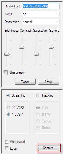
44 7.1.2 Image Control Settings Panel Allow to review and configure various hardware specific (image sensor) settings like: - brightness; - contrast ; - saturation; - gamma; - image orientation; - resolution; - sharpness. Settings can be stored in EEPROM using Save button or can be retrieved from EEPROM using Reset button. NOTE: All changes are real-time and will be stored in SRAM on CTS module. If Save button is not pressed, settings will be lost after restart of CTS Tracking Settings Panel Various modes are accessible for Tracking or Streaming through CTS Client and can be controlled using this panel: - Capture a frame in YUV422 format; - Capture a frame in YUV211 format; - Capture a frame in YUV211 format by initiating a tracking cycle; - Display B&W selected tracking data by initiating a tracking cycle; - Display YUV211 selected tracking data by initiating a tracking cycle; - Display blob bounding boxes at the end of a tracking cycle;

45 Enabling Loop option will initiate a new capture at the end of each frame. Windowed will configure CTS to capture a windowed image of 128 x 120 in QQVGA mode or 256 x 240 in QVGA mode, increasing the speed by 15%.

46 7.1.4 Image Review Panel Used to display the capture image and also to select and review each Color Tracking Class. When enable Preview option, mouse- over and left- click/right- click can be used to select/deselect and review the selection in real- time: Color Tracking Selection Panel For a complete control on the Tracking Color Class selection, a dedicated panel is available that allow a better control for each Tracking Color Class definition and also to communicate with CTS module to retrieve, update and store this information.


47 While this will allow a granular control of the color selection, using the Preview Panel for color selection is recommended.
48 How the buttons can be used: - Clear is to clear existing selection only for current color class; - Download is used to retrieve Tracking Color Class information from CTS (SRAM data); - Upload is used to push the information from CTS Client to CTS module, data will be stored in RAM. Initiating a tracking with debug option enabled can be used for checking; - Store is used to copy the data from SRAM to EEPROM Status Bar Some information will be available on the Status bar: Information displayed here: - connection information (e.g.: Connected, Disconnected, Timeout, etc); - CTS firmware version and MCU installed on the board; - progress bar for data communication (e.g.: image transfer, etc).
49 8 Data format Date returned by CTS module can be in plain text of binary format, depends on the command sent, for images and blob information. This section will provide details regarding data format for every type of package. 8.1 Images In both tracking and frame dumping/streaming modes, CTS may return an image as part of the response. The following sections will cover data formats used by CTS when an image is returned. For technical reasons, camera sensor is configured to capture images in YUV422 format and the entire processing in CTS is done on YUV channels. The formula to convert from YUV to RGB used for displaying the data in RGB format is, as provided by OmniVision: R = Y * (V - 128); G = Y * (U - 128) - ( * (V - 128)); B = Y * (U - 128); NOTE: for more details, please do consult OminVision datasheet for the camera used (e.g.: OV7725 or OV7670) YUV422 packet The packet consists in a header of three bytes, image data in YUV format with 1 byte per channel and a control header of 2 bytes: Byte1: Byte2: Byte3:... Byte(3+((0 to n)*4)+0): Byte(3+((0 to n)*4)+1): Byte(3+((0 to n)*4)+2): Byte(3+((0 to n)*4)+3):... Byte(3+n*4+4): Byte(3+n*4+5): Start byte (0x54) Control byte (0x00) Frame details (see details) Y U Y1 V End byte (0x00) End byte (0xFF) Where: - Frame details is calculated as: o Fist 4 bits will define frame resolution: Bit 4 is 1 for QVGA; Bit 5 is 1 for QQVGA; o Last 4 bits will define image details: Bit 2 is 1 for YUV422 (2 bytes / pixel); Bit 1 is 1 for YUV211 (1 byte per pixel); Bit 0 is 1 for B&W (4 bit per pixel). - n represents the number of pixels in the entire frame divided by 2.

: Byte(3+n*2+4): Start byte (0x54) Control byte (0x00) Frame details (see details) Y U Y1 V End byte (0x00) End byte (0xFF) Where: - Frame details is calculated as: o Fist 4 bits will")
50 For example, the package for a QVGA, YUV422 frame will look like: YUV211 packet The packet consists in a header of three bytes, image data in YUV format with 4 bits per channel and a control header of 2 bytes: Byte1: Byte2: Byte3:... Byte(3+((0 to n)*2)+0): Byte(3+((0 to n)*2)+1):... Byte(3+n*2+3): Byte(3+n*2+4): Start byte (0x54) Control byte (0x00) Frame details (see details) Y U Y1 V End byte (0x00) End byte (0xFF) Where: - Frame details is calculated as: o Fist 4 bits will define frame resolution: Bit 4 is 1 for QVGA; Bit 5 is 1 for QQVGA; o Last 4 bits will define image details: Bit 2 is 1 for YUV422 (2 bytes / pixel); Bit 1 is 1 for YUV211 (1 byte per pixel); Bit 0 is 1 for B&W (4 bit per pixel). - n represents the number of pixels in the entire frame divided by 2. For example, the package for a QVGA, YU211 frame will look like:
):.")
51 8.1.3 B&W packet The packet consists in a header of three bytes, image data in Black and White (B&W) format with 4 bits per pixel and a control header of 2 bytes: Byte1: Byte2: Byte3:... Byte(3+(0 to n)):... Byte(3+n+3): Byte(3+n+4): Start byte (0x54) Control byte (0x00) Frame details (see details) Y Y1 End byte (0x00) End byte (0xFF) Where: - Frame details is calculated as: o Fist 4 bits will define frame resolution: Bit 4 is 1 for QVGA; Bit 5 is 1 for QQVGA; o Last 4 bits will define image details: Bit 2 is 1 for YUV422 (2 bytes / pixel); Bit 1 is 1 for YUV211 (1 byte per pixel); Bit 0 is 1 for B&W (4 bit per pixel). - n represents the number of pixels in the entire frame divided by 2. For example, the package for a QVGA, B&W frame will look like: 8.2 Blob details Blob details are only available in Tracking mode. In this mode, CTS, can return either a package that contains blob details or a package that contains an image and a package that contains blob details after that. In the sections bellow, only blob details packages in binary format will be explained. NOTE: This information is already available in Chapter 6.
52 8.2.1 Tracking Multiple blobs Blob details for multiple blobs are returned in following format if at least one blob of predefined colors is detected with weight over 1%: Byte1: Start byte (0x42) Byte2: Start byte (0x00) Byte3: Number of blobs detected(n)... Byte(4+((0 to n)*15)+0): Blob ID Byte(4+((0 to n)*15)+1): COG X MSB Byte(4+((0 to n)*15)+2): COG X LSB Byte(4+((0 to n)*15)+3): COG Y MSB Byte(4+((0 to n)*15)+4): COG Y LSB Byte(4+((0 to n)*15)+5): COG Y MSB Byte(4+((0 to n)*15)+6): Weight in percentage Byte(4+((0 to n)*15)+7): Top X MSB Byte(4+((0 to n)*15)+8): Top X LSB Byte(4+((0 to n)*15)+9): Top Y MSB Byte(4+((0 to n)*15)+10): Top Y LSB Byte(4+((0 to n)*15)+11): Bottom X MSB Byte(4+((0 to n)*15)+12): Bottom X LSB Byte(4+((0 to n)*15)+13): Bottom Y MSB Byte(4+((0 to n)*15)+14): Bottom Y LSB... Byte(4+n*15+15): End byte (0x00) Byte(4+n*15+16): End byte (0xFF) Tracking one blob In Fast Tracking mode CTS will return basic tracking details in following format if a blob of predefined color is detected with weight over 1%: Byte1: Byte2: Byte3: Byte4: Byte5: Byte6: Byte7: Byte8: Byte9: Start byte (0x42) Start byte (0x00) COG X MSB COG X LSB COG Y MSB COG Y LSB Weight (in percentage) End byte (0x00) End byte (0xFF) No blobs detected If no blob detected or weight bellow 1%, the data returned have the following format: Byte1: Byte2: Byte3: Start byte (0x42) Start byte (0x00) 0x00
53 Byte4: Byte5: End byte (0x00) End byte (0xFF)
54 9 Configuring CTS module CTS modules can be configured either using command line or using CTS Client. Bellow is a short how to on how to do this. Both modes require a TTL serial connection to a PC. NOTE: - CTS boards only work with UART TTL adapters with maximum 5 volts (e.g.: FTDI) any other adapters will damage the board! - By default CTS boards will come configured to work at baud, however, if speed changed and stored in EEPROM proper speed need to be used. - Only predefined values can be used, however, all values are standard. 9.1 Configuration using command line Once connected to a CTS board using any available terminal client (e.g.: Putty, CoolTerm, HyperTerminal, etc.) you should be able to see a similar message like the one bellow when reset the module: camera tracking system Version: 0521d644 OK Else, you can just type v? and you should be able to see something like: Version: 0521d644 If is not working, please do check the connectivity and the speed before proceed to the next step Changing serial speed Current serial speed can only be changed through command line, this can not be done using CTS Client to avoid accidental change. Connect to the CTS module and check if is working by checking current serial speed using u?, you should see something like: UART speed: 115,200 To check which options are available, use ul : 0-38, , , , , ,600
55 To change the speed to baud type u5. Once this done, CTS will switch automatically to baud, however, this setting will only be store if will be updated in EEPROM. For this, close the terminal window and open another one using the selected speed ( baud in this case). Check if can communicate with CTS by running either v? or u?. If you can see the text returned correctly you can then store the new settings in EEPROM by running Mw. To check, reset the module and you should see again something like: camera tracking system Version: 0521d644 OK Changing Image settings For this the commands are explained in Chapter 5. First, check existing settings either by listing all settings with M? : Version: 0521d644 Camera model: OV7721 Vendor ID: 7F.A2 UART speed: 115,200 Resolution: QQVGA (160 x 120) AWB: on Brightness: +25% Contrast: 0 % Saturation: 0 % Gamma: -25% Orientation: flip + mirror Sharpness: enabled To configure CTS module for -1 brightness, +1 contrast, -1 saturation, +1 gamma, disable sharpness, normal orientation and QVGA resolution we can issue the following commands: b3 c5 s3 g5 Sd fn r0 Then check the configuration again by sending M? : Version: 0521d644 Camera model: OV7721
56 Vendor ID: 7F.A2 UART speed: 115,200 Resolution: QVGA (320 x 240) AWB: on Brightness: -25% Contrast: +25% Saturation: -25% Gamma: +25% Orientation: normal Sharpness: disabled If is correct, just save the configuration using Mw Changing Tracking Color Class Changing Tracking Color Class definition can be done using command line, however, using CTS client may be more convenient. First, list existing data in SRAM by running Cr, you should see something like: SRAM C C D F F A A This will be easier if translated to a binary representation as each bit represent a color ID for each channel. Data can be modified line by line, however, the line number have to be provided in HEX format (ASCII HEX) like: Cs0A0F0031 Which means to change the values for line 10 with for Y, for U and for V.
57 Once all changes are completed, can check again using Cr : SRAM C C D F F A A Then can store in EEPROM using Cw or can revert to existing values in EEPROM by using Cc Training mode Training mode is available through command-line and offer an easy alternative to learn a color class without a need of using CTS Client. In Training mode, by default, CTS will capture a snapshot of half of the current selected resolution and populate the color class map with the unique colors within the snapshot. It will be advisable to first define a smaller for the training box, let s say of 40 pixels width and 30 pixels height (details have to be in HEX format): Lb281e To save the new value to EEPROM use: Lw Choose an available class definition index (e.g.: 1) and trigger a learning process: LC1 This will return something like: Color class details:
58 Or can use: Lc1 In this case will only return a confirmation: OK The class definition will become available right away and can be used for tracking. 9.2 Configuration using CTS Client CTS Client is actually only a wrapper communicating with the CTS module issuing same commands described before. However, since can see the results by capturing a frame directly do provide a more convenient way of configuring CTS module Change image settings Changing image settings is pretty simple: - connect to CTS: - capture a test image:

59 - review: - change settings:

60 - capture: - review:

61 And keep repeating this till you get the results you want then save to EEPROM:

62 9.2.2 Change Tracking Color Class settings One of the most important features is the ability to create or edit Tracking Color Class table by using the visual interface in CTS Client. Once the module is configured for optimal performance in the respective environment (saturation, gamma, white balance, etc.), in Tracking mode, we select YUV and capture a frame that contains the information we want to use to calibrate/fine- tune the Color Class Table: Enable Preview if not already enabled: Choose a color class to store the new definitions:

63 Move mouse over the Image Review panel and left- click over the color you want to add to the class definition:

64 Keep selecting different shades of the respective color until you get the result you want: Change the color class to add a new set of definitions:

65 Select new definitions following same steps like before: Once all classes are defined can upload the settings from CTS Client to CTS module. Data will be stored in SRAM only for now:
66 To move the settings to EEPROM:
67 9.2.3 Training mode To use Training mode using CTS Client, first capture a test frame after you position the object with the color class you want to learn, in front of the camera and confirm is in the middle of the image in Tracking mode: Select the color index where the new definitions should be stored, confirm that the color class you are trying to learn is covering the defined color class training box then click on Train button:

68 For confirm the color class was properly learnt, choose Debug option in Tracking mode and then Capture: In Preview panel you then should be able to see the all the pixels detected using the color classes already defined, including the newly trained color class:

69 If the color class definition is correct for your application can choose to store the new settings in EEPROM using Store.
Serial JPEG Camera Module Data Sheet
 4D SYSTEMS µcam529 Serial JPEG Camera Module Document Date: 15th July 2010 Document Revision: 2.0 2010 4D Systems www.4dsystems.com.au Page 1 of 20 4D SYSTEMS µcam Serial JPEG Camera Module Description
DATASHEET 4D SYSTEMS. Serial JPG Camera Module TURNING TECHNOLOGY INTO ART. Document Date: 5 th September 2012 Document Revision: 1.
 TURNING TECHNOLOGY INTO ART DATASHEET Serial JPG Camera Module Document Date: 5 th September 2012 Document Revision: 1.0 Uncontrolled Copy when printed or downloaded. Please refer to the 4D Systems website
Serial JPEG Camera Module Data Sheet
 4D SYSTEMS µcam Serial JPEG Camera Module Document Date: 18th November 2011 Document Revision: 7.0 2011 4D Systems www.4dsystems.com.au Page 1 of 23 4D SYSTEMS µcam Serial JPEG Camera Module Description
DATASHEET 4D SYSTEMS. 4D Arduino Adaptor Shield TURNING TECHNOLOGY INTO ART. 4Display-Adaptor-Shield
 TURNING TECHNOLOGY INTO ART DATASHEET 4Display-Adaptor-Shield Document Date: 20 th November 2012 Document Revision: 1.0 Uncontrolled Copy when printed or downloaded. Please refer to the 4D Systems website
DATASHEET 4D SYSTEMS. 4D Raspberry Pi Serial Adaptor TURNING TECHNOLOGY INTO ART. 4D-Serial-Pi-Adaptor
 TURNING TECHNOLOGY INTO ART DATASHEET 4D-Serial-Pi-Adaptor Document Date: 20 th November 2012 Document Revision: 1.0 Uncontrolled Copy when printed or downloaded. Please refer to the 4D Systems website
DATASHEET 4D SYSTEMS. 4D Raspberry Pi Serial Adaptor TURNING TECHNOLOGY INTO ART. 4D-Serial-Pi-Adaptor
 DATASHEET TURNING TECHNOLOGY INTO ART 4D Raspberry Pi Serial Adaptor 4D-Serial-Pi-Adaptor Document Date: 4 th September 2013 Document Revision: 1.1 Uncontrolled Copy when printed or downloaded. Please
DATASHEET 4D SYSTEMS. 4D Raspberry Pi Serial Adaptor TURNING TECHNOLOGY INTO ART. 4D-Serial-Pi-Adaptor
 DATASHEET TURNING TECHNOLOGY INTO ART 4D Raspberry Pi Serial Adaptor 4D-Serial-Pi-Adaptor Document Date: 21 st August 2014 Document Revision: 1.2 Uncontrolled Copy when printed or downloaded. Please refer
DATASHEET 4D SYSTEMS TURNING TECHNOLOGY INTO ART. microusb Programming Adaptor. USB to UART Serial Bridge
 TURNING TECHNOLOGY INTO ART DATASHEET microusb Programming Adaptor µusb-pa5 USB to UART Serial Bridge Document Date: 27 th November 2013 Document Revision: 1.1 Uncontrolled Copy when printed or downloaded.
DATASHEET 4D SYSTEMS TURNING TECHNOLOGY INTO ART. USB to Serial UART Bridge Converter. Document Date: 5 th September 2012 Document Revision: 1.
 TURNING TECHNOLOGY INTO ART DATASHEET USB to Serial UART Bridge Converter µusb-mb5 Document Date: 5 th September 2012 Document Revision: 1.0 Uncontrolled Copy when printed or downloaded. Please refer to
DATASHEET 4D SYSTEMS. uusb-pa5 uusb-pa5-ii. microusb Programming Adaptor TURNING TECHNOLOGY INTO ART. USB to UART Serial Bridge
 DATASHEET TURNING TECHNOLOGY INTO ART microusb Programming Adaptor -II USB to UART Serial Bridge Document Date: 17 th July 2015 Document Revision: 2.0 Uncontrolled Copy when printed or downloaded. Please
DATASHEET. 4.3 Embedded SPI Display. 4DLCD-FT843 Powered by the FTDI FT800 Video Engine. Document Date: 25 th September 2013 Document Revision: 0.
 DATASHEET 4.3 Embedded SPI Display 4DLCD-FT843 Powered by the FTDI FT800 Video Engine Document Date: 25 th September 2013 Document Revision: 0.4 Uncontrolled Copy when printed or downloaded. Please refer
Font Tool User Guide. Abstract. Document Date: 1 July 2009 Document Revision: 01
 Document Date: 1 July 2009 Document Revision: 01 Abstract This User guide explains Font Tool software in detail. Font Tool will assist the user in converting Windows fonts (including true type) into the
DATASHEET 4D SYSTEMS. 4Display Shield with 2.2 Display TURNING TECHNOLOGY INTO ART. 4Display-Shield-22
 TURNING TECHNOLOGY INTO ART DATASHEET 4Display Shield with 2.2 Display Document Date: 31 st October 2012 Document Revision: 1.1 Uncontrolled Copy when printed or downloaded. Please refer to the 4D Systems
DATASHEET. Serial Camera Module. ucam-ii. Document Date: 24 th July 2014 Document Revision: 1.3
 DATASHEET Serial Camera Module ucam-ii Document Date: 24 th July 2014 Document Revision: 1.3 Uncontrolled Copy when printed or downloaded. Please refer to the 4D Systems website for the latest Revision
DATASHEET. Serial Camera Module. ucam-ii. Document Date: 6 th March 2014 Document Revision: 1.1
 DATASHEET Serial Camera Module ucam-ii Document Date: 6 th March 2014 Document Revision: 1.1 Uncontrolled Copy when printed or downloaded. Please refer to the 4D Systems website for the latest Revision
DATASHEET. 4D 4.3 LCD CAPE Beagle Bone Black 4.3 LCD CAPE. Document Date: 3 rd February 2014 Document Revision: 1.9
 DATASHEET 4D 4.3 LCD CAPE Beagle Bone Black 4.3 LCD CAPE Document Date: 3 rd February 2014 Document Revision: 1.9 Uncontrolled Copy when printed or downloaded. Please refer to the 4D Systems website for
udrive-usd-g1 Embedded DOS micro-drive Module Data Sheet
 4D SYSTEMS udrive-usd-g1 Embedded DOS micro-drive Module Document Date: 4 rh November 2011 Document Revision: 4.0 Note: This revision of the Dcoument applies to udrive PmmC Rev23 or above. 2011 4D Systems
DATASHEET 4D SYSTEMS TURNING TECHNOLOGY INTO ART. Embedded DOS micro-drive Module. μdrive-μsd-g1
 TURNING TECHNOLOGY INTO ART DATASHEET Embedded DOS micro-drive Module μdrive-μsd-g1 Document Date: 11 th September 2012 Document Revision: 1.1 Uncontrolled Copy when printed or downloaded. Please refer
DATASHEET 4D SYSTEMS TURNING TECHNOLOGY INTO ART. Carrier Board for μoled-160-g1/g2 CB-160-G1
 TURNING TECHNOLOGY INTO ART DATASHEET Carrier Board for μoled-160-g1/g2 Document Date: 21 st September 2012 Document Revision: 1.0 Uncontrolled Copy when printed or downloaded. Please refer to the 4D Systems
HMC1022 Digital Compass
 Key Features Based on Honeywell s HMC1022 solid-state magnetic sensor Choice of 2 Interface Options (UART/I2C) Standard Pin Headers come soldered Plug and Play Module SPECIFICATIONs Angular Measuring Range
Workshop 4 Installation INSTALL GUIDE. Document Date: February 4 th, Document Revision: 1.1
 INSTALL GUIDE Workshop 4 Installation Document Date: February 4 th, 2013 Document Revision: 1.1 Description This document describes how to install and configure Workshop 4, and how to install the driver
DATASHEET 4D SYSTEMS. Embedded Audio-Sound Module TURNING TECHNOLOGY INTO ART SOMO-14D. Document Date: 5 th February 2013 Document Revision: 1.
 DATASHEET TURNING TECHNOLOGY INTO ART Embedded Audio-Sound Module Document Date: 5 th February 2013 Document Revision: 1.1 Uncontrolled Copy when printed or downloaded. Please refer to the 4D Systems website
QT3 Xplained Pro. Preface. Atmel QTouch USER GUIDE
 Atmel QTouch QT3 Xplained Pro USER GUIDE Preface The Atmel QT3 Xplained Pro is an extension board, which enables the evaluation of a capacitive touch 12 key numpad in mutual capacitance configuration.
DATASHEET. gen4 Programming Adaptor For all gen4 sizes (Picaso and Diablo16) gen4-pa. Document Date: 29 th January 2016 Document Revision: 1.
 gen4-pa. Document Date: 29 th January 2016 Document Revision: 1.") For all gen4 sizes (Picaso and Diablo16) DATASHEET Document Date: 29 th January 2016 Document Revision: 1.0 Uncontrolled Copy when printed or downloaded. Please refer to the 4D Systems website for the
For all gen4 sizes (Picaso and Diablo16) DATASHEET Document Date: 29 th January 2016 Document Revision: 1.0 Uncontrolled Copy when printed or downloaded. Please refer to the 4D Systems website for the
Introduction. Rev.1.2
 Introduction The Revelation board is an evaluation tool which is designed to help to start working with Riverdi TFT panels with FT8XX controllers. It can also be used as a platform to build your own application.
DATASHEET. 4.3 Embedded SPI Display. 4DLCD-FT843 Powered by the FTDI FT800 Video Engine. Document Date: 8 th January 2014 Document Revision: 1.
 DATASHEET 4.3 Embedded SPI Display 4DLCD-FT843 Powered by the FTDI FT800 Video Engine Document Date: 8 th January 2014 Document Revision: 1.2 Uncontrolled Copy when printed or downloaded. Please refer
4D Systems. Application Note: 4D-AN-G3001. in ViSi Environment. Document Date: 15 th December Document Revision: 1.0
 4D Systems Application Note: Displaying an Image on GOLDELOX Modules in ViSi Environment Document Date: 15 th December 2012 Document Revision: 1.0 2012 4D Systems www.4dsystems.com.au Page 1 of 8 Description
USER GUIDE. Atmel QT1 Xplained Pro. Preface
 USER GUIDE Atmel QT1 Xplained Pro Preface Atmel QT1 Xplained Pro kit is an extension board that enables evaluation of self- and mutual capacitance mode using the Peripheral Touch Controller (PTC) module.
Ethernet1 Xplained Pro
 Ethernet1 Xplained Pro Part Number: ATETHERNET1-XPRO The Atmel Ethernet1 Xplained Pro is an extension board to the Atmel Xplained Pro evaluation platform. The board enables the user to experiment with
0.3 Mega Pixels Serial JPEG Camera with NTSC Video
 SC03MPD: 0.3 Mega Pixels Serial JPEG Camera User Manual 0.3 Mega Pixels Serial JPEG Camera with NTSC Video SC03MPD User Manual, Rev. D For latest user manual, please visit: www.jpegcamera.com Introduction
February 28,
 February 28, 2014 1 http://www.mattairtech.com/ Table of Contents Overview...3 Introduction...3 Features...4 Hardware...5 Main Header Pins...5 ISP Header Pins...6 Solder Jumpers...6 Onboard 3.3V, 250mA
SBAT90USB162 Atmel. SBAT90USB162 Development Board User s Manual
 SBAT90USB162 Atmel AT90USB162 Development Board User s manual 1 1. INTRODUCTION Thank you for choosing the SBAT90USB162 Atmel AT90USB162 development board. This board is designed to give a quick and cost-effective
DATASHEET. 3.2 Display Bezel. 4D-Bezel-32 For the ulcd-32ptu Display Module. Document Date: 16 th September 2013 Document Revision: 1.
 DATASHEET 3.2 Display Bezel 4D-Bezel-32 For the ulcd-32ptu Display Module Document Date: 16 th September 2013 Document Revision: 1.0 Uncontrolled Copy when printed or downloaded. Please refer to the 4D
The SC03MPA camera is capable of outputting JPEG format images and PAL/NTSC video (Video is available only per request).
.") SC03MPA: 0.3 Mega Pixels Serial JPEG Camera User Manual 0.3 Mega Pixels Serial JPEG Camera SC03MPA User Manual, Rev. D (2018) For latest user manual, please visit: Introduction The SC03MPA Camera is a
SC03MPA: 0.3 Mega Pixels Serial JPEG Camera User Manual 0.3 Mega Pixels Serial JPEG Camera SC03MPA User Manual, Rev. D (2018) For latest user manual, please visit: Introduction The SC03MPA Camera is a
USER GUIDE. Atmel QT6 Xplained Pro. Preface
 USER GUIDE Atmel QT6 Xplained Pro Preface Atmel QT6 Xplained Pro kit is a Xplained Pro extension board that enables the evaluation of a mutual capacitance touch suface using the Peripheral Touch Controller
USER GUIDE. ATWINC1500 Xplained Pro. Preface
 USER GUIDE ATWINC1500 Xplained Pro Preface Atmel ATWINC1500 Xplained Pro is an extension board to the Atmel Xplained Pro evaluation platform. The extension board allows to evaluate the Atmel ATWINC1510/1500
LBAT90USB162 Atmel. LBAT90USB162 Development Board User s Manual
 LBAT90USB162 Atmel AT90USB162 Development Board User s manual 1 1. INTRODUCTION Thank you for choosing the LBAT90USB162 Atmel AT90USB162 development board. This board is designed to give quick and cost-effective
USER GUIDE. Atmel OLED1 Xplained Pro. Preface
 USER GUIDE Atmel OLED1 Xplained Pro Preface Atmel OLED1 Xplained Pro is an extension board to the Atmel Xplained Pro evaluation platform. The board enables the user to experiment with user interface applications
SC03MPC: 0.3 Mega Pixels Serial JPEG Camera Infrared User Manual. Introduction
 0.3 Mega Pixels Serial JPEG Camera Infrared SC03MPC User Manual, Rev. C For latest user manual, please visit: Introduction The SC03MPC Camera is a highly integrated serial JPEG camera module which can
USERS MANUAL. 4D Systems. (4DGL Platform Only) Revision 1.0
 Revision 1.0") µoled-3202x-p1 USERS MANUAL (4DGL Platform Only) Revision 1.0 4D Systems Table of contents 1. Introduction 3 2. Features 4 3. Circuit Diagram 6 4. User Interface Pin Description 9 5. Expansion Ports Pin
µoled-3202x-p1 USERS MANUAL (4DGL Platform Only) Revision 1.0 4D Systems Table of contents 1. Introduction 3 2. Features 4 3. Circuit Diagram 6 4. User Interface Pin Description 9 5. Expansion Ports Pin
C1098 JPEG Module User Manual
 C1098 JPEG Module User Manual General Description C1098 is VGA camera module performs as a JPEG compressed still camera that can be attached to a wireless or PDA host. Users can send out a snapshot command
4D SYSTEMS TURNING TECHNOLOGY INTO ART. Application Note: 4D-AN-G5002
 TURNING TECHNOLOGY INTO ART APPLICATION NOTE Application Note: Displaying an Image, Video or Animation on the Goldelox Modules in Serial Environment Document Date: 25 th February 2013 Document Revision:
2.8 microlcd Intelligent PICASO Display Module
 Product Brief 2.8 microlcd Intelligent PICASO Display Module µlcd-28ptu www.4dsystems.com.au Rev 1.2 MESSAGE FROM THE CEO To our valued customers, Thank you for your interest in 4D Systems and the products
C628 Enhanced JPEG Module. User Manual
 C628 Enhanced JPEG User Manual v1.1 Release Note: 1. May 2, 2006 official released v1.0 2. Dec 27, 2006 revise electrical characteristics Table of Contents Part I - Hardware Overview 1 Features.. 1 Specifications
Application Note: 4D-AN-P4010 ViSi-Genie Connection to a Host with Red- Green-Blue LED Control
 APPLICATION NOTE Application Note: ViSi-Genie Connection to a Host with Red- Green-Blue LED Control Document Date: January 3 rd, 2013 Document Revision: 1.1 The RGB LED is a classic 5 mm with four pins:
4D Systems. Application Note: 4D-AN-P2002. Playing Video on PICASO based modules using RAW option. Document Date: 15 th December 2012
 4D Systems Application Note: Playing Video on PICASO based modules using RAW option Document Date: 15 th December 2012 Document Revision: 1.0 2012 4D Systems www.4dsystems.com.au Page 1 of 8 Description
APPLICATION NOTE. Application Note: 4D-AN-P4007. ViSi-Genie Play Video. Document Date: November 15 th, Document Revision: 1.
 APPLICATION NOTE Application Note: ViSi-Genie Play Video Document Date: November 15 th, 2012 Document Revision: 1.0 Description This Application Note explores the possibilities provided by ViSi-Genie for
APPLICATION NOTE. Application Note: 4D-AN-P4004. ViSi-Genie Advanced Buttons. Document Date: November 15 th, Document Revision: 1.
 APPLICATION NOTE Application Note: ViSi-Genie Advanced Buttons Document Date: November 15 th, 2012 Document Revision: 1.0 Description This Application Note explores the possibilities provided by ViSi-Genie
QT2 Xplained Pro. Preface. Atmel QTouch USER GUIDE
 Atmel QTouch QT2 Xplained Pro USER GUIDE Preface Atmel QT2 Xplained Pro kit is an extension board that enables the evaluation of a mutual capacitance touch surface using the Peripheral Touch Controller
APPLICATION NOTE. Application Note: 4D-AN-P4009. ViSi-Genie Inputs. Document Date: November 19 th, Document Revision: 1.0
 APPLICATION NOTE Application Note: ViSi-Genie Inputs Document Date: November 19 th, 2012 Document Revision: 1.0 Description This Application Note explores the possibilities provided by ViSi-Genie for the
GW-USB-06. User s Guide. IQRF USB Gateway. FW v MICRORISC s.r.o. User_Guide_GW-USB-06_ Page 1
 FW v1.04 IQRF USB Gateway User s Guide 2016 MICRORISC s.r.o. www.iqrf.org User_Guide_GW-USB-06_160122 Page 1 Description GW-USB-06 is an IQRF gateway with USB connectivity. It is intended as an interface
LPC2148 DEV BOARD. User Manual.
 LPC2148 DEV BOARD User Manual www.coineltech.com www.coineltech.com Designed by CoiNel Technology Solutions LLP No-816, 2 nd Floor, 4 th B Cross, 9 th A Main, RPC Layout, Vijaynagar, Bangalore-560040 State:
ED1021 I/O Expander with UART interface & analog inputs
 Preliminary Highlights 2.7V 5V power supply range. 12 GPIOs. Up to 40mA maximum current in each output except GPIO8 (up to a total device current of 175mA). Most GPIOs can be an input to a 10bit ADC. Simple
F2MC MB90385 series Evaluation Board Documentation. Revision Date Comment V New document
 F2MC MB90385 series Evaluation Board Documentation Revision Date Comment V1.0 08.25.02 New document 1 Warranty and Disclaimer To the maximum extent permitted by applicable law, Fujitsu Microelectronics
USER GUIDE EDBG. Description
 USER GUIDE EDBG Description The Atmel Embedded Debugger (EDBG) is an onboard debugger for integration into development kits with Atmel MCUs. In addition to programming and debugging support through Atmel
USER GUIDE. Atmel maxtouch Xplained Pro. Preface
 USER GUIDE Atmel maxtouch Xplained Pro Preface Atmel maxtouch Xplained Pro is an extension board to the Atmel Xplained Pro evaluation platform. The board enables the user to experiment with user interface
F²MC-8L FAMILY MB89201 SERIES FLASH PROGRAMMING 8-BIT MICROCONTROLLER APPLICATION NOTE. Fujitsu Microelectronics Europe Application Note
 Fujitsu Microelectronics Europe Application Note MCU-AN-300001-E-V10 F²MC-8L FAMILY 8-BIT MICROCONTROLLER MB89201 SERIES FLASH PROGRAMMING APPLICATION NOTE Revision History Revision History Date 2005-02-09
*X13186* Multimedia and Control Networking Technology. MOST Media Oriented Systems Transport. MediaLB Analyzer Hardware Manual
 Multimedia and Control Networking Technology MediaLB Analyzer MediaLB Monitor USB V1.0.1 3-pin Active-Pod Low Speed V1.0.1 6-pin Active-Pod High Speed V1.0.0 Document Information Version: V2.0.X-2 Date:
ArduCAM-M-5MP Camera Shield
 ArduCAM-M-5MP Camera Shield 5MP SPI Camera User Guide Rev 1.0, Mar 2015 Table of Contents 1 Introduction... 2 2 Application... 2 3 Features... 3 4 Key Specifications... 3 5 Pin Definition... 3 6 Block
4D SYSTEMS APPLICATION NOTE. Application Note: 4D-AN-G5001 TURNING TECHNOLOGY INTO ART. Serial - Displaying Third-Party Fonts
 APPLICATION NOTE 4D SYSTEMS TURNING TECHNOLOGY INTO ART Application Note: Serial - Displaying Third-Party Fonts Document Date: 5th February 2013 Document Revision: 1.0 Description This application note
APPLICATION NOTE. Atmel QT4 Xplained Pro User Guide ATAN0114. Preface
 APPLICATION NOTE Atmel QT4 Xplained Pro User Guide ATAN0114 Preface Atmel QT4 Xplained Pro kit is an extension board that enables evaluation of self-capacitance mode proximity and touch using the peripheral
EDBG. Description. Programmers and Debuggers USER GUIDE
 Programmers and Debuggers EDBG USER GUIDE Description The Atmel Embedded Debugger (EDBG) is an onboard debugger for integration into development kits with Atmel MCUs. In addition to programming and debugging
USER GUIDE. Workshop 4 User Guide. Document Date: 17 th December 2012 Document Revision: 1.1
 USER GUIDE Workshop 4 User Guide Document Date: 17 th December 2012 Document Revision: 1.1 Uncontrolled Copy when printed or downloaded. Please refer to the 4D Systems website for the latest Revision of
AN10955 Full-duplex software UART for LPC111x and LPC13xx
 Rev. 1 13 July 2010 Application note Document information Info Content Keywords LPC111X, LPC13XX, UART, software Abstract This application note illustrates how software running on an LPC111X or LPC13XX
C6820 Enhanced JPEG Module. User Manual V2.0. Release Note: 1. Feb 8, 2007 official released v Nov 16, 2007 released V2.0
 C6820 Enhanced JPEG User Manual V2.0 Release Note: 1. Feb 8, 2007 official released v1.0 2. Nov 16, 2007 released V2.0 Table of Contents C6820 Enhanced JPEG Part I - Hardware Overview... 3 Features...3
QBridge. I2C, SPI, CAN Control Software User s Manual. Date: Rev 1.3
 QBridge I2C, SPI, CAN Control Software User s Manual Date: 9-10-2005 Rev 1.3 1. Introduction...1 1.1. What QBridge can do?... 1 1.2. Disclaimer... 1 1.3. Operational Format... 1 1.4. QBridge-V2... 1 2.
EVB-USB2640 Evaluation Board Revision A
 Copyright 2008 SMSC or its subsidiaries. All rights reserved. Circuit diagrams and other information relating to SMSC products are included as a means of illustrating typical applications. Consequently,
Wasp Embedded Controller
 Wasp Embedded Controller Wasp16/32/64 Hardware Reference Guide PCB Rev 1.0 WASP16 WASP32 WASP64 MC433 Hardware Reference Guide Manual Revision 0.85 Table of Contents Warranty Statement...2 1.0 Introduction....4
PIC-P28-USB development board Users Manual
 PIC-P28-USB development board Users Manual Rev.A, June 2007 Copyright(c) 2007, OLIMEX Ltd, All rights reserved INTRODUCTION: PIC-P28-USB board was designed in mind to create board which to allow easy interface
SOMO-14D Embedded Audio-Sound Module
 4D SYSTEMS SOMO-14D Embedded Audio-Sound Module Document Date: 24th November 2009 Document Revision: 3.0 2009 4D Systems www.4dsystems.com.au Page 1 of 13 4D SYSTEMS SOMO-14D Embedded Audio Module Description
USER GUIDE. Atmel Segment LCD1 Xplained Pro. Preface
 USER GUIDE Atmel Segment LCD1 Xplained Pro Preface Atmel Segment LCD1 Xplained Pro is an extension board to the Atmel Xplained Pro evaluation platform. Segment LCD1 Xplained Pro is designed to kick-start
SC20MPC: 2 Mega Pixels Serial JPEG Camera User Manual. Introduction
 2 Mega Pixels Serial JPEG Camera SC20MPC User Manual, Rev. F (August 2018) For latest user manual, please visit: Introduction The SC20MPC Camera is a highly integrated serial JPEG camera module which can
ATtiny104 Xplained Nano. Preface. AVR 8-bit Microcontrollers USER GUIDE
 AVR 8-bit Microcontrollers ATtiny104 Xplained Nano USER GUIDE Preface The Atmel ATtiny104 Xplained Nano evaluation kit is a hardware platform to evaluate the ATtiny104 microcontroller. Supported by the
NeoLoch. Inquisitor 4116 DRAM Blade Manual. Overview. Preliminary Release
 NeoLoch Inquisitor 4116 DRAM Blade Manual Overview The Inquisitor 4116 DRAM blade is designed to test 16 pin DRAM ICs. Current tests include 4116, 9016, D416, 4027 and 4096. The Inquisitor 4116 DRAM tester
JP2380 Sensor Module. JP Sensor. Features: MCU Embedded. Specifications. Sensor with total solution
 JP Sensor Sensor with total solution JP2380 is an ultra-thin CMOS fingerprint sensor combined with MCU which can be widely applied in smart card since it is neat and compact. Cermet-like coating provides
LCD-1 Peripheral Board Technical Manual
 LCD-1 Peripheral Board Technical Manual Document Revision: 1.03 Date: 22 April, 2003 BiPOM Electronics, Inc. 16301 Blue Ridge Road, Missouri City, Texas 77489 Telephone: 1-713-283-9970. Fax: Fax: 1-281-416-2806
C329-SPI User Manual. Release Note: V th September, 2010 First release. V th January 2012 Second release. C329-SPI User Manual
 C329-SPI User Manual Release Note: V1.0 27 th September, 2010 First release V1.1 12 th January 2012 Second release C329-SPI JPEG Compression Module 1 2010.08.25 General The C329 is a colour VGA camera
USB2507. Integrated USB 2.0 Compatible 7-Port Hub PRODUCT FEATURES. Data Brief
 USB2507 Integrated USB 2.0 Compatible 7-Port Hub PRODUCT FEATURES Data Brief Integrated USB 2.0 Compatible 7-Port Hub 7 Transaction Translators for highest performance High-Speed (480Mbits/s), Full-Speed
EVB-USB2250 User Manual Revision B
 Copyright 2009 SMSC or its subsidiaries. All rights reserved. Circuit diagrams and other information relating to SMSC products are included as a means of illustrating typical applications. Consequently,
Table 1. RS232 Serial Adapter DEBUG Connector Pin Descriptions
 RS232 SERIAL ADAPTER (EC2) USER S GUIDE 1. Contents The RS232 Serial Adapter (EC2) package contains the following items: RS232 Serial Adapter (RS232 to Debug Interface) 7 Ribbon Cable 2. RS232 Serial Adapter
4D SYSTEMS APPLICATION NOTE. Application Note: 4D-AN-P3001 TURNING TECHNOLOGY INTO ART. ViSi - Displaying Third-Party Fonts
 TURNING TECHNOLOGY INTO ART APPLICATION NOTE Application Note: 4D-AN-P3001 ViSi - Displaying Third-Party Fonts Document Date: 15th March 2013 Document Revision: 1.0 Description This Application Note explains
AKKON USB CONTROLLER BOARD
 TN002 AKKON USB CONTROLLER BOARD USB Microcontroller board with the PIC18F4550 * Datasheet Authors: Gerhard Burger Version: 1.0 Last update: 20.01.2006 File: Attachments: no attachments Table of versions
GigE Area Scan Camera
 GigE Area Scan Camera Quick Start Guide V1.0.0 ZHEJIANG DAHUA TECHNOLOGY CO.LDT Overview Abstract This manual described GigE Area Scan Camera, including product introduction, Structure, basic parameters
I/O1 Xplained Pro. Preface. Atmel MCUs USER GUIDE
 Atmel MCUs I/O1 Xplained Pro USER GUIDE Preface Atmel I/O1 Xplained Pro is an extension board to the Atmel Xplained Pro evaluation platform. I/O1 Xplained Pro is designed to give a wide variety of functionality
DATASHEET. 4D 7.0 LCD CAPE Beagle Bone Black 7.0 LCD CAPE. Document Date: 3 rd February 2014 Document Revision: 1.2
 DATASHEET 4D 7.0 LCD CAPE Beagle Bone Black 7.0 LCD CAPE Document Date: 3 rd February 2014 Document Revision: 1.2 Uncontrolled Copy when printed or downloaded. Please refer to the 4D Systems website for
Smart RF Device Family - Getting Started Guide. Features. Description. References ATAN0115 APPLICATION NOTE
 ATAN0115 Smart RF Device Family - Getting Started Guide APPLICATION NOTE Features Introduction to the Smart RF device family, including ATA82xx receivers, the ATA8520 transmitter and ATA85xx transceivers
RFID: Read and Display V2010. Version 1.1. Sept Cytron Technologies Sdn. Bhd.
 PR8-B RFID: Read and Display V2010 Version 1.1 Sept 2010 Cytron Technologies Sdn. Bhd. Information contained in this publication regarding device applications and the like is intended through suggestion
DATASHEET. MK-070C-HP High Performance 7 Inch Capacitive Touch Display. Amulet. Technologies. July 2015 Revision A
 High Performance 7 Inch Capacitive Touch Display DATASHEET July 2015 Revision A Introduction The MK-070C is the newest family member in the Display Module product line. The new 7 Capacitive Display Module
4D SYSTEMS µoled-160-g1(sgc) Serial OLED Display Module Data Sheet
 Serial OLED Display Module Data Sheet") 4D SYSTEMS Serial OLED Display Module Document Date: 22nd August 2009 Document Revision: 2.0 Page 1 of 13 Serial OLED Display Module 4D SYSTEMS Description Features The uoled-160-g1(sgc) is a compact and
4D SYSTEMS Serial OLED Display Module Document Date: 22nd August 2009 Document Revision: 2.0 Page 1 of 13 Serial OLED Display Module 4D SYSTEMS Description Features The uoled-160-g1(sgc) is a compact and
BrewTroller Phoenix. Owners Manual. Updated - March 14, 2016 BREWTROLLER PHOENIX 1
 BrewTroller Phoenix Owners Manual Updated - March 14, 2016 BREWTROLLER PHOENIX 1 2016 BrewTroller All Rights Reserved. Product warranty or service will not be extended if: (1) the product is repaired,
NORITAKE ITRON VFD MODULES GU192x16H-K612C5
 192 x 16 High Brightness Dot Graphic Display Single 12V DC Supply 2 ASCII Fonts (5 x 7 and 10 x 14) RS232 Asynchronous Serial Interface 31 Selectable Multi Drop Addresses Transformerless PSU (patent pending)
Dual Serial Shield User Manual
 Dual Serial Shield User Manual PN: 2050 Berkshire Products, Inc. Phone: 770-271-0088 http://www.bkp-store.com/ Rev: 1.00 Copyright 2013 Table of Contents 1 Introduction... 2 1.1 XB compatibility... 2 2
Table Of Contents TABLE OF CONTENTS...1
 Table Of Contents TABLE OF CONTENTS...1 STK503 USER GUIDE...2 INTRODUCTION...2 Features...2 Known Issues...3 Getting Started...4 Hardware overview...4 Mounting the STK503...5 Placing the AVR in the ZIF
LPC1788 Mio Board. User Manual. Revision 1.0 1
 User Manual http://coineltech.com Revision 1.0 1 Designed by CoiNel Technology Solutions LLP No-32, 2 nd Floor, HAPBCO Tower, 9 th Main, RPC Layout, Hampinagar, Bangalore-560040 State: Karnataka Country:
BV511 Hardware Guide ByVac ByVac Revision 1.0
 BV511 Hardware Guide ByVac ByVac 2007 www.byvac.co.uk Revision 1.0 ByVac 1 Copyright in this work is vested in ByVac and the document is issued in confidence for the purpose only for which it is supplied.
Sendyne SFP102MOD Precision Current Measurement Module
 Sendyne Sensing Products Family Sendyne SFP102MOD Precision Current Measurement Module Description The Sendyne SFP102MOD is a shunt-based precision current measurement module. The 100-μΩ shunt with molded
USER GUIDE. Atmel PROTO1 Xplained Pro. Preface
 USER GUIDE Atmel PROTO1 Xplained Pro Preface The Atmel PROTO1 Xplained Pro extension kit is a development board that can be used to prototype small circuits and easy connect it to Xplained Pro MCU boards
Hardware Manual RM Display 2401
 Hardware Manual RM Display 2401 Table of Contents 1 Legal Regulations...3 2 About the Display 2401...4 3 Important information for using RM Display 2401...5 4 Disposal...5 5 Installation...6 5.1 VESA 100
GW-USB-05. User's Guide. FW v1.07. IQRF USB Gateway MICRORISC s.r.o. User_Guide_GW-USB-05_ Page 1
 FW v1.07 IQRF USB Gateway User's Guide 2016 MICRORISC s.r.o. www.iqrf.org User_Guide 160405 Page 1 Description is an IQRF gateway with USB connectivity. It is intended as an interface between IQRF network
AVR-P20 development board Users Manual
 AVR-P20 development board Users Manual All boards produced by Olimex are ROHS compliant Revision A, October 2005 Copyright(c) 2009, OLIMEX Ltd, All rights reserved Page 1 INTRODUCTION: The AVR Microcontrollers