Standard Operating Procedures
|
|
|
- Ariel Miller
- 6 years ago
- Views:
Transcription

1 1551 S. Vineyard Avenue Ontario, CA Standard Operating Procedures Instructions for Program and Diagnose Modes Primary and Secondary Controllers Generic Software Version 5.14 and Higher Secondary Software Version and Higher Please Read Procedures Thoroughly And Carefully! Revision: A Date: P age
2 Table of contents is interactive when viewed as a PDF. Click on Chapter to go to topic of choice. TABLE OF CONTENTS CHAPTER PAGE Disclaimer... 9 Generic Software Programming Instructions for Program and Diagnose Modes Primary Program Mode Instructions Throttle Throttle type Save Throttle Deadband Set Maximum Throttle Normal Accel Rate Econo Accel Rate Throttle Map Throttle Map Increase Throttle Map Decrease Save Brake Brake Type Save Brake Deadband Set Maximum Brake Save Current Limits (Drive and Braking) P age
3 TABLE OF CONTENTS CONTINUED CHAPTER PAGE Normal Neutral Braking Economy Neutral Braking Shift Neutral Braking Brake Current Limit Normal Drive Current Limit Econo Drive Current Limit Save Fine Tune Tachometer Frequency Set-up Field Weakening Rate Base Speed Increasing Base Speed Decreasing Base Speed Brake Light Threshold Brake Light Threshold Increase Brake Light Threshold Decrease CAN Baud Rate Setting Save Idle Control Idle OFF Creep Torque Idle ON Idle Torque Save P age
4 TABLE OF CONTENTS CONTINUED CHAPTER PAGE Display Auto Scroll Function Scroll On/Off Scroll delay time SOC (State of Charge) Motor RPM Battery Amps Battery Voltage Motor Temperature Controller Temperature Minimum Voltage Maximum Current Save Orion BMS BMS OFF BMS ON BMS Address Increasing CAN BUS BMS Address Decreasing CAN BUS BMS Address CAN BUS Baud Rate Low Cell Cutback Begin Increase Low Cell Cutback Begin Decrease Low Cell Full Cutback Increase Low Cell Full Cutback Decrease P age
5 TABLE OF CONTENTS CONTINUED CHAPTER PAGE Maximum Current Full Cutback Increase Maximum Current Full Cutback Decrease Maximum Cell Voltage Increase Maximum Cell Voltage Decrease Low SOC Cutback Increase Low SOC Cutback Decrease Maximum Current Low SOC Increase Maximum Current Low SOC Decrease Save Primary Program Mode Quick Reference Primary Diagnose Mode Instructions Throttle Throttle Switch ON/OFF Throttle Pot Deadband Throttle Maximum Brake Brake Pot Deadband Brake Maximum Motor RPM EncA EncB P age
6 TABLE OF CONTENTS CONTINUED CHAPTER PAGE Motor Temperature Base Speed Capture Power Keyswitch Voltage Capacitor Voltage Main State Controller Current (RMS) Controller Dual Drive State Controller Temperature Operating System Build Number VCL Version Date Code Serial Number Primary Diagnose Mode Quick Reference Additional Features Menu System LED (Load Meter) CAN BUS Diagnostics Summary LED Displays Formats Troubleshooting Troubleshooting Chart P age
7 CHAPTER TABLE OF CONTENTS CONTINUED PAGE Keywords ORION BMS Custom Messaging for use with HPEVS Secondary Controller Instructions for Secondary Program and Diagnose Modes Secondary Program Mode Program Mode Instructions Baud Tac CAN BUS Baud Rate Tachometer Frequency Set-up Save Secondary Program Mode Quick Reference Secondary Diagnostic Mode Diagnostic Mode Instructions Throttle Throttle Switch ON/OFF Throttle Signal Brake Brake Signal Motor RPM EncA EncB Motor Temperature Power P age
8 CHAPTER TABLE OF CONTENTS CONTINUED PAGE Keyswitch Voltage Capacitor Voltage Main State Controller Current (RMS) Controller Controller Temperature Operating System Build Number VCL Version Date Code Serial Number Secondary Diagnostic Mode Quick Reference P age
9 Disclaimer: HPEVS assumes that the installer possesses appropriate knowledge and skill to perform the installation of our drive system into a vehicle. If you feel that you DO NOT have the appropriate knowledge and skill to perform the installation, please seek help from a professional installer. Changes to the programming, through which this manual gives instructions on how to perform, are straightforward. Making changes to certain parameters can lead to a situation where the user can lose control of the vehicle; which can lead to injury or death. Care should be taken to read the instructions and understand them thoroughly before making any changes to the parameters. CAUTION: DO NOT HANDLE THE ELECTRICAL CONNECTORS WHEN THE SYSTEM IS ENERGIZED. DOUBLE CHECK THE VOLTAGE POTENTIAL WITH A VOLTAGE METER PRIOR TO HANDLING. FAILURE TO DO SO WILL RESULT IN INJURY OR DEATH! 9 P age
10 Generic Software Programming Scope: The new generic software package allows for programming of the Curtis controller utilizing the Curtis Spyglass display. The motor kit when installed will be drivable, but the following instructions allow for tuning. Some adjustments may be required before operating the vehicle the first time. Instructions for Program and Diagnose Modes 1) Have the vehicle turned off. 2) Press and hold the menu button for the primary controller. 3) While holding down the menu button, turn the vehicle s ignition switch to ON. 4) While holding the menu button down, the Spyglass will state Ready. Once you release the menu button, you will have the opportunity to toggle between Program and Diagnose. 5) If you want to enter into the Program mode, leave the word Program on the Spyglass, and after 5 seconds the Spyglass will change to Rdy Prog. At this point the controller is ready for programming. 6) Likewise, if you want to enter the diagnostic mode, toggle the menu button so that the word Diagnose is displayed on the Spyglass. After 5 seconds the Spyglass will change to Rdy Diag. 10 P age
11 Primary Program Mode Instructions 1) After entering the Program mode, Rdy Prog will be displayed. 2) From here, you can navigate to the seven main menus using the menu button but keep in mind that you have a few seconds to make your selection before the software enters the menu item displayed on the Spyglass. The seven main menu items are as follows: a) Throttle b) Brake c) Current Limits (Both Drive and Braking) d) Fine Tune e) Idle setup f) Display g) BMS setup Throttle 1) Press the menu button once to display the first programmable menu item; in this case, Throttle. If you do nothing else with the menu button, the Spyglass will display the first programmable selection for the throttle menu which is TType (Throttle type). 2) If the throttle type has already been set, wait 5 seconds and the program will then toggle to the next programmable function; otherwise 3) Select the throttle type that is being utilized for the application being installed. The selection availability is as follows: a) Type 1= Electronic throttle (NO switch, 0-5 volt). b) Type 2= 0-5K ohm 2 wire pot with switch. c) Type 3= 5K ohm 3-wire pot with switch. (Default) SAVE 1) After selecting a throttle type, the program will then ask you to Save? the selection. If the wrong throttle type was selected, do not save the settings, but turn the vehicle off (key switch off) instead. To re-enter the programming, press and hold down the menu button while turning the ignition switch to ON. Follow the instructions as before to enter the Program mode. 2) To save the new parameters, press the menu button to save the changes. 11 P age
12 3) The Spyglass will ask you to Release the menu button. 4) Release the menu button. 5) Then the Spyglass will instruct you to Turn OFF the system by turning the key switch to the off position. 6) You will now need to re-enter Program Mode to continue setup. Throttle Deadband 1) The second menu item in the throttle section is deadband. 2) If the deadband has already been set, wait 5 seconds and the program will then toggle to the next programmable function; otherwise 3) To complete this process for both Type 2 and Type 3 which has a switch, the throttle will need to be depressed. As soon as the throttle switch is tripped, the value will be set. 4) After doing so, the Spyglass will display the dead band value with the wording of TDB (i.e. TDB 0.3V). 5) For setting Type 1 electronic throttle dead band, do not touch the throttle and depress the menu button to set. 6) After doing so, the Spyglass will display the dead band value with the wording of TDB (i.e. TDB 0.3V). After either of the above procedures has been completed, the program will then continue to the next programmable function which will set the maximum throttle value. Set Maximum Throttle 1) The third menu item in the throttle section is for setting the Maximum throttle input for the throttle that is being utilized. The Spyglass will display T Max for this function. 2) If the maximum throttle has already been set, wait 5 seconds and the program will then toggle to the next programmable function; otherwise 3) To set maximum throttle input from the throttle, press the pedal all the way down to the floor of the vehicle then press the menu button to set the parameter. 4) After doing so, the Spyglass will display the maximum throttle voltage value with the wording of TMax (i.e. TMax 5.0V). 5) This procedure will work for all 3 types of throttle available. 12 P age
13 Normal Accel Rate 1) The fourth menu item in throttle section is for setting the acceleration rate in normal mode. 2) The user will be able to increase the acceleration rate ARN s> or decrease the acceleration rate ARN s<. 3) The value range is from.1 to 5 seconds with a default of.4 seconds. 4) When this parameter is available to change, the Spyglass will display the following: ARN s> ; where x= a value between 0.1 and 5.0. Use the menu button to adjust the value to the desired level. This process will INCREASE the value by ) Adjusting the value is done by pressing the menu button. Holding down the menu button will increment the number as well. After adjusting the parameter, stop depressing the menu button and the program will toggle to the next menu item allowing for a decrease in the value ARN s<. 6) The program will allow you to decrease the frequency if you need to for any reason. The Spyglass will display ARN s< ; where x= a value between 0.1 and 5.0. Use the menu button to adjust the value to the desired level. This process will DECREASE the value by ) After the parameter is set to the desired value, release the menu button. 8) The program will switch to the next programmable parameter. Econo Accel Rate 1) The next menu item in throttle section is for setting the acceleration rate in econo mode. 2) The user will be able to increase the acceleration rate ARE s> or decrease the acceleration rate ARE s<. 3) The value range is from.1 to 5 seconds with a default of.4 seconds. 4) When this parameter is available to change, the Spyglass will display the following: ARE s> ; where x= a value between 0.1 and 5.0. Use the menu button to adjust the value to the desired level. This process will INCREASE the value by ) Adjusting the value is done by pressing the menu button. Holding down the menu button will increment the number as well. After adjusting the 13 P age
14 parameter, stop depressing the menu button and the program will toggle to the next menu item allowing for a decrease in the value ARE s<. 6) The program will allow you to decrease the frequency if you need to for any reason. The Spyglass will display ARE s< ; where x= a value between 0.1 and 5.0. Use the menu button to adjust the value to the desired level. This process will DECREASE the value by ) After the parameter is set to the desired value, release the menu button. 8) The program will switch to the next programmable parameter. Throttle Map 1) The last menu item in the throttle section is for setting the throttle map. 2) The user will be able to increase the throttle map percentage Map %> or decrease the throttle map percentage Map %<. 3) The value range is from 0 to 100% with a default of 50%. 4) The first parameter within the throttle map menu that will be available to change is throttle map increase Map %>. Throttle Map Increase 1) When this parameter is available to change, the Spyglass will display the following: Map %> ; where x= a value between 0 to 100%. Use the menu button to adjust the value to the desired level. This process will INCREASE the value by 1%. 2) Adjusting the value is done by pressing the menu button. Holding down the menu button will increment the number as well. After adjusting the parameter, stop depressing the menu button and the program will toggle to the next menu item allowing for a decrease in the value Map %<. Throttle Map Decrease 1) The program will allow you to decrease the frequency if you need to for any reason. The Spyglass will display Map %< ; where x= a value between 0 and 100%. Use the menu button to adjust the value to the desired level. This process will DECREASE the value by 1%. 2) After the parameter is set to the desired value, release the menu button. 14 P age
15 3) The program will switch to the next programmable parameter which is Save?. SAVE 1) After the changes have been made, the Spyglass will ask if you want to Save? the changes. If the parameters were set incorrectly, while the Save? is displayed do NOT press the menu button. The program will then cycle to the top of the menu, which in this case is Throttle and you can start from the beginning. All the changes that were made will be ignored until the changes are saved. 2) To save the new parameters, press the menu button to save the changes. 3) The Spyglass will ask you to Release the menu button. 4) Release the menu button. 5) Then the Spyglass will instruct you to Turn OFF the system by turning the key switch to the off position. Brake 1) After entering the Program mode, Rdy Prog will be displayed. 2) Press the menu button twice to toggle to the Brake menu. The Spyglass will display Brake. Brake Type 3) Allow the program to switch to the first programmable selection for the brake menu which is brake type ( BType ). 4) If the brake type has already been set, wait 5 seconds and the program will then toggle to the next programmable function; otherwise 5) Select the brake type that is being utilized for the application being installed. The selection availability is as follows: a) Type 0= No Brake input used (Default) b) Type 1= 3-wire pot or an electronic (includes transducer or hall sensor.) c) Type 2= 2 wire 0 to 5k pot. 15 P age
16 SAVE 1) After selecting a brake type, the program will then ask you to Save? the selection. If the wrong brake type was selected, do not press the menu button to save the settings; instead turn the vehicle off (key switch off). By doing so, the selection will not be saved. To re-enter the programming press and hold down the menu button while turning the ignition switch to ON. Follow the instructions as before to enter the Program mode. 2) To save the new parameters while the Save? is displayed, press the menu button and the new parameters will be saved. 3) The Spyglass will ask you to Release the menu button. 4) Release the menu button. 5) Then the Spyglass will instruct you to Turn OFF the system by turning the key switch to the off position. 6) You will now need to re-enter Program Mode to continue setup. Brake Deadband 1) The second menu item in the brake section is Deadband. 2) If the deadband has already been set or does not need to be changed, wait 5 seconds and the program will then toggle to the next programmable function; otherwise 3) To complete this process for both Type 1 and Type 2, press the menu button to set while the brake pedal is released. 4) After doing so, the Spyglass will display the deadband value with the wording of BDB (i.e. BDB 0.3V). 5) The program will now switch to the next programmable level which is setting brake maximum value. Set Maximum Brake 1) The third menu item in the brake section is for setting the Maximum brake value for the brake switch that is being utilized. The Spyglass will display Brk Max for this function. 2) If the maximum brake parameter has already been set, wait 5 seconds and the program will then toggle to the next programmable function; otherwise 16 P age
17 3) To set maximum brake input from the brake switch, firmly press the brake pedal then press the menu button to set. This procedure will work for both types of brake types available. 4) After doing so, the Spyglass will display the maximum brake voltage value with the wording of BMax (i.e. BMax 5.0V). SAVE 1) After the changes have been made, the Spyglass will ask if you want to Save? the changes. If the parameters were set incorrectly, while the Save? is displayed do NOT press the menu button. The program will then cycle to the top of the menu, which in this case is Brake and you can start from the beginning. All the changes that were made will be ignored until the changes are saved. 2) To save the new parameters, while the Save? is displayed press the menu button and the new parameters will be saved. 3) After which the Spyglass will ask you to Release the menu button. 4) Release the menu button. 5) Then the Spyglass will instruct you to Turn OFF the system by turning the key switch to the off position. Current Limits (Drive and Braking) EXERCISE CAUTION WHEN INCREASING NEUTRAL BRAKING CURRENTS. SETTING NEUTRAL BRAKE CURRENTS TOO HIGH CAN CAUSE LOSS OF TRACTION, AND RESULT IN LOSING CONTROL OF THE VEHICLE. WE WOULD SUGGEST INCREASING NEUTRAL BRAKING CURRENTS AT A MAXIMUM OF 5% AT A TIME. 1) After entering the Program mode, Rdy Prog will be displayed. 2) Press the menu button three times to toggle to the Current Limits menu. The Spyglass will display CrntLimt. 3) If any changes are made to the following menu items, there will be an opportunity to save any of the changes at the end of the menu. 4) If any of the changes made are incorrect, do not save the changes when prompted and the program will then return to CrntLimt level with all of the 17 P age
18 parameter changes not saved allowing for the correct parameters to be entered. 5) Allow the program to switch to the first programmable selection for the current limits menu which is Normal Neutral Braking ( NrmN ). Normal Neutral Braking 1) The first menu item that can be set is the neutral braking for normal running mode ( NrmN ). 2) This parameter will allow for adjustment to Neutral Braking in normal mode. 3) If the normal neutral braking has already been set or does not need to be changed, wait 5 seconds and the program will then toggle to the next programmable function; otherwise 4) When this parameter is available to change, the Spyglass will display the following: (NrmN x%), where x= a value between 0% and 100%. 5) Use the menu button to change the value. The value will only increase by 1% with each menu button trigger, and will rollover to 0% if the menu button is pressed once more after 100% has been attained. 6) After the parameter is set to the desired value, release the menu button. 7) The program will then switch to the next parameter which is Economy Neutral Braking (EcoN). Economy Neutral Braking Skip if an Econo switch has been installed. 1) The second menu item that can be set is the neutral braking for economy running mode ( EcoN ). 2) This parameter will allow for adjustment to Neutral Braking in economy mode. 3) If the economy neutral braking has already been set or does not need to be changed, wait 5 seconds and the program will then toggle to the next programmable function; otherwise 4) When this parameter is available to change, the Spyglass will display the following: (EcoN x%); where x= a value between 0 and 100%. 5) Use the menu button to change the value. The value will only increase by 1% with each menu button trigger, and will rollover to 0% if the menu button is pressed once more after 100% has been attained. 18 P age
19 6) After the parameter is set to the desired value, release the menu button. 7) The program will then switch to the next parameter which is Shift Neutral Braking (SftN). Shift Neutral Braking Skip if a clutch switch is NOT used. 1) The third menu item that will allow for parameter adjustment to neutral braking while pressing the clutch to shift a manual transmission ( SftN ). 2) If the shift neutral braking has already been set or does not need to be changed, wait 5 seconds and the program will then toggle to the next programmable function; otherwise 3) When this parameter is available to change, the Spyglass will display the following: (SftN x%); where x= a value between 0 and 100%. 4) Use the menu button to change the value. The value will only increase by 1% with each menu button trigger, and will rollover to 0% if the menu button is pressed once more after 100% has been attained. 5) After the parameter is set to the desired value, release the menu button. 6) The program will then switch to the next parameter which is Brake Current Limit (BrkC). Brake Current Limit Skip if a Brake input is NOT used. 1) The fourth menu item that will allow for parameter adjustment to the controller is Brake Current Limit ( BrkC ). Brake current limit sets the regen current during braking when a brake command is given. 2) If the brake current limit has already been set or does not need to be changed, wait 5 seconds and the program will then toggle to the next programmable function; otherwise 3) When this parameter is available to change, the Spyglass will display the following: (BrkC x%); where x= a value between 0 and 100%. 4) Use the menu button to change the value. The value will only increase by 1% with each menu button trigger, and will rollover to 0% if the menu button is pressed once more after 100% has been attained. 19 P age
20 Normal Drive Current Limit 1) The fifth menu item that will allow for parameter adjustments to the controller is Normal Drive Current Limit ( NrmC ). Normal Drive Current Limit sets the maximum RMS current the controller will supply to the motor during drive operation, as a percentage of the controller s full rated current in normal operating mode. Reducing this value will reduce the maximum drive torque. 2) If the normal drive current limit has already been set or does not need to be changed, wait 5 seconds and the program will then toggle to the next programmable function; otherwise 3) When this parameter is available to change, the Spyglass will display the following: (NrmC x%); where x= a value between 5% and 100%. 4) Use the menu button to change the value. The value will only increase by 1% with each menu button trigger and will rollover to 5% if the menu button is pressed once more after 100% has been attained. Econo Drive Current Limit Skip if an Econo switch has NOT been installed 1) The last menu item that will allow for parameter adjustments to the controller is Econo Drive Current Limit ( EcoC ). Econo Drive Current Limit sets the maximum RMS current the controller will supply to the motor during drive operation, as a percentage of the controller s full rated current in economy operating mode. Reducing this value will reduce the maximum drive torque. 2) If the econo drive current limit has already been set or does not need to be changed, or if a switch has not been installed to toggle between econo mode and normal mode, wait 5 seconds and the program will then toggle to the save function; otherwise 3) When this parameter is available to change, the Spyglass will display the following: (EcoC x%); where x= a value between 5 and 100%. 4) Use the menu button to change the value. The value will only increase by 1% with each menu button trigger and will rollover to 5% if the menu button is pressed once more after 100% has been attained. 20 P age
21 SAVE 1) After the changes have been made, the Spyglass will ask if you want to Save? the changes. If the parameters were set incorrectly, while the Save? is displayed do NOT press the menu button. The program will then cycle to the top of the menu, which in this case is Rgn Crnt and you can start from the beginning. All the changes that were made will be ignored until the changes are saved. 2) To save the new parameters, while the Save? is displayed press the menu button and the new parameters will be saved. 3) After which the Spyglass will ask you to Release the menu button. 4) Release the menu button. 5) Then the Spyglass will instruct you to Turn OFF the system by turning the key switch to the off position. Fine Tune 1) After entering the Program mode, Rdy Prog will be displayed. 2) Press the menu button four times to toggle to the fine tune menu. The Spyglass will display FineTune. 3) If any changes are made to the following menu items, there will be an opportunity to save any of the changes at the end of the menu. 4) If any of the changes made are incorrect, do not save the changes when prompted and the program will then return to FineTune level. Any parameter changes that were made will be ignored and the software will revert back to the previously saved parameters. 5) Allow the program to switch to the first programmable selection for the fine tune menu which is adjusting the tachometer frequency ( T> Hz ). Tachometer Frequency Set Up 1) Tachometer frequency allows the user to set-up the vehicles tachometer to work correctly based on the number of cylinders the original internal combustion engine had that was removed from the vehicle. NOTE: This set-up will only work for digitally controlled tachometers and may or may not work with tachometers that use pulses from a distributor. Optional Isolation module required. 21 P age
22 2) The following set-up parameters are the target frequency levels: a) 4 cylinder engine= 266 Hz (Default) b) 6 cylinder engine= 400 Hz c) 8 cylinder engine= 532 Hz 3) If the frequency output has already been set or does not need to be changed, wait 5 seconds and the program will then toggle to the next programmable function or the header of ( FineTune ); otherwise 4) When this parameter is available to change, the Spyglass will display the following: (T>xHz); where x= a value between 0 and Use the menu button to adjust the value to the desired level. This process will INCREASE the value by 1. 5) Adjusting the value is done by pressing the menu button. Holding down the menu button will increment the number as well. After adjusting the parameter, wait 5 seconds and the program will then toggle to the next menu item allowing for a decrease in the value (T<xHz). 6) The program will allow you to decrease the frequency if you need to for any reason. The Spyglass will display (T<xHz); where x= a value between 0 and Use the menu button to adjust the value to the desired level. This process will DECREASE the value by 1. 7) After the parameter is set to the desired value, release the menu button. 8) The program will switch to the next programmable parameter which is Field Weakening Rate (FWR %). Field Weakening Rate 1) The next menu item that will allow for parameter adjustments to the controller is Field Weakening Rate ( FWR % ). Field Weakening Rate determines the control loop gains for field weakening. Setting the rate too low may create surging in the vehicle as it accelerates at mid to high speeds. Setting the rate too high may create high frequency oscillations (usually audible) when the vehicle accelerates at mid to high speeds. 2) If the field weakening rate has already been set, wait 5 seconds and the program will then toggle to the next programmable function; otherwise 3) When this parameter is available to change, the Spyglass will display the following: (FWR x%); where x= a value between 0% and 100%. 22 P age
23 4) Use the menu button to change the value. The value will increase by 2% with each menu button trigger, and will rollover to 0% if the menu button is pressed once more after 100% has been attained. 5) After the parameter is set to the desired value, release the menu button. 6) After a few seconds without the menu button being depressed, the program will switch to the next parameter which allows the user to adjust the base speed for the system. The Spyglass will display (Bsp>xxxx) when ready to increase the base speed. Base Speed The capturing of the base speed for your system is done by utilizing the Base Speed Capture function within the Diagnostic (Diagnose) section. The Base Speed Capture will automatically transfer the rpm that is captured to the Base Speed parameter within the system. If there is a need to change this value, please contact HPEVS at beforehand for guidance. Increase Base Speed 1) Base speed increase adjustment will be available first. 2) When the parameter change is available to the user for changing, the Spyglass will display Bsp>xxxx ; where xxxx is the base speed value in RPM. 3) Depress the menu button to increase the value displayed on the Spyglass. The value will increase in value by a factor of 50. The maximum value available is 6000 RPM. If displayed value is greater than 6000 RPM the displayed value will rollover to 200 RPM. 4) After the parameter is set to the desired value, release the menu button. 5) The program will now switch to the next programmable function which is Base Speed Decrease (Bsp<xxxx). Decreasing Base Speed 1) Base Speed decrease Bsp<xxxx allows the user to decrease the Base Speed if needed. 23 P age
24 2) When the parameter change is available to the user for changing, the Spyglass will display Bsp<xxxx ; where xxxx is the base speed value in RPM. 3) Depress the menu button to decrease the value displayed on the Spyglass. The value will decrease in value by a factor of 50. The minimum value available is 200 RPM. If displayed value is less than 200 RPM the displayed value will rollover to 6000 RPM. 4) After the parameter is set to the desired value, release the menu button. 5) The program will now switch to the next programmable function which is Brake Light Threshold Increase (BLT>xxx%). Brake Light Threshold 1) The next menu item will allow for adjustment to the controller for turning on the brake lamp based on the amount of regenerative braking that is taking place when off of the throttle. A higher number to this parameter means that there has to be a high amount of regen to be taking place to turn on the brake lamp. 2) If the parameter number set works for the system that is installed, allow for the program to skip the next two steps. Otherwise Brake Light Threshold Increase 1) Brake Light Threshold Increase BLT>xxxA allows the user to increase the Brake Light Threshold if needed. 2) When the parameter change is available to the user for changing, the Spyglass will display BLT>xxxA ; where xxx is the Brake Light Threshold value in Amps. 3) Depress the menu button to increase the value displayed on the Spyglass. The value will increase in value in increments of 10. The maximum value available is 400 Amps. If after 400 Amps has been attained on the display and the menu button is depressed once more, the program will toggle back to 0 Amps. 4) After the parameter is set to the desired value, release the menu button. 5) The program will now switch to the next programmable function which is Brake Light Threshold Decrease (BLT<xxx%). 24 P age
25 Brake Light Threshold Decrease 1) Brake Light Threshold Decrease BLT<xxxA allows the user to decrease the Brake Light Threshold if needed. 2) When the parameter change is available to the user for changing, the Spyglass will display BLT<xxxA ; where xxx is the Brake Light Threshold value in Amps. 3) Depress the menu button to increase the value displayed on the Spyglass. The value will decrease in value in increments of 10. The minimum value available is 0 Amps. If after 0 Amps has been attained on the display and the menu button is depressed once more, the program will toggle back to 400 Amps. 4) After the parameter is set to the desired value, release the menu button. 5) The program will now switch to the next programmable function which is CAN Baud Rate Setting (BR Kbs). CAN Baud Rate Setting 1) The last menu item that will allow for parameter adjustments to the controller is CAN Baud Rate ( BR Kbs ). 2) If the baud rate has already been set, wait 5 seconds and the program will then toggle to the save function; otherwise 3) When this parameter is available to change, the Spyglass will display the following: (BRxxxKbs); where x= the set baud rate. The values available are 125Kbs, 250Kbs and 500Kbs. 4) Use the menu button to change the value. 5) After the parameter is set to the desired value, release the menu button. 6) The program will switch to the save function. SAVE 1) After the changes have been made, the Spyglass will ask if you want to Save? the changes. If the parameters were set incorrectly, while the Save? is displayed do NOT press the menu button. The program will then cycle to the top of the menu, which in this case is FineTune and you can start from the beginning. All the changes that were made will be ignored until the changes are saved. 2) To save the new parameters, while the Save? is displayed press the menu button and the new parameters will be saved. 25 P age
26 3) After which the Spyglass will ask you to Release the menu button. 4) Release the menu button. 5) Then the Spyglass will instruct you to Turn OFF the system by turning the key switch to the off position. Idle Control 1) After entering the Program mode, Rdy Prog will be displayed. 2) Press the menu button five times to toggle to the Idle Setup menu. The Spyglass will display IdleStup. 3) Idle setup allows the user to turn on or off Idle for the vehicle. 4) Included in this menu list is the parameter that allows for the user to have choice to press the clutch during startup. Optional Start Switch Input must be used for Idle Function to work. 5) NOTE: If the user wants to use the start switch function without having the motor rotate (i.e. start the system without idle), turn the IDLE function ON but set the Idle Torque to the value of zero. Idle OFF 1) The first menu item that will come up on the Spyglass is Idle ON and Idle OFF. 2) Selecting Idle OFF will disable Idle. If Idle OFF is selected, creep torque CTrq will be the next parameter that will be displayed to change. Creep Torque 1) Creep torque ("CTrq") parameter determines the amount of torque applied to the vehicle at a stop with no throttle input, to emulate the feel of an automatic transmission automobile. 2) Use the menu button to change the value. The value will increase by 1% with each menu button trigger, and will rollover to 0% if the menu button is pressed once more after 100% has been attained. 3) Creep Function should only be use in conjunction with a brake input. Start Switch input is required as well. 4) The brake input will proportionally cancel the creep torque thus reducing the amount of brake pressure required to hold the vehicle. 26 P age
27 Idle ON 1) Selecting Idle ON will enable idle. 2) The user will be able to select whether or not if the clutch will be used in starting the vehicle. Select ClSw Yes to enable this option otherwise, select ClSw No to disable this function. 3) When the ability to increase the RPM level of idle, the Spyglass will display (>xrpm). 4) The increase will increment by 10. 5) If the level of RPM needs to be decreased, the next option will allow for this. 6) When the ability to decrease the PRM level of idle, the Spyglass will display (<xrpm). 7) The increase will increment by 10. Idle Torque 1) This option allows for the user to adjust the amount of torque at idle. 2) The Spyglass will display (ITrq x%); where x = a number from 0 to 100. The Spyglass will rollover from 100 to 0 when the maximum value of 100 has been reached and the menu button has been pressed. The 0 to 100% indicates the percentage of the motors full torque ability. SAVE 1) After the changes have been made, the Spyglass will ask if you want to Save? the changes. If the parameters were set incorrectly, while the Save? is displayed do NOT press the menu button. The program will then cycle to the top of the menu, which in this case is IdleStup and you can start from the beginning. All the changes that were made will be ignored until the changes are saved. 2) To save the new parameters, while the Save? is displayed press the menu button and the new parameters will be saved. 3) After which the Spyglass will ask you to Release the menu button. 4) Release the menu button. 5) Then the Spyglass will instruct you to Turn OFF the system by turning the key switch to the off position. 27 P age
28 6) To exit the program menu, cycle the key switch from on to off, then turn the key switch back on to return to a run mode. DISPLAY 1) After entering the Program mode, Rdy Prog will be displayed. 2) Press the menu button six times to toggle to the BMS Setup menu. The Spyglass will display DsplyMnu. 3) Display menu setup allows the user to turn on or turn off items that are displayed on the Spyglass display. 4) In addition, the user will have the capability to turn on or turn off an auto scroll function. This function, while turned on will scroll the menu items that are selected to be displayed. 5) The user will also be able to adjust the scrolling time. This adjustment changes the time between each item displayed. 6) If any changes are made to the following menu items, there will be an opportunity to save any of the changes at the end of the menu. 7) If any of the changes made are incorrect, do not save the changes when prompted and the program will then return to the DsplyMnu level. Any parameter changes that were made will be ignored and the software will revert back to the previously saved parameters. Auto Scroll Function The auto scroll function displays selected display menu items that are dealing with the system. These parameters include turning the scroll function on or off, scroll delay time, state of charge, motor RPM, battery amperage, battery voltage, motor temperature, controller temperature, minimum voltage and maximum current. Scroll Function (ON/OFF) 1) This option allows the user to change the option of having the scroll function on or off. The default = ScrllOFF. 2) When this function is available to the user to change, the Spyglass will display ScrllOFF. 28 P age
29 3) To enable the scroll function, depress the menu button once. The Spyglass will then display Scrll ON. This will signify that the scroll function has been turned on. 4) If the scroll function is turned on and there is a need to manually scroll through the menu functions, depress the menu button. This briefly turns off the scroll function and allows the user to manually scroll through the display menu. 5) To allow for the scroll function to restart, do not depress the menu button for thirty (30) seconds and the scroll function will start. 6) After the parameter is set to the desired value, release the menu button. 7) The program will then switch to the next parameter function that can be adjusted. Scroll Delay Time 1) This option allows the user to change the time that each display parameter will be displayed on the Spyglass. This time delay is set to a default of 4 seconds, but can be adjusted from 1 to 10 seconds. 2) When the software allows for adjustments, the Spyglass will display SCT s> as the first adjustment. With the Spyglass displaying SCT s>, the user will be able to increase the delay time. 3) Depress the menu button to change the value. After the parameter is set to the desired value, stop depressing the menu button. 4) The program will then switch to the next parameter function that can be adjusted which is SCT <s. If you need to decrease the scroll delay time, depress the menu button until the desired value is attained. 5) After the parameter is set to the desired value, release the menu button. 6) The program will then switch to the next parameter function that can be adjusted. State of Charge (SOC) 1) This option allows the user to turn on or off the display showing the state of charge of the batteries. A battery management system (BMS) will be needed to observe the state of charge of the batteries of the system. 2) When this function is available to the user to change, the Spyglass will display SOC ON or SOC OFF. 29 P age
30 3) To enable the Spyglass to display the state of charge, depress the menu button. The Spyglass will then display SOC ON. This will signify that the state of charge display function has been activated. 4) To turn off the ability of the Spyglass to display the state of charge of the batteries, depress the menu button until the Spyglass displays SOC OFF. 5) After the parameter is set to the desired value, release the menu button. 6) The program will then switch to the next parameter function that can be adjusted. Motor RPM 1) This option allows the user to turn on or off the display showing the motor RPM. 2) When this function is available to the user to change, the Spyglass will display RPM ON or RPM OFF. 3) To enable the Spyglass to display the motor RPM, depress the menu button until the Spyglass displays RPM ON. This will signify that the motor RPM display function has been activated. 4) To turn off the ability of the Spyglass to display the motor RPM, depress the menu button until the Spyglass displays RPM OFF. 5) After the parameter is set to the desired value, release the menu button. 6) The program will then switch to the next parameter function that can be adjusted. Battery Amps 1) This option allows the user to turn on or off the display showing the battery amps of the system when turned and running. 2) When this function is available to the user to change, the Spyglass will display BatA ON or BatA OFF. 3) To enable the Spyglass to display the battery amps during operation, depress the menu button until the Spyglass displays BatA ON. This will signify that the battery amp display function has been activated. 4) To turn off the ability of the Spyglass to display the battery amps, depress the menu button until the Spyglass displays BatA OFF. 5) After the parameter is set to the desired value, release the menu button. 30 P age
31 6) The program will then switch to the next parameter function that can be adjusted. Battery Voltage 1) This option allows the user to turn on or off the display showing the battery voltage of the system when turned and running. 2) When this function is available to the user to change, the Spyglass will display BatV ON BatV OFF. 3) To enable the Spyglass to display the battery voltage during operation, depress the menu button until the Spyglass displays BatV ON. This will signify that the battery voltage display function has been activated. 4) To turn off the ability of the Spyglass to display the battery voltage, depress the menu button until the Spyglass displays BatV OFF. 5) After the parameter is set to the desired value, release the menu button. 6) The program will then switch to the next parameter function that can be adjusted. Motor Temperature 1) This option allows the user to turn on or off the display showing the temperature of the motor. 2) When this function is available to the user to change, the Spyglass will display MtrT ON or MtrT OFF. 3) To enable the Spyglass to display the temperature of the motor, depress the menu button until the Spyglass displays MtrT ON. This will signify that the motor temperature display function has been activated. 4) To turn off the ability of the Spyglass to display the motor temperature, depress the menu button until the Spyglass displays MtrT OFF. 5) After the parameter is set to the desired value, release the menu button. 6) The program will then switch to the next parameter function that can be adjusted. Controller Temperature 1) This option allows the user to turn on or off the display showing the temperature of the controller. 31 P age
32 2) When this function is available to the user to change, the Spyglass will display CtrT ON or CtrT OFF. 3) To enable the Spyglass to display the temperature of the controller, depress the menu button until the Spyglass displays CtrT ON. This will signify that the controller temperature display function has been activated. 4) To turn off the ability of the Spyglass to display the controller temperature, depress the menu button until the Spyglass displays CtrT OFF. 5) After the parameter is set to the desired value, release the menu button. 6) The program will then switch to the next parameter function that can be adjusted. Minimum Voltage 1) This option allows the user to turn on or off the display showing the minimum voltage of the battery pack that was attained during acceleration. 2) When this function is available to the user to change, the Spyglass will display Min ON or Min OFF. 3) To enable the Spyglass to display the minimum battery voltage during operation, depress the menu button until the Spyglass displays Min ON. This will signify that the minimum battery voltage display function has been activated. 4) To turn off the ability of the Spyglass to display the minimum battery voltage, depress the menu button until the Spyglass displays Min OFF. 5) After the parameter is set to the desired value, release the menu button. 6) The program will then switch to the next parameter function that can be adjusted. 7) This value is captured and can only be reset to zero by a keyswitch cycle. Maximum Current 1) This option allows the user to turn on or off the display showing the maximum current that the system is pulling from the battery pack during acceleration. 2) When this function is available to the user to change, the Spyglass will display Max ON or Max OFF. 3) To enable the Spyglass to display the maximum battery current draw during operation, depress the menu button until the Spyglass displays Max ON. 32 P age
33 This will signify that the maximum battery current display function has been activated. 4) To turn off the ability of the Spyglass to display the minimum battery voltage, depress the menu button until the Spyglass displays Max OFF. 5) After the parameter is set to the desired value, release the menu button. 6) The program will then switch to the next parameter function that can be adjusted. 7) This value is captured and can only be reset to zero by a keyswitch cycle. SAVE 1) After the changes have been made, the Spyglass will ask if you want to Save? the changes. If the parameters were set incorrectly, while the Save? is displayed do NOT press the menu button. The program will then cycle to the top of the menu, which in this case is DsplyMnu and you can start from the beginning. All the changes that were made will be ignored until the changes are saved. 2) To save the new parameters while the Save? is displayed, press the menu button and the new parameters will be saved. 3) After which the Spyglass will ask you to Release the menu button. 4) Release the menu button. 5) Then the Spyglass will instruct you to Turn OFF the system by turning the key switch to the off position. To exit the program menu, cycle the key switch from on to off, then turn the key switch back on to return to a run mode. Orion BMS 1) After entering the Program mode, Rdy Prog will be displayed. 2) Press the menu button seven times to toggle to the BMS Setup menu. The Spyglass will display BMSSetup. 3) BMS setup allows the user to adjust parameters for use with the ORION Battery Management System (BMS). 4) The default CAN bus address that is set in the Curtis controller to receive messages from the Orion BMS is 0x300h. If changes are made to the CAN bus 33 P age
34 addresses that are setup in the Curtis controller, the CAN bus addresses WILL have to be adjusted in the Orion BMS as well. 5) If any changes are made to the following menu items, there will be an opportunity to save any of the changes at the end of the menu. 6) If any of the changes made are incorrect, do not save the changes when prompted and the program will then return to the BMSSetup level. Any parameter changes that were made will be ignored and the software will revert back to the previously saved parameters. BMS OFF 1) If the BMS setup is set for BMS OFF, the software will revert back to the header of BMSSetup. BMS ON 1) While the option is available to switch to BMS ON from BMS OFF, press the menu once to switch to BMS ON. 2) Allow the program to switch to the first programmable selection for the BMS setup menu which is adjusting the CAN bus address for receiving information from the BMS. The Spyglass will display >xxx hex when the adjustment can be made. BMS Address Increasing CAN Bus BMS Address 1) If an adjustment needs to be made to the BMS address so that receiving information from the BMS can be established, or if the default CAN bus addresses for communicating with the Orion BMS is being utilized by a different system on the vehicle, adjustments to the address can be made. The CAN bus address MUST be the same for both the controller and the Orion BMS. 2) To increase the CAN bus address for the controller for receiving information from the Orion BMS, the Spyglass will display >xxx hex ; where x= the hexadecimal address that will be used to receive information from the BMS. Default = 0x300h with the second message is set at +1 (0x301h). 34 P age
35 3) Press the menu button to toggle the increase. 4) If an increase to the CAN bus BMS address is not needed, wait 5 seconds and the program will then toggle to the next programmable function <xxx hex (Decrease CAN bus BMS address). Decreasing CAN Bus BMS Address 1) To decrease the CAN bus BMS address for the controller for receiving information from the Orion BMS, the Spyglass will display <xxx hex. 2) Press the menu button to toggle the decrease. 3) If a decrease to the CAN bus BMS address is not needed, wait 5 seconds and the program will then toggle to the next programmable function BR Kbs (CAN bus baud rate). CAN Bus Baud Rate 1) The baud rate of the CAN bus can be changed in this section. When the Spyglass displays BR Kbs, the baud rate can be changed. If the baud rate needs to be changed in a dual motor system that has already been running, changing the baud rate in the primary controller will automatically change the baud rate in the secondary controller as well. 2) The default baud rate is set to 250 Kbs. The available selections are 125 Kbs, 250 Kbs and 500 Kbs. The factory baud rate setting for the Orion BMS is set to 250 Kbs. The baud rates between the CAN bus and the Orion BMS MUST match to operate correctly. 3) Press the menu button to toggle the change. 4) If a change to the baud rate is not needed, wait 5 seconds and the program will then toggle to the next programmable function LCB> (Low Cell Cutback Begin). Low Cell Cutback Begin Increase 1) Low cell cutback begin sets the voltage of the lowest cell where current limiting will begin. 2) When the Spyglass displays LCB>, the parameter can be increased. 3) The default setting for this parameter is set to 2.85V, with a parameter range of 2.00V-3.20V. 35 P age
36 4) Press the menu button to toggle the increase. 5) If an increase to the low cell cutback begin is not needed, wait 5 seconds and the program will then toggle to the next programmable function LCB< (Low Cell Cutback Begin Decrease). Low Cell Cutback Begin Decrease 1) To decrease the low cell cutback begin, wait for the Spyglass to display LCB<. 2) Press the menu button to toggle the decrease. 3) If a decrease to the low cell cutback begin is not needed, wait 5 seconds and the program will then toggle to the next programmable function LCF> (Low Cell Full Cutback Increase). Low Cell Full Cutback Increase 1) Low Cell Full Cutback parameter sets the voltage of the lowest cell where full current limiting is in force. 2) When the Spyglass displays LCF>, the parameter can be increased. 3) The default setting for this parameter is set to 2.40V, with a parameter range of 1.80V-LCB. 4) Press the menu button to toggle the increase. 5) If an increase to the low cell full cutback is not needed, wait 5 seconds and the program will then toggle to the next programmable function LCF< (Low Cell Cutback Begin Decrease). Low Cell Full Cutback Decrease 1) To decrease the low cell full cutback begin, wait for the Spyglass to display LCF<. 2) Press the menu button to toggle the decrease. 3) If a decrease to the low cell full cutback is not needed, wait 5 seconds and the program will then toggle to the next programmable function MCF> (Maximum Current Full Cutback Increase). Maximum Current Full Cutback Increase 1) Maximum Current Full Cutback parameter sets the maximum current allowed when low voltage full cutback is in force. 36 P age
37 2) When the Spyglass displays MCF>, the parameter can be increased. 3) The default setting for this parameter is set to 20%, with a parameter range of 0-100%. 4) Press the menu button to toggle the increase. 5) If an increase to the low cell full cutback is not needed, wait 5 seconds and the program will then toggle to the next programmable function MCF< (Maximum Current Full Cutback Decrease). Maximum Current Full Cutback Decrease 1) To decrease the maximum current full cutback, wait for the Spyglass to display MCF<. 2) Press the menu button to toggle the decrease. 3) If a decrease to the maximum current full cutback is not needed, wait 5 seconds and the program will then toggle to the next programmable function MCV> (Maximum Cell Voltage). Maximum Cell Voltage Increase 1) Maximum cell voltage parameter sets the voltage at which regen is turned off to prevent overcharging. 2) When the Spyglass displays MCV>, the parameter can be increased. 3) The default setting for this parameter is set to 3.65V, with a parameter range of V. 4) Press the menu button to toggle the increase. 5) If an increase to the maximum cell voltage is not needed, wait 5 seconds and the program will then toggle to the next programmable function MCV< (Maximum Cell Voltage Decrease). Maximum Cell Voltage Decrease 1) To decrease the maximum current full cutback, wait for the Spyglass to display MCV<. 2) Press the menu button to toggle the decrease. 3) If a decrease to the maximum cell voltage is not needed, wait 5 seconds and the program will then toggle to the next programmable function LSC> (Low SOC Cutback Increase). 37 P age
38 Low SOC Cutback Increase 1) Low SOC (State of Charge) Cutback parameter sets the SOC at which current limiting is in force. 2) When the Spyglass displays LSC>, the parameter can be increased. 3) The default setting for this parameter is set to 20%, with a parameter range of 0-100%. 4) Depress the menu button to toggle the increase. 5) If an increase to the low SOC cutback is not needed, wait 5 seconds and the program will then toggle to the next programmable function LSC< (Low SOC Cutback Decrease). Low SOC Cutback Decrease 1) To decrease the low SOC cutback, wait for the Spyglass to display LSC<. 2) Press the menu button to toggle the decrease. 3) If a decrease to the low SOC cutback is not needed, wait 5 seconds and the program will then toggle to the next programmable function MCL> (Maximum Current Low SOC Increase). Maximum Current Low SOC Increase 1) Maximum Current Low SOC (State of Charge) parameter sets the maximum current allowed when SOC is lower than LSC. 2) When the Spyglass displays MCL>, the parameter can be increased. 3) The default setting for this parameter is set to 20%, with a parameter range of 0-100%. 4) Press the menu button to toggle the increase. 5) If an increase to the maximum current low SOC is not needed, wait 5 seconds and the program will then toggle to the next programmable function MCL< (Maximum Current Low SOC Decrease). Maximum Current Low SOC Decrease 1) To decrease the low SOC cutback, wait for the Spyglass to display MCL<. 2) Press the menu button to toggle the decrease. 38 P age
39 3) If an decrease to the maximum current low SOC is not needed, wait 5 seconds and the program will then toggle to the next programmable function Save? (Maximum Current Low SOC Decrease). SAVE 1) After the changes have been made, the Spyglass will ask if you want to Save? the changes. If the parameters were set incorrectly, while the Save? is displayed do NOT press the menu button. The program will then cycle to the top of the menu, which in this case is BMSSetup and you can start from the beginning. All the changes that were made will be ignored until the changes are saved. 2) To save the new parameters while the Save? is displayed, press the menu button and the new parameters will be saved. 3) After which the Spyglass will ask you to Release the menu button. 4) Release the menu button. 5) Then the Spyglass will instruct you to Turn OFF the system by turning the key switch to the off position. 6) To exit the program menu, cycle the key switch from on to off, then turn the key switch back on to return to a run mode. 39 P age
40 Primary Program Mode Quick Reference In program mode, you are allowed to make tuning adjustments to the controller through the menu button so that you can attain the driving feel that you want. The following list is the menu items for program mode: 1) Throttle a) Type (throttle type; 1, 2 or 3) i) Save? (Hold the menu button down, writes the new parameters to the controller) ii) Release (Release the menu button) (1) Turn Off (Turn the key switch of the vehicle to off) b) Deadband (sets low end throttle dead band) i) Set (sets low end dead band setting) c) T Max (throttle max) i) Set (sets maximum dead band setting) d) AN >s (Increases Accel Rate Normal Mode. Increases by 0.1 seconds) e) AN <s (Decreases Accel Rate Normal Mode. Decreases by 0.1 seconds) f) AE >s (Increases Accel Rate Econo Mode. Increases by 0.1 seconds) g) AE <s (Decrease Accel Rate Econo Mode. Decreases by 0.1 seconds) h) Map %>( Increases Throttle Map Percentage. Increases by 1%) i) Map %<( Decreases Throttle Map Percentage. Decreases by 1%) j) Save? (Hold the menu button down, writes the new parameters to the controller) k) Release (Release the menu button) i) Turn Off (Turn the key switch of the vehicle to off) 2) Brake a) BType (brake type; 0, 1 or 2) i) Save? (Hold the menu button down, writes the new parameters to the controller) ii) Release (Release the menu button) iii) Turn Off (Turn the key switch of the vehicle to off) b) Deadband (sets low end throttle dead band) i) BDB (sets low end dead band setting voltage) c) Brk Max (Brake Max) i) BMax (sets maximum dead band setting voltage) 40 P age
41 d) Save? (Hold the menu button down, writes the new parameters to the controller) e) Release (Release the menu button) f) Turn Off (Turn the key switch of the vehicle to off) 3) CrntLimt (Drive and Braking Currents) a) NrmN (normal mode neutral braking current %) b) EcoN (economy mode neutral braking current %) c) SftN (reduces neutral braking % for shifting purposes) d) BrkC (brake current limit %) e) NrmC (Normal drive current limit %) f) EcoC (Econo drive current limit %) g) Save? (Hold the menu button down, writes the new parameters to the controller) h) Release (Release the menu button) i) Turn Off (Turn the key switch of the vehicle to off) 4) FineTune (Fine tuning) a) T> Hz (Increases Tach Frequency Hz) b) T< Hz (Decreases Tach Frequency Hz) c) FWR % (Adjust Field Weakening Rate %, increases by 2) d) Bsp>xxxx (Increase Base Speed, increases by 50. Range ) e) Bsp<xxxx (Decrease Base Speed, decreases by 50. Range ) f) BLT>xxxA (Increase Brake Lamp Threshold, increases by 10. Range 0-400) g) BLT<xxxA (Decrease Brake Lamp Threshold, decreases by 10. Range 400-0) h) BR Kbs (Adjusts Baud Rate of CAN communication. 125KBAUD, 250KBAUD, 500KBAUD). In an operational dual motor system, the change in baud rate through the primary controller will automatically change the baud rate in the secondary controller. i) Save? (Hold the menu button down, writes the new parameters to the controller) j) Release (Release the menu button) k) Turn Off (Turn the key switch of the vehicle to off) 41 P age
42 5) IdleStup (Idle control set-up) a) Idle ON (Turn Idle ON; follow menu item C below to continue programming) b) Idle OFF (Turn Idle OFF) i) CTrq (Creep torque available when Idle is set to OFF. Allows for the amount of torque applied when the vehicle when at a stop and no throttle input) ii) Save? (Hold the menu button down, writes the new parameters to the controller) iii) Release (Release the menu button) iv) Turn Off (Turn the key switch of the vehicle to off) c) ClSw Yes (Enables clutch switch so that clutch needs to be depressed to start vehicle) d) ClSw No (Disables clutch switch) e) > RPM (increases set Idle RPM by 10) f) <RPM (decreases set idle RPM by 10) g) ITrq % (Sets the amount of torque percentage at idle RPM) h) Save? (Hold the menu button down, writes the new parameters to the controller) i) Release (Release the menu button) j) Turn Off (Turn the key switch of the vehicle to off) 6) DsplyMnu a) Scrll ON (Turn on the Spyglass scroll function for menu) b) ScrllOFF (Turn off the Spyglass scroll function for menu) c) SCT s> (Increase scroll delay time between menu items) d) SCT s< (Decrease scroll delay time between menu items) e) SOC ON (Turns on menu item to display state of charge of batteries. *A BMS (battery management system) is required). f) SOC OFF (Turns off menu item to display state of charge of batteries) g) RPM ON (Turns on menu item to display motor RPM) h) RPM OFF (Turns off menu item to display motor RPM) i) BatA ON (Turns on menu item to display battery amperage) j) BatA OFF (Turns off menu item to display battery amperage) k) BatV ON (Turns on menu item to display battery voltage) l) BatV OFF (Turns off menu item to display battery voltage) 42 P age
43 m) MtrT ON (Turns on menu item to display motor temperature) n) MtrT OFF (Turns off menu item to display motor temperature) o) CtrT ON (Turns on menu item to display controller temperature) p) CtrT OFF (Turns off menu item to display controller temperature) q) Min ON (Turns on menu item to display minimum voltage of the battery pack during acceleration) r) Min OFF (Turns off menu item to display minimum voltage of the battery pack during acceleration) s) Max ON (Turns on menu item to display maximum current of the battery pack during acceleration) t) Max OFF(Turns off menu item to display maximum current of the battery pack during acceleration u) Save? (Hold the menu button down, writes the new parameters to the controller) v) Release (Release the menu button) w) Turn Off (Turn the key switch of the vehicle to off) 7) BMSSetup (BMS set-up) a) BMS OFF (Default value, if BMS ON is not selected, the program will then revert back to BMSSetup) b) BMS ON (When turned on can be used with Orion BMS. BMS must have CAN messages configured) c) > xxx hex (BMS Address Increase in hexadecimal. Default address is 0x300h with second address +1) d) < xxx hex (BMS Address Decrease in hexadecimal) e) LCB> (Low Cell Cutback Begin (increase). Sets the voltage of the lowest cell where current limiting will begin. Default= 2.85V) f) LCB< (Low Cell Cutback Begin (decrease)) g) LCF> (Low Cell Full Cutback (increase). Sets the voltage of the lowest cell where full current limiting is in force. Default= 2.40V) h) LCF< (Low Cell Full Cutback (decrease)) i) MCF> (Maximum Current Full Cutback (increase). Sets the maximum current allowed when low voltage full cutback is in force. Default= 20%) j) MCF< (Maximum Current Full Cutback (decrease)) 43 P age
44 k) MCV> (Maximum Cell Voltage (increase). Sets the voltage at which regen is turned off to prevent over charging. Default= 3.65V) l) MCV< (Maximum Cell Voltage (decrease)) m) LSC> (Low SOC Cutback (increase). Set the SOC (state of charge) at which current limiting is in force. Default= 20%) n) LSC< (Low SOC Cutback (decrease)) o) MCL> (Maximum Current Low SOC (increase). Set the maximum current allowed when SOC is lower than LSC. Default= 20%) p) MCL< (Maximum Current Low SOC (decrease)) q) Save? (Hold the menu button down, writes the new parameters to the controller) r) Release (Release the menu button) s) Turn Off (Turn the key switch of the vehicle to off) 44 P age
45 PRIMARY PROGRAM MODE NOTES 45 P age
46 PRIMARY PROGRAM MODE NOTES CONTINUED 46 P age
47 Primary Diagnostic Mode Instructions 1) After entering the Diagnose mode, Rdy Diag will be displayed. 2) From here, you can navigate to the five main menus using the menu button but keep in mind that you have a few seconds to make your selection before the software enters the menu item displayed on the Spyglass. The five main menu items are as follows: a) Throttle b) Brake c) Motor d) Base Speed Capture e) Power f) Controller Throttle 1) Press the menu button once to view the first diagnostic level, throttle. Throttle will be displayed when this menu item is active. Once the Spyglass displays Throttle, wait 5 seconds and the Spyglass will toggle to the next menu item that displays the state of the throttle switch. The user will be able to verify settings, throttle switch state and pot voltage. Throttle Switch ON/OFF Active only with Throttle Types 2 & 3. 1) Sw ON will display on the Spyglass if the throttle switch has been tripped and is active. 2) Likewise, if the switch is not tripped or is NOT functioning correctly when the throttle is depressed, Sw OFF will be displayed. 3) Press the menu button once and the next diagnostic level in the throttle menu will be displayed which is the throttle pot voltage. 47 P age
48 Throttle Pot 1) The Spyglass will display TPot x.xv when active; where x= actual voltage value. 2) With this display active on the Spyglass, press the throttle pedal and the Spyglass will show the actual voltage reading from the throttle pot. 3) Once verified that the throttle pot is working correctly, press the menu button once to toggle to the next menu item. DeadBand 1) The next menu item the Spyglass will display is the throttle deadband (TDB x.xv); where x = actual voltage value that was set by way of the default value, or set by the user through the programming mode. 2) Once the deadband has been verified, press the menu button once to toggle to view the next diagnostic level which is throttle max setting. Throttle Maximum 1) The last menu item the Spyglass will display is the throttle maximum (TMax x.xv); where x= actual voltage value that was set by way of the default value or set by the user through the programming mode. 2) Once the throttle max has been verified, press the menu button once to toggle back to the top of Throttle level. 3) To toggle to the next level which is Brake, press the menu once more while the Spyglass is displaying Throttle. Brake Active only with Brake Types 1 & 2. 1) Press the menu button twice to view the second diagnostic level, the brake. Brake will be displayed when this menu item is active. The user will be able to verify settings and the brake pot voltage. 2) Once the Spyglass displays Brake, wait 5 seconds and the Spyglass will toggle to the next menu item that displays the output voltage of the brake switch. 48 P age
49 Brake Pot 1) The Spyglass will display BPot x.xv when active; where x= actual voltage value. 2) With BPot x.xv active on the Spyglass, press the brake pedal and the Spyglass will show the actual voltage reading from the brake pot. 3) Once verified that the brake pot is working correctly, press the menu button once to toggle to the next menu item which is brake Deadband (BDB x.xv). DeadBand 1) The next menu item the Spyglass will display is the brake deadband (BDB x.xv); where x = actual voltage value that was set by way of the default value or set by the user through the programming mode. 2) Once the deadband has been verified, press the menu button once to toggle to view the next diagnostic level which is brake max setting (BMax x.xv). Brake Maximum 1) The last menu item the Spyglass will display is the brake maximum (BMax x.xv); where x = actual voltage value that was set by way of the default value or set by the user through the programming mode. 2) Once the brake max has been verified, press the menu button once to toggle back to the top of Brake level. 3) To toggle to the next level which is Motor, press the menu once more while the Spyglass is displaying Brake. Motor 1) Press the menu button three times to view the third diagnostic level, motor. Motor will be displayed on the Spyglass when this menu item is active. The motor information that will be displayed is the motor RPM, verification that both channels from the encoder are working correctly and the motor temperature. 2) Once the Spyglass displays Motor, wait 5 seconds and the display will toggle to the next menu item that displays motor RPM ( RPMxxxx ). 49 P age
50 RPM 1) The first item that the Spyglass will display will be the motor RPM. The Spyglass will display ( RPMxxxx ); where x = a RPM value. 2) This diagnostic tool can be used to verify that the encoder is reading the motor RPM. 3) Press the menu button to increment to the next level which is to view the signal from encoder A ( EncA ). EncA 1) The first channel on the encoder is encoder A ( EncA ) is one of the channels that are used. The value that will be displayed as ( EncAxxxx ); where x= a RPM value. 2) The diagnostic tool can be used to verify that this channel is reading the motor RPM correctly. 3) Press the menu button to increment to the next level in the menu which is view the signal from encoder B ( EncB ). EncB 1) The second channel on the encoder is encoder B ( EncB ). The value that will be displayed as ( EncBxxxx ); where x= a RPM value. 2) This diagnostic tool can be used to verify that this channel is reading the motor RPM correctly. 3) Press the menu button to increment to the next level in the menu which is viewing the motor temperature ( Temp ). Motor Temperature 1) The last menu item within the ( Motor ) portion of the diagnostic mode is motor temperature ( Temp ). 2) The Spyglass will display the motor temperature as ( TempxxxC ); where x = a temperature value. The temperature will be displayed in Celsius. 3) Once the motor temperature has been viewed, press the menu button once to toggle back to the top of Motor level. 50 P age
51 4) To toggle to the last level which is Base Speed Capture ( BSpCptur ), press the menu button once more while the Spyglass is displaying Motor. Base Speed Capture 1) The fourth main menu item in Diagnostic Mode is Base Speed Capture ( BSpCptur ). This tuning test will determine the correct base speed for the vehicle. NOTE: Make sure the vehicles batteries are fully charged for this tuning test. 2) To perform this tuning test, make sure that the Spyglass is displaying Bspd 0. 3) The user will need to be driving the vehicle to attain the correct value. 4) With the vehicle in first gear, mash the accelerator pedal to the floor. 5) A numerical value will be displayed on the Spyglass. (Bspdxxxx); where xxxx is an RPM value. 6) Come to a safe and complete stop. 7) Depress the menu button once. By doing so, the process of saving the number in the controller will start. 8) The Spyglass will briefly display Save, then will display Release. 9) Release the menu button. 10) Then the Spyglass will instruct you to Turn OFF the system by turning the key switch to the off position. Power 1) The fifth main menu item in Diagnostic Mode is ( Power ) of the system. This section will display Keyswitch voltage, capacitor voltage, the state of the main contactor and finally the RMS current of the controller. Keyswitch Voltage 1) The first item to be displayed within the power section is for the key switch voltage ( KSI ). 2) The Spyglass will display ( KSIxxx ); where x = a voltage value. 3) This diagnostic tool can be used to verify the state of the battery voltage at the keyswitch. 51 P age
52 4) The next menu to be displayed is capacitor voltage ( Cap ). Press the menu button to increment. Capacitor Voltage 1) The second menu item to be displayed within the power section is for the capacitor voltage ( CAP ). 2) The Spyglass will display ( CAPxxx ); where x = a voltage value. 3) This diagnostic tool can be used to verify the state of the capacitor voltage of the controller s internal capacitor bank at the B+ terminal. 4) The next menu item to be displayed checks the main state of the contactor ( Main ). Press the menu button to increment. Main State 1) The third item to be displayed within the power section is the state of the main contactor ( Main x ); where x = the state of the contactor. 2) The main contactor state is defined by the following: a) 0 = open b) 1 = precharge c) 2 = weldcheck d) 3 = closingdelay e) 4 = missingcheck f) 5 = closed (Normal Operation) g) 6 = delay h) 7 = arccheck i) 8 = opendelay j) 9 = fault k) 10= closed (when Main Enable = Off) 3) The last menu item to be displayed is the controllers current ( RMS ). Press the menu button to increment. 52 P age
53 Controller Current (RMS) 1) To view the RMS current of the controller ( RMS ) will be displayed on the Spyglass. 2) The Spyglass will display ( RMS xxx ); where x = a numerical value for the AC current from the controller to the motor. 3) Once the controller current has been viewed, press the menu button once to toggle back to the top of Power level. 4) To toggle to the last level which is controller ( Cntrller ), press the menu once more while the Spyglass is displaying Power. Controller 1) The last of the six main menu items in Diagnostic Mode is for the controller ( Cntrller ). 2) This section of software will display the conditions of the controller. 3) Once the Spyglass displays Cntrller, wait 5 seconds and the Spyglass will toggle to the next menu item that displays the dual drive state. Dual Drive State 1) The first item to be displayed within the controller section is to confirm what state the dual drive parameter is in. 2) If the dual drive parameter is on, the Spyglass will display ( DlDrv ON ). 3) If the dual drive parameter is off, the Spyglass will display ( DlDrvOFF ). 4) The next menu item to view is the controller temperature (TempxxxC). Press the menu button to increment. Controller Temperature 1) The second menu item to be displayed is the controller temperature. 2) The Spyglass will display (TempxxxC); where x= a temperature value. The temperature will be displayed in Celsius. 3) The next menu item to view is the operating system (OS xx) that is installed in controller. Press the menu button to increment. 53 P age
54 Operating System 1) The third menu item to be displayed is the operating system that is installed into the controller. 2) The Spyglass will display (OS xx); where x = a numerical value. 3) The next menu item to view is the build number (Build xx) that is installed in controller. Press the menu button to increment. Build Number 1) The fourth menu item to be displayed is the build number that is installed into the controller. 2) The Spyglass will display (Build xx); where x = a numerical value. 3) The next menu item to view is the VCL version (Ver xxxp) that is installed in controller. Press the menu button to increment. VCL Version 1) The fifth menu item to be displayed is the VCL version number that is installed into the controller. 2) The Spyglass will display (Ver xxxp); where x = a numerical value. The value of P refers to the primary controller. 3) The next menu item to view is the manufactured date code (D/C xxx). Press the menu button to increment. Date Code 1) The sixth menu item to be displayed is the date code of the controller. 2) The Spyglass will display (D/C xxx); where x= a numerical value. The date code is the date that the controller was manufactured. 3) The last menu item to view is the serial number of the controller. Press the menu button to increment. Serial Number 1) The final menu item to be displayed is the serial number of the controller. 2) The Spyglass will display (S/N xxx) where x = a numerical value. The serial number is assigned by the manufacturer. 54 P age
55 3) To exit the diagnostic menu, cycle the key switch from on to off, then turn the key switch back on to return to a run mode. 55 P age
56 Primary Diagnostic Mode Quick Reference In Diagnostic mode, you will be allowed to verify functionality of the system, verify settings of the controller as well as pertinent controller information. The following list is the menu items for Diagnostic Mode: 1) Throttle a) Sw OFF (The throttle switch is deactivated, Throttle Types 2 & 3 only) b) Sw ON (The throttle switch is activated, Throttle Types 2 & 3 only) c) TPot (Checks and displays throttle pot wiper voltage. As the throttle is depressed, the voltage displayed will increase) d) TMax (Displays throttle max setting parameter) 2) Brake (Only if equipped with brake pot or pressure transducer) a) BMax (Checks and displays brake input voltage. As the brake is pressed, the voltage displayed will increase) b) BDB (Displays brake deadband) c) BMax (Displays brake max setting) 3) Motor a) RPM (Displays motors current speed in RPM) b) EncA (Displays Encoder A signal) c) EncB (Displays Encoder B signal) d) Temp C (Displays motor temperature in Celsius) 4) Power a) KSI (Displays the current key switch voltage) b) Cap( Capacitor voltage) c) Main (displays the state of the main contactor 0=open, 1=precharge, 2=weldcheck, 3=closingdelay, 4=missingcheck, 5=closed (when Main Enable = ON, 6=delay, 7=arccheck, 8=opendelay, 9=fault, 10=closed (when Main Enable=OFF) d) RMS (RMS current of the controller, taking all three phases into account.) 5) BSpCptur (Base Speed Capture) a) Bspd 0 (Displayed when ready to capture base speed) b) Bspdxxxx (Displayed when the base speed is captured by program c) Save Release (Save the base speed number and release the menu button) d) Turn OFF (Turn Off the controller by turning the keyswitch to off) 6) Cntroller (Controller) 56 P age
57 a) DlDrv ON (Dual Drive parameter is on) b) DlDrvOFF(Dual Drive parameter is off) c) Temp (Displays controller temperature) d) OS (Displays operating system version) e) Build (Displays build number of the operating system software that is loaded into the controller. This variable specifies the minor version number of the controller s operating system) f) Ver (Version number of the VCL application software that is loaded into the controller) g) D/C (Date code: Displays the controller manufacture date code) h) S/N (Displays the controller serial number from the manufacturer) 57 P age
58 PRIMARY DIAGNOSE MODE NOTES 58 P age
59 PRIMARY DIAGNOSE MODE NOTES CONTINUED 59 P age
60 Additional Features Menu System When the key switch is first turned on, the system will take a second or two to power up. Depending on if a battery management system (BMS) is being utilized or not will determine what the Spyglass will be displaying at power up. To toggle through the menu items, depress the menu button. The following is the menu items system list: 1. Battery Percentage (Batt%) ONLY IF A BMS SYSTEM IS BEING UTILIZED a. Otherwise: RPM (motor RPM) 2. AMPS (Estimated DC current to the motor) 3. Vlt (Keyswitch voltage) 4. Mtmp (Motor temperature) 5. Ctmp (Controller temperature) 6. Minimum Voltage (Pack Voltage under acceleration) 7. Maximum Current (Maximum Current under acceleration) LED (Load Meter) The LED lights that are located on the bottom of the Spyglass represent how much of a load is exerted on the system. The following information represents what the system is doing when certain LEDs are illuminated: 1. Regenerative braking: All three green LEDs are illuminated. 2. Very light driving: 2 green LEDs illuminated 3. Good driving: 1 green LED illuminated 4. Moderate driving: 1 yellow LED illuminated 5. Hard acceleration: Red LED illuminated 60 P age
61 CAN BUS The controller transmits over the CAN BUS information pertaining to the controller and the motor. The default addresses of the mailboxes used for transmitting the information are 0x601h and 0x602h. The CAN BUS transmit address can be adjusted, but a handheld programmer or a programming station will be needed. The following information is transmitted from the controller: Generic CAN Messages from Controller Byte0 Byte1 Byte2 Byte3 Byte4 Byte5 Byte6 Byte7 CAN ADDRESS 0x601 Motor RPM high byte Motor RPM low byte Motor Temp Controller Temp RMS Current high byte RMS Current low byte Capacitor Voltage high byte Capacitor Voltage low byte ADDRESS ID Units Scale CAN ADDRESS 0x602 Units Scale RPM 1 Stator Frequency high byte Stator Frequency low byte Hz 1 Deg C -40 to Controller Fault Primary 200 Controller Fault Secondary Amps 0.1 Throttle Input Brake Input % 1 Volts 0.1 System Bits* Not used * System bits configuration Bit Logic 0 Econo bit 1 Regen bit 2 Reverse bit 3 Brake Light Bit 61 P age
62 CAN BUS NOTES 62 P age
63 Diagnostics Diagnostics information can be obtained by observing the fault codes issued by the Status LED s or as displayed on the Spyglass. See Table below for a summary of LED display formats. The 1311 programmer will display all faults that are currently set as well as a history of the faults that have been set since the history log was last cleared. The 1311 displays the faults by name. Summary of LED display formats The two LEDs have four different display modes, indicating the type of information they are providing. Display Neither LED Illuminated Yellow LED flashing Yellow and red LEDs both on solid Red LED on solid Red LED and yellow LED flashing alternately Status Controller is not powered on; or vehicle has dead battery; or severe damage Controller is operating normally. Controller is in Flash program mode Watchdog failure or no software loaded. Cycle KSI to restart, and if necessary load software. Controller has detected a fault. 2-digit code flashed by yellow LED identifies the specific fault; one or two flashes by red LED indicate whether first or second code digit will follow. The pair of LEDs built into the controller (one red, one yellow) produce flash codes displaying all the currently set faults in a repeating cycle. Each code consists of two digits. The red LED flashes once to indicate that the first digit of the code will follow; the yellow LED then flashes the appropriate number of times for the first digit. The red LED flashes twice to indicate that the second digit of the code 63 P age
64 will follow; the yellow LED flashes the appropriate number of times for the second digit. Example: Battery Undervoltage (code 23). In the Fault menu of the 1311 programmer, the words Undervoltage Cutback will be displayed; the real-time battery voltage is displayed in the Monitor menu ( Keyswitch Voltage ).The controller s two LEDs will display this repeating pattern: RED YELLOW RED YELLOW (first digit) (2) (second digit) (3) With this software package, not all of the codes below will be displayed on the Spyglass. We have only utilized faults that are pertinent to our software package. 64 P age
65 The troubleshooting chart below provides the following information on all the controller faults: fault code Troubleshooting fault name as displayed on the programmer s LCD the effect of the fault possible causes of the fault fault set conditions fault clear conditions Whenever a fault is encountered and no wiring or vehicle fault can be found, shut off KSI and turn it back on to see if the fault clears. If it does not, shut off KSI and remove the 35-pin connector. Check the connector for corrosion or damage, clean it if necessary, and re-insert it. 65 P age
66 Troubleshooting Chart Code Programmer Display Possible Cause (Effect or Fault) 12 Controller Overcurrent 1) External short of phase U, V, or W motor connections 2) Motor parameters are mis-tuned 3) Controller defective 13 Current Sensor Fault 1) Leakage to vehicle frame from phase U, V, or W (short in motor stator) 2) Controller defective 14 Precharge Failed 1) External load on capacitor bank (B+ connection terminal) that prevents the capacitor bank from charging 2) See Monitor menu >> Battery: Capacitor Voltage 17 Severe Undervoltage 1) Battery Menu parameters are misadjusted 2) Non-controller system drain on battery 3) Battery resistance 4) Battery disconnected while driving 5) See Monitor Menu >> Battery: Capacitor voltage 6) Blown B+ fuse or main contactor did not close 18 Severe Overvoltage 1) See Monitor menu >> Battery: Capacitor Voltage 2) Battery menu parameters are misadjusted 3) Battery resistance too high for given regen current 4) Battery disconnected while regen braking Set/Clear Conditions Set: Phase current exceeded the current measurement limit Clear: Cycle KSI Set: Controller current sensors have invalid reading Clear: Cycle KSI Set: Precharge failed to charge the capacitor bank to KSI voltage Clear: Cycle Interlock input or use VCL function Precharge() Set: Capacitor bank voltage dropped below the Severe Undervoltage limit with FET bridge enabled Clear: Bring capacitor voltage above Severe Undervoltage limit Set: Capacitor bank voltage exceeded the Severe Overvoltage limit with FET bridge enabled Clear: Bring capacitor voltage below Severe Overvoltage limit and then cycle KSI 66 P age
67 Code Programmer Display (Effect or Fault) 22 Controller Overtemp Cutback Possible Cause 1) See Monitor menu >> Controller: Temperature 2) Controller is performance-limited at this temperature 3) Controller is operating in an extreme environment 4) Excessive load on vehicle 5) Improper mounting of controller 23 Undervoltage Cutback 1) Normal operation. Fault shows that the batteries need recharging. Controller performance is limited at this voltage. 2) Battery parameters are misadjusted 3) Non-controller system drain on battery 4) Battery resistance too high 5) Battery disconnected while driving 6) See Monitor Menu >> Battery: Capacitor voltage 7) Blown B+ fuse or main contactor did not close 24 Overvoltage cutback 1) Normal operation. Fault shows that regen braking currents elevated the battery voltage during regen braking. Controller is performance limited at this voltage. 2) Battery parameters are misadjusted 3) Battery resistance too high for given regen current 4) Battery disconnected while regen braking 5) See Monitor Menu >> Battery: Capacitor voltage Set/Clear Conditions Set: Heatsink temperature exceeded by 85 C Clear: Bring heatsink temperature below 85 C Set: Capacitor bank voltage dropped below the Undervoltage limit with the FET bridge enabled Clear: Bring capacitor voltage below the undervoltage limit Set: Capacitor bank voltage exceeded the Overvoltage limit with the FET bridge enabled Clear: Bring capacitor voltage below the Overvoltage limit 67 P age
68 Code Programmer Display (Effect or Fault) Possible Cause 25 (+) 5V Supply Failure 1) External load impedance on the +5V supply (pin 26) is too low 2) See Monitor menu >> outputs: 5 Volts and Ext Supply Current 28 Motor Temp Hot Cutback 29 Motor Temp Sensor Fault 1) Motor temperature is at or above the programmed Temperature Hot setting, and the requested current is being cut back 2) Motor Temperature Control Menu parameters are mis-tuned 3) See Monitor Menu >> Motor: Temperature and >> Inputs: Analog2 4) If the application doesn't use a motor thermistor, Temp Compensation and Temp Cutback should be programmed Off. 1) Motor thermistor is not connected properly 2) If the application doesn't use a motor thermistor. Motor Temp Sensor Enable should be programmed OFF 3) See Monitor Menu >> Motor: Temperature and >> Inputs: Analog2 31 Coil1 Driver Open/Short 1) Open or short on driver load 2) Dirty connector pins 3) Bad crimps or faulty wiring 31 Main Open/Short 1) Open or short on driver load 2) Dirty connector pins 3) Bad crimps or faulty wiring Set/Clear Conditions Set: +5V supply (pin 26) outside the +5V +/- 10% range Clear: Bring voltage within range Set: Motor temperature is at or above the Temperature Hot parameter setting. Clear: Bring the motor temperature within range Set: Motor thermistor input (pin 8) is at the voltage rail (0 or 10V) Clear: Bring the motor thermistor input voltage within range Set: Driver 1 (pin 6) is either open or shorted. This fault can be set only when Main Enable = OFF Clear: Correct open or short and cycle driver Set: Main contactor driver (pin 6) is either open or shorted. This fault can be set only when Main Enable = ON Clear: Correct open or short, and cycle driver 68 P age
69 Code Programmer Display (Effect or Fault) Possible Cause 36 Encoder Fault 1) Motor encoder failure 2) Bad crimps or faulty wiring 3) See Monitor menu >> Motor: Motor RPM 37 Motor Open 1) Motor phase is open 2) Bad crimps or faulty wiring 38 Main Contactor Welded 1) Main contactor tips are welded closed 2) Motor phase U or V is disconnected or open 3) An alternative voltage path (such as an external precharge resistor) is providing a current to the capacitor bank (B+ connection terminal) 39 Main Contactor Did Not 1) Main contactor did not Close close 2) Main contactor tips are oxidized, burned, or not making good contact 3) External load on capacitor bank (B+ connection terminal) that prevents capacitor bank from charging 4) Blown B+ fuse 41 Throttle Wiper High 1) See Monitor Menu >> Inputs: Throttle Pot 2) Throttle pot wiper voltage too high Set/Clear Conditions Set: Motor encoder phase failure detected. Clear: Cycle KSI Set: Motor phase U, V or W detected open Clear: Cycle KSI Set: Just prior to the main contactor closing, the capacitor bank voltage (B+ connection terminal) was loaded for a short time and the voltage did not discharge Clear: Cycle KSI Set: With the main contactor commanded closed, the capacitor bank voltage (B+ connection terminal) did not charge to B+ Clear: Cycle KSI Set: Throttle pot wiper (pin 16) voltage is higher than the high fault threshold (can be changed with the VCL function Setup_Pot_Faults()) Clear: Bring throttle pot wiper charge below the fault threshold 42 Throttle Wiper Low 1) See Monitor Menu >> Inputs: Throttle Pot 2) Throttle pot wiper voltage too low Set: Throttle pot wiper (pin 16) voltage is lower than the low fault threshold (can be changed with the VCL function Setup_Pot_Faults()) Clear: Bring throttle pot wiper charge above the fault threshold 69 P age
70 Code Programmer Display (Effect or Fault) Possible Cause 43 Pot2 Wiper High 1) See Monitor Menu >> Inputs: Pot2 Raw 2) Pot2 wiper voltage too high 44 Pot2 Wiper Low 1) See Monitor Menu >> Inputs: Pot2 Raw 2) Pot2 wiper voltage too low Set/Clear Conditions Set: Pot2 wiper (pin 17) voltage is higher than the high fault threshold (can be changed with the VCL function Setup_Pot_Faults()) Clear: Bring Pot2 wiper voltage below the fault threshold Set: Pot2 wiper (pin 17) voltage is lower than the low fault threshold (can be changed with the VCL function Setup_Pot_Faults()) Clear: Bring Pot2 wiper voltage above the fault threshold 45 Pot Low Overcurrent 1) See Monitor Menu >> Outputs: Pot Low 2) Combined pot resistance connected to pot low is too low Set: Pot low (pin 18) current exceeds 10mA Clear: Clear pot low overcurrent condition and cycle KSI 46 EEPROM Failure 1) Failure to write to EEPROM memory. This can be caused by EEPROM memory writes initiated by VCL, by the CAN bus, by adjusting parameters with the programmer, or by loading new software into the controller 49 Parameter Change Fault 1) This is a safely fault caused by a change in certain parameter settings so that the vehicle will not operate until KSI is cycled. For example, if a user changes the Throttle Type this fault will appear and require cycling KSI before the vehicle can operate. 51 Motor Type Changed 1) Motor type was changed through the handheld programmer or 4401/4402 programming station. 52 Fault from Secondary 1) The secondary controller that is used in a dual motor configuration has a fault. Set: Controller operating system tried to write to EEPROM memory and failed. Clear: Download the correct software (OS) and matching parameter default settings into the controller and cycle KSI Set: Adjustment of a parameter setting that requires cycling of KSI Clear: Cycle KSI Set: Motor type changed. Clear: Cycle Keyswitch Set: Fault from Secondary Clear: Check and clear fault that exists on secondary controller 70 P age
71 Code Programmer Display (Effect or Fault) 54 No CAN BUS traffic from Secondary controller Possible Cause 1) No power to secondary controller. 2) Broken wire in the CAN BUS wiring. 3) Faulty secondary controller. Set/Clear Conditions Set: Secondary controller not powered. Broken wire on within the CAN BUS wiring harness. Faulty secondary controller. Clear: Check wiring and the fuse. Check the CAN BUS wiring for continuity. Replace the secondary controller. 55 Program Mode 1) The primary controller is in Program mode. This code is set to advise and is not an actual controller fault. Set: Menu button was depressed when the keyswitch was turned to the ON position to enter program mode. Clear: Cycle keyswitch. 56 Diagnostic Mode 1) The primary controller is in Diagnostic mode. This code is set to advise and is not an actual controller fault. 57 BMS Communication Fault 1) Faulty BMS 2) Broken wire 3) No power to the BMS 4) CAN BUS isolation issue 5) Faulty motor controller 58 Charger plugged in 1) The charger is plugged into the vehicle. This code is set to advise and is not an actual controller fault. Set: Menu button was depressed when the keyswitch was turned to the ON position to enter diagnose mode. Clear: Cycle keyswitch. Set: BMS not communicating on the CAN BUS Clear: Check the BMS for functionality, replace bad wiring, restore power to the BMS, make sure that the CAN BUS is isolated from the vehicles ground, Replace the secondary controller. Set: The charger is plugged into the vehicle. Clear: Remove plug. ONLY FUNCTIONAL IF ORION BMS IS BEING USED. 61 Motor Type Changed 1) Motor type was changed through the handheld programmer or 4401/4402 programming station. Set: Motor type changed. Clear: Cycle Keyswitch 71 P age
72 Code Programmer Display (Effect or Fault) Possible Cause 62 Fault from Primary 1) The primary controller that is used in a dual motor configuration has a fault. 64 No CAN BUS traffic from Primary controller 1) No power to primary controller. 2) Broken wire in the CAN BUS wiring. 3) Faulty primary controller. 65 Program Mode 1) The secondary controller is in Program mode. This code is set to advise and is not an actual controller fault. Set/Clear Conditions Set: Fault from Primary Clear: Check and clear fault that exists on primary controller Set: Primary controller not powered. Broken wire on within the CAN BUS wiring harness. Faulty primary controller. Clear: Check wiring and the fuse. Check the CAN BUS wiring for continuity. Replace the primary controller. Set: Menu button was depressed when the keyswitch was turned to the ON position to enter program. Clear: Cycle keyswitch. 66 Diagnostic Mode 1) The secondary controller is in Diagnostic mode. This code is set to advise and is not an actual controller fault. Set: Menu button was depressed when the keyswitch was turned to the ON position to enter diagnose mode. Clear: Cycle keyswitch. 68 VCL Run Time Error 1) VCL code encountered a runtime VCL error 2) See Monitor Menu >> Controller: VCL Error Module and VCL Error. This error can then be compared to the runtime VCL module ID and error code definitions found in the specific OS system information file. Set: Runtime VCL code error condition Clear: Edit VCL application software to fix this error condition; flash the new complied software and matching parameter defaults; cycle KSI 72 P age
73 Code Programmer Display (Effect or Fault) 69 External Supply Out of Range Possible Cause 1) External load on the 5V and 12V supplies draws either too much or too little current 2) Fault Checking Menu parameters Ext Supply Max and Ext Supply Min are mis-tuned 3) See Monitor Menu >> Options: Ext Supply Current Set/Clear Conditions Set: The external supply current (combined current used by the 5V supply [pin 26] and the 12V supply [pin 25]) is either greater than the upper current threshold or lower than the lower current threshold. Clear: Bring the external supply current within range 76 Insulation Resistance Low Isolation monitor will open circuit its connection between the high power circuit and the vehicle chassis. Driving is still allowed. 93 Encoder LOS (Limited Operating Strategy) 1. See Monitor menu» Battery: Insulation Resistance. 2. Insulation Resistance Fault threshold set too high. 3. Electrical fault path between high power battery terminals and chassis. 4. Insulation breakdown in motor. 5. Short circuit to chassis fault in high power system wiring. 6. Internal 1239E controller failure. 1) Limited Operating Strategy (LOS) control mode has been activated, as a result of either an Encoder Fault (Code 36) or Stall Detect Fault (Code 73) 2) Motor encoder failure 3) Bad crimps or faulty wiring 4) Vehicle is stalled Set: Insulation Resistance dropped below Insulation Resistance Fault threshold. Clear: Remove insulation fault; cycle KSI. Set: Encoder Fault (Code 36) or Stall Detect Fault (Code 73) was activated, and Brake or Interlock has been applied to activate LOS control mode, allowing limited motor control Clear: Cycle KSI, or if LOS mode was activated by the Stall Fault, clear by ensuring encoder senses proper operation, Motor RPM = 0 and Throttle Command = 0 73 P age
74 Keywords 1. Accel Rate: sets the rate (in seconds) at which the motor torque increases to full when full throttle is applied. Larger values represent slower response. 2. Baud rate: a unit used to measure the speed of electronic code transmission, equal to one unit interval per second 3. BMS: Battery Management System 4. Brake Current Limit: Sets the maximum RMS regen current during braking when a brake command is given, as a percentage of the controller s full rated current. The full rated current depends on the controller model. 5. Brake Light Threshold: The amount of current that it takes to turn on brake lights during regen. 6. Brake Maximum: Defines the input voltage required to produce 100% braking torque. Decreasing the brake max setting reduces the amount of voltage necessary to produce full braking torque. 7. Brake Type: Defines the brake input for the controller: a. Type 0= No Brake input used (Default) b. Type 1= 3-wire pot or an electronic (includes transducer or hall sensor.) c. Type 2= 2 wire 0 to 5k pot. 8. CAN: Controller Area Network. A vehicle bus standard designed to allow microcontrollers and devices to communicate with each other within a vehicle. All controllers on the CAN bus need to have the Baud Rate set the same. 9. Creep Torque: Determines the amount of torque applied to the vehicle at a stop with no throttle input, to emulate the feel of an automatic transmission automobile. WARNING! When interlock is engaged, creep torque allows vehicle propulsion if a direction is selected even though no throttle is applied. Care should be taken when setting up this parameter. If pedal braking is enabled, creep torque is progressively disabled as brake is applied so as to prevent the motor from driving into the brakes and thus wasting energy. 10. Deadband: is an area of a signal range or band where no action occurs (the system is dead). 11. Diagnose Mode: Mode for which the user can observe conditions of certain devices within the system to ascertain the cause or nature of a symptom. 12. EncA & B: two signals from the encoder for which the controller determines direction of rotation and speed of the motor. 13. Field Weakening Rate: Determines the control loop gains for field weakening. Setting the rate too low may create surging in the vehicle as it accelerates at mid 74 P age
75 to high speeds. Setting the rate too high may create high frequency oscillations (usually audible) when the vehicle accelerates at mid to high speeds. 14. Generic CAN Message: CAN message containing general information regarding the status of the motor and controller. 15. Idle Torque: Torque load delivered by the motor at idle. If the Idle for the motor is enabled, idle torque will equal creep torque. 16. Load Meter: The LED lights that are located on the bottom of the Spyglass represent how much of a load is exerted on the system. 17. Neutral Braking: Neutral braking occurs progressively when the throttle is reduced toward the neutral position or when no direction is selected. The neutral braking parameter is adjustable from 0 to 100% of the regen current limit. 18. Program Mode: Mode for which the user can enter change parameter settings within the controller s software. 19. Regenerative Braking: Regenerative braking is used on electric vehicles to recoup some of the energy lost during stopping. This energy is saved to the batteries and used later to power the motor to put the car in motion. 20. SOC: State of charge. 21. Spyglass: Name given by Curtis Instruments to the 8 segment LCD, 5-LED display. 22. Throttle Maximum: Defines the input voltage required to produce 100% controller output. Decreasing the throttle max setting reduces the amount of voltage necessary to produce full controller output. 23. Throttle Map: Modifies the vehicle s response to the throttle input. Setting the throttle map at 50% provides a linear output response to throttle position. Values below 50% reduce the controller output at low throttle settings, providing enhanced slow speed maneuverability. Values above 50% give the vehicle a faster, more responsive feel at low throttle settings. 24. Throttle Type: Defines the throttle input for the controller: a. Type 1= Electronic throttle (NO switch, 0-5 volt). b. Type 2= 0-5K ohm 2 wire pot with switch. c. Type 3= 5K ohm 3-wire pot with switch. 75 P age
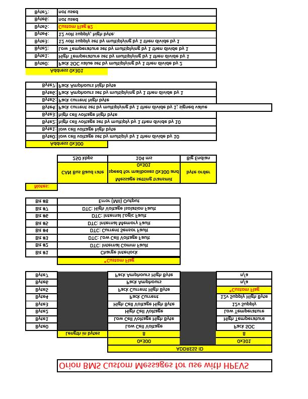
76 76 P age
Standard Operating Procedures
 1790-105 La Costa Meadows San Marcos, CA 92078 (888) 591-5830 Standard Operating Procedures Instructions for Program and Diagnose Modes Primary and Secondary Controllers Generic Software Version 5.11 and
Product Overview... 3 Items Included... 3 Precautions... 4 Minimum System Requirements... 4 Software Installation... 5 Software Registration
 Version 1.2 8/23/2010 TABLE OF CONTENTS Product Overview... 3 Items Included... 3 Precautions... 4 Minimum System Requirements... 4 Software Installation... 5 Software Registration... 6 NovaLink Instructions...
FlexPak 3000 Drive Operator Interface Module (OIM) User s Guide
 User s Guide") FlexPak 3000 Drive Operator Interface Module (OIM) User s Guide Instruction Manual D2-3344 The information in this manual is subject to change without notice. Throughout this manual, the following notes
FlexPak 3000 Drive Operator Interface Module (OIM) User s Guide Instruction Manual D2-3344 The information in this manual is subject to change without notice. Throughout this manual, the following notes
EV Controls user Guide
 EV Controls user Guide Copyright EV Controls Table of Contents Introduction... EV Controls System Features... General guidelines for installation... Inverter Electrical Pinout Sheet... Drive Inverter Connections...
ORION BMS BYTE STRUCTURE. USE WITH HPEVS DRIVE SYSTEMS Generic 5.37 and Higher
 620 Magnolia Avenue Ontario, CA 91762 (909) 923-1973 ORION BMS BYTE STRUCTURE USE WITH HPEVS DRIVE SYSTEMS Generic 5.37 and Higher Date: 2-8-18 Scope: The following details the information and set-up of
Diesel Particulate Filter DPF Service Regeneration Table 1: Service Regeneration Successful Table 2: Service Regeneration Unsuccessful
 Service Information 2007 Chevrolet Silverado - 4WD [1GCHK23657F529413] Sierra, Silverado VIN C/K Service Manual Engine Engine Controls and Fuel - 6.6L LMM Diagnostic Information and Procedures Document
Controller Pro Instruction Manual
 Controller Pro Instruction Manual These instructions cover: Installing Controller Pro Programming Troubleshooting Doc# Doc120-017 Revision: B ECO: 010507 Note: Document revision history and EC information
PRO ESC - LCD PROGRAM CARD USER MANUAL. The Fantom FR-10 PRO LCD Program Card only applies to the FR-10 PRO 1:10 scale, 2S, 160A brushless ESC.
 PRO ESC - LCD PROGRAM CARD USER MANUAL The Fantom FR-10 PRO LCD Program Card only applies to the FR-10 PRO 1:10 scale, 2S, 160A brushless ESC. The LCD Program Card can be used in two ways as follows: 1.
Table of Contents. Part I USB Communication. Part II User Interface. Part III User Settings (Tab Control) DFS-1000 Dataview. 2 File Menu.
 DFS-1000 Dataview. 2 File Menu.") 2 Table of Contents Part I USB Communication 3 1 Important... Information 3 2 Connecting... Controller 3 Part II User Interface 4 1 Overview... 4 2 File Menu... 5 3 Options... Menu 6 4 Help Menu... 6 5
2 Table of Contents Part I USB Communication 3 1 Important... Information 3 2 Connecting... Controller 3 Part II User Interface 4 1 Overview... 4 2 File Menu... 5 3 Options... Menu 6 4 Help Menu... 6 5
Motor Controllers. On-Road AC Motor Controller. Model 1239E.
 Motor Controllers Model 29E www.curtisinstruments.com The E difference A significant enhancement to the Curtis AC family, The E models utilize a powerful dual-microprocessor logic architecture to provide
Integrated AC Traction & DC Pump System Controller Model 1298
 Motor Controllers Integrated AC Traction & DC Pump System Controller Model 298 www.curtisinstruments.com Model 298 The Curtis Model 298 combines advanced control of AC induction traction motors with solid
INSTRUCTIONS EV100 HANDSET
 GEH-5716 GENERAL The Handset is a multi-functional tool to be used with the EV100/200 LX and LXT SCR controls. The Handset consist of a Light Emitting Diode (LED) display and a keyboard for data entry.
Controller Pro Instruction Manual
 Controller Pro Instruction Manual These instructions cover: Installing Controller Pro Programming Troubleshooting Doc# Doc120-017 Revision: D ECO: 102208 Note: Document revision history and EC information
GV3000/SE Operator Interface Module (OIM) User Guide Version 2.0 M/N 2RK3000
 User Guide Version 2.0 M/N 2RK3000") GV3000/SE Operator Interface Module (OIM) User Guide Version 2.0 M/N 2RK3000 Instruction Manual D2-3342-2 The information in this manual is subject to change without notice. Throughout this manual, the
GV3000/SE Operator Interface Module (OIM) User Guide Version 2.0 M/N 2RK3000 Instruction Manual D2-3342-2 The information in this manual is subject to change without notice. Throughout this manual, the
DC M2 OLED Meter Instructions PN 1830 / PN 1832 / PN 1833 / PN 1834
 DC M2 OLED Meter Instructions PN 1830 / PN 1832 / PN 1833 / PN 1834 Installation Checklist Check for components included Read Warning and Cautions Read QuickStart Installation Guide for mounting instructions
3GV M Modbus RTU Register Map
 Application Note AN-ODP- 38 3GV M Modbus RTU Register Map Author: Ning Xu, Invertek Drives Ltd Revision: 2.21 15 June 2007 General This document details the Modbus RTU memory mapping implemented in Optidrive
GV3000/SE 230 VAC 1-20 HP General Purpose (Volts/Hertz) and Vector Duty Drive Software Start-Up and Reference Manual Version 6.04
 and Vector Duty Drive Software Start-Up and Reference Manual Version 6.04") GV3000/SE 230 VAC 1-20 HP General Purpose (Volts/Hertz) and Vector Duty Drive Software Start-Up and Reference Manual Version 6.04 Instruction Manual D2-3387-4 The information in this manual is subject
GV3000/SE 230 VAC 1-20 HP General Purpose (Volts/Hertz) and Vector Duty Drive Software Start-Up and Reference Manual Version 6.04 Instruction Manual D2-3387-4 The information in this manual is subject
3000 Series Instructions Read Instructions Carefully!
 Series Instructions Read Instructions Carefully! With buttons Without buttons CURTIS INSTRUMENTS, INC. Kisco Avenue, Mt. Kisco, NY 9 Tel. (9) 9 www.curtisinst.com. Technical Specifications. Electrical
Instruction and Operations Manual
 1 GARTECH Enterprises, Inc. Rev 2 01-23-09 Instruction and Operations Manual Portable Test Cell Overview The primary purpose of the Portable Test Cell is to allow the user the ability to control the engine
INSTRUCTION MANUAL IM253 R0. AquaStart COMBINATION SOFT STARTERS START-UP MANUAL
 INSTRUCTION MANUAL IM253 R0 AquaStart COMBINATION SOFT STARTERS START-UP MANUAL INDEX Power Connections...3 Basic Wiring...4 Start-Up By Voltage Ramp...5 Local / Remote Modes...6 Control and Signal Connections...6
TR-TEXT_EC. Display module for use with the EMUS BMS from Elektromotus and motor controllers from Curtis Instruments
 TR-TEXT_EC Display module for use with the EMUS BMS from Elektromotus and motor controllers from Curtis Instruments Special features showing data from battery management system and motor controller on
LiquiFlo AC General Purpose (Volts/Hertz) and Vector Duty Drive Software Start-Up and Reference Manual Version 6.4
 and Vector Duty Drive Software Start-Up and Reference Manual Version 6.4") LiquiFlo AC General Purpose (Volts/Hertz) and Vector Duty Drive Software Start-Up and Reference Manual Version 6.4 Instruction Manual D2-3410-7 The information in this manual is subject to change without
LiquiFlo AC General Purpose (Volts/Hertz) and Vector Duty Drive Software Start-Up and Reference Manual Version 6.4 Instruction Manual D2-3410-7 The information in this manual is subject to change without
Nanotec Electronic GmbH Gewerbestrasse Landsham near Munich Tel: 089/ Fax: 089/
 Manual SMCI-46 Positioning Control (Including Output Module) -1- Contents Page 1 General -3-2 Inputs/outputs and functions -4-2.1 Inputs -6-2.2 Outputs -7-2.3 Pushbuttons -7-2.4 Switches -8-2.5 Serial
EnCell Battery Cell Monitor
 EnCell Battery Cell Monitor Instruction Manual Model RCM15S12 NERC Compliant YO R U H T PA TO Z O R E W O D N M I T E enchargepowersystems.com sales@enchargepowersystems.com (888) 407.5040 Contents 1 Warnings,
Optidrive Applications Support Library
 Optidrive Applications Support Library Application Note Title AN-ODE-3-038 Related Products Optidrive E3 Overview Level 3 Modbus RTU Control and Register Mapping 1 Fundamental - No previous experience
M2 OLED Temperature Monitor Instructions PN 1841
 M2 OLED Temperature Monitor Instructions PN 1841 Installation Checklist Check for components included Read Warning and Cautions Read page 3 for mounting instructions Read System Overview, Mounting Considerations,
AC M2 OLED Meter Instructions PN 1836/ PN 1837 / PN 1838
 AC M2 OLED Meter Instructions PN 1836/ PN 1837 / PN 1838 Installation Checklist Check for components included Read Warning and Cautions Read QuickStart Installation Guide for mounting instructions Read
Component Tests User Manual
 Component Tests User Manual February 2009 EAZ0007E70C Rev. C Trademarks Acknowledgements Snap-on, Scanner, Fast-Track, and MODIS are trademarks of Snap-on Incorporated. All other marks are trademarks or
Torque Series LCD Remote Panel Installation/Operation Manual Model: TQ-DSP-12/24
 Torque Series LCD Remote Panel Installation/Operation Manual Model: TQ-DSP-12/24 Section Page Introduction 1 Materials Provided 1 I) Safety Instructions 1 A) Inverter Safety Instructions 1 B) Battery Safety
EMCP 4.4 Simulator Manual. Author: Lucas Tolbert CIC Engineering 345 Center Street East Peoria, IL
 EMCP 4.4 Simulator Manual Author: Lucas Tolbert CIC Engineering 345 Center Street East Peoria, IL Date of Origin: 11/23/2010 Overview This document will detail the features and operation of the EMCP 4.4
User Manual. HyPer 9 IS. HyPer 9 IS User Manual Version 05 NetGain Motors, Inc. Page 1 of 27
 User Manual HyPer 9 IS HyPer 9 IS User Manual Version 05 NetGain Motors, Inc. Page 1 of 27 Table of Contents Warning and Caution... 4 Safety Information... 4 DISCLAIMER:... 5 Main Wiring Diagram... 6 Wire
AC Variable Speed Drive 0.75kW 250kW / 1HP 350HP Volt 1 & 3 Phase. Advanced User Guide Revision 1.10
 AC Variable Speed Drive 0.75kW 250kW / 1HP 350HP 200 480 Volt 1 & 3 Phase Advanced User Guide Revision 1.10 Optidrive P2 Parameter Set Overview 1 This Document is for use with version 1.20 Firmware. Advanced
Optidrive VTC Modbus RTU Register Map
 Application Note AN-VTC- 39 Optidrive VTC Modbus RTU Register Map Author: Ning Xu, Invertek Drives Ltd Revision: 2.21 6 September 2006 General This document details the Modbus RTU memory mapping implemented
Torque Control Verifier
 Torque Control Verifier Instruction Manual Revision 1.2 September 2002 Please Read and Understand Instructions Before Attempting Installation Torque Control Verifier Contents: Quick Start Introduction
用户手册. KT-LCD6 ebike Special Meter
 用户手册 User Manual KT-LCD6 ebike Special Meter WWW.SZKTDZ.COM Contents Preface... 4 Outlook and Size... 4 Meter Dimension 4 Button Box Dimension.. 4 Main Material and Color.... 5 Wiring Schematic.. 5 Installation
SECTION 5 HSLRT6 WINDOWS BASED SETUP PROGRAM REFERENCE
 The Windows based set-up program is menu driven, allowing the user to easily view data, alter setup variables or set machine timing (machine offset, timing signal locations, etc.), using a PC running the
INTERFACE & SOFTWARE GUIDE
 TM INTERFACE & SOFTWARE GUIDE Wireless Remote Display USB Converter Battery Sensor Setup DataLogger Software r e m o t e i n t e r f a c e escape enter status w w w. s k y s t r e a m e n e r g y. c o
ADR. - Configuration and Functionality USER MANUAL
 ADR - Configuration and Functionality USER MANUAL Installation Contents Installation... 3 Dimensions... 3 Configuration... 4 Connection to the ADR... 4 Password Support... 5 Device Configuration... 5 Device
Quickie HHP Programming Tree
 Program Operate Monitor Motor Controller General Creep DP Drive profiles System Actuators* Veer Comp Fwd Veer Comp Rev Latch speed step Soft stop Brake Parameters Enable encoders Dir Act SW1 Dir Act SW2
SERIES CMT CARBON MONOXIDE GAS TRANSMITTER
 SERIES CMT CARBON MONOXIDE GAS TRANSMITTER INSTALLATION OPERATION AND MAINTENANCE MANUAL DWYER INTRUMENTS, INC. PO BOX 373, MICHIGAN CITY, IN. 46360 USA PHONE: 800-872-9141 FAX: 219-872-9057 Web: www.dwyer-inst.com
IS35 Color Display. User Manual ENGLISH. simrad-yachting.com
 IS35 Color Display User Manual ENGLISH simrad-yachting.com Preface Navico is continuously improving this product, therefore we retain the right to make changes to the product at any time which may not
Safety Instructions 1-1 Avoid unintended Start General Description 2-2
 Contents Contents 1 Safety and precautions 1-1 Safety Instructions 1-1 Avoid unintended Start. 1-1 2 Introduction 2-1 General Description 2-2 3 Supported Configuration 3-1 Introduction 3-1 Fixed-speed
QUICK REFERENCE GUIDE
 acknowledges changed values, fault history, and is pressed to enter program resets starts the motor when the panel is the stops the motor when the panel is the - and I/O CONNECTIONS SCREEN DISPLAYS QUICK
18805 Adams Ct., #110 ~ Morgan Hill, CA 95037, USA ~ ~ ~
 1 of 8 WASHLINK SYSTEMS Yaskawa V1000 Basic User Guide This document provides basic information for navigating and adjusting your Washlink Systems supplied Yaskawa V1000 Variable Frequency Drive. When
Advanced Features. High Performance Stepper Drive Description. Self Test and Auto Setup
 www.applied-motion.com STAC6 High Performance Stepper Drive Description The STAC6 represents the latest developments in stepper drive technology, incorporating features that will derive the highest performance
INSTALLATION INSTRUCTIONS 5" SINGLE CHANNEL ULTIMATE TACH
 Instr. No. 2650-887C INSTALLATION INSTRUCTIONS 5" SINGLE CHANNEL ULTIMATE TACH MODEL 6871, 6872, 6873, 6874, 6875, 6877 IMPORTANT WEAR SAFETY GLASSES 5 4 6 COPYRIGHT PATENT PENDING 3 7 8 PLAYBACK 9 2 0
BOWMONK 2000 OPERATING MANUAL
 BOWMONK 2000 OPERATING MANUAL BOWMONK 2000 Components Pedal Force Transducer: The Pedal Force Transducer (PFT) is a strain gauge sensor that shows the forces necessary to stop the vehicle in Newton. Connect
Figure 18: Basic input port drawing.
 Appendix A Hardware Inputs The mx_ctlr.0 board has several different types of inputs and outputs allowing for a wide range of functions and actions. The inputs for the board can be broken into three basic
Installation, Operation and Maintenance Manual
 Document 481200 VGD-100 Vari-Green Drive Installation, Operation and Maintenance Manual Please read and save these instructions for future reference. Read carefully before attempting to assemble, install,
Abstract. GLV User Manual 1
 GLV User Manual 1 Abstract This user manual is a high level document that explains all operational procedures and techniques needed to operate the GLV system in a safe and effective manner. Anyone operating
Unidrive M200, M201 (Frame 1 to 4) Quick Start Guide
 Quick Start Guide") This guide is intended to provide basic information required in order to set-up a drive to run a motor. Please refer to the Unidrive M200 / M20 User Guide which is available to download from www.controltechniques.com/user
This guide is intended to provide basic information required in order to set-up a drive to run a motor. Please refer to the Unidrive M200 / M20 User Guide which is available to download from www.controltechniques.com/user
Wagner Smart Screen Service/Troubleshooting Screens
 Section 7-2 Wagner Smart Screen Service/Troubleshooting Screens Menu Button PIN code login When you fi rst click on the Menu button, you will be prompted for a PIN code. Enter 0070 and click the check
INSTALLATION DKM-409 NETWORK ANALYSER WITH HARMONIC MEASUREMENT AND SCOPEMETER. Before installation:
 DKM-409 NETWORK ANALYSER WITH HARMONIC MEASUREMENT AND SCOPEMETER The DKM-409 is a precision instrument designed for displaying various AC parameters in 3-phase distribution panels. Thanks to its isolated
FIRING SYSTEMS 270 Old Dublin Rd PETERBOROUGH N.H PHONE FAX
 FIRING SYSTEMS 270 Old Dublin Rd PETERBOROUGH N.H. 03458 PHONE 603-924-4251 FAX 603-924-6748 www.pyromate.com pyromate@monad.net Firmware Version 2.02 Page 1 of 19 Table of Contents Features of the Night
The uscope Getting started
 Introduction (fw 5.11) AES uscope Manual The uscope Getting started The uscope! A single channel, pocket-sized, digital storage oscilloscope that s small, quick, and powerful. Automotive presets get you
Energy Management System. Operation and Installation Manual
 Energy Management System Operation and Installation Manual AA Portable Power Corp 825 S 19 TH Street, Richmond, CA 94804 www.batteryspace.com Table of Contents 1 Introduction 3 2. Packing List 5 3. Specifications
Optidrive Applications Support Library
 Optidrive Applications Support Library Application Note Title AN-ODV-3-038 Related Products Optidrive Eco Overview Level 3 Modbus RTU Control and Register Mapping 1 Fundamental - No previous experience
Operation Manual CX20 1/8 DIN Microcomputer Based Conductivity/Resistivity Controller
 Operation Manual CX20 1/8 DIN Microcomputer Based Conductivity/Resistivity Controller 11751 Markon Drive Garden Grove, CA. 92841 U.S.A. pg. 1 CONTENTS GENERAL INTRODUCTION.....3 INITIAL INSPECTION......3
DV-300 DC DRIVE. DV-300 DC Drive
 DV-300 DC Drive The DV-300 is a three phase, six-pulse converter which is available in either non-regenerative or fully regenerative design. The DV-300 Drive Controller allows for precise regulation of
Trouble Shooting Leveling Control Box Electric Jacks. Touch Pad LED Probable Cause Solution
 Trouble Shooting Leveling Control Box 140-1224 Electric Jacks Copyright Power Gear Issued: January 2013 #82-L0524, Rev. OA Touch Pad LED Probable Cause Solution 1. On/Off LED will not light 2. Wait LED
用户手册. User Manual. S-LCD8 ebike Special Meter
 用户手册 User Manual S-LCD8 ebike Special Meter WWW.BMSBATTERY.COM Contents Preface... 4 Outlook and Size... 4 Meter Dimension 4 Button Box Dimension..5 Main Material and Color.... 5 Wiring Schematic.. 5 Installation
DTC P0AA6 - High Voltage Isolation Fault
 DTC P0AA6 - High Voltage Isolation Fault Product Family Orion BMS [Original] (24-180 Cell) Orion BMS 2 (24-180 Cell) Orion JR (16 Cell) Fault Supported YES YES NO FAULT DESCRIPTION This code is set when
WHIPPLE FLARE FLASH Instruction Manual
 WHIPPLE FLARE FLASH Instruction Manual 2015 AND UP Ford MUSTANG/F150 WHIPPLE SUPERCHARGERS 3292 NORTH WEBER AVE FRESNO, CA 93722 TEL 559.442.1261 FAX 559.442.4153 A color PDF of this manual is available,
SIMOREG 6RA70 DC MASTER Electronics
 SIMOREG 6RA70 DC MASTER Electronics Up to this point we have looked at the power components of a DC Drive necessary to control the speed of a DC motor. The actual control of these components is accomplished
Truckweigh. operators sheet STGGLOBAL.NET
 Truckweigh operators sheet 1300 998 784 STGGLOBAL.NET FRONT PANEL FUNCTIONALITY The various screens and menus are accessed using the four buttons located around the LCD display, described briefly below.
BMS: Installation Manual v2.x - Documentation
 Page 1 of 7 BMS: Installation Manual v2.x From Documentation This section describes how external peripheral devices are connected and additional functions of the BMS are used. I you have not done so already,
Dryer. M720 Programming and Operation Manual. July 15, 2015 Revision 1.51
 Dryer M720 Programming and Operation Manual July 15, 2015 Revision 1.51 Contents 1 Important Safety Information 1 1.1 FOR YOUR SAFETY - CAUTION!............................. 1 2 Control Overview 2 2.1
Index. What is FIRESTORM? Find out on the next page. What is Mallory FIRESTORM...3. Features & Benefits...4. Dare to Compare Charts...
 BUYERS GUIDE Index What is Mallory FIRESTORM...3 Features & Benefits...4 What is FIRESTORM? Find out on the next page. Dare to Compare Charts... 5-11 How to Buy... 12-14 New Product Data Sheets...Appendix
Innovative Electronics for a Changing World. NPM-R10 Remote Network Power Monitor. With optional relay board and GSM module INDEX
 Innovative Electronics for a Changing World NPM-R10 Remote Network Power Monitor With optional relay board and GSM module INDEX 1. SYSTEM DESCRIPTION 2. BOARD CONNECTIONS terminals and indicators 3. CONNECTION
Series IZH10. Handheld Electrostatic Meter. How to Order. Accessories and Option / Part Number for Individual Parts.
 Peak G 15min Handheld Electrostatic Meter Series IZH10 How to Order IZH10 Option Nil H None High-voltage measuring handle Accessories and Option / Part Number for Individual Parts The ground wire and soft
MT-150. RENOGY 150A Peak High Precision Watt Meter and Power Analyzer E. Philadelphia St., Ontario CA Version: 1.
 MT-150 RENOGY 150A Peak High Precision Watt Meter and Power Analyzer 0 2775 E. Philadelphia St., Ontario CA 91761 1-800-330-8678 Version: 1.1 Important Safety Instructions Please save these instructions.
Monitored Power Supply INSTRUCTION MANUAL
 Monitored Power Supply INSTRUCTION MANUAL C.E. Electronics Inc. 2107 Industrial Drive Bryan, OH 43506 (419) 636-6705 E-mail: sales@ceelectronics.com www.ceelectronics.com 2 i TABLE OF CONTENTS Quick Start
用户手册. User Manual. KT-LCD5 ebike Special Meter
 用户手册 User Manual KT-LCD5 ebike Special Meter WWW.SZKTDZ.COM Contents Preface... 3 Outlook and Size.. 3 Meter Dimension 3 Main Material and Color....... 3 Wiring Schematic. 3 Installation Instruction..
CENTURION Pro Diagnostic Motorcycle Scan Tool USER S GUIDE. Version 1.0
 CENTURION Pro Diagnostic Motorcycle Scan Tool USER S GUIDE Version 1.0 CHAPTER 1: Preliminaries Introduction Centurion is a user-friendly tool that can diagnose engine and system problems and perform many
MRZJW3- SETUP154E. General-Purpose AC Servo Servo Configuration Software MODEL INSTALLATION GUIDE
 General-Purpose AC Servo Servo Configuration Software MODEL MRZJW3- SETUP154E INSTALLATION GUIDE Thank you for choosing the Mitsubishi general-purpose AC servo Servo Configuration Software. To optimize
SilverLeaf RV-C Control System Training Manual
 2013 SilverLeaf RV-C Control System Training Manual Newmar Corporation Revised Jan. 2013 Newmar SilverLeaf RV-C Control System Operation/Set-UP Manual SCREEN ACCESS Please be aware that not all of the
WHIPPLE FLARE FLASH Instruction Manual
 WHIPPLE FLARE FLASH Instruction Manual 2015 AND UP Ford MUSTANG/F150 WHIPPLE SUPERCHARGERS 3292 NORTH WEBER AVE FRESNO, CA 93722 TEL 559.442.1261 FAX 559.442.4153 A color PDF of this manual is available,
LDC x120A Single Channel Forward/Reverse Brushed DC Motor Controller
 LDC1450 1x120A Single Channel Forward/Reverse Brushed DC Motor Controller Roboteq s LDC1450 controller is designed to convert commands received from an RC radio, Analog Joystick, wireless modem, PC (via
Control system MultiDrive 2 with D3 joysticks
 means total control Control system MultiDrive 2 with D3 joysticks Technical description Control system MultiDrive 2 with D3 joysticks D3 joysticks and Display... Driver display With their comfortable pistol
Family Software 3164 Surrey Lane Aston, PA (610)
") Family Software 3164 Surrey Lane Aston, PA 19014 (610) 497-5561 'Drag Racing Computers and Software' - www.ifamilysoftware.com DataMaster Sportsman Computer- Instructions Introduction Congratulations on
Family Software 3164 Surrey Lane Aston, PA 19014 (610) 497-5561 'Drag Racing Computers and Software' - www.ifamilysoftware.com DataMaster Sportsman Computer- Instructions Introduction Congratulations on
ARROW 3. TRACK A. 4. DISPLAY
 ELIMINATOR 2000 INSTRUCTIONS Table of Contents 1. PRACTICE A. TREE Key 1. Change Full to Pro Tree 2. Change Tree Speed (4 tenths or 5 tenths) 3. Change Top Bulb Lock (Cross Talk) On / Off 4. Change Rollout
Manual. C500B LCD Instructions
 Manual C500B LCD Instructions CONTENT ABOUT THE USER MANUAL 3 OUTLOOK AND SIZE 3 MATERIAL AND COLOR 3 BUTTON DEFINITION 4 FUNCTION SUMMARY 5 FULL VIEW AREA 7 NORMAL VIEW AREA 7 NORMAL OPERATION 8 1.ON/OFF
DATE ( / 7. / 1. / / 3. / / 5. / 6. / TIME
 ELIMINATOR 2000 INSTRUCTIONS Table of Contents 1. PRACTICE A. TREE Key 1. Change Full to Pro Tree 2. Change Tree Speed ( 4 tenths or 5 tenths) 3. Change Rollout Out Separate Full and Pro Tree 4. Change
CurveMaker HD v1.0 Dyna 2000 Programmable Ignition programming software
 Contents CurveMaker HD v1.0 Dyna 2000 Programmable Ignition programming software Dynatek 164 S. Valencia St. Glendora, CA 91741 phone (626)963-1669 fax (626)963-7399 page 1) Installation 1 2) Overview
INSTRUCTION MANUAL STATION CONTROLLER SC1000 MOTOR PROTECTION ELECTRONICS, INC.
 INSTRUCTION MANUAL STATION CONTROLLER SC1000 MOTOR PROTECTION ELECTRONICS, INC. 2464 Vulcan Road, Apopka, Florida 32703 Phone: (407) 299-3825 Fax: (407) 294-9435 Revision Date: 9-11-08 Applications: Simplex,
Manual. CAN Color Instrument. Curtis Instruments, Inc. 200 Kisco Avenue Mt. Kisco, NY Read Instructions Carefully!
 Manual CAN Color Instrument Curtis Instruments, Inc. 200 Kisco Avenue Mt. Kisco, NY 10549 www.curtisinstruments.com Read Instructions Carefully! Specifications are subject to change without notice. 2012
User Manual. HyPer 9 IS. HyPer 9 IS User Manual Version 04 NetGain Motors, Inc. Page 1 of 23
 User Manual HyPer 9 IS HyPer 9 IS User Manual Version 04 NetGain Motors, Inc. Page 1 of 23 Table of Contents Warning and Caution... 4 Safety Information... 4 DISCLAIMER:... 5 Main Wiring Diagram... 6 Wire
CDR File Information. Comments Toyota 86 Registration 1ETM870 Speedometer Reading Kms. Data Limitations CDR Record Information:
 IMPORTANT NOTICE: Robert Bosch LLC and the manufacturers whose vehicles are accessible using the CDR System urge end users to use the latest production release of the Crash Data Retrieval system software
D115 The Fast Optimal Servo Amplifier For Brush, Brushless, Voice Coil Servo Motors
 D115 The Fast Optimal Servo Amplifier For Brush, Brushless, Voice Coil Servo Motors Ron Boe 5/15/2014 This user guide details the servo drives capabilities and physical interfaces. Users will be able to
FOR SERVICE TECHNICIAN S USE ONLY
 Tech Sheet Do not discard DANGER WARNING Electrical Shock Hazard Only authorized technicians should perform diagnostic voltage measurements. After performing voltage measurements, disconnect power before
32MP Gateway. Overview and Configuration Manual
 32MP Gateway Overview and Configuration Manual 32MP Gateway Overview and Configuration Manual This document is the property of Carrier Corporation and is delivered on the express condition that it is not
Easy Start Guide. Parker SSD Drives 650 Series Frequency Inverter available from Parker.InverterDrive.com
 Parker SSD Drives 650 Series Frequency Inverter available from Parker.InverterDrive.com This guide is intended to compliment the user manual provided by the manufacturer. It is provided as a basic introduction
Sierra Dual 24 Volt Brushless DC Motor Controller Product Specification. Assembly 025F0348
 Sierra Dual 24 Volt Brushless DC Motor Controller Product Specification Assembly Revision History ECN # Date Rev Description By EC77363 03/15/17 A Initial Release K. Jones EC81620 11/15/17 B Added Agency
AC INDUCTION MOTOR CONTROLLER MODELS 1236E / 1238E
 AC INDCTION MOTOR CONTROLLER MODELS 6E / 8E The E difference A significant enhancement to the Curtis AC family, The E models utilize a powerful dual-microprocessor logic architecture to provide improved
MotionView Configuration and Programming Software USER S MANUAL
 MotionView Configuration and Programming Software USER S MANUAL IM94MV01C Table of Contents 1 MotionView Software Overview......................................... 3 1.1 Installation and Package Revision.................................................
4. Setting parameters
 . Setting parameters.1 Setting and Display Modes The VF-nC3 has the following three display modes. Standard monitor mode The standard inverter mode. This mode is enabled when inverter power goes on. This
SYSTEMAX 2014 MULTIVALVE ELECTRONIC CONTROLLER WITH DEMAND RECALL
 MULTIVALVE ELECTRONIC CONTROLLER WITH DEMAND RECALL Service Manual Table of Contents Item Page Introduction and General Description...3 Front Panel View and Description...3 Modes of Operation...4 Front
INTRODUCTION. FX-1 Operations Manual. Standard Features. Optional Features. Read This Manual Completely Before Proceeding!
 INTRODUCTION The FX-1 Control is designed for use with all direct expansion, reverse cycle air conditioning systems. FX-1 has a universal power supply that operates on 115, 230, 50 or 60 Hz AC power. FX-
INSTALLATION AND OPERATING INSTRUCTIONS DSST SYSTEM
 INSTALLATION AND OPERATING INSTRUCTIONS DSST SYSTEM PROPORTIONAL and NON-PROPORTIONAL TOGGLE SWITCH RADIO REMOTE CONTROL SYSTEM MODEL FHSTP/DSSTP SERIES FHST/DSST SYSTEM DESCRIPTION The DSST Wireless Control
User's Guide. For CarChip and CarChip E/X 8210 & 8220
 User's Guide TM For CarChip and CarChip E/X 8210 & 8220 Product Number: 8210, 8220 Davis Instruments Part Number: 7395.064 DriveRight CarChip User s Manual Rev A (January 2, 2003) Davis Instruments Corp.,