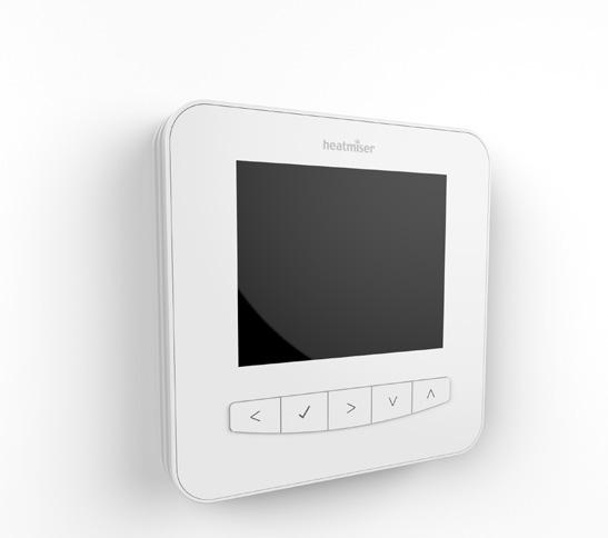
Model: Available in : Sapphire Black and Glacier White
|
|
|
- Thomasina Gwendoline Malone
- 5 years ago
- Views:
Transcription

1 1
2 Model: Available in : Sapphire Black and Glacier White 1
3 Table of Contents Product Image 1 Locking/Unlocking the SmartStat Table of Contents 2 Standby/Away Mode Mode What is a Programmable Room Thermostat? Installation Procedure Mode Select / Factory Reset WiFi Setup - Automatic WiFi Pairing Setup with - Manual SmartStat App Pairing with the SmartApp Power ON/OFF Holiday Programming Optional Features Re-calibrating the Thermostat Error Codes Thermostat Profiles Mode Wiring Diagram Thermostat Mode Wiring Diagram Mode 1 - Thermostat LCD Display Temperature Display Setting the Time & Date Setting the Comfort Levels Setting the Temperature Temperature Hold Mode 2 - Time Clock LCD Display Setting the Switching Times Timer Boost Optional Features Optional Features Table Time Clock Mode Wiring Diagrams
4 What is a Programmable Room Thermostat? A programmable room thermostat is both a programmer and a room thermostat. A programmer allows you to set On and Off periods to suit your own lifestyle. A room thermostat works by sensing the air temperature, switching on the heating when the air temperature falls below the thermostat setting, and switching it off once this set temperature has been reached. So a programmable room thermostat lets you choose what times you want the heating to be on, and what temperature it should reach while it is on. It will allow you to select different temperatures in your home at different times of the day (and days of the week) to meet your particular needs and preferences. Setting a programmable room thermostat to a higher temperature will not make the room heat up any faster. How quickly the room heats up depends on the design and size of the heating system. Similarly reducing the temperature setting does not affect how quickly the room cools down. Setting a programmable room thermostat to a lower temperature will result in the room being controlled at a lower temperature, and saves energy. 3
5 The way to set and use your programmable room thermostat is to find the lowest temperature settings that you are comfortable with at the different times you have chosen, and then leave it alone to do its job. The best way to do this is to set the room thermostat to to a a low temperature say say 18 C and then turn it up by 1 C each day until you you are are comfortable with with the the temperature. You won t have to adjust the thermostat further. Any adjustment above this setting will waste energy and cost you more money. You are able to temporarily adjust the heating program by overriding or using the temperature hold feature. These features are explained further on pages and of this manual. Programmable room thermostats need a free flow of air to sense the temperature, so they must not be covered by curtains or blocked by furniture. Nearby electric fires, televisions, wall or table lamps may also prevent the thermostat from working properly. 4
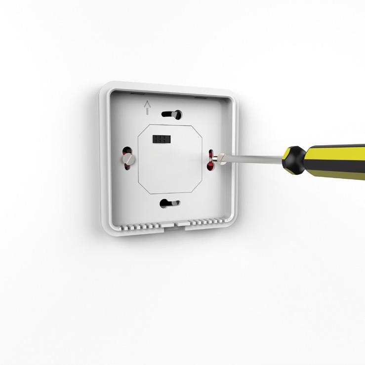
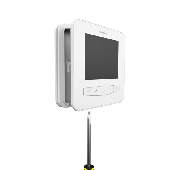
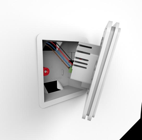
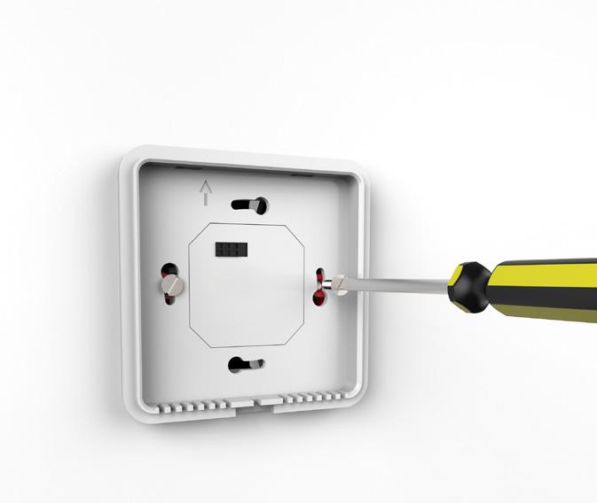
6 Installation Procedure Do Mount the SmartStat at eye level. Read the instructions fully so you get the best from our product. Don t Do not install near to a direct heat source as this will affect functionality. Do not push hard on the LCD screen as this may cause irreparable damage. This SmartStat is designed to be flush mounted and requires a back box of 35mm (minimum depth) to be sunk into the wall prior to installation. Step 1 Using a small screwdriver, slightly loosen the screw from the bottom face of the SmartStat. You can then carefully separate the front half from the back plate. Step 2 Place the SmartStat front somewhere safe. Terminate the SmartStat as shown in in the diagrams on on pages of of this this booklet. Note: For time clock wiring connections, terminate as shown on pages Step 3 Screw the SmartStat back plate securely into the back box. Step 4 Clip the front of the SmartStat onto the back plate, securing it in place with the retaining screw. 5
7
8 Mode Select / Factory Reset This SmartStat can either be used as a thermostat or a time clock. Thermostat This SmartStat mode can is the either default be used setting. as a thermostat or a time clock. Thermostat mode is the default setting. To reset the device to factory default settings or change between thermostat / time To clock change modes, between follow thermostat these steps. & time clock modes, follow these steps. Use the Left / Right keys to scroll to Setup... Press and hold the Tick key for 5 seconds... Use the Up / Down keys to scroll between modes... Press the Tick key to confirm selection... The SmartStat will reset all parameters and restart in the selected mode. Note: The Factory SmartStat reset will reset cancel all all parameters and that restart were entered in the selected during the mode. set-up and pairing operations. These processes must be repeated after factory reset is completed. Note: The Mode Select function will reset all parameters that were entered during the set-up and pairing operations. These processes must be repeated after the restart has completed. 7
9 Thermostat Mode Select mode Time Restart Clock Screen Mode Thermostat Mode Select mode Time Restart Clock Screen Mode 8
10 WiFi Setup - Automatic To connect To connect the the SmartStat with with the the WiFi WiFi network follow follow these these steps. steps. Use Use the the Left // Right keys to scroll to Setup and press Tick Tick... Use Use the the Up/Down arrow keys key to to scroll to to WiFi Setup and press Tick... Use the Up / Down keys to scroll to Scan Available Networks... Automatic Setup (if the SSID is visible): Press the Tick key... Use the Up / Down keys to scroll to Scan Available Networks... The SmartStat will scan and list all available WiFi networks. Press the Tick key... Use the Up / Down keys to select a network... The SmartStat will scan and list all available networks. Press the Tick key... Use the Up / Down keys to select a network... Using the Arrow keys to navigate and the Tick key to select, Press the Tick key... enter the network key using the keypad... Using the Arrow keys to navigate and the Tick key to Once the network key has been entered, use the arrow keys select, enter the network key using the keypad... and navigate to Join'... Using the Down key, navigate to Join... Press the Tick key to confirm... Press the Tick key to confirm... The SmartStat will then connect to the chosen WiFi network. During this process the WiFi The icon and SmartStat Connecting will attempt will be displayed. to connect If successful to the network. a Tick symbol will be displayed During next to the this network process name, the the WiFi SmartStat icon and will Attempting then return to the Connect main display. will be displayed. * Note: To join a closed/hidden WiFi network, within WiFi Setup, use the up/down keys to scroll to If successful Tick will be displayed next to the network name. Other. Here you can manually enter the SSID, security type and security key then select Join. 9
11 Pairing with SmartStat App Download the FREE Heatmiser SmartStat App from the Apple App Store, Google Play Store or Amazon App Store. Open the SmartStat App, create your account & login Press Add Location Enter a name for your location, for example Home Select the correct time zone for your location, for example GMT then press Submit Once the location has been created, now add your SmartStats to the location. Select 1. WiFi Add Setup Zone and Menu enter the first zone title, for 2. List example of Networks Living Room, press Add Zone' On the SmartStat, use the Left / Right keys to scroll to setup and press Tick... Pairing with App will be highlighted in the menu, press the Tick key to start pairing... Both the App & the SmartStat will display a green tick symbol once pairing is successful Note: To pair more SmartStats to the location, select Add Zone within the Manage Zones section and repeat the steps above. 3. Network Key Entry 4. Connecting 10
: Use the Up / Down keys to scroll to Other... Press the Tick Key.")
12 Mode WiFi Setup 1 - Thermostat - Manual To connect the SmartStat with the WiFi network follow these steps. Use the Left / Right keys to scroll to Setup and press Tick... Use the Up/Down keys to scroll to WiFi Setup and press Tick... Manual Setup (if the SSID is not visible): Use the Up / Down keys to scroll to Other... Press the Tick Key... Using the Up / Down keys scroll to SSID and press Tick... Using the Arrow keys to navigate and the Tick key to select, enter the SSID name using the keypad... To confirm, scroll down to the return icon and press Tick... Using the Up / Down keys scroll to Key Type and press Tick... Using the Up / Down keys select the Key Type and Press Tick... Using the Up / Down keys scroll to Key and press Tick... Using the Arrow keys to navigate and the Tick key to select, enter the security key using the keypad... To confirm, scroll down to the return icon and press Tick... Use the Down/Left/Right keys to scroll to Join... Press the Tick key to confirm... 11

13 1 2 The SmartStat will attempt to connect to the network. During this process the WiFi icon and Attempting to Connect will be displayed. If successful a Tick will be displayed next to the network name WiFi Manual Setup Menu 2. SSID Name Entry Key Type Selection 4. Network Key Entry 9 12
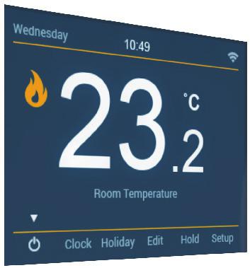
14 Pairing Main Display with SmartStat App To pair the SmartStat with the App, follow these steps. 1. Day Indicator - Displays the day of the week. Download the FREE Heatmiser SmartStat App from the Apple App Store, 2. Google Clock - Time Play Store, displayed Amazon in 24 hour App format. Store or Windows Phone App Store and 3. register Temperature an account. Format Degrees Celsius or Fahrenheit. 4. Open WiFi Indicator the SmartStat - Displayed App when and create connected your to account. a WiFi network. 5. Press Flame Add Symbol Location. Displayed when the thermostat is calling for heat and Enter flashes a name when optimum for your location start is active. and press Add location 6. You Frost now Protection have two Displayed minutes when to pair Away/Standby the SmartStat. modes are active. 7. On Holiday the SmartStat, Displayed use when the the Left thermostat / Right keys is in to holiday scroll to mode. setup 8. and Floor press Limit Tick Symbol... Displayed when the floor probe has reached the floor Pairing temperature with limit App configured will be highlighted in the setup in the menu. menu, press the Tick 9. key Main to Menu start pairing... Highlighted display indicates selected option. 10. Once Floor/Room the SmartStat Temp Indicates successfully the current pairs; press sensor finish mode. on the SmartStat App. Press the Tick key on the SmartStat to complete pairing Temperature Displays the current sensor temperature. 12. Keypad Lock Indicator Displayed when the keypad is locked. 13
15 Mode Temperature 1 - Thermostat Display This SmartStat can be configured for different sensor options such as built in air sensor, floor sensor or both. The display will clearly indicate which sensor is being used by showing either Room Temperature or Floor Temperature under the actual value. Room Temperature Floor Temperature When the SmartStat is set to use both the air & the floor sensor, the room temperature will be displayed by default. To view the current floor temperature, press and hold the Left and Right arrow keys for 5 seconds, the floor temperature will then be displayed
16 Setting the Time and Date Note: When the SmartStat is paired with the app, the time & date settings are automatically synchronised according to the location s time zone setting. To set the clock, follow these steps. Use the Left / Right keys to scroll to Clock... Press Tick to confirm selection... Use the Left / Right keys to scroll between Day/Month/Year values... Use the Up / Down keys to set the Day/Month/Year values... Press Tick to confirm selections and progress to Time... Use the Left / Right keys to scroll between hours and minutes... Use the Up / Down keys to set the hours/minutes values... Press Tick to confirm selection and return to the main display Setting the date 9 Setting the time 15
17 Comfort Main Display Levels Explained The SmartStat offers three program mode options; Weekday/Weekend programming, 7 1. Day programming Day Indicator and - Displays 24 Hour the programming. day of the week. You 2. also Clock have - the Time option displayed to use in the 24 SmartStat hour format. in Non-Programmable mode. The 3. SmartStat Temperature is supplied Format with Degrees comfort levels Celsius already or Fahrenheit. programmed, but these can be changed 4. WiFi easily. Indicator The default - Displayed times and when temperature connected settings to a WiFi are; network. 08: C Flame (Wake) Symbol 09:30 Displayed - 16 C (Leave) when the 16:30 thermostat - 22 C (Return) is calling for 23:00 heat - 17 C and (Sleep) flashes when optimum start is active. For 6. Weekday/Weekend Away Symbol programming, Displayed when the four Away comfort mode levels is active. are the same for Mon-Fri, but can be 7. different Holiday for Sat-Sun. Displayed For 7 Day when programming the thermostat each is day in holiday of the week mode. can have four different comfort 8. Floor levels. Limit In 24 Symbol Hour mode Displayed all days are when programmed the floor with probe the has same reached comfort the levels. floor To program temperature the comfort limit configured levels, use the in the Left setup / Right menu. keys to scroll to Edit Press Main Tick to Menu confirm Highlighted selection... display indicates selected option. 10. Floor/Room Temp Indicates the current sensor mode. Use the Up / Down keys to select day / period of week Temperature Displays the current sensor temperature. Press Tick to confirm selection Keypad Lock Indicator Displayed when the keypad is locked. Wake will now be highlighted and the current time and temperature settings shown. Press Tick to alter Wake settings... Use the Up / Down keys to set the time... 16
18 Use the Left / Right keys to scroll between hours and minutes... Temperature Display Press Tick to confirm... Use the Up / Down keys to set the temperature... This SmartStat can be configured for different sensor options such as built in air sensor, Press Tick to confirm the settings... floor sensor or both. The display will clearly indicate which sensor is being used by showing Press either Right Room arrow Temperature key... or Floor Temperature under the actual value. Leave will now be highlighted and the current settings will be displayed. Press Tick to alter the Leave settings... Repeat these steps to set all comfort levels. To blank or set a comfort level period to unused, first select the comfort level then press and hold the tick key for 5 seconds. 'Level unused' will appear in the corner of the display... When complete use the Right key to scroll to Done and press Tick... Program Mode Room Temperature Set Time Floor Temperature Set Temperature When the SmartStat is set to use both the air & the floor sensor, the room temperature will be displayed by default. To view the current floor temperature, press and hold the Left and Right arrow keys Comfort for 5 seconds, Level the floor temperature will then be displayed.... Done 17


19 Setting Temperature the Time Control and Date The Up / Down keys allow you to adjust the current set temperature... To set the clock, follow these steps. When Use you the press Left either / Right of keys these to keys, scroll you to Clock will see... the Set Temperature and the desired temperature value. Press Tick to confirm selection... Use the Up / Down keys to adjust the set value... Use the Left / Right keys to scroll between Day/Month/Year values... Press Tick to confirm settings... Use the Up / Down keys to set the Day/Month/Year values... Press Tick to confirm selections and progress to Time... Use the Left / Right keys to scroll between hours and minutes... Use the Up / Down keys to set the hours/minutes values... Press Tick to confirm selection and return to the main display... Set Temperature Note: This new temperature is maintained only until the next programmed comfort level. At this time, the thermostat will revert back to the programmed levels. Setting the date Setting the time 18

20 Temperature Comfort Levels Hold Explained The The temperature SmartStat offers hold three function program allows mode you to options; manually Weekday/Weekend override the current programming, operating program 7 Day programming and set a different and 24 temperature Hour programming. for a desired period. You also Use have the Left the / option Right keys to use to the scroll SmartStat to Hold in and Non-Programmable press Tick... mode. The SmartStat Use the Up is supplied / Down keys with to comfort set the levels desired already Hold time programmed,... but these can be changed easily. The default times and temperature settings are; Use the Left / Right keys to scroll between hours and minutes... 08:00 Press - 21 C Tick (Wake) to confirm 09:30 selection - 16 C (Leave)... 16:30-22 C (Return) 23:00-17 C (Sleep) For Weekday/Weekend Use the Up / Down programming, keys to set the desired four comfort Hold temperature levels are the same... for Mon-Fri, but can be different Press Tick for Sat-Sun. to confirm For selection 7 Day programming... each day of the week can have four different comfort levels. In 24 Hour mode all days are programmed with the same comfort levels. You will see the HOLD LEFT indication is displayed on screen. The time To program will countdown the comfort the set levels, duration use the and Left then / Right revert keys to the to scroll normal to program. Edit... Press Tick to confirm selection... Use the Up / Down keys to select day / period of week... Press Tick to confirm selection... HOLD LEFT Indicator and Wake will now be highlighted and the current hold time time and remaining temperature settings shown. Press Tick to alter Wake settings... Use the Up / Down keys to set the time... To cancel a temperature Hold, repeat these steps but reduce the Hold time to 00:00 hrs 19
21 Locking the SmartStat Use the Left / Right keys to scroll between hours and minutes... Press Tick to confirm... The SmartStat has a keypad lock facility. To activate the lock follow these steps. Use the Up / Down keys to set the temperature... Use the Left / Right keys to scroll to Hold & press Tick for 5 seconds... Press Tick to confirm the settings... The display will show 0000 and you will need to enter a four digit pin number. Press the Right arrow key... Use the Up / Down keys to enter values... Leave will now be highlighted and the current settings will be displayed. Use the Left / Right keys to move between digits... Press Tick to alter the Leave settings... Press Tick to confirm... Repeat these steps to set all comfort levels. The display will return to the main screen and display the keypad lock indicator... To deactivate a period hold Tick for 5 seconds... To enable keylock in time clock mode, select Boost, press & hold tick for 5 seconds. When complete use the Right key to scroll to Done and press Tick... Note: The keypad lock indicator is only displayed when the lock is active. Unlocking the SmartStat Program Mode Set Time To unlock the SmartStat press Tick once. The display will show **** and you will need to enter Set Temperature the four digit pin number you set previously. Use the Up / Down keys to enter values... Use the Left / Right keys to move between digits... Press Tick to confirm... The Comfort display will Level unlock and return to the main screen. Done 20
22 Standby/Away Temperature Control Mode The Up / Down keys allow you to adjust the current set temperature... Use the Left / Right keys to scroll to the Power Icon... When you press either of these keys, you will see the Set Temperature and The Frost Protection Symbol will toggle ON/OFF each time Tick is pressed... the desired temperature value. In Use this the mode, Up / the Down SmartStat keys to will adjust only the turn set the value heating... ON should the room temperature drop below the set Away Temperature. This is configured in the setup menu. Press Tick to confirm settings... If the heating is turned ON whilst in Standby/Away Mode, the Flame symbol will be displayed. To cancel the Standby/Away Mode, navigate to the Power button and press Tick... Set Temperature Note: Away & standby modes both mean the SmartStat is maintaining Frost a lower temperature to Protection give frost protection. Symbol Away is global meaning all zones on the system, Standby is used for individual zones. Note: This new temperature is maintained only until the next programmed comfort level. At this time, the thermostat will revert back to the programmed levels. 21


23 Temperature Power On/Off Hold The temperature heating is indicated hold function ON when allows the you Flame to manually Icon is displayed. override the current operating program and set a different temperature for a desired period. When the Flame Icon is absent, there is no requirement for heating to achieve the set temperature Use the but Left the / Right SmartStat keys to remains scroll to active. Hold and press Tick... To turn Use the the SmartStat Up / Down off keys completely, to set the scroll desired to the Hold Power time Icon... and hold the Tick Use key the for Left approximately / Right keys to 4 seconds scroll between until the hours display and goes minutes blank... The display Press Tick and to heating confirm output selection will... be turned OFF. To turn Use the the SmartStat Up / Down back keys ON, to press set the the desired Tick key Hold once temperature... Press Tick to confirm selection... SmartStat completely OFF SmartStat powered ON You will see the HOLD LEFT indication is displayed on screen. The time will countdown the set duration and then revert to the normal program. HOLD LEFT Indicator and hold time remaining To cancel a temperature Hold, repeat these steps but reduce the Hold time to 00:00 hrs 22
24 Locking Holidaythe SmartStat The In time SmartStat clock mode; has a keypad the timed lock output facility. will To be activate turned the off lock during follow the these holiday steps. period, then return Use the to Left the / programmed Right keys to settings scroll to once Hold the & press holiday Tick period for 5 seconds finishes.... In thermostat mode; the holiday function reduces the set temperature in your home The display will show 0000 and you will need to enter a four digit pin number. to the Away mode temperature setting that is configured in the setup menu. Use the Up / Down keys to enter values... The SmartStat will maintain this temperature for the duration of the holiday and will Use the Left / Right keys to move between digits... then automatically return to the program mode on your return. Press Tick to confirm... Use the Left / Right keys to scroll to Holiday and press Tick... The display will return to the main screen and display the keypad lock indicator... Using the Up / Down keys enter the number of days holiday... To enable keylock in time clock mode, select Boost, press & hold tick for 5 seconds. Press Tick to confirm settings... Note: The keypad lock indicator is only displayed when the lock is active. Unlocking the SmartStat To cancel the holiday, repeat these steps but reduce the Holiday duration to 00 days. To Note: unlock A holiday the SmartStat period does press not Tick start once. until The 00:00 display the next will day. show For **** example, and you if you will set need a to enter holiday the period four digit on Friday pin number for 2 days, you Saturday set previously. will be counted as the first day and the thermostat Use the will Up revert / Down back keys to the to programmed enter values... schedule at 00:00 on Monday. Use the Left / Right keys to move between digits... Press Tick to confirm... The display will unlock and return to the main screen. 23
25 Away Optional Mode Features Explained THE FOLLOWING SETTINGS ARE OPTIONAL AND IN MOST CASES Use the Left / Right keys to scroll to the Power Icon... NEED NOT BE ADJUSTED. The Away symbol will toggle ON/OFF each time Tick is pressed... Pairing With the App: This function is used to pair the SmartStat to the SmartStat App. In WiFi this Set-Up: mode, the This SmartStat function is will used only to connect turn the the heating SmartStat ON should with the the WiFi room network. temperature drop below the set Away Temperature. This is configured in the setup menu. If Switching the heating Differential: is turned ON This whilst function in Away allows Mode, you to the increase Flame the symbol switching will be differential displayed. of the thermostat. The default is 0.5 C which means that with a set temperature of 20 C, the To thermostat cancel the will Away switch Mode, the navigate heating on to at the 19.5 C Power and button off at and 20.0 C. press With Tick a 1 C... differential, the heating will switch on at 19.0 C and off at 20.0 C. Away Temperature: This is the temperature maintained when the thermostat is in Away Mode. The range is 7-17 C. The default is 12 C and is suitable for most applications. Output Delay: To prevent rapid switching, an output delay can be entered. This can be set from minutes. The default is 00 which means there is no delay. Temperature Away Symbol Up/Down Limit: This function allows you to limit the use of the up and down temperature arrow keys. This limit is also applicable when the thermostat is locked and so allows you to give others limited control over the heating system. Sensor Selection: On this SmartStat, you can select which sensor should be used. You can select between air temperature only, floor temperature, or both. When you enable both sensors, the floor sensor is used as a floor limiting sensor and is designed to prevent the floor from overheating. 24

26 Power On/Off Floor Temp Limit: This function is available when the floor sensor is enabled. You can set a floor limiting temperature between C (27 C is the default setting). The Note: heating Air Sensor is indicated only MUST ON NOT when be the used Flame to control Icon electric is displayed. underfloor heating. Floor Sensor or Both should be used. When the Flame Icon is absent, there is no requirement for heating to achieve the set temperature Optimum Start: but the Optimum SmartStat start remains will delay active. the start up of the heating system to the latest possible moment to avoid unnecessary heating and ensure the building is To turn the SmartStat off completely, scroll to the Power Icon and hold warm at the programmed time. The SmartStat uses the rate of change information the Tick key for approximately 4 seconds until the display goes blank... to calculate how long the heating needs to raise the building temperature 1 C (with The a rate display of change and heating of 20, the output SmartStat will be has turned calculated OFF. the heating needs 20 minutes to To raise turn the the building SmartStat temperature back ON, press 1 C) and the Tick starts key the once heating... accordingly. Rate of Change: Number of minutes for 1 C temperature rise. SmartStat completely OFF SmartStat powered ON Program Mode: The SmartStat offers three programming modes and the option of configuring it to work as a non-programmable thermostat. Weekday/ Weekend - allows you to program 4 comfort levels for the weekday and 4 different comfort levels for the weekend. 7 Day Program Mode - Each day has 4 comfort levels that can be programmed independently. 24 Hour Mode - All days are programmed the same and repeat continuously. Temperature Format: This function is used to select between C and F. Ambient Light Dimming: When this function is enabled, the light sensor will detect when to dim the backlight when the ambient light levels drop. If you turn the room lights off, the backlight will dim so the SmartStat does not light up the room. 25

27 Adjusting Holiday the Optional Settings In time Use clock the Left mode; / Right the timed keys to output select will Setup be... turned off during the holiday period, then return to the programmed settings once the holiday period finishes. In thermostat Press Tick mode; to confirm the holiday selection function... reduces the set temperature in your home to the Away mode temperature setting that is configured in the setup menu. The SmartStat will maintain this temperature for the duration of the holiday and will then automatically return to the program mode on your return. Use the Left / Right keys to scroll to Holiday and press Tick... Using the Up / Down keys enter the number of days holiday... Press Tick to confirm settings... To cancel the holiday, repeat these steps but reduce the Holiday duration to 00 days. Features Menu Feature Editing Note: A holiday period does not start until 00:00 the next day. For example, if you set a holiday Use period the Up on / Friday Down for keys 2 days, to scroll Saturday through will features be counted... as the first day and the thermostat Use the will Left revert / Right back keys to the to change programmed page schedule... at 00:00 on Monday. Press Tick to edit a feature... Use the Up / Down keys to adjust the feature setting... Press Tick to confirm settings and return to the feature menu... 26
28 Optional Features Settings Explained - Feature Table THE FEATURE FOLLOWING SETTINGS ARE OPTIONAL SETTING AND IN MOST CASES NEED NOT BE ADJUSTED. Pairing with App Used to add pair with the SmartStat App Pairing With the App: This function is used to pair the SmartStat to the SmartStat App. WiFi Setup Used to connect to the WiFi network WiFi Switching Set-Up: Differential This function is used 0.5 to connect C (0.5 C the = SmartStat Default) with the WiFi network. Switching Away Temperature Differential: This function 7-17 C allows (12 C you = Default) to increase the switching differential of the Output thermostat. Delay The default is 0.5 C 00 which - 15 Minutes means (00 that = Default) with a set temperature of 20 C, the thermostat Up/Down Temperature will switch Limit the heating 00 on - 10 C at 19.5 C (00 = Default) and off at 20.0 C. With a 1 C differential, the Sensor heating Selection will switch on at 19.0 C Built and in Sensor off at 20.0 C. (Default) Remote Air Sensor Away Temperature: This is the temperature maintained when the thermostat is in Away Floor Sensor Only Mode. The range is 7-17 C. The default Built in is & Floor 12 C Sensor and is suitable for most applications. Output Delay: To prevent rapid switching, Remote Air an & Floor output Sensor delay can be entered. This Floor can Temperature be set from Limit minutes. 20 C The - 45 C default (27 C = is Default) 00 which means there is no delay. Optimum Start hours (00 = Disabled as default) Temperature Up/Down Limit: This function allows you to limit the use of the up and Rate of Change Minutes to raise temperature by 1 C down temperature arrow keys. This limit is also applicable when the thermostat is locked Program Mode Weekday/Weekend (Default) and so allows you to give others limited control over the heating system. 7 Day Programming Sensor Selection: On this SmartStat, 24 Hour you Mode can select which sensor should be used. You can select between air temperature only, Non floor - Programmable temperature, or both. When you enable both sensors, Temperature the floor Format sensor is used as 00 a = floor C, 01 limiting = F (00 sensor = Default) and is designed to prevent the floor Ambient from Light overheating. Dimming On / Off 27
29 Re-calibrating the SmartStat Floor Temp Limit: This function is available when the floor sensor is enabled. You can set a floor limiting temperature between C (28 C is the default setting). If Note: you need Air Sensor to re-calibrate only MUST the NOT SmartStat, be used to follow control these electric steps. underfloor heating. Floor Sensor or Both should be used. Use the Left / Right keys to scroll to the Power Icon... Optimum Start: Optimum start will delay the start up of the heating system to the Press and hold Tick to turn the display OFF... latest possible moment to avoid unnecessary heating and ensure the building is warm Press at the and programmed hold the Tick time. and The Down SmartStat keys together uses the for rate 4 seconds of change... information to calculate The current how long temperature the heating will appear needs to on raise the the display. building temperature 1 C (with a rate Use of change the Up / of Down 20, the keys SmartStat to configure has calculated the new temperature the heating needs value minutes to raise the building temperature 1 C) and starts the heating accordingly. Press the Tick key to confirm the change and the display will go blank... Rate of Change: Number of minutes for 1 C temperature rise. Press the Tick key once to turn the thermostat ON... Program Mode: The SmartStat offers three programming modes and the option of configuring it to work as a non-programmable thermostat. Weekday/ Error Weekend Codes - allows you to program 4 comfort levels for the weekday The and SmartStat 4 different will display comfort an levels error for code the if weekend. there is a fault with the temperature sensor, these 7 Day error Program codes are Mode explained - Each below. day has 4 comfort levels that can be programmed independently. E0 = The internal sensor has developed a fault. 24 Hour Mode - All days are programmed the same and repeat continuously. E1 = The remote FLOOR probe has not been connected. Temperature The Format: remote This FLOOR function probe is used has not to select been between wired correctly. C and F. Ambient Light The Dimming: remote FLOOR When probe this function is faulty. is enabled, the light sensor will detect when to E2 dim = The the remote backlight AIR when probe the has ambient not been light connected. levels drop. If you turn the room lights off, the The backlight remote will AIR dim probe so the has SmartStat not been wired does not correctly. light up the room. The remote AIR probe is faulty. 28
30 Adjusting Wiring Diagram the Optional Volt Free Settings Output Use the Left / Right keys to select Setup... Press Tick to confirm selection... TIMER - RT2 RT1 N L NO NC COM Features Neutral Menu Feature Editing 230V Supply In Use the Up / Down Live keys to scroll through features... Use the Left / Right keys to change page... Volt Free Press Tick to Output edit a feature... Use the Up / Down keys to adjust the feature setting... Press Tick This to product confirm must settings only and be installed return to by the a qualified feature menu electrician... and comply with local installation regulations. 29
31 Optional Wiring Diagram Settings - Switch Feature Live Table Output FEATURE SETTING Pairing with App WiFi Setup Switching Differential Away Temperature Output Delay Up/Down Temperature Limit Sensor Selection - Used to add pair with the SmartStat App Used to connect to the WiFi network 0.5 o o C (0.5 o C = Default) 7 o - 17 o C (12 o C = Default) Minutes (00 = Default) TIMER 00 o - 10 o C (00 = Default) Built in Sensor (Default) Remote Air Sensor Floor RT2Sensor RT1OnlyN L NO Built in & Floor Sensor Remote Air & Floor Sensor Floor Temperature Limit 20 o C - 45 o C (28 o C = Default) Optimum Start hours (00 = Disabled as default) Neutral Rate of Change Minutes to raise temperature by 1 o C 230V Supply In Program Mode LiveWeekday/Weekend (Default) 7 Day Programming Switch Live24 Hour Mode Non - Programmable Temperature Format 00 = o C, 01 = o F (00 = Default) Ambient Light Dimming On / Off This product must only be installed by a qualified electrician and comply with local installation regulations. NC COM 30
32 31 Re-calibrating Wiring Diagram the - Switch SmartStat Live to UH3 If you need to re-calibrate the SmartStat, follow these steps. Use the Left / Right keys to scroll to the Power Icon... Press and hold Tick to turn the display OFF... Press and hold the Tick and Down keys TIMER together for 4 seconds... The current temperature will appear on the display. Use the Up / Down keys - to RT2 configure RT1 the N new L temperature NO NC COM value... Press the Tick key to confirm the change and the display will go blank... Remote Press the Tick key once to turn the thermostat ON... Air Probe Floor Probe Error Codes When terminated for thermostat operation the screen will display an error code if a fault is detected. L N SL E0 = The internal sensor has developed a fault. E1 = The remote FLOOR probe has not UH3 been connected. The remote FLOOR probe has not been wired correctly. The remote FLOOR probe is faulty. E2 = The remote AIR probe has not been connected. This product must only be installed by a qualified electrician The remote AIR probe has not been wired correctly. and comply with local installation regulations. The remote AIR probe is faulty.

33 Mode Profiles 2 - Time Clock Using the SmartStat App, you can create up to four profiles. Profiles are stored comfort levels that you can easily access and send to your thermostat as and when you need them. For example, if you work different shift patterns from week to week, you could have the following profiles stored: 1. Day Shift 2. Night Shift 3. Day Off One week you could be running the Day Shift profile, the next week you can simply select to run the night shift profile. 32

34 3 4 Wiring 1 Diagram - Volt 2 Free to Boiler TIMER - RT2 RT1 N L NO NC COM Neutral 230V Supply In Live 33 Volt Free To Boiler This product must only be installed by a qualified electrician and comply with local installation regulations. 6
35 LCD Wiring Display Diagram - Switch Live 1. Day Indicator - Displays the day of the week. 2. Away Displayed when Away mode is active. 3. Clock - Time displayed in 24 hour format. 4. Holiday Displayed when the time clock is in Holiday mode. 5. Timer Status Displays the current status of the timed output. TIMER 6. Main Menu Highlighted display indicates selected option. 7. Keypad Lock Indicator Displayed when the keypad is locked. 8. WiFi Indicator - Displayed - when RT2connected RT1 Nto a WiFi L network. NO NC COM Neutral 230V Supply In Live Switch Live This product must only be installed by a qualified electrician and comply with local installation regulations. 34
36 35 Setting Wiring the Diagram Switching - Switch Times Live to UH3 To program the switching times, follow these steps Use the Left / Right keys to scroll to Edit... Press Tick to confirm selection... Use the Up/Down keys to select the day/period to program... TIMER Press Tick to confirm selection... 1 will now be highlighted and the ON / OFF times will be displayed. Press Tick to alter period RT2 RT1 N L NO NC COM To set the ON time, use the Up/Down keys to set the hours, press the Right arrow key & use Up/Down to set the minutes... Remote Air Press ProbeTick to confirm... To set the OFF time, use the Up/Down keys to set the hours, Floor Probe press the Right arrow key & use Up/Down to set the minutes... Press Tick to confirm the settings... Press the Right arrow key... L N SL 2 will now be highlighted and the current settings will be displayed. Press Tick to alter period 2 settings... UH3 Repeat these steps to set all periods. To blank or set a switching level period to unused, first select the switching level then press This and product hold the must tick only key be for installed 5 seconds. by a qualified electrician When all switching and comply times have with been local programmed installation regulations. use the Right arrow key to scroll to Done and press Tick...

37 Mode Timer 2 Boost - Time Clock To boost the timed output ON follow these steps. Use the Left / Right keys to scroll to Boost and press Tick... Use the Up / Down keys to set the hours... Press the Right key to select minutes... Use the Up / Down keys to set the minutes... Press Tick to confirm settings and return to main display... Boost Left and the remaining time will now be displayed. Boost Remaining Note: In time clock mode pressing the Up / Down keys from the home screen will navigate directly to the boost screen. 36
38 5 Optional 1 Features Explained 2 Pairing With the App: This function is used to pair the SmartStat to the SmartStat App. WiFi Set-Up: This function is used to connect the SmartStat with the WiFi network. 8 Program Mode: The time clock offers three programming modes: Weekday/Weekend (5/2), 7 Day Programming or 24 Hour. 3 Weekday/ Weekend - allows you to program 4 comfort levels for the weekday and 4 different comfort levels for the weekend. 7 7 Day Program Mode - Each day has 4 comfort levels that can be programmed independently Hour Mode - All days are programmed the same and repeat continuously. Ambient Light Dimming: When this function is enabled, the light sensor will detect when to dim the backlight when the ambient light levels drop. If you turn the room lights off, the backlight will dim so the SmartStat does not light up the room. Optional Settings - Feature Table FEATURE Pairing with the App WiFi Setup Program Mode Ambient Light Dimming SETTING Used to pair to the SmartStat App Used to connect to the WiFi network Weekday/Weekend Programming (Default) 7 Day Programming 24 Hour Mode6 ON / OFF 37
39 LCD Wiring Display Diagram - Time Clock Mode 1. Day Indicator - Displays the day of the week. 2. Away Displayed when Away mode is active. 3. Clock - Time displayed in 24 hour format. (Mid Position Valve) 4. Holiday Displayed when the time clock is in Holiday mode. 5. Timer Status Displays the current status of the timed output. 6. Main Menu Highlighted display indicates selected option. - RT2 RT1 N L NO NC COM 7. Keypad Lock Indicator Displayed when the keypad is locked. 8. WiFi Indicator - Displayed when connected to a WiFi network. Neutral 230V Supply In Live TIMER Hot Water Stat Mid Position Valve GR BL WH OR To Heating On Boiler Enable This product must only be installed by a qualified electrician and comply with local installation regulations. 38
40 (S Plan) To program the switching times, follow these steps Use the Left / Right keys to scroll to Edit... Press Tick to confirm selection... Use the Up/Down keys to select the day/period to program... Press Tick to confirm selection... TIMER 1 will now be highlighted and the ON / OFF times will be displayed. Press Tick to alter period RT2 RT1 N L NO NC COM To set the ON time, use the Up/Down keys to set the hours, press the Right arrow key & use Up/Down to set the minutes... Press Tick to Neutral confirm V Supply In Hot Water Stat To set the OFF Live time, use the Up/Down keys to set the hours, press the Right arrow key & use Up/Down to set the minutes... BR GR End Switch Press Tick to confirm the settings... Boiler Enable BL OR Press the Right arrow key... 2 will now be highlighted and the current settings will be displayed. Press Tick to alter period 2 settings... Repeat these steps to set all periods. To deactivate This a product period; must hold only Tick for be 5 installed seconds. by a qualified electrician When all switching and times comply have with been local programmed installation use regulations. the Right arrow key to scroll to Done and press Tick Setting Wiring the Diagram Switching - Time Times Clock Mode

41 Notes Timer Boost To boost the timed output ON follow these steps. Use the Left / Right keys to scroll to Boost and press Tick... Use the Up / Down keys to set the hours Press the Right key to select minutes Use the Up / Down keys to set the minutes... Press Tick to confirm settings and return to main display... Boost Left and the remaining time will now be displayed. Boost Remaining Note: In time clock mode pressing the Up / Down keys from the home screen will navigate directly to the boost screen. 40
42 41 Optional Notes Features Explained Pairing With the App: This function is used to pair the SmartStat to the SmartStat App. WiFi Set-Up: This function is used to connect the SmartStat with the WiFi network. Program Mode: The time clock offers three programming modes: Weekday/Weekend (5/2), 7 Day Programming or 24 Hour. Weekday/ Weekend - allows you to program 4 comfort levels for the weekday and 4 different comfort levels for the weekend. 7 Day Program Mode - Each day has 4 comfort levels that can be programmed independently. 24 Hour Mode - All days are programmed the same and repeat continuously. Ambient Light Dimming: When this function is enabled, the light sensor will detect when to dim the backlight when the ambient light levels drop. If you turn the room lights off, the backlight will dim so the SmartStat does not light up the room. Optional Settings - Feature Table FEATURE SETTING Pairing with the App Used to pair to the SmartStat App WiFi Setup Used to connect to the WiFi network Program Mode Weekday/Weekend Programming (Default) 7 Day Programming 24 Hour Mode Ambient Light Dimming ON / OFF
43 Notes Wiring Diagram - Time Clock Mode TIMER (Mid Position Valve) - RT2 RT1 N L NO NC COM Neutral Mid Position 230V Supply In Hot Water Stat Valve Live GR WH To Heating On OR Boiler Enable BL This product must only be installed by a qualified electrician and comply with local installation regulations. 42


44 Want More Information? Call our support team on: +44 (0) PDF FAQ APP 47 Facebook: facebook.com/thermostats Rev 1.0
Model: Available in : Sapphire Black and Glacier White
 Model: Available in : Sapphire Black and Glacier White 1 Table of Contents Product Image 1 Locking/Unlocking the SmartStat 20 Table of Contents 2 Standby/Away Mode 21 What is a Programmable Room Thermostat?
Table of Contents. Model: -hw. -hw. Series. Available in : Sapphire Black and Glacier White. Product Image. 16 Table of Contents
 -hw -hw 1 Model: -hw Available in : Sapphire Black and Glacier White Table of Contents Product Image 1 Optional features explained 16 Table of Contents 2 Optional settings features table 16 Installation
Model: Touchpad (TFT) Model: TFT
 Model: TFT") Model: Touchpad (TFT) Model: TFT 1 Model: Touchpad TFT Table of Contents Set-Up Product Image Table of Contents Installation Procedure Initial Setup Setting the Clock LCD Display My System Locking the
Model: Touchpad (TFT) Model: TFT 1 Model: Touchpad TFT Table of Contents Set-Up Product Image Table of Contents Installation Procedure Initial Setup Setting the Clock LCD Display My System Locking the
Model: TM-1 / TM1-N. 1 Time Clock Series
 Model: TM-1 / TM1-N Model: TM-1 / TM1-N 1 Time Clock Series Table of Contents Product Image Table of Contents Installation Procedure LCD Display Operating Modes Setting the Operating Mode Setting the Clock
Smart Touch Thermostat Colour Touchscreen Thermostat
 OBSMART Smart Touch Thermostat Colour Touchscreen Thermostat INTRODUCTION Orbry Smart Touch Thermostat The Orbry Smart Touch Thermostat is a digital thermostat, which is designed for electric underfloor
S-Series Digital Thermostat
 S-Series Digital Thermostat Instruction Manual Model No ST620/ST620PB 2 PRODUCT COMPLIANCE This product complies with the essential requirements of the following EC Directives: Electro-Magnetic Compatibility
Heatmiser MC Operating Instructions
 Heatmiser MC Operating Instructions Contents Setting Up the MC Contents 1 Pre setup Routine 2 Setup Routine 2 Clock setup 3 Code setup 3 Stat setup 4 Thermostat RUN Mode Information screen 5 Info button
Model: EP210. Dual channel programmable controller. Installation Manual
 Model: EP210 Dual channel programmable controller Installation Manual Contents Introduction... 3 Product Compliance... 4 Safety Information... 4 Box content... 4 Features... 5 Installation... 5 Button
7 Day Digital Programmer 2 Channel Surface Mount
 7 Day Digital Programmer 2 Channel Surface Mount Model: TRT036N Installation & Operating Instructions 1. General Information These instructions should be read carefully and retained for further reference
Digital Room Thermostat for Underfloor Heating Applications
 ERT50 230v Digital Room Thermostat for Underfloor Heating Applications Instruction Manual Model No ERT50 230v PRODUCT COMPLIANCE This product complies with the essential requirements of the following EC
ERT50T Triac Noiseless Digital Room Thermostat for Underfloor Heating Applications
 ERT50T Triac Noiseless Digital Room Thermostat for Underfloor Heating Applications Instruction Manual Model No ERT50T Triac 2 PRODUCT COMPLIANCE This product complies with the essential requirements of
7 Day Digital Programmer 1 Channel Surface Mount
 7 Day Digital Programmer 1 Channel Surface Mount Model: TRT034N Installation & Operating Instructions 1. General Information These instructions should be read carefully and retained for further reference
Digital Room Thermostat
 Salus RT500 Manual 002:89 23/11/10 11:06 Page 1 Digital Room Thermostat Instruction Manual Model No RT500 2 Salus RT500 Manual 002:89 23/11/10 11:06 Page 2 PRODUCT COMPLIANCE This product complies with
Brivis Touch. Owner s Manual
 Brivis Touch Owner s Manual Congratulations on purchasing a Brivis Touch Comfort Controller. This intelligent Controller can be used with a range of Brivis heating and cooling products. The Brivis Touch
OPERATION MANUAL. Room thermostat EKRTW
 OPERATION MANUAL 1 1 2 3 1 2 4 1 2 1 2 3 4 5 6 7 8 11 12 13 14 9 10 15 16 17 18 19 20 21 22 23 2 WARNINGS Never let the thermostat get wet, this may cause an electric shock or fire. Never press the buttons
BUP2 5/2 12/4/07 12:49 AM Page 1. Introduction
 BUP2 5/2 12/4/07 12:49 AM Page 1 Introduction This booklet will give you easy to follow instructions to allow you to set your BUP2 Programmer to the Weekday/Weekend, (same times Monday - Friday, different
S-Series Digital Thermostat
 Salus ST620 Manual 140x140 Finish:Layout 1 29/4/10 13:11 Page 1 S-Series Digital Thermostat Model No ST620 Instruction Manual Salus ST620 Manual 140x140 Finish:Layout 1 29/4/10 13:11 Page 2 2 Salus ST620
Operation Guide CT32 ENGLISH
 Operation Guide CT32 The CT32 communicating thermostat operates via a high-quality, easy-to-use touch screen. To set or adjust your CT32, simply touch your finger firmly to the screen. The screen will
ScottishPower Connect. User Guide
 ScottishPower Connect User Guide Downloading and using the ScottishPower energy app The ScottishPower app lets you control Connect whenever you re out and about. If you re a ScottishPower Gas & Electricity
ADVANCED REMOTE CONTROL
 ADVANCED REMOTE CONTROL (SUITS IP28) INSTALLATION & OPERATING INSTRUCTIONS 918-962 12/07/10 The Advanced Remote Control is tested safe when installed in accordance with this installation manual. It is
Quick Start Installation and User Manual
 1 Quick Start Installation and User Manual Contents 1. Overview 2. Technical Specifications 3. Installation Mounting Electrical Installation Clamp Installation Wiring Diagrams 4. Installation Settings
REMOTE CONTROL INSTALLATION & OPERATING INSTRUCTIONS
 North American Version REMOTE CONTROL INSTALLATION & OPERATING INSTRUCTIONS Copyright 2009, FPI Fireplace Products International Ltd. All rights reserved. 918-290e 09/22/09 The FireGenie TM Remote Control
Semi flush-mounted room temperature controllers with LCD
 s 3 077 RDD310 RDE410 Semi flush-mounted room temperature controllers with LCD For heating systems RDD310 RDE410 RDD310 and RDE410 features: Operating voltage AC 230 V 2-position control with On / Off
Heatmiser Netmonitor
 Heatmiser Netmonitor User Guide Function Logging into Your Netmonitor (From within your local network or over the internet) My System (Editing your Thermostat data from the Netmonitor) Holiday Set-up (Understanding
SPECIFICATIONS Temperature Setting Range: Ambient Temperature Humidity Display Range: Screen lock & configuration password:
 1 FEATURES 5-inch touch & color screen Humanized operator interface Two kinds of display style Schedule setting in simple way Control your device with your cell-phone Compressor protection 12 wiring connections
Select 107 XLS User Instructions
 Select 107 XLS User Instructions A timeswitch allows you to set On and Off time periods. The timeswitch will allow you to set the On and Off time periods for either Hot water or Central heating to suit
Installation, Start-up and Operating Instructions
 Installation, Start-up and Operating Instructions EVOLUTION SMART SENSOR FOR ZONING Cancels: NEW II ZONESMS-0-1 7-04 NOTE: Read the entire instruction manual before starting the installation. This symbol
SOLARIMMERSION IV Advanced Installation Manual v1.9
 SOLARIMMERSION IV Advanced Installation Manual v1.9 1 Contents 1. Overview 2. Technical Specifications 3. Installation Mounting Electrical Installation Clamp Installation Wiring Diagrams 4. Installation
Programmable(5+1+1)Touch Screen LCD Wired Thermostat. General. Features. Operating Algorithm
Touch Screen LCD Wired Thermostat. General. Features. Operating Algorithm") Programmable(5+1+1)Touch Screen LCD Wired Thermoat General Front View Back View HTW-91-410 series ermoat is widely used in ese environment like Homes, Residential buildings, Schools, Offices and etc. to
Programmable(5+1+1)Touch Screen LCD Wired Thermoat General Front View Back View HTW-91-410 series ermoat is widely used in ese environment like Homes, Residential buildings, Schools, Offices and etc. to
Smart Series. Wall Heater Operations Manual. Save This Manual
 Smart Series Wall Heater Operations Manual Models: HT2024SS FSSWH2004 HT1502SS FSSWH1502 240V, 2000W 240V, 2000W 120V, 1500W 120V, 1500W Save This Manual Index Features that are functional... pg. 3 Thermostat
16 Amp 1 Channel Multi Purpose Programmer User Instructions
 ES1247B16A 16 Amp 1 Channel Multi Purpose Programmer User Instructions Thank you for choosing ESi Controls. All our products are tested in the UK so we are confident this product will reach you in perfect
FP735Si Electronic 3-Channel Full Programmer for Heating and Hot Water with Service Interval Timer. Installation Guide MAKING MODERN LIVING POSSIBLE
 MAKING MODERN LIVING POSSIBLE FP735Si Electronic 3-Channel Full Programmer for Heating and Hot Water with Service Interval Timer Danfoss Heating Installation Guide For a large print version of these instructions
Operation 6035 ENGLISH PROG MENU
 Operation 6035 PROG MENU ENGLISH Operation 6035 Program button Time of day Day Time Slot Current Room Temperature Target Temperature Menu button PROG MENU FAN AUTO ON COOL OFF HEAT Fan Switch Touch Screen
Wireless 7 Day Programmable Room Thermostat
 Wireless 7 Day Programmable Room Thermostat Model: TRT037N Installation & Operating Instructions 1. General Information These instructions should be read carefully and retained for further reference and
Home Manager System Model TS40B Wall Display Operating Instructions
 4700 Lang Avenue McClellan, CA 95652 1.800.BEUTLER www.beutler.com Home Manager System Provides control for Heating and Air Conditioning Zoning Option SmartVent Option Security System Interface Option
Semi flush-mounted room temperature controllers with LCD
 s 3 077 RDD310 RDE410 Semi flush-mounted room temperature controllers with LCD For heating systems RDD310 RDE410 RDD310 and RDE410 features: Operating voltage AC 230 V 2-position control with On / Off
Programmable Room Thermostat. User Guide UFHPROGB & UFHPROGRFB
 Programmable Room Thermostat User Guide UFHPROGB & UFHPROGRFB Overview The Programmable Room Thermostats Range (UFHPROGB & UFHPROGRFB) provides time and temperature control for a space of up to 40m 2.
Weekday / weekend room temperature controller
 s 2 203 Weekday / weekend room temperature controller Heating applications REV17.. Mains-independent, battery-operated room temperature controller featuring user-friendly operation, easy-to-read display
2 Zone Time Clock. User Guide UFHTIME2B
 2 Zone Time Clock User Guide UFHTIME2B Overview The 2 Zone Time Clock is designed to work with the Dial Thermostat (UFHDIALB) to provide time control per manifold. Time clock also has 1 other zone which
AMBIFLEX MF626 - USER GUIDE
 AMBIFLEX MF626 - USER GUIDE CONTENTS Page No Product Overview 2 Features 3 Standby Display 4 User Facilities 5 Status Display Mode 6 Measured Temperatures 6 Time Channel Information 7 What is happening
Operation Guide CT101
 Operation Guide CT101 PG 1 The CT101 communicating Z-Wave thermostat operates via a high-quality, easy-to-use touch screen. To set or adjust your CT101, simply touch your finger firmly to the screen. The
Wall mounted units. Please read carefully and thoroughly this manual before operating this unit and save it in a safe place for future reference.
 OWNERS' MANUAL REMOTE CONTROLLER Wall mounted units Please read carefully and thoroughly this manual before operating this unit and save it in a safe place for future reference. Warning. Be sure there
RAMSES D GB F NL. Installation and operating instructions Room thermostat. RAMSES 832 top2
 309 358 04 RAMSES RAMSES 811 top2 RAMSES 831 top2 811 9 132 831 9 132 RAMSES 812 top2 RAMSES 832 top2 812 0 132 832 0 132 GB Installation and operating instructions Room thermostat D GB F E I NL RAMSES
RWB29 Programmer. Daily Programming
 RWB29 Programmer Daily Programming RWB29 Controls ON WHEN LIT EXTEND ADVANCE RESET MENU/SELECT UP & DOWN BACK/EXIT Introduction This booklet gives you easy to follow instructions allowing you to set your
Programmable(5+1+1)Touch Screen LCD Wireless Thermostat. General. Features. Operating Algorithm
Touch Screen LCD Wireless Thermostat. General. Features. Operating Algorithm") Programmable(5+1+1)Touch Screen LCD Wireless Thermoat General Controlling Panel Receiver HTW-91-WT410 series ermoat is widely used in ese environment like Homes, Residential buildings, Schools, Offices
Programmable(5+1+1)Touch Screen LCD Wireless Thermoat General Controlling Panel Receiver HTW-91-WT410 series ermoat is widely used in ese environment like Homes, Residential buildings, Schools, Offices
7 Day Programmable Room Thermostat
 7 Day Programmable Room Thermostat Model: TRT035N Installation & Operating Instructions 1. General Information These instructions should be read carefully and retained for further reference and maintenance.
RVL470. Heating controller. G2522en. Installation Instructions. 1 Installation. 2 Commissioning Wall mounting DIN rail mounting
 G2522en Heating controller Installation Instructions RVL470 1 Installation 1.1 Place of installation In a dry room, e.g. the boiler room Mounting choices: In a control panel (on the inner wall or on a
76 F. Ductless Split Air Conditioner. YR-E16b Wired Controller User Manual WARNING
 Ductless Split Air Conditioner YR-E16b Wired Controller User Manual Set temp. 76 F Indoor temp. 70 F Indoor humidity 32%RH Qty. online Standby Defrost Master Outdoor temp. 36 F Outdoor humidity 32%RH Mode
Communicating Wall Control Owner s Manual TSTAT0101SC
 C O M M U N I C A T I N G S Y S T E M Communicating Wall Control Owner s Manual TSTAT0101SC U.S. Patent No. 7,243,004 U.S. Patent No. 7,775,452 616 02 1018 00 02/28/14 Table of Contents Introduction...
OPERATION INSTRUCTIONS
 2018 Lennox Industries Inc. Dallas, Texas, USA OPERATION INSTRUCTIONS V0STAT52 Wireless Indoor Unit Controller CONTROLS 507459-04 05/2018 This manual must be left with the owner for future reference. IMPORTANT
Product and function description
 GAMMA instabus The following display and operating functions can be configured: switching, switching with forced control, dimming, sun protection control, recall and save scenes, sending and displaying
Italian, Japanese, French, Poland, simplified Chinese, traditional Chinese, Holland, Portuguese, Vietnamese, Arabic, Korean)
") General HTW-WF06 series Wifi thermostat is widely used in these environment like Homes, Residential buildings, Schools, Hotels, Hospitals, Offices and etc. to main an ideal room temperature purpose. It
General HTW-WF06 series Wifi thermostat is widely used in these environment like Homes, Residential buildings, Schools, Hotels, Hospitals, Offices and etc. to main an ideal room temperature purpose. It
TP5000 Si Range Electronic 5/2 day programmable room thermostat Mains, Battery and RF versions Installation and User Instructions
 TP5000 Si Range Electronic 5/2 day programmable room thermostat Mains, Battery and RF versions Certification Mark GB Installation and User Instructions GB Index Index 3-14 Product Specification 3 Installation
VR 80 Remote Control Device
 For the owner and heating engineer Operating and installation manual VR 80 Remote Control Device Bus modular control system VR 80 GB Contents Contents Notes on the documentation...... 4 Other valid documents...
Operating instructions for RAMSES 811 top2_812 top2 and RAMSES 831 top2_832 top2
 Operating instructions for RAMSES 811 top2_812 top2 and RAMSES 831 top2_832 top2 Dear client, if you have the newer device, please use page 1 to 33 RAMSES RAMSES 811 top2 RAMSES 831 top2 8119132 8319132
Owner s Manual RBC-AX32U(W)-E RBC-AX32U(WS)-E AIR CONDITIONER (SPLIT TYPE) Wireless remote controller kit. Model name: English.
-E RBC-AX32U(WS)-E AIR CONDITIONER (SPLIT TYPE) Wireless remote controller kit. Model name: English.") AIR CDITIER (SPLIT TYPE) Owner s Manual Wireless remote controller kit Model name: RBC-AX3U(W)-E RBC-AX3U(WS)-E Generic model name RBC-AX3U(W)-E Wireless remote controller model name WH-LSE Signal receiving
AIR CDITIER (SPLIT TYPE) Owner s Manual Wireless remote controller kit Model name: RBC-AX3U(W)-E RBC-AX3U(WS)-E Generic model name RBC-AX3U(W)-E Wireless remote controller model name WH-LSE Signal receiving
Phoebe LED Spectrum 10W RGB/Tuneable White downlight INSTALLATION AND APP INSTRUCTIONS
 Phoebe LED Spectrum 10W RGB/Tuneable White downlight INSTALLATION AND APP INSTRUCTIONS Contents 1. Product Installation...4 2. Space Requirements & Wiring Diagram...6 3. App Set-up & Adding Lights...7
Functions. Technical Data. Wireless Room Thermostat
 This surface-mounted radio thermostat has been developed to be able to switch electric and conventional heating systems on and off using a set temperature and time. Functions Large display can be clearly
MiG2 CONTROLLERS. 2 & 4 Stage General Purpose Controllers, with Air-conditioning Facilities
 MiG2 CONTROLLERS 2 & 4 Stage General Purpose Controllers, with Air-conditioning Facilities The MiG2 controllers incorporate: 2 Inputs (Configurable as Resistive, 0 10V, 0 20mA or 4 20mA) 2 or 4 Relay Outputs
Weekday / weekend room temperature controller
 s 2 203 Weekday / weekend room temperature controller Heating applications REV17.. Mains-independent, battery-operated room temperature controller featuring user-friendly operation, easy-to-read display
Smart heating system. with wireless thermostats & smartphone control for every room. Get the most out of any water based underfloor heating
 Smart heating system with wireless thermostats & smartphone control for every room Get the most out of any water based underfloor heating DETAILED OVERVIEW Control the heating in your home from anywhere.
KM692K KELOX BUS room thermostat - Digital
 KM692K KELOX BUS room thermostat - Digital The KELOX BUS system is the intelligent individual room control unit of the future for maximum comfort and energy efficiency for surface temperature control The
SRT-P50 Series Programmable Touchscreen Thermostats
 Product sheet TH6.200 Type SRT-P50 SRT-P50 Series Programmable Touchscreen Thermostats The SRT-P50 series programmable thermostats offer a modern flush mounted slim design look for the heating and cooling
7-day room temperature controller
 s 2 208 7-day room temperature controller Heating applications REV34.. Mains-independent, battery-operated room temperature controller featuring user-friendly operation, easy-to-read display and large
7-day room temperature controller
 s 2 205 7-day room temperature controller Heating or cooling applications REV24.. Mains-independent, battery-operated room temperature controller featuring user-friendly operation, easy-to-read display
Overview - Danfoss Link and Connect software versions
 Overview - Danfoss Link and Connect software versions Danfoss Link CC Mk II (with minisd card) software 2.1.35 2.3.27 2.4.51 2.5.57 2.7.42 01-12-2010 The initial Danfoss Link CC software: Supports all
V0STAT51P-2 Programmable Wired Controller
 PRODUCT SPECIFICATIONS VARIABLE REFRIGERANT FLOW SYSTEMS VRF V0STAT51P-2 Programmable Wired Controller Bulletin No. 210766 March 2016 Grouping - Controller can control up to 16 indoor units on the same
The world s smartest heating system. Programmable Touch Screen Thermostat
 The world s smartest heating system Programmable Touch Screen Thermostat Visit www.discreteheat.com/thermiser for more information Using the TherMiser TME 3E Instructions on how to set and use your newly
Operation Guide CT100
 Operation Guide CT100 PG 1 The CT100 communicating Z-Wave thermostat operates via a high-quality, easy-to-use touch screen. To set or adjust your CT100, simply touch your finger firmly to the screen. The
Digital Thermostat for drum heaters Model HCL 5536
 Digital Thermostat for drum heaters Model HCL 5536 Dear Customer, we would like to use this opportunity to thank you for buying this product from Friedr. Freek GmbH. Please read this document carefully
ST9100A User Guide. Features
 Features Easy to use slider and buttons combined with LoT Technology and an OK button, allows you to confirm changes and stay in control. PLEASE RESPECT YOUR ENVIRONMENT! Take care to dispose of this product
Deseo KNX Manual. Deseo KNX. Manual. basalte bvba hundelgemsesteenweg 1a 9820 merelbeke belgium. 1 / 65 v basalte
 Deseo KNX basalte bvba hundelgemsesteenweg 1a 9820 merelbeke belgium 1 / 65 v2.3 2012 basalte Table of contents: 1. Introduction... 5 2. Installation... 6 2.1 Identifying the parts... 7 2.1.1 Front view
Virtual Keypad App Help Last update: 2017/02/02
 Virtual Keypad App Help 16461 Last update: 2017/02/02 Table of Contents Virtual Keypad App Help Center... 1 Managing Your App Account... 2 Using Your App... 3 System in Alarm... 4 Contacting Your Security
Model FP700 Owner s Instructions
 The benefits of owning a Freedom Advantage Thermostat Large easy to read backlit display Selectable programming modes: 5-2, 5-1-1 or 7 day Manufactured by the makers of ACCUSTAT controls ServiceWatch for
 1373-1-8645 23.09.2014 Operating Instructions Comfort timer control element for blind, light, and relay control 6455-101-500 6455-101-509 1 Safety... 4 2 Intended use... 4 3 Environment... 4 4 Setup and
GAMMA instabus Application Program Description. July CO Colour Touch-Panel
 Use of the application program Product family: Product type: Manufacturer: Name: Order no.: Name: Order no.: Display Display units Siemens UP 588/12 Colour Touch Panel UP 588/13 Colour Touch Panel (AC
Schluter -DITRA- HEAT-E-WiFi WiFi Touch Thermostat Interactive User Manual
 677A 0/8 (JRK) Fri :9 PM 7 Schluter -DITRA- HEAT-E-WiFi WiFi Touch Thermostat Interactive User Manual www.schluter.com Contents > 08. 07. All rights reserved. Used under license by Schluter-Systems L.P.
I2:34 MODEL TSTATBBP2W01 PROGRAMMABLE DIGITAL THERMOSTAT. Heat only, or Cool only. Meets California Title 24 Residential USERS INFORMATION MANUAL
 USERS INFORMATION MANUAL Heating & Cooling Systems MODEL TSTATBBP2W01 PROGRAMMABLE DIGITAL THERMOSTAT NOTE TO INSTALLER: This manual must be left with the equipment user. I2:34 72 72 Heat only, or Cool
ExactLogic BACnet Communicating Thermostat EXL01716 Sequence Datasheet Duel Deck VAV
 ExactLogic BACnet Communicating Thermostat EXL01716 Sequence Datasheet Duel Deck VAV DataSheet ev 1.12.302/4.1 June 26, 2018 Operating Sequence Standard Occupied Thermostat occupancy can be set from a
CentaurPlus C17 User Operating Instructions
 CentaurPlus C17 User Operating Instructions Single Channel Timeswitch The Horstmann CentaurPlus C17 time switch will allow up to 3 ON/ settings per day for each day of the week and has a 1 hour manual
Quick Reference Card Please consult your spa user manual for complete info on the features of your spa system. in.k1000. touch screen keypad
 Quick Reference Card Please consult your spa user manual for complete info on the features of your spa system. in.k1000 touch screen keypad No buttons, keys and overlays! Mode and function selection wheels,
itouch touch screen keypad
 Quick Reference Card Please consult your spa user manual for complete info on the features of your spa system. itouch touch screen keypad No buttons, keys and overlays! Mode and function selection wheels,
App Instructions. Quick Start Guide. works with the Google Assistant
 App Instructions s Quick Start Guide works with the Google Assistant 1 OVERVIEW The Modern Forms App enables control of WiFi equipped Modern Forms Smart Fans. Log in with your existing Facebook Account,
USER'S GUIDE BARD-LINK TM LC /LC SOLID STATE DUAL UNIT LEAD/LAG CONTROLLER & TEC-EYE HAND-HELD DIAGNOSTIC TOOL
 USER'S GUIDE BARD-LINK TM LC1000-100/LC1500-100 SOLID STATE DUAL UNIT LEAD/LAG CONTROLLER & TEC-EYE HAND-HELD DIAGNOSTIC TOOL Bard Manufacturing Company, Inc. Bryan, Ohio 43506 Since 1914...Moving ahead,
REMOTE CONTROL MYSYSTEM
 REMOTE CONTROL MYSYSTEM GENERAL FEATURES... 3 MAIN FUNCTIONS AND EQUIPMENT:... 3 LCD DISPLAY... 4 KEYBOARD:... 5 MAIN LOGIC... 6 BOARD CONFIGURATION... 7 MAIN PARAMETERS LIST:... 7 MAIN PARAMETERS CONFIGURATION:...
Wired Controller Operation & Installation Manual
 Wired Controller Operation & Installation Manual YR-E16A CONTENT Parts and Functions... 1 Operation... 8 Wired Controller Wiring Instruction... 31 Please read this operation manual before using the air
SAVANT PRO 8 APP AT A GLANCE
 SAVANT PRO 8 APP AT A GLANCE The Savant Pro 8 App enables all the features of your Savant Home, with fast access to rooms, scenes, services and much more. This guide will help you understand how to navigate
Room Temperature Controller with 7-Day Time Switch, LCD and opt. Remote Temperature Sensor
 3 036 Room emperature Controller with 7-Day ime Switch, LCD and opt Remote emperature Sensor for heating systems RDE201 2-position control with ON/OFF output for heating Operating modes: normal operation
BACVIEW MANUAL Software Version 3.06 INSTALLATION AND OPERATION MANUAL
 BACVIEW MANUAL Software Version 3.06 INSTALLATION AND OPERATION MANUAL 641-K31 1 BACVIEW INSTALLATION AND OPERATION IMPORTANT: This manual is for use with controller ZONE I/O 560 FHP part number 641-224
Installation and User Guide
 Installation and User Guide 458UNI8 8Channel Universal Dimmer Module Introduction The 458/UNI8 is an 8channel universal, digital transistor, dimmer module. Each channel s mode can be selected for either
SILENCING AN ALARM. When the alarm bell or siren is sounding, enter your user code or present your keyfob to your keypad.
 S Y S T E M U S E R G U I D E SILENCING AN ALARM When the alarm bell or siren is sounding, enter your user code or present your keyfob to your keypad. IS THIS A FALSE ALARM? YES NO displays. REAL ALARM
FS-21.doc Status Filter Control FS-21. EasyRange
 Filter Control FS-21 EasyRange 1/27 1/28 Index 1 General Information...4 1.1 Equipment...4 2 Installation...5 2.1 Mechanical Installation...5 2.2 Electrical Installation...5 2.2.1 Connection Diagram...6
KNX/EIB Push button sensor 3 Plus F Safety instructions. 2 Device components. 3 Function
 Push button sensor 3 Plus 2-gang F100 Order No. : 2042 xx Push button sensor 3 Plus 3-gang (1+2) F100 Order No. : 2043 xx Push button sensor 3 Plus 6-gang (2+4) F100 Order No. : 2046 xx Operating instructions
WavePRO Wireless Programmable T2500 Thermostat & R2500 Receiver OPERATING MANUAL. Model K
 WavePRO Wireless Programmable T2500 Thermostat & R2500 Receiver OPERATING MANUAL Model K2500-001 1 THE PECO WAVEPRO WIRELESS SYSTEM Thank you for choosing the PECO WavePRO TM Wireless System (Model K2500-001).
24/7 Sprinkler Monitor. The Ultimate Rain/Freeze Sensor
 24/7 Sprinkler Monitor The Ultimate Rain/Freeze Sensor User s Manual PIONEER SALES, LTD. 5529 Redfield St. Dallas, TX 75235 Phone: (214) 276-0306 Fax: (214) 631-4218 Toll Free: 1-(866) 501-7745 1 Table
ACCX Air Conditioning
 ACCX Air Conditioning CMR Electrical Ltd Bolton House Five Chimneys Lane Hadlow Down East Sussex TN22 4DX Tel: 01825 733600 Run / Stand-by changeover Controller Installation and operation Manual 1 Two
Master room unit for RRV controllers
 2 722 Master room unit for RRV controllers 2 wire bus connection QAX850 Multifunctional, digital room unit for installer and end-user interface with RRV controllers. Use Use Application Room unit in combination
PT712-EI FOR FLOOR HEATING DIGITAL THERMOSTAT
 DIGITAL THERMOSTAT PT712-EI FOR FLOOR HEATING including external sensor backup in case of voltage failure > 100 hours direct installation on junction box well-arranged backlit display VENUS switch design
Room Temperature Controller
 3 023 Room Temperature Controller for four-pipe fan coil units RCC30 Outputs for on / off valve actuators Outputs for three-speed fan Control depending on room or return air temperature Operating modes:
UC102 basic version with display and knob UC102BL version with display, knob and backlight UC102DK version without knob and display
 UC102 Communicative heating controller Summary UC102 is a communicative room heating controller with two inputs and one PWM output for control of a radiator or electrical heater. It can work autonomously,