Last Updated May 11, Electronics and Robotics LLC. ootbrobotics.com
|
|
|
- Claude Doyle
- 5 years ago
- Views:
Transcription

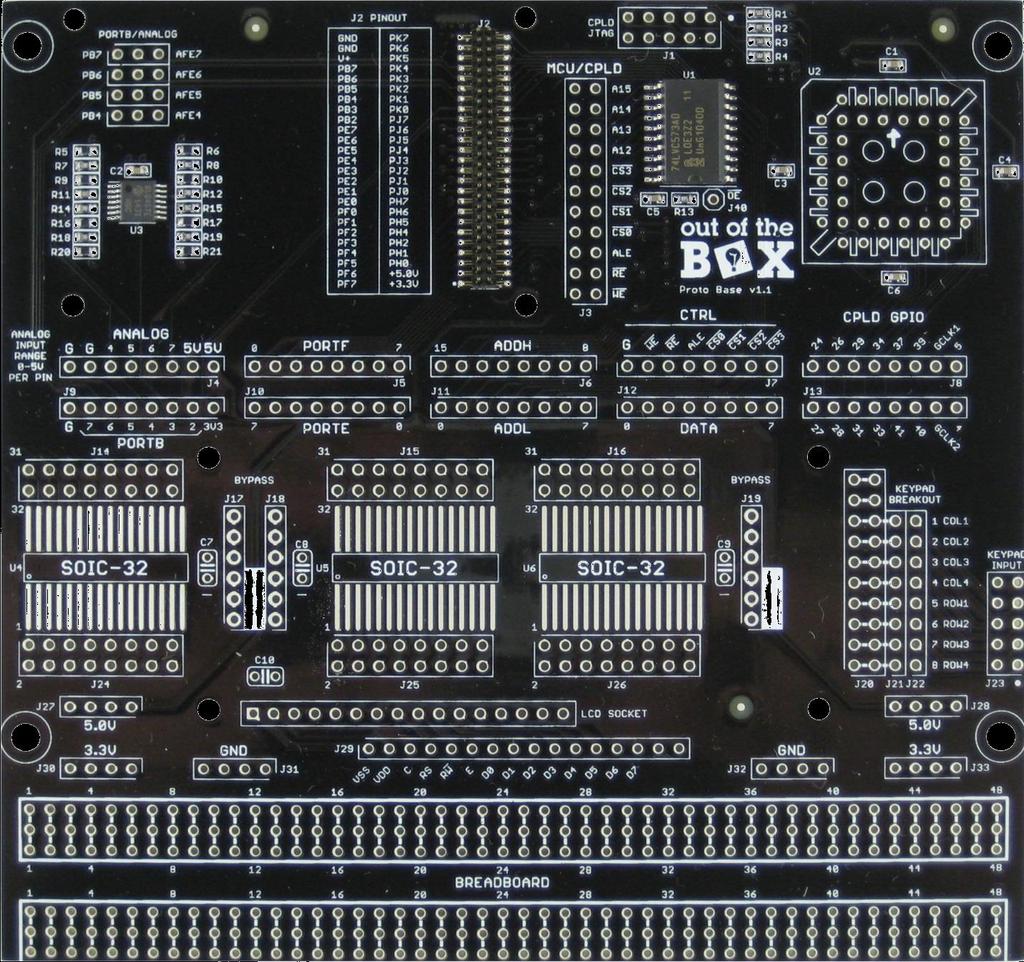
1 µpad Proto Base Assembly Guide Last Updated May 11, 2015
2 Table of Contents Required Tools... 5 Recommended Tools... 5 Assembly Procedure... 6 Step 1: Break Pin Headers to Size... 6 Table 1: Header Cut Reference... 6 Step 2: Soldering... 8 Step 2.01: Solder U Step 2.02: Solder J Step 2.03: Solder the ANALOG/PORTB selector Step 2.04: Solder J Step 2.05: Solder J Step : Solder J27, J28, J30, J31, J32, and J Step : Solder J17, J18, and J Step : Solder J4, J5, J6, J7, J8, J9, J10, J11, J12, and J Step : Solder J14, J15, J16, J24, J25, and J Step : Solder J20, J21, and J Step : Solder J1 and J2 of the Level Shifter Breakout Board Step 2.36: Solder the Keypad Cable Connection of the Keypad Breakout Board Step 2.37: Solder the Keypad Connection of the Breakout Board Step 3: Mounting the LCD Step 3.01: Affix Washers to Each of the LCD Mounting Screws Step 3.02: Insert LCD Header into the LCD Socket Step 3.03: Mount the LCD (Do Not Solder) Step 3.04: Solder the LCD Header and Socket Step 3.05: Solder J Step 4: Adding Components to the Breadboard Area Step 4.01-: Adding Breakout Headers for the Potentiometers Step 4.02: Add the LED Array Step 4.03: Add the 470 Ohm SIP Step 4.04: Add a 2.2K SIP Step 4.05: Add the DIP Switch... 29
3 Step 4.06: Add the Level Shifter Step 4.07: Add Breakout Headers for the Piezo Buzzer Step 4.08: Add the Piezo Buzzer Step 4.09: Add Wire Wrap-able Headers for the Level Shifter Step 4.10: Add a 10 Pin Header for the DIP Switch and LED Array Step 4.11: Add a Wire Wrap Header for the LED Array s Signals Step 4.12: Add a Wire Wrap Header for DIP Switch GND Connections Step 5: Mount Standoffs Appendix I: Additional Assembly Adding Shield Sockets to the µpad Appendix II: Parts List Kit Box Contents Additional Components Packaged With Boards Appendix III: Full Assembly References Figure 1: Board Assembly Full Top Figure 2: Board Assembly Full Bottom... 41
4
5 Required Tools 1. Flux Pen 2. Solder 3. Soldering Iron 4. Diagonal Cutters Recommended Tools 1. #1 Phillips Screwdriver 2. Nut driver 3/16 3. Needle Nose Pliers
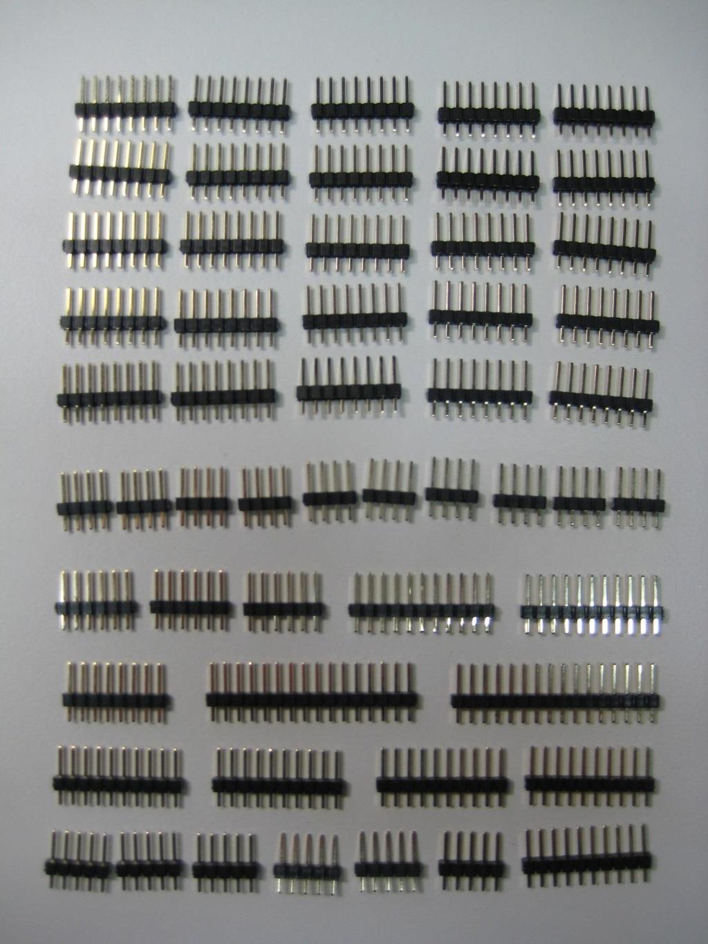
6 Assembly Procedure Step 1: Break Pin Headers to Size Table 1: Header Cut Reference Index Length 1 QTY Length 2 QTY n/a n/a n/a n/a n/a n/a n/a n/a n/a n/a n/a n/a n/a n/a
7
8 Step 2: Soldering When soldering in this procedure there is a mantra to follow Affix Flux Tack Check alignment Solder fully This is particularly important for pin headers since they can be misaligned causing issues in the future. This is why it is crucial for you to take your time and be diligent. It is fairly trivial to realign a header that is tacked in place, but realignment of a fully soldered header is very taxing. Likewise, be certain of which side a part is to be soldered upon before doing so. If you have any doubts whatsoever, please consult your TA who will be happy to help you.


9 Step 2.01: Solder U2 U2 is the 44 pin PLCC socket for a CPLD. Note the arrow orientation pictured in the top center of the CPLD socket. Apply flux to the pins shown soldered above. Then wet your iron with sufficient solder to tack the CPLD socket in place as shown. Before continuing make sure that the socket is seated flat on top of the board. If not, simply press down and apply heat to each of the tacked pins.


10 Solder all remaining CPLD socket pins. Step 2.02: Solder J1 J1 is the CPLD JTAG header used to program the CPLD. Place one of your 5 pin headers into a row of location J1 as shown above. Hold the header in place and apply flux to one of the outside pins of the header. Once fluxed, wet your iron with sufficient solder to tack the fluxed pin. If the header is aligned correctly it will appear perpendicular from the side as seen in the below image.


11 If the header is not aligned perpendicular to the surface as shown above, use your iron to reheat the tacked pin to adjust the alignment. Re-fluxing the pin may be beneficial. Once the header is aligned in a satisfactory manner, solder the rest of the remaining pins. Note: Consider retouching the solder connection to the pin you first tacked down if needed. Use your best judgement. You should now add and tack down the second row of headers to J1 as shown below.

12 The second row should be considerably easier to align perpendicular to the board surface by using the side of the first header. But, to be safe, you should still verify before soldering the rest of the pins. If you are satisfied with the alignment of the second header, complete the soldering of J1. Step 2.03: Solder the ANALOG/PORTB selector Unlike J1 this set of headers will be soldered on the opposite side of the board. Place one of your 4 pin headers as shown below. Note that when placed on the correct side of the board the label shown is ANALOG/PORTB. The other side of the board labels the header the opposite way. This is your check.


13 Once you have determined your header is placed correctly, flux and tack one of the pins as you have done before. Before soldering the rest of the header pins, determine whether the header is soldered sufficiently, i.e. it is perpendicular to the board. Doing so is particularly critical for this set of headers since they will be used with jumpers. So take caution before proceeding to solder the full row.

14 Next, solder the 2 nd and 3 rd rows of headers using the same procedure as before following the above mentioned mantra. Step 2.04: Solder J3 J3 is another connection used with jumpers. These pins are specifically used to connect External Bus Interface control lines of the µpad to the CPLD. Place one of your 11 pin headers as shown above, then follow the normal mantra. Affix Flux Tack Check alignment Solder fully Do the same with your other 11 pin header. Step 2.05: Solder J23 J23 is the keypad cable connection. All keypad signals are passed through this header.


15 Place one of your 5 pin headers as shown and mount it per the usual mantra. Then place the other header to complete the J23 connector.
 J32. This is the orientation these connectors should be soldered. Follow the mantra and solder all 6 of the connections. Step 2.")
16 Step : Solder J27, J28, J30, J31, J32, and J33 These connections are the primary power connections of the board. Shown above is J31. Note the placement orientation (side of board). The other side of the board displays the reference designator (REFDES) J32. This is the orientation these connectors should be soldered. Follow the mantra and solder all 6 of the connections. Step : Solder J17, J18, and J19 These connections are breakouts for the bypass capacitors that will be soldered later in the procedure. The bypass breakout headers allow for easily wiring of bypass caps to ICs. These headers are divided into a positive and negative section via bold white bars. The pins adjacent to the bars are the negative terminals, and the other pins are the positive terminals


17 Displayed above are J17 and J18. You can ensure your correct board side placement by the absence of the REFDES. These labels are only on the top of the board. Mount all three connectors in the manner displayed above. Step : Solder J4, J5, J6, J7, J8, J9, J10, J11, J12, and J13 These connections are breakouts of the µpad s and the CPLD s signals. Displayed above is J4. You can verify the side of the board this connector is located on by checking that the REFDES is not present. The other side of the board will label this connector with J4. Mount all the aforementioned connections with this board side orientation. Step : Solder J14, J15, J16, J24, J25, and J26 These are the breakout connections for the SOIC surface mount footprints.


18 Place one 8 pin header in each of the 6 connection locations. The below image depicts J15, J16, J25, and J26. Next mount the second row of headers, and solder them as per usual.

19 Step : Solder J20, J21, and J22 These connections are used for the keypad interface. J20 is designed to fit a 10 pin header and a 10 pin SIP resistor side by side. J22 is a linear breakout of all the Keypad signals coming from the keypad cable. J21 exists to allow for jumpers to be added to pull-up or pull down rows or columns of the keypad without additional wire wrapping. Pins without jumpers on J22 can then be connected to GPIO pins for reading data from the keypad. Install the headers exactly as displayed in the below image one row at a time. Starting with the 10 pin header of J20 is advisable. J21 and J22 will be fitted with 8 pin headers. Solder all of these headers as per usual. Step : Solder J1 and J2 of the Level Shifter Breakout Board This bi-directional level shifter will be used to level shift the Xmega data bus pins operating at 3.3V logic to 5V levels expected by the LCD. Without this device the Xmega pins would experience voltages beyond their recommended operating range.

20 Solder two 10 pin headers in the manner depicted in the below image. It is crucial that the pin headers attached to this breakout board are aligned perpendicular to the board surface. A trick for doing this perfectly is to insert the pins into the breadboard section of the µpad Proto Base, and then place the breakout board onto both of these headers. You can then solder the headers to the breakout board, while they are held by the breadboard. Note that in the image above the headers are only tacked in place. You will want to solder all of the pins once your alignment is verified.

21 Step 2.36: Solder the Keypad Cable Connection of the Keypad Breakout Board This connection organizes the keypad signals to best fit the keypad cable. Solder two 5 pin headers one at a time as depicted by the below image. Note the label TOP denoting which side of the breakout board is up. Step 2.37: Solder the Keypad Connection of the Breakout Board This connection will be soldered to the keypad directly in a step to follow. Mount an 8 pin header as depicted in the below image. Step 2.38: Solder Keypad

22 The keypad will be used to provide user input to the µpad. Solder the 8 pin header of the keypad breakout board directly to the keypad. Take care to mount the keypad flat against the plastic portion of the header. Another note: there are 10 holes in the keypad, but only the center 8 have electrical connections. Take care to place/solder the pins into the keypad correctly. Step : Solder C7, C8, C9, and C10 These are bypass capacitors for use with the three SOIC breakouts, and the LCD. Bypass capacitors serve to smooth out power signals to their respective devices. When a burst of current is drawn by a device, a power supply signal often drops in potential. Bypass capacitors such as these are used to field such bursts in current, therefore maintaining proper supply levels. Place each of the capacitors in their respective locations shown below. To hold these devices in place for soldering, the best practice is to bend the leads flat against the board.

23 Once soldered, you should use a diagonal cutter to snip the leads off the capacitors. Step 3: Mounting the LCD The µpad Proto Base is designed to interface directly to the LCD provided in your kit. So precisely, in fact, that it is crucial to fit the LCD and connectors to one another prior to soldering anything. The following instruction will guide you: Step 3.01: Affix Washers to Each of the LCD Mounting Screws. The reason for these washers is to prevent dissimilar metal corrosion between the mounting screws and the LCD. Thread a washer all the way up to the head of each of the mounting screws. Step 3.02: Insert LCD Header into the LCD Socket The header, in a later step, will be soldered directly to the LCD, and the socket, again at a later step, will be soldered to the µpad Proto Base. Insert one of your 16 pin headers into the 16 pin LCD socket. Step 3.03: Mount the LCD (Do Not Solder) Though not required, this step is most easily performed with a #1 Phillips screwdriver, and a nut driver or a pair of Needle Nose Pliers. Place the LCD header/socket from the previous step in place and screw the LCD to the µpad Proto Base. The proper stack-up for the LCD is; screw, washer; LCD; spacer; µpad Proto Base; and lastly, a nut.


24 LCD mounted mechanically as viewed from above. Notice the LCD header pins poke through the LCD s board connections. LCD mounted mechanically as viewed from below. Notice the LCD socket pins poke through the LCD socket connections of the µpad Proto Base.

25 Step 3.04: Solder the LCD Header and Socket In the last step the LCD was aligned and mechanically affixed to the µpad Proto Base. Once the mechanical mounting is verified to be snug, the LCD header and socket should be soldered. LCD mounted and soldered, as viewed from above. Step 3.05: Solder J29 J29 is the wire wrap-able header containing all of the LCD signals. Mount and solder your last 16 pin header to location J29 on the µpad Proto Base.


26 Step 4: Adding Components to the Breadboard Area Step 4.01-: Adding Breakout Headers for the Potentiometers In step one, ten of the twelve 40 pin headers were broken apart, which means that two of the headers remain intact. For this step, break off two 3 pin headers from a pristine forty pin header. Mount these two 3 pin headers as shown below. Next, mount the potentiometers above these headers as shown below.


27 Step 4.02: Add the LED Array Place the LED array as shown below. The side of the array with text upon it should be facing the LCD. Once the orientation of the LED array has been verified, solder it in place. Step 4.03: Add the 470 Ohm SIP Place the SIP as the pictures below depict. Note the Common indicator is located on the pin just left of the LED Array in this view.


28 The above image is provided to further illustrate the mounting location of the SIP. Once the location is verified, solder the SIP in place. Step 4.04: Add a 2.2K SIP Place the SIP in the location depicted in the picture below. Note that the common of the 2.2K SIP is located adjacent to the 470 Ohm SIP. Once the location and orientation of the SIP is verified, solder the SIP in place.


29 Step 4.05: Add the DIP Switch Use the following photos as a reference for mounting the DIP switch to the proto area. The picture above depicts the pin alignment of the DIP switch. Notice that switch 1 s pin is located adjacent, not in line with the common of the 2.2K SIP. The picture above further depicts the alignment of the DIP switch.


30 Step 4.06: Add the Level Shifter Insert and solder the level shifter as displayed below. Step 4.07: Add Breakout Headers for the Piezo Buzzer Break off another 3 pin header, and mount it to the location depicted in the below image.

31 Step 4.08: Add the Piezo Buzzer Align the piezo buzzer as shown in the picture below. Note the picture above depicts a space between the board and the buzzer. This is simply to further illustrate the location of the buzzer. When you mount your buzzer, the device should not have this space. Solder the buzzer. Using a pair of diagonal cutters snip off the excess of the buzzer pins.

32 Step 4.09: Add Wire Wrap-able Headers for the Level Shifter In order to easily wire wrap to the level shifter breakout board s signals, the two remaining 10 pin headers will be used. Mount the headers directly beside the breakout board s pins. One side of the breakout board, and its wire wrap header, is displayed below.


33 Step 4.10: Add a 10 Pin Header for the DIP Switch and LED Array This header serves multiple purposes. This header is a means of wire wrapping to the commons of the 470 Ohm SIP, and the 2.2K SIP. Additionally, this SIP exposes the DIP switch signals intended to be connected to the µpad s I/O pins. Use the above image as a reference of where the headers should be soldered. Step 4.11: Add a Wire Wrap Header for the LED Array s Signals Use an 8 pin header to make 8 LED signals accessible via wire wrap. Mount the pin header in the location depicted by the following picture.

34 Step 4.12: Add a Wire Wrap Header for DIP Switch GND Connections Use an 8 pin header and mount it as shown below. The pins need to be in line with the DIP switch s individual switches.
35 Step 5: Mount Standoffs Screw the 4 metal standoffs provided to the µpad Proto Base.

36 Appendix I: Additional Assembly Adding Shield Sockets to the µpad Included in the kit for the µpad Proto Base are four 8 pin sockets. These sockets are the µpad Shield Sockets. These sockets solder onto the µpad as shown below.
37 Appendix II: Parts List Kit Box Contents Index QTY Description 1 4 LCD Spacers (9MM) 2 4 LCD Screws (3/4 ) 3 4 LCD Nuts 4 4 LCD Washers 5 3 RES 10K OHM 1/4W 1% AXIAL AHC k Pot 8 1 Piezo Buzzer 9 2 RES ARRAY 2.2K OHM 9 RES 10SIP 10 1 Resistor Networks & Arrays 10pins 470ohms Bussed AHC RECEIVER IR REM CTRL 3V 40KHZ Jumpers 14 1 DIP Switch 15 1 LED Array 16 1 IC SRAM 256KBIT 45NS 28SOP 17 1 LCD Socket 18 4 µpad Shield Sockets 19 1 Keypad 20 1 LCD 21 1 Level Shifter Breakout Board
38 22 1 Keypad Cable X40 Pin Headers 24 1 Wire Wrap Tool 25 1 CPLD socket
39 Additional Components Packaged With Boards Index QTY Description 1 1 USB Cable 2 4 µpad Spacers (7MM) 3 4 µpad Screws (9/16") 4 4 µpad Nuts 5 4 Proto Base Standoffs 1/2" 6 4 Proto Base Standoff Screws

40 Appendix III: Full Assembly References Figure 1: Board Assembly Full Top

41 Figure 2: Board Assembly Full Bottom
UF-3701 Power Board Construction Guide
 Page 1/5 Soldering and Part Placement See the Chapter 3 of the MIT 6270 Manual for information on electronic assembly, including soldering techniques and component mounting. Construction Information All
RC Tractor Guy Controller V2.1 Assembly Guide
 RC Tractor Guy Controller V. Assembly Guide Features 0 Push button inputs Dual axis thumb sticks with built-in push button Rotary encoders with built-in push button MCU Socket to suit Meduino Mega 560
University of Florida EEL 4744 Drs. Eric M. Schwartz, Karl Gugel & Tao Li Department of Electrical and Computer Engineering
 Page 1/9 Revision 1 OBJECTIVES In this document you will learn how to solder and to debug a board as you are building it. REQUIRED MATERIALS Website documents o UF 68HC12 Development Board Manual (board
MAIN PCB (The small one)
") THANKS FOR CHOOSING ONE OF OUR KITS! This manual has been written taking into account the common issues that we often find people experience in our workshops. The order in which the components are placed
THANKS FOR CHOOSING ONE OF OUR KITS! This manual has been written taking into account the common issues that we often find people experience in our workshops. The order in which the components are placed
A Backlighted LCD for your K1
 A Backlighted LCD for your K1 (K1BKLTKIT) Tom Hammond - NØSS, July 27, 2006 Rev C Thanks to Wayne Burdick, N6KR for suggesting this implementation of backlighting the K1 display. APPLICABILITY This modification
Phi -1 shield Documentation. Table of content
 Phi -1 shield Documentation Last reviewed on 01/03/11 John Liu Table of content 1. Introduction: 2 2. List of functions: 2 3. List of possible projects: 2 4. Parts list: 3 5. Shield pin usage: 3 6. List
Tubbutec Sumtiple Kit Version Construction Manual
 Tubbutec Sumtiple Kit Version Construction Manual This document describes the construction of the Sumtiple Kit. The following parts are included: 1x Sumtiple PCB with SMD-Parts already soldered 1x Front
4.1 Parts and Components... IV Assembly Tips... IV Assembly Precautions... IV Required Tools, Equipment and Materials..
 IV PERSONALITY MODULE ASSEMBLY 4.1 Parts and Components............ IV-1 4.2 Assembly Tips............... IV-1 4.3 Assembly Precautions............ IV-1 4.4 Required Tools, Equipment and Materials.. IV-1
PARTS LIST 1 x PC Board 36 x 5mm Red LED 36 x 12mm LED Standoff 36 x NPN Transistor 36 x 10kΩ Resistor OTHER PARTS YOU MAY NEED
 PARTS LIST 1 x PC Board 36 x 5mm Red LED 36 x 12mm LED Standoff 36 x NPN Transistor 36 x 150Ω Resistor 36 x 10kΩ Resistor 17 x Mini Toggle on-off 8 x Mini Toggle (on)-off-(on) 1 x 470Ω Resistor 1 x 47µF
Lab 0: Wire Wrapping Project: Counter Board
 Lab 0: Wire Wrapping Project: Counter Board September 3, 2008 In this experiment, you will build a simple counter circuit that can be plugged into your breadboard. It will provide a set of TTL output signals
PiRyte Mini ATX PSU Revision User Manual
 Revision 1.1.0 User Manual Overview Congratulations on your purchase of the PiRyte Mini ATX PSU! Please read this entire manual before using to ensure you receive maximum benefit from this board while
BMC24. MIDI TO GATE CONVERTER DOCUMENTATION. This documentation is for use with the "Euro Style" bottom board.
 BMC24. MIDI TO GATE CONVERTER DOCUMENTATION. This documentation is for use with the "Euro Style" bottom board. A. USING THE MIDI TO GATE CONVERTER B. PARTS LIST C. BUILDING INSTRUCTIONS D. SCHEMATICS Revision.
Bill of Materials: Picaxe-based IR Control Module Pair PART NO
 Picaxe-based IR Control Module Pair PART NO. 2171014 The IRGEII is an IR (Infra Red) Transmitter and Receiver pair that uses a 38 KHZ frequency of invisible light to communicate simple instructions. The
PiRyte Mini ATX PSU Revision 1.0 User Manual
 Revision 1.0 User Manual Overview Congratulations on your purchase of the PiRyte Mini ATX PSU! Please read this entire manual before using to ensure you receive maximum benefit from this board while protecting
Assembly Guide. LEDs. With these assembly instructions, you can easily build your own SWT16. All required components are included in this kit.
 Assembly Guide With these assembly instructions, you can easily build your own SWT16. All required components are included in this kit. You need the following tools: soldering iron, wire cutter and solder.
The Basic Counter. Hobby Electronics Soldering Kit. Instruction Guide
 The Basic Counter Hobby Electronics Soldering Kit Instruction Guide TM For the best outcome, follow each step in order. We recommend reading this guide entirely before you get started. Tools required:
KDR00101 DMX Controlled Relay Kit
 KDR00101 DMX Controlled Relay Kit This is a DMX512-A relay kit using ANSI approved RJ-45 connectors for DMX networks. Power requirements are 12 Vdc @ 100 ma. The relay contact rating is 10 Amp @ 120 or
Building the VMW Time Circuitry Meter by Vincent M. Weaver 6 May 2014
 Building the VMW Time Circuitry Meter http://www.deater.net/weave/vmwprod/hardware/time_circuit/ by Vincent M. Weaver 6 May 2014 1 Introduction This is a work in progress. I will update it as I complete
EQ573 Assembly guide. EQ573 Assembly guide Main board 1. Diodes. 2. Resistors (1) 3. Test pins. 4. Ceramic capacitors.
 3. Test pins. 4. Ceramic capacitors.") EQ573 Assembly guide Safety warning The kits are main powered and use potentially lethal voltages. Under no circumstance should someone undertake the realisation of a kit unless he has full knowledge about
EQ573 Assembly guide Safety warning The kits are main powered and use potentially lethal voltages. Under no circumstance should someone undertake the realisation of a kit unless he has full knowledge about
KDR00301 DMX Controlled Relay Kit
 KDR00301 DMX Controlled Relay Kit This is a DMX512-A relay kit using ANSI approved RJ-45 connectors for DMX networks. Power requirements are 12 Vdc @ 200 ma. The relay contact rating is 10 Amp @ 120 or
Pacific Antenna Two Tone Generator
 Pacific Antenna Two Tone Generator Description Our Two Tone Generator kit provides two non-harmonic, sine wave signals for testing audio circuits Outputs of approximately 700Hz and 1900Hz and the combination
edrive RAM Battery Alternate Replacement Procedure
 edrive RAM Battery Summary This technical note describes the process for replacing the TINI RAM battery with a higher capacity battery. With the edrive turned on, the external battery can be changed without
Quicksilver 606 TR-606 CPU Upgrade
 Quicksilver 606 TR-606 CPU Upgrade D650C 128 Installation Guide Social Entropy Electronic Music Instruments TABLE OF CONTENTS WARNINGS... 1 OVERVIEW... 2 WHAT'S IN THE BOX... 3 OPENING THE TR-606 CASE...
Assembling the Printed Circuit Board for the EDE1200 Robot
 This board receives instructions from either a CBL2, a LabPro or (with an adapter cable) an original CBL. The board has two 595 shift registers (each providing 8 bits of on-board memory) and two EDE1200
Teensy 3.5/3.6 Breakout (Revision A, Standard)
") Teensy 3.5/3.6 Breakout (Revision A, Standard) This is a breakout for the Teensy 3.5 and Teensy 3.6 development boards by PJRC. Included are all the pin headers you need to assemble it, a switch to select
Teensy 3.5/3.6 Breakout (Revision A, Standard) This is a breakout for the Teensy 3.5 and Teensy 3.6 development boards by PJRC. Included are all the pin headers you need to assemble it, a switch to select
Pacific Antenna Easy TR Switch Kit
 Pacific Antenna Easy TR Switch Kit Kit Description The Easy TR Switch is an RF sensing circuit with a double pole double throw relay that can be used to automatically switch an antenna between a separate
KDS Channel DMX Controlled Servo Kit
 KDS00801 8-Channel DMX Controlled Servo Kit This is a DMX512-A controlled servo kit using ANSI approved RJ-45 connectors for DMX networks. Power requirements are 8-20 VDC @ 50 ma. The board features an
7 8 9 C. PRELAB REQUIREMENTS You must adhere to the Lab Rules and Policies document for every lab.
 Page 1/ Revision 1 OBJECTIVES To understand how a keypad functions as a raster scan input device and to learn how to interface a keypad to a microprocessor. Further explore and understand the implementation
BS2p40tm OEM Module. Surface mount/through hole kit By Robert L. Doerr. Manual Revision.5
 BS2p40tm OEM Module Surface mount/through hole kit 2006 By Robert L. Doerr Manual Revision.5 NOTE: The BASIC Stamp and the BS2p40 and Interpreter chip are trademarks of Parallax. This partial kit allows
dual bipolar voltage controlled step sequencer DIY ASSEMBLY MANUAL v1.03
 dual bipolar voltage controlled step sequencer DIY ASSEMBLY MANUAL v1.03 Contents Contents... 2 Introduction... 3 Part Sourcing Notes for Non Kit Builders... 3 Eurorack Kit Assembly... 4 Resistors and
Arduino Robots Robot Kit Parts List
 Arduino Robots Robot Kit Parts List (1) Metal Chassis (2) Push Button Activators (2) Servo Motors w/ Cross Wheels (2) IR Receivers (1) Control Board (1) Piezo Speaker (1) Dual-Sided Screwdriver (1) Cotter
MAIN PCB (The small one with the square cut out from one side)
") THANKS FOR CHOOSING ONE OF OUR KITS! This manual has been written taking into account the common issues that we often find people experience in our workshops. The order in which the components are placed
THANKS FOR CHOOSING ONE OF OUR KITS! This manual has been written taking into account the common issues that we often find people experience in our workshops. The order in which the components are placed
Effects Loop Installation Guide
 Warnings and Disclaimer Effects Loop Installation Guide You will be working with HIGH VOLTAGE. These voltages CAN BE DEADLY if you are not extremely careful. If you are not comfortable working with HIGH
Post Tenebras Lab. Written By: Post Tenebras Lab
 Post Tenebras Lab PTL-ino is an Arduino comptaible board, made entirely out of through-hole components. It is a perfect project to learn how to solder and start getting into the world of micro controllers.
RC-210 Repeater Controller Assembly Manual
 Arcom Communications 24035 NE Butteville Rd Aurora, Oregon 97002 (503) 678-6182 arcom@ah6le.net RC-210 Repeater Controller Assembly Manual Hardware Version 3.0 Original Release Date September 13, 2004
Lab3: I/O Port Expansion
 Page 1/6 Revision 0 26-Jan-16 OBJECTIVES Explore and understand the implementation of memory-mapped I/O. Add an 8-bit input port and an 8-bit output port. REQUIRED MATERIALS EEL 3744 (upad and upad Proto
Phase Loss Protection Upgrade. Phase Loss Protection Upgrade. In this bulletin:
 Phase Loss Protection Upgrade In this bulletin: Introduction... 2 Purpose... 2 General... 2 Applicability... 2 HD3070 Phase Loss Protection Upgrade Kit Parts... 2 Preparation... 4 Install the Phase Loss
GEKCO MODEL CLK036 DIGITAL CLOCK ASSEMBLY & OPERATION MANUAL. GEKCO Inc SW Cypress Ln McMinnville, OR (503) P/N REV 1.
 P/N REV 1.") GEKCO MODEL CLK036 DIGITAL CLOCK ASSEMBLY & OPERATION MANUAL GEKCO Inc. 1565 SW Cypress Ln McMinnville, OR 97128 (503) 472-4770 P/N 595-324 REV 1.0 Copyright c 2018 GEKCO Inc. All Rights Reserved Printed
GEKCO MODEL CLK036 DIGITAL CLOCK ASSEMBLY & OPERATION MANUAL GEKCO Inc. 1565 SW Cypress Ln McMinnville, OR 97128 (503) 472-4770 P/N 595-324 REV 1.0 Copyright c 2018 GEKCO Inc. All Rights Reserved Printed
GEKCO MODEL CLK056 DIGITAL CLOCK ASSEMBLY & OPERATION MANUAL GEKCO
 GEKCO MODEL CLK056 DIGITAL CLOCK ASSEMBLY & OPERATION MANUAL GEKCO Inc. 1565 SW Cypress Ln McMinnville, OR 97128 (503) 472-4770 P/N 595-325 REV 181030 Copyright c 2018 GEKCO Inc. All Rights Reserved Printed
Wind Logger Shield. Parts included: Date: 29/07/14 Version: 1.0 By: Matt Little
 Wind Logger Shield Date: 29/07/14 Version: 1.0 By: Matt Little Parts included: This is a simple shield to easily implement a wind resource data logging system. It is designed to read 2 x pulse type anemometers
[Note: Power adapter is not included in the kits. Users need to prepare a 9 12 V ( >300mA capacity ) DC power supply]
![[Note: Power adapter is not included in the kits. Users need to prepare a 9 12 V ( >300mA capacity ) DC power supply]](/thumbs/76/74094055.jpg "[Note: Power adapter is not included in the kits. Users need to prepare a 9 12 V ( >300mA capacity ) DC power supply]") 062 LCD Oscilloscope Assembly Notes Applicable Models: 06203KP, 06204KP DN062-18v02 Important Notes 1. Some components shown in the schematic and PCB layout are for options or adjustments. They do not
062 LCD Oscilloscope Assembly Notes Applicable Models: 06203KP, 06204KP DN062-18v02 Important Notes 1. Some components shown in the schematic and PCB layout are for options or adjustments. They do not
How to Assemble a Desktop PC
 How to Assemble a Desktop PC By Taylor Koch iii Table of Contents Introduction to Building a Desktop PC... 1 Preparation and Precautions... 3 PC Parts... 3 Basic Tools... 3 Safety Precautions... 3 Installing
Installation/assembly manual for DCC/Power shield
 Installation/assembly manual for DCC/Power shield The DCC circuit consists of the following components: R1/R6 R2/R3 R4/R5 D1 C2 2 kω resistor ½ Watt (colour code Red/Black/Black/Brown/Brown) 10 kω resistor
Installation Guide. Retrofit Kit for USB Ready Intraoral Systems
 Installation Guide Retrofit Kit for USB Ready Intraoral Systems Table of Contents Wall-Mount Retrofit Kit... 2 Introduction... 2 Connecting the Articulating and Horizontal Arm Cables... 2 Installing the
*on-board power supply capability limited. External battery should be used for higher power servos.
 Pan and Tilt Decoder II PART NO. Add affordable Pan and Tilt control to your security cameras using the Pan and Tilt Decoder II and the DFRobot DF05BB Tilt/Pan Kit (5kg), Jameco PN 2144518 or the DAGU
Phi-panel backpack assembly and keypad options Dr. John Liu 12/16/2012
 Phi-panel backpack assembly and keypad options Dr. John Liu 12/16/2012 1. Introduction:... 3 Currently available:... 3 2. Backpack assembly... 4 3. Connecting to a keypad... 6 4. Rotary encoder keypads...
K8099 NIXIE CLOCK. * optional enclosure TKOK19 (black) - TKOK17 (white) ** optional plexiglass enlcosure B8099 ILLUSTRATED ASSEMBLY MANUAL
 - TKOK17 (white) ** optional plexiglass enlcosure B8099 ILLUSTRATED ASSEMBLY MANUAL") Total solder points: 230 + 74 Difficulty level: beginner 1 2 3 4 5 advanced NIXIE CLOCK K8099 ** * A unique combination of both vintage and modern electronics ILLUSTRATED ASSEMBLY MANUAL H8099IP-1 * optional
Total solder points: 230 + 74 Difficulty level: beginner 1 2 3 4 5 advanced NIXIE CLOCK K8099 ** * A unique combination of both vintage and modern electronics ILLUSTRATED ASSEMBLY MANUAL H8099IP-1 * optional
Bill of Materials: Turn Off the Lights Reminder PART NO
 Turn Off the Lights Reminder PART NO. 2209650 Have you ever woke up early in the morning to find out that the kids (or adults) in your home forgot to turn off the lights? I've had that happen a number
Plasma Panel Replacement Guide DU-42PX12X
 Plasma Panel Replacement Guide DU-42PX12X Panel Replacement: At this point, the panel has been determined to be defective and replacement is necessary. Upon receiving the replacement panel, it must be
15 Channel IR transmitter. Total solder points: 53 Difficulty level: beginner advanced K8049 ILLUSTRATED ASSEMBLY MANUAL
 15 Channel IR transmitter Compatible with most Velleman IR receiver kits, 4 adresses allow the use of multiple receivers in one room. Total solder points: 53 Difficulty level: beginner 1 2 3 4 5 advanced
SM010, Assembly Manual PCB Version 1.0
 180 SM010, Assembly Manual MATRIXARCHATE 16 8 IO SEQUENTIAL MATRIX SIGNAL ROUTER SM010 1 2 1 2 3 4 5 3 4 5 6 7 8 9 10 11 12 6 7 8 9 10 11 12 13 14 15 16 PROGRAM A B C D E F G H f1 f2 20.000 180 SSSR Labs
Universal Keying Adapter 3+
 Universal Keying Adapter 3+ The Universal Keying Adapter Version 3+ kit will allow you to key nearly any transmitter or transceiver with a straight key, electronic keyer, computer serial or parallel port
Rapid28iXL PIC Prototyping PCB User Manual
 Description Features This is a PCB designed to facilitate the rapid prototyping of a device based on a 28 pin Microchip PIC microcontroller. To allow users to focus on their application, we take care of
Section 5: Installing Parts from the Controls and Connectors Bag
 Section 5: Installing Parts from the Controls and Connectors Bag 1) Install Pinheaders & Sockets Using the Component Layout Diagram in Appendix A as a guide, install all pinheaders and strip sockets on
Rapid40iXL PIC Prototyping PCB User Manual
 Description This is a PCB designed to facilitate the rapid prototyping of a device based on a 40 pin Microchip PIC microcontroller. To allow users to focus on their application, we take care of key housekeeping
Button Code Kit. Assembly Instructions and User Guide. Single Button Code Entry System
 Button Code Kit Single Button Code Entry System Assembly Instructions and User Guide Rev 1.0 December 2009 www.alan-parekh.com Copyright 2009 Alan Electronic Projects Inc. 1. Introduction... 4 1.1 Concept
AVR-M Rev 5 ASSEMBLY
 AVR-M Rev 5 ASSEMBLY The AVR_M is a very compact self contained Atmel AVR mcu controller board. It includes an onboard serial programmer (via PC com port), an I2C eeprom and can use a Mega163, Mega16 or
Rapid40i PIC Prototyping PCB User Manual
 Description This is a PCB designed to facilitate the rapid prototyping of a device based on a 40 pin Microchip PIC microcontroller. To allow users to focus on their application, we take care of key housekeeping
QRPometer Assembly Manual Copyright 2012 David Cripe NM0S The 4 State QRP Group. Introduction
 QRPometer Assembly Manual Copyright 2012 David Cripe NM0S The 4 State QRP Group Introduction Thank you for purchasing a QRPometer. We hope you will enjoy building it and and find it a useful addition to
Raspberry-Pi Shield: Binary-Coded-Decimal Clock
 Raspberry-Pi Shield: Binary-Coded-Decimal Clock ASSEMBLY INSTRUCTIONS What is it? This kit builds a binary-coded-decimal clock, driven by a Raspberry-Pi (which should be mounted on the back). This is a
TIME WIZARD MULTI CLOCK DIVIDER BUILDING GUIDE
 TIME WIZARD MULTI CLOCK DIVIDER BUILDING GUIDE Table of Contents 0. Components List + Tools 0. PCB Sides 03. PCB Assembly 04_. Diode N448 04_. Laying Resistors 04_3. Capacitors 04_4. Quartz 04_5. 78L05
Assembly Instructions for the KA Electronics Elliptic Equalizer
 Assembly Instructions for the KA Electronics Elliptic Equalizer Install IC sockets Elliptic Equalizer PC Board Stuffing Guide Place the PC Board on the work bench silkscreen side face up. Place twelve
IQ32 Upgrade Kit Assembly Instructions
 IQ32 Upgrade Kit Assembly Instructions Jim Veatch WA2EUJ September 17, 2018 TABLE OF CONTENTS 1. INTRODUCTION... 3 2. IQ-32 UPGRADE KIT INVENTORY... 4 3. PREPARING THE RS-HFIQ AND SIDE PANELS... 6 4. CONNECTING
Celadon, Inc. TRX Series Infrared Remote and Receiver Assembly and Operation Instruction Manual
 Celadon, Inc. TRX Series Infrared Remote and Receiver Assembly and Operation Instruction Manual REV 2.1 COPYRIGHT 2001 I. Introduction Thank you for purchasing your infrared remote control transmitter
AXE Stack 18. BASIC-Programmable Microcontroller Kit. An inexpensive introduction to microcontroller technology for all ability levels
 Ltd AXE Stack 18 BASIC-Programmable Microcontroller Kit a division of An inexpensive introduction to microcontroller technology for all ability levels Free Windows interface software Programmable in BASIC
Assembly Instructions for the KA Electronics IGFO Input Gain Filter Output Board
 Assembly Instructions for the KA Electronics IGFO Input Gain Filter Output Board IGFO PC Board Stuffing Guide Install IC sockets Place the PC Board on the work bench silkscreen side face up. Place ten
Q2 XBee Handheld Controller Assembly Guide
 Q2 XBee Handheld Controller Assembly Guide Copyright Quantum Robotics Inc. Q2 Controller V1.0 1 Parts List: The kit comes with 14 individual bags. 1. Case Top and Bottom 2. Case Screw Package containing:
Shack Clock kit. U3S Rev 2 PCB 1. Introduction
 Shack Clock kit U3S Rev 2 PCB 1. Introduction Thank you for purchasing the QRP Labs Shack Clock kit. This clock uses the Ultimate3S QRSS/WSPR kit hardware, but a different firmware version. It can be used
Pandora Assembly Instructions With Diamond Systems PC/104 CPUs (Athena, Elektra and Prometheus) November, 2006
 November, 2006") Pandora Assembly Instructions With Diamond Systems PC/104 CPUs (Athena, Elektra and Prometheus) November, 2006 Diamond Systems Corp. (650) 810-2500 www.diamondsystems.com This document describes how to
Pandora Assembly Instructions With Diamond Systems PC/104 CPUs (Athena, Elektra and Prometheus) November, 2006 Diamond Systems Corp. (650) 810-2500 www.diamondsystems.com This document describes how to
OpenSprinkler v2.1u Build Instructions
 OpenSprinkler v2.1u Build Instructions (Note: all images below are 'clickable', in order for you to see the full-resolution details. ) Part 0: Parts Check Part 1: Soldering Part 2: Testing Part 3: Enclosure
OpenSprinkler v2.2u Build Instructions
 OpenSprinkler v2.2u Build Instructions (Note: all images below are 'clickable', in order for you to see the full-resolution details. ) Part 0: Parts Check Part 1: Soldering Part 2: Testing Part 3: Enclosure
Part 2: Building the Controller Board
 v3.01, June 2018 1 Part 2: Building the Controller Board Congratulations for making it this far! The controller board uses smaller components than the wing boards, which believe it or not, means that everything
Building the FlipChip Tester
 Building the FlipChip Tester 1. Assembly of the Core Board You will need a fine low-wattage soldering iron and a Voltmeter. Take your time to solder the components on the Core Board. Better to spend a
DPScope SE Assembly Guide
 DPScope SE Assembly Guide Version 1.0 (Jan. 26, 2012) Congratulations for purchasing the DPScope SE oscilloscope kit! This guide will lead you through all the steps required to put it together so you ll
3 pyro output datalogger altimeter with an ATmega 328 microcontroller Kit assembly instructions
 3 pyro output datalogger altimeter with an ATmega 328 microcontroller Kit assembly instructions Version date Author Comments 1.0 29/05/2013 Boris du Reau Initial version Rocket Type Micro-max Model Mid
KAA Watt x 2 Class-D Audio Amplifier Kit
 KAA10021 50 Watt x 2 Class-D Audio Amplifier Kit This amplifier kit uses Texas Instruments TPA3116D2 stereo audio amplifier IC for driving speakers up to 50 watts @ 4 ohm per channel in stereo mode and
Installing PRO/DGX or Pro Soloist MIDI interface. R Grieb 9/08/2017
 Installing PRO/DGX or Pro Soloist MIDI interface. R Grieb 9/08/2017 Please read these instructions before purchasing the MIDI interface, to make sure you are comfortable performing the necessary steps.
Manual Version March 2007
 Manual Version 1.1 - March 2007 Page 1 Table of Contents Section1: 6922 Line Board Build... 3 6922 Line Board Version Notes... 5 6922 Line Board Build - HARD-WIRED VERSION... 5 Final Connections and Checks
Assembly of the TACOS WAT-910BD Housing v2
 1) Circuit Diagram 2) Assembly of PCB a)tools Required. Only simple hand tools are necessary to complete the assembly of the PCB. - Soldering Iron and solder - Needle nose pliers - Wire clippers/trimmers
CP5176 Assembly guide. Soldering. CP5176 Assembly guide Main PCB PCB split. Document revision 2.1 Last modification : 12/11/17
 CP5176 Assembly guide Safety warning The kits are main powered and use potentially lethal voltages. Under no circumstance should someone undertake the realisation of a kit unless he has full knowledge
Assembly Instructions for the KA Electronics RIAA EQ Monitor Switcher
 Assembly Instructions for the KA Electronics RIAA EQ Monitor Switcher Install IC sockets EQ Monitor Switcher PC Board Stuffing Guide Place the PC Board on the bench silkscreen side face up. Drop eleven
Bill of Materials: 8x8 LED Matrix Driver Game PART NO
 8x8 LED Matrix Driver Game PART NO. 2171031 This Game Maker II kit is a game design platform using a single color 8x8 matrix LED without the need for a shift register or expensive Arduino. The kit includes
ASSET LGA1366 Top-side Probe
 ASSET LGA1366 Top-side Probe (Manual version 1.1) For gaining test access to the debug port of Intel processors that are designed for use in LGA1366 Sockets (Socket B). These include the Intel Core i7
RC210 Repeater Controller Assembly Manual
 Arcom Communications 24035 NE Butteville Rd Aurora, Oregon 97002 (503) 678-6182 arcom@ah6le.net http://www.arcomcontrollers.com/ RC210 Repeater Controller Assembly Manual Hardware Version 3.3 Reproduction
Cutter Option Installation Instructions
 This kit includes the parts and documentation necessary to install the cutter option on the Zebra XiII, XiIII, and XiIIIPlus-Series printers. NOTE: The Cutter Option is not available for the 96XiIII. Adding
Lab3: I/O Port Expansion
 Page 1/5 Revision 2 6-Oct-15 OBJECTIVES Explore and understand the implementation of memory-mapped I/O. Add an 8-bit input port and an 8-bit output port. REQUIRED MATERIALS EEL 3744 (upad and upad Proto
TACH-ROTOR ADAPTER PLUS
 The Tach-Rotor Adapter Plus (TRA PLUS) works with 3-wire 12VDC fans commonly found in computers, computer power supplies, uninterruptable power supplies, DVRs, servers, and other electrical equipment with
You need the following components to assemble the Black n Wood Nixie Clock circuit board:
 You need the following components to assemble the Black n Wood Nixie Clock circuit board: Quantity Designator Description 1 Battery Battery, CR1220 1 Battery Battery holder 3 Button 1, Button 2, Button
DMX CONTROLLED RELAY K8072
 Total solder points: 167 Difficulty level: beginner 1 2 3 4 5 advanced DMX CONTROLLED RELAY K8072 f the means o ol. y b y la a re 2 protoc Control DMX51 wn well-kno ILLUSTRATED ASSEMBLY MANUAL Total solder
Elecraft K3 KPA3 Power Connector Replacement Revision B, June 30, 2017 Copyright 2017, Elecraft, Inc. All Rights Reserved
 Introduction Elecraft K3 KPA3 Power Connector Replacement Revision B, June 30, 2017 Copyright 2017, Elecraft, Inc. All Rights Reserved The connectors furnishing high current to the KPA3 module have failed
NewScope-7B Operating Manual
 2016 SIMMCONN Labs, LLC All rights reserved NewScope-7B Operating Manual Preliminary May 13, 2017 NewScope-7B Operating Manual 1 Introduction... 3 1.1 Kit compatibility... 3 2 Initial Inspection... 4 3
USB Stamp Adapter Board
 User Manual Engineering» Design» Product Blue Wolf, Inc. 9179 W. State Street Garden City, ID 83714 Revision History Version # Release Date Revision/Release Comments 1.0 3/7/2011 Initial draft for release.
Bill of Materials: Programming Interface for AVR PART NO
 Programming Interface for AVR PART NO. 2174664 "Programmers" for the AVR family of microcontrollers actually terminate in a 6-pin header socket, with no convenient means to directly connect to the chip
BuffaloLabs WiFi Lantern Assembly guide version 1
 BuffaloLabs WiFi Lantern Assembly guide version 1 Needed equipment: Solder iron Solder wire Cutter Wire stripper (optional) Hot glue gun Overview of the components (not including USB cable and box panels)
Emax SE SCSI Port Emax Plus Retrofit Instructions (Fl360)
") Emax SE SCSI Port Emax Plus Retrofit Instructions (Fl360) Tools needed: Exacto Knife, Vacuum Desoldering Tool, Soldering Iron, Solder, Phillips Screwdriver, Needle Nose Pliers, 1/2 Nut Driver, 5/8 and
Emax SE SCSI Port Emax Plus Retrofit Instructions (Fl360) Tools needed: Exacto Knife, Vacuum Desoldering Tool, Soldering Iron, Solder, Phillips Screwdriver, Needle Nose Pliers, 1/2 Nut Driver, 5/8 and
Patch Bay. Model 9746 Assembly and Using Manual PAiA Corporation
 Patch Bay Model 9746 Assembly and Using Manual This second-generation 9700-series processing element for modular sound synthesizers is designed to provide great sound and excellent value. A two-section
Replace the edrive TINI Module and Battery
 Product All edrive Configurations Special Information INFORMATION: This service bulletin is for informational purposes only. It is intended for use by Northrop Grumman Cutting Edge Optronics (NG CEO) employees
VG-305A AC Traffic Light Controller Kit
 Galak Electronics Electronic kits and components Website: GalakElectronics.com Email: sales@galakelectronics.com Phone: (302) 832-1978 VG-305A AC Traffic Light Controller Kit Thank you for your purchase
KEYLITE. Specifications: The Keylite keys your rig with paddles or an IBM compatible Keyboard. Power Requirements: 9V-14V
 KEYLITE The Keylite keys your rig with paddles or an IBM compatible Keyboard. Specifications: Power Requirements: 9V-14V Maximum current draw: Less than 20ma plus Keyboard. Keyboard input: Standard IBM
Electronics Construction Manual
 Electronics Construction Manual MitchElectronics 2018 Version 1 07/05/2018 www.mitchelectronics.co.uk CONTENTS Introduction 3 How To Solder 4 Resistors 5 Capacitors 6 Diodes and LEDs 7 Switches 8 Transistors