PR601 (MS-163K)Disassemble SOP
|
|
|
- Edwin Elvin Webb
- 5 years ago
- Views:
Transcription
1 PR601 (MS-163K)Disassemble SOP 1 Battery Pack 2 BOTTOM DOOR ASSY 3 THERMAL-KIT And CPU Module 4 RAM WLAN MDC and BT Module 5 HDD Module ASSY 6 ODD Module ASSY 7 HINGE COVER ASSY 8 UP CASE ASSY 9 LOWER CASE ASSY 10 LCD MODULE ASSY


2 1 Battery Pack 1-1:Push the battery Unlock button in the direction shown below; 1-2:Push the battery Release button in the direction shown below, then slide the battery pack out of the slot; 1 Battery Pack S9N SB3 1


3 2 BOTTOM DOOR ASSY 2-1:Remove the following 4pcs M2.5*5mm screws on Bottom Door with Screw Driver. Note:Screw driver torque is 2.0~2.5kgf.cm :Remove Bottom Door Assy; 1 Screw E H BOTTOM DOOR ASSY J202-Y31 1

4 3 THERMAL-KIT And CPU Module 3-1:Move 4pcs M2.5*5 screws, CPU Fan sink Cable and CPU Thermal Module. Note:Screw driver torque is 1.8±0.2Kgf.cm Cable Screw E H CPU Thermal Module E TA9 1


5 3-2:Revolve the screw in following direction with screw driver to open the CPU Slot ; 3-3:Remove CPU Module in the direction shown below; 1 CPU Module A B6-I06 1


6 4 RAM WLAN MODEM And BT Module 4-1:Push the RAM locks away; 4-2:Take off the RAM Module as below; 1 RAM Module S7C-S T10 1


7 4-3:Remove 1pcs M2*3mm screw,then Remove ANTENNA/HIGH-TEK/R-L in the direction shown below; Note:Screw driver torque is 1.5~2.0kgf.cm 1 4-4:Remove WIRELESS CARD in the direction shown below; 1 Screw E H WIRELESS CARD S I06 1


8 4-5:Remove 2pcs M2*L3mm screws, Then Remove MDC Cable in the direction shown below; Note:Screw driver torque is 1.8±0.2kgf.cm :Remove MODEM in the direction shown below; 1 MODEM S C MDC Cable K H Screw E H29 2


9 4-7:Remove Bluetooth Antenna,Then Remove Bluetooth Cable in the direction shown below; 4-8:Remove BlueTooth Board in the direction shown below; 1 BlueTooth Board D-070 1


10 5 HDD Module ASSY 5-1:Remove 2pcs M2.5*5mm Screws, then remove HDD Door Assy in the direction shown below; Note:Screw driver torque is2.0~2.5kgf.cm :Remove HDD SPONGE, then remove HDD MODULE in the direction shown below; 1 Screw E H HDD DOOR ASSY K215-SE0 1 3 HDD SPONGE E2Y G40 1


11 5-2:Remove 2pcs M3*3.5mm Screws, Then Remove HDD Bracket in the direction shown below; Note:Screw driver torque is 2.0~2.5kgf.cm Screw E H HDD Bracket Assy Y HDD MODULE ASSY S W36 1


12 6 ODD Module ASSY 6-1:Use screw driver to move 1pcs M2.5*5mm Screw, then take out ODD Module Assy ; Note:Screw driver torque is 1.5~2.0kgf.cm 1 1 Screw E H29 1


13 6-2:Remove ODD Bezel in the direction shown below; 1 ODD Bezel F202-SE0 1


14 6-3:Remove 2pcs M2*3mm Screws,then remove ODD Bracket in the direction shown below; Note:Screw driver torque is1.5~2.0kgf.cm Screw E43-I H ODD Side Bracket E2M Y ODD MODULE ASSY S7D SI4 1


15 7 HINGE COVER ASSY 7-1:Push Fastener in the direction shown below;


16 7-2:Remove Hinge Cover in the direction shown below; 1 HINGE COVER E211-H74 1


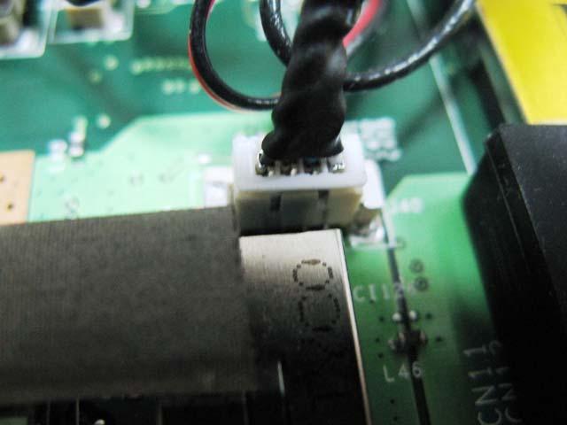

17 7-3:Pull out LCD LVDS Cable, Then Remove MICROPHONE Cable; 7-4:Pull out CMOS CABLE; 1 LCD LVDS Cable K H CMOS CABLE K H39 1


18 7-5:Take the Cable out of the slot in the direction shown below;


19 7-6:Remove 2pcs M2.5*5mm Screws in the direction shown below; Note:Screw driver torque is kgf.cm :Remove 4pcs M2.5*5mm Screws in the direction shown below; Note:Screw driver torque is kgf.cm Screw E H29 6


20 8 UP CASE ASSY 8-1:Remove 5pcs M2*3mm Screws, Then Remove Keyboard in the direction shown below; Note:Screw driver torque is 1.5~2.0kgf.cm :Remove Keyboard Cable in the direction shown below; 1 Screw E H Keyboard S1N-3UTC131-C54 1


21 8-3:Remove 2pcs M2*3mm Screws, Then Remove FFC CABLE(Launch Board ) in the direction shown below; Note:Screw driver torque is 1.5~1.8kgf.cm :Remove Launch Board in the direction shown below; 1 Screw E H Launch Board KA-01S 1 3 Launch Board FFC CABLE K1C J36 1
 in the")
")
22 8-5:Remove Touchpad FPC (connected with M/B ) in the direction shown below; 1 Touchpad FPC (To M/B ) K1C J36 1
23 8-6:Remove 15pcs M2.5*L5mm Screws in the direction shown below; Note:Screw driver torque is 2.0~2.5kgf.cm Screws E H29 15


24 8-7:Remove DUMMYCARD_EXPRESS,Then Remove CARD READ in the direction shown below; 1 DUMMYCARD_EXPRESS E2P H CARD READ E2P H76 1


25 8-8:Remove 3pcs M2*L3 mm Screws in the direction shown below; Note:Screw driver torque is1.8±0.2kgf.cm Screws E H29 3


26 8-9:Remove 2pcs M2.5*4 mm Screws, Then Remove SPEAKER ASSY in the direction shown below; Note:Screw driver torque is1.8±0.2kgf.cm Screws E H SPEAKER ASSY S F33 1
 in the direction shown below; Note:Screw driver torque")

27 8-10:Remove 3pcs M2*4mm Screws, Then RemoveTouchpad FPC (connected with Button ) in the direction shown below; Note:Screw driver torque is1.5~1.8kgf.cm : Remove Touchpad Bracket in the direction shown below; 1 Screws E43-I H Touchpad Bracket E2M Y28 1


28 8-12:Remove Touchpad FPC (To M/B ), Then Remove Touch Pad Board in the direction shown below; 1 Touchpad FPC (To M/B ) K1C J TouchPad Button Board KD-01S 1


29 8-13:Remove TOUCHPAD MODULE in the direction shown below; 1 TOUCHPAD MODULE S SD2 1
 8-15:Remove FFC Cable")
")
30 8-14:Remove FFC CABLE(Launch Board ) in the direction shown below; FFC CABLE(Launch 1 Board ) 8-15:Remove FFC Cable Touchpad FFC (To Button ); K1C J Touch Pad Board S SD2 1 2 Touchpad FFC (To Button ) K1C J36 1


31 8-16:Remove MICROPHONE in the direction as below; 1 MICROPHONE S N44 1


32 8-17:Remove 1pcs M2*3mm Screw,Then Remover BLUETOOTH ANTENN in the direction shown below; Note:Screw driver torque is1.8±0.2kgf.cm 1 1 Screws E H BLUETOOTH ANTENNA S H UPPER CASE ASSY C132-H74 1
 in the direction shown below; 1 USB Board Cable K1C-1026017-J36")
33 9 LOWER CASE ASSY PR601(MS-163K)Disassemble SOP 9-1:Remove (USB Board Cable) in the direction shown below; 1 USB Board Cable K1C J36 1


34 9-2:Remove USB Board in the direction shown below; Note:Screw driver torque is 1.5~2.0kgf.cm 1 USB Board KC-01S 1


35 9-3:Pull out Bluetooth Cable,Then Remove MICROPHONE Cable in the direction shown below; 1 BLUETOOTH CABLE K H MICROPHONE CABLE S N44 1


36 9-4:Remove 1pcs M 2.5*5 mm Screw, Then Remove M/B in the direction shown below;; Note:Screw driver torque is1.8±0.2kgf.cm 1 9-5:Remov Low Case ASSY in the direction shown below;


37 1 MAIN Board K1-01S 1 2 Low Case ASSY D26D-H Screws E H29 1
38 10 LCD MODULE ASSY 10-1:Remove 8pcs LCD Rubbers,Then Remove 8pcs M2.5*5mm screws in the direction shown below; Note:Screw driver torque is 1.5~2.0kgf.cm LCD BEZEL RUBBER E2Y Y Screw E H29 8

39 10-2:Disassemble LCD Bezel with the following instruction ; 1 LCD BEZEL E2P-634B211-Y31 1


40 10-3:Remove 4pcs M2.5*5mm screws, Then Remove 1pcs magnet in the direction shown below; Note:Screw driver torque is3.5+/-0.2kgf.cm :Remove LCD_HINGE_L-R in the direction shown below; 1 Screw E H MAGNET E2Y SF7 1 3 LCD_HINGE_L E2M G LCD_HINGE_R E2M G60 1


41 10-5:Remove Inverter Cable in the direction shown below; 10-6:Remove Inverter Module in the direction shown below; 1 Notebook Inverter S SG3 1


42 10-7:Remove DISPLAY MODULE in the direction shown below; 1 DISPLAY MODULE S1J-640G024-CC1 1


43 10-8:Remove CMOS Cable,Remove CMOS Camera Module in the direction shown below; 1 CMOS Camera Module S1F AF5 1 2 CMOS Cable K H39 1


44 10-9:Remove 4pcs M2.5*5mm screws, Then Remove ANTENNA in the direction shown below; Note:Screw driver torque is 1.5~1.8kgf.cm ANTENNA/HIGH-TEK/RIGHT S H ANTENNA/HIGH-TEK/LEFT S H Screw E H LCD COVER ASSY A212-H74 1

45 10-10:Remove LCD LVDS Cable in the direction shown below; 1 LCD LVDS Cable K H Display Module S1J-640G024-CC1 1


46 10-11:Remove 8pcs M2*3mm Screws as illustration, Then Remove LCD Bracket in the direction shown below; Note:Screw driver torque is 1.5~2.0kgf.cm Screw E H LCD-Bracket E2M Y28 2
47 PR601(MS-163K)screws specification Photo Screw specification Label (M2.5*L5MM) black (M2*3MM)white (M2*4MM) white (M2.5*4MM) black
48 PR601(MS-163K)screws specification 1 BOTTOM DOOR ASSY total 24Pcs screws, specification: Photo Screw specification label (M2.5*L5) black

49 PR601(MS-163K)screws specification 2 THERMAL-KIT and WIRELESS CARD total 7Pcs screws, specification: Photo Screw specification label (M2.5*L5) black (M2*L3)white Note:CPU Thermal Module screws on the order of lock

50 PR601(MS-163K)screws specification 3 UPCASE ASSY and SPEAKER ASSY total 10Pcs screws, specification: Photo Screw specification Label (M2.5*L5) black (M2*L3)white
51 PR601(MS-163K)screws specification 4 LCD BEZEL total 8Pcs screws, specification: Photo Screw specification label (M2.5*L5) black
52 PR601(MS-163K)screws specification 5 LCD MODULE ASSY total 16Pcs screws, specification: Photo Screw specification label (M2.5*L5) black (M2*L3)white

53 PR601(MS-163K)screws specification 6 UP CASE and LOWER CASES total 3pcs screws, specification: Photo Screw specification label (M2*L3)white
54 7 NB total 1pcs screw, specification: PR601(MS-163K)screws specification Photo Screw specification label (M2.5*L5) black

white")
55 PR601(MS-163K)screws specification 8 Touch Pad Board total 6pcs screws,specification: Photo Screw specification label (M2*L3)white (M2*4MM) white (M2.5*4MM) black
GT735(MS-1721)Disassemble SOP
Disassemble SOP") 1 Battery Pack 2 BOTTOM DOOR ASSY 3 THERMAL-KIT And CPU Module 4 RAM TUNER And WLAN Module 5 HDD Module ASSY 6 ODD Module ASSY 7 HINGE COVER ASSY 8 UPPER CASE ASSY 9 LOWER CASE ASSY 10 LCD MODULE ASSY
1 Battery Pack 2 BOTTOM DOOR ASSY 3 THERMAL-KIT And CPU Module 4 RAM TUNER And WLAN Module 5 HDD Module ASSY 6 ODD Module ASSY 7 HINGE COVER ASSY 8 UPPER CASE ASSY 9 LOWER CASE ASSY 10 LCD MODULE ASSY
GX720 (MS-1722)Disassemble SOP
Disassemble SOP") GX720 (MS-1722)Disassemble SOP 1 Battery Pack 2 BOTTOM DOOR ASSY 3 THERMAL-KIT And CPU Module 4 RAM WLAN And TUNER Module 5 HDD Module ASSY 6 ODD Module ASSY 7 HINGE COVER ASSY 8 UP CASE ASSY 9 LOWER CASE
GX720 (MS-1722)Disassemble SOP 1 Battery Pack 2 BOTTOM DOOR ASSY 3 THERMAL-KIT And CPU Module 4 RAM WLAN And TUNER Module 5 HDD Module ASSY 6 ODD Module ASSY 7 HINGE COVER ASSY 8 UP CASE ASSY 9 LOWER CASE
EX310 (MS-1333)Disassemble SOP
Disassemble SOP") EX310 (MS-1333)Disassemble SOP 1 Battery Pack 2 BOTTOM DOOR ASSY 3 WLAN THERMAL-KIT And CPU Module 4 MDC And RAM Module 5 HDD Module ASSY 6 ODD Module ASSY 7 HINGE COVER ASSY 8 UP CASE ASSY 9 LOWER CASE
EX310 (MS-1333)Disassemble SOP 1 Battery Pack 2 BOTTOM DOOR ASSY 3 WLAN THERMAL-KIT And CPU Module 4 MDC And RAM Module 5 HDD Module ASSY 6 ODD Module ASSY 7 HINGE COVER ASSY 8 UP CASE ASSY 9 LOWER CASE
GX620 (MS-1651)Disassemble SOP
Disassemble SOP") GX620 (MS-1651)Disassemble SOP 1 Battery Pack 2 BOTTOM DOOR ASSY 3 THERMAL-KIT And CPU Module 4 RAM WLAN And TUNER Module 5 HDD Module ASSY 6 ODD Module ASSY 7 HINGE COVER ASSY 8 UP CASE ASSY 9 LOWER CASE
GX620 (MS-1651)Disassemble SOP 1 Battery Pack 2 BOTTOM DOOR ASSY 3 THERMAL-KIT And CPU Module 4 RAM WLAN And TUNER Module 5 HDD Module ASSY 6 ODD Module ASSY 7 HINGE COVER ASSY 8 UP CASE ASSY 9 LOWER CASE
GX630 (MS-1652)Disassemble SOP
Disassemble SOP") GX630 (MS-1652)Disassemble SOP 1 Battery Pack 2 BOTTOM DOOR ASSY 3 THERMAL-KIT And CPU Module 4 RAM WLAN And TUNER Module 5 HDD Module ASSY 6 ODD Module ASSY 7 HINGE COVER ASSY 8 UP CASE ASSY 9 LOWER CASE
GX630 (MS-1652)Disassemble SOP 1 Battery Pack 2 BOTTOM DOOR ASSY 3 THERMAL-KIT And CPU Module 4 RAM WLAN And TUNER Module 5 HDD Module ASSY 6 ODD Module ASSY 7 HINGE COVER ASSY 8 UP CASE ASSY 9 LOWER CASE
CX420 (MS-1453) Disassemble Guide
 Disassemble Guide") CX420 (MS-1453) Disassemble Guide 1 BATTERY PACK 2 BOTTOM DOOR ASSY 3 HDD MODULE 4 ODD MODULE 5 THERMAL-KIT CPU DRAM 6 KEYBOARD 7 SEPARATE UPPER CASE AND LOWER CASE 8 LOWER CASE ASSY 9 UPPER CASE ASSY
CX420 (MS-1453) Disassemble Guide 1 BATTERY PACK 2 BOTTOM DOOR ASSY 3 HDD MODULE 4 ODD MODULE 5 THERMAL-KIT CPU DRAM 6 KEYBOARD 7 SEPARATE UPPER CASE AND LOWER CASE 8 LOWER CASE ASSY 9 UPPER CASE ASSY
U210 (MS-1241) Disassemble Guide
 Disassemble Guide") U210 (MS-1241) Disassemble Guide 1 KEYBOARD 2 BATTERY PACK 3 BOTTOM DOOR ASSY 4 HDD MODULE 5 LOWER CASE ASSY 6 SEPARATE UPPER CASE 7 THERMAL-KIT DRAM 8 UPPER CASE ASSY 9 LCD MODULE ASSY 1 KEYBOARD 1.1:Remove
U210 (MS-1241) Disassemble Guide 1 KEYBOARD 2 BATTERY PACK 3 BOTTOM DOOR ASSY 4 HDD MODULE 5 LOWER CASE ASSY 6 SEPARATE UPPER CASE 7 THERMAL-KIT DRAM 8 UPPER CASE ASSY 9 LCD MODULE ASSY 1 KEYBOARD 1.1:Remove
Assembly Procedure. Chapter
 Chapter 3 Assembly Procedure Please follow the information provided in this section to perform the complete assembly procedure of the Eee PC 1101HA. Be sure to use proper tools described before. A fter
Disassembly Procedure
 Chapter 2 Disassembly Procedure Please follow the information provided in this section to perform the complete disassembly procedure of the notebook. Be sure to use proper tools described before. SUS A7T
Disassembly Procedure
 Chapter 2 Disassembly Procedure Please follow the information provided in this section to perform the complete disassembly procedure of the Eee PC 1201HA. Be sure to use proper tools described before.
Disassembly Procedure
 Chapter 3 Disassembly Procedure Please follow the information provided in this section to perform the complete disassembly procedure of the notebook. Be sure to use proper tools described before. A SUS
GT735 (MS-1721) Part Name & Part Number. Key Parts MAIN BOARD / SUB PC BOARD MODEM S C59 MODEM S Q09 MAIN BOARD S
 Part Name & Part Number. Key Parts MAIN BOARD / SUB PC BOARD MODEM S C59 MODEM S Q09 MAIN BOARD S") GT735 (MS-1721) Key Parts Part Name & Part Number Description Remark MAIN BOARD / SUB PC BOARD MODEM S52-2801180-C59 CASTLENET/ML3054_201 MODEM S52-2801190-Q09 QCOM/MA560-7 01 MAIN BOARD 607-17211-01S
GT735 (MS-1721) Key Parts Part Name & Part Number Description Remark MAIN BOARD / SUB PC BOARD MODEM S52-2801180-C59 CASTLENET/ML3054_201 MODEM S52-2801190-Q09 QCOM/MA560-7 01 MAIN BOARD 607-17211-01S
Table of contents. VGN-FSxx series Disassemble Instruction. Section Title Page
 VGN-FSxx series Instruction Table of contents Section Title Page 1 Disassembly Procedures Outline Fixture for disassembly 2 Disassembly procedure flow chart 3 2 Disassembly components Disassembly battery
Disassembly Procedure
 Chapter 2 Disassembly Procedure Please follow the information provided in this section to perform the complete disassembly procedure of the notebook. Be sure to use proper tools described before. A SUS
Disassembly Procedure
 Chapter 2 Disassembly Procedure Please follow the information provided in this section to perform the complete disassembly procedure of the notebook. Be sure to use proper tools described before. A SUS
GE40/CR42 (MS-1492) Disassemble Guide
 Disassemble Guide") 1 BATTERY PACK 2 HDD&ODD MODULE/BOTTOM DOOR 3 THERMAL-KIT DRAM MODULE 4 CPU&WLAN MODULE 5 SEPARATE UPPER CASE AND LOWER CASE 6 LOWER CASE ASSY 7 LCD MODULE ASSY 1 BATTERY PACK 1.1:Move the Unlock button
1 BATTERY PACK 2 HDD&ODD MODULE/BOTTOM DOOR 3 THERMAL-KIT DRAM MODULE 4 CPU&WLAN MODULE 5 SEPARATE UPPER CASE AND LOWER CASE 6 LOWER CASE ASSY 7 LCD MODULE ASSY 1 BATTERY PACK 1.1:Move the Unlock button
Disassembly Procedure
 Chapter 3 Disassembly Procedure Please follow the information provided in this section to perform the complete disassembly procedure of the notebook. Be sure to use proper tools described before. A SUS
KN1Series Notebook consists of various modules. This chapter describes
 Chapter 2 Disassembly Procedure Please follow the information provided in this section to perform the complete disassembly procedure of the notebook. Be sure to use proper tools described before. KNSeries
ASUS A2000 Series Notebook consists of various modules. This chapter
 Chapter 2 Disassembly Procedure Please follow the information provided in this section to perform the complete disassembly procedure of the notebook. Be sure to use proper tools described before. ASUS
Upgrade & Replacement
 Chapter 4 Upgrade & Replacement Follow the individual procedures in this chapter to perform the notebook s upgrade and replacement of various major components. A sus A7V Series Notebook is an all-in-one
TravelMate 6493 Series Disassembly Instruction
 TravelMate 6493 Series Disassembly Instruction please refer to http://csd.acer.com.tw PRINTED IN TAIWAN Chapter 3 Machine Disassembly and Replacement This chapter contains step-by-step procedures on how
Assembly Procedure. Chapter
 PROCEDURE Chapter 1 Assembly Procedure Please follow the information provided in this section to perform the complete assembly procedure of the notebook. Be sure to use proper tools described before. After
WEASEL N/B MAINTENANCE
 2. System Assembly & Disassembly 2.1 System View 2.1.1 Front View ❶ Microphone Connector ❷ Audio Input Connector ❸ Audio Output Connector ❹ Top Cover Latch ❹ ❶ ❸ ❷ 2.1.2 Left-Side View ❶ VGA Port ❷ S-Video
Disassembly Manual T19
 Disassembly Manual T19 version change by date 0.1 Copied text from written notes DE 18-10-2005 0.2 Added photos & corrected layout DE 19-10-2005 Page 1 of 15 Battery & Dummy Cards 1. Remove the Battery.
Service Manual (LS40, LS50) LG Electronics
 LG Electronics") Service Manual (LS40, LS50) LG Electronics 00 Battery Pack. Push the battery latch in the direction shown below; then slide the battery pack out of the slot. 00 Hard Disk Drive Remove the battery pack
Service Manual (LS40, LS50) LG Electronics 00 Battery Pack. Push the battery latch in the direction shown below; then slide the battery pack out of the slot. 00 Hard Disk Drive Remove the battery pack
Disassembly Manual Version 1.1
 EasyNote K5 Disassembly Manual Version 1.1 Required Tools Disassembly Instructions DIP Switch Setting Reassembly Instructions Required Tools ll EasyNote K5 maintenance procedures can be performed using
Upgrade & Replacement
 Chapter 4 Upgrade & Replacement Follow the individual procedures in this chapter to perform the notebook s upgrade and replacement of various major components. Z84Jc Series Notebook is a 2 spindles product,
Disassembly Procedure
 Chapter 3 Disassembly Procedure Please follow the information provided in this section to perform the complete disassembly procedure of the notebook. Be sure to use proper tools described before. ASUS
Product End-of-Life Disassembly Instructions
 Product End-of-Life Disassembly Instructions Product Category: Notebooks and Tablet PCs Marketing Name / Model [List multiple models if applicable.] HP EliteBook 2570p Notebook PC Purpose: The document
ww.battery-adapter.com
 Removing and replacing an FRU Lenovo G470/G475/G570/G575 This section presents exploded figures with the instructions to indicate how to remove and replace the FRU. Make sure to observe the following general
Upgrade & Replacement
 Chapter 5 Upgrade & Replacement Follow the individual procedures in this chapter to perform the notebook s upgrade and replacement of various major components. A sus A6000U Series Notebook is a 2 spindles
Installation & Replacement
 Installation & Replacement Follow the individual procedures to perform the notebook s installation and replacement of various major components. Z70N Series Notebook is a fusion of flexibility, style and
Product End-of-Life Disassembly Instructions
 Product End-of-Life Disassembly Instructions Product Category: Notebooks and Tablet PCs Marketing Name / Model [List multiple models if applicable.] HP Classmate Notebook PC Purpose: The document is intended
Disassembly Instruction LIFEBOOK E733
 Disassembly Instruction LIFEBOOK E733 Contents Notes on installing and removing boards and components 2 Mandatory Support Bulletins 3 Removing the battery 4 Removing the ODD 5 Removing the memory modules
Packard Bell. EasyNote BU Series. Disassembly Guide
 Packard Bell EasyNote BU Series Disassembly Guide Table of Contents Overview...3 Technician Notes...3 Disassembly Instructions...3 Reassembly Instructions...3 Required Tools...3 Battery...4 Memory...4
Installation & Replacement
 Chapter 5 Installation & Replacement Follow the individual procedures to perform the notebook s installation and replacement of various major components. Series Notebook balances novelty and mobility in
Easy Note Alpha Disassembly. Required Tools Disassembly Instructions Reassembly Instructions
 Easy Note Alpha Disassembly Required Tools Disassembly Instructions Reassembly Instructions Required Tools All Easy Note Alpha maintenance procedures can be performed using the following tools: Tweezers
LifeBook P7120D Assembly
 LifeBook P7120D Assembly ESD Precautions are required when working on this LifeBook computer. 1. Connect the left microphone cable to the microphone PCB. 2. Insert them both into the rear cover of the
TravelMate 280 Exploded Diagram. www MK-Electronic de. Chapter 6 125
 TravelMate 280 Exploded Diagram Chapter 6 125 Cables LCD COAXIAL CABLE 15 XGA CABLE LCD COAXIAL 15 XGA 7 LAUNCH BOARD CABLE CABLE LAUNCH BOARD S50 INVERTER CABLE CABLE LED & INVERTER POWER CORD 125V 3PIN
Product End-of-Life Disassembly Instructions Product Category: Notebooks and Tablet PCs
 Product End-of-Life Disassembly Instructions Product Category: Notebooks and Tablet PCs Marketing Name / Model [List multiple models if applicable.] HP OMEN Notebook PC 15 Purpose: The document is intended
Packard Bell. EasyNote BG Series. Disassembly Guide
 Packard Bell EasyNote BG Series Disassembly Guide Table of Contents Overview...3 Technician Notes...3 Disassembly Instructions...3 Reassembly Instructions...3 Required Tools...3 Battery...4 Hard Disk...4
Figure 4-29 Removing the CPU compartment cover
 4 Replacement Procedures 4.9 CPU 4 4.9 CPU Removing the CPU To remove the CPU, follow the steps below. 1. Turn the computer upside down and remove two M2.5 4 security screws securing the CPU compartment
Sabio Digital SD-KN1 Notebook Assembly Guide
 Sabio Digital SD-KN1 Notebook Assembly Guide Rev. 1.4 Sabio Digital KN1 Assembly Guide 1 of 11 www.sabioproducts.com Table of Contents Section 1.0 - Overview... 3 Section 2.0 - Before You Begin... 3 Section
Installation & Replacement
 Chapter 5 Installation & Replacement Follow the individual procedures to perform the notebook s installation and replacement of various major components. Series Notebook balances novelty and mobility in
How to disassemble Toshiba Satellite T135, T135D, T130, T130D laptop base.
 How to disassemble Toshiba Satellite T135, T135D, T130, T130D laptop base. In this guide I show how to disassemble a Toshiba Satellite T135 laptop base. All laptop disassembly steps should be very similar
Product End-of-Life Disassembly Instructions
 Product End-of-Life Disassembly Instructions Product Category: Notebooks and Tablet PCs Marketing Name / Model [List multiple models if applicable.] HP Stream Notebook PC 13 HP Stream Notebook PC HP Stream
FIELD REPLACEABLE UNIT DOCUMENTATION. Satellite TM. A20 Series GENERAL INFORMATION. Tools Required for Proper Disassembly and Reassembly:
 GENERAL INFORMATION Tools Required for Proper Disassembly and Reassembly: 1. Phillips Screwdriver (Size 0&1) 2. 4mm Flat head Screwdriver 3. Case Separator 4. ESD Wrist Strap 5. ESD mats 6. Tweezers Before
Dell Inspiron Mini 10 RAM Replacement
 Upgrade or replace RAM to boost speed and performance. Written By: Danielle Jarecki ifixit CC BY-NC-SA www.ifixit.com Page 1 of 12 INTRODUCTION This guide will give step-by-step instructions on how to
4.1 General. 4 Replacement Procedures
 4.1 General This chapter explains how to disassemble the computer and replace Field Replaceable Units (FRUs). It may not be necessary to remove all the FRUs in order to replace one. The chart below is
Product End-of-Life Disassembly Instructions Product Category: Notebooks and Tablet PCs
 Product End-of-Life Disassembly Instructions Product Category: Notebooks and Tablet PCs Marketing Name / Model [List multiple models if applicable.] HP EliteBook 840 G2 Notebook PC Purpose: The document
Product End-of-Life Disassembly Instructions
 Product End-of-Life Disassembly Instructions Product Category: Notebooks and Tablet PCs Marketing Name / Model [List multiple models if applicable.] HP EliteBook Folio 9480m Purpose: The document is intended
FIELD REPLACEABLE UNIT DOCUMENTATION. Satellite Pro TM Series GENERAL INFORMATION. Tools Required for Proper Disassembly and Reassembly:
 GENERAL INFORMATION Tools Required for Proper Disassembly and Reassembly: 1. Phillips Screwdriver (Size 0&1) 2. Flat head Screwdriver 3. Security Torx (Size 7) 4. Case Separator 5. ESD Wrist Strap 6. ESD
X500 Parts Replacement Instructions
 X500 Parts Replacement Instructions This document is intended for service personnel. It provides information not found in the user manual. For information such as replacing the battery pack, hard disk
FIELD REPLACEABLE UNIT DOCUMENTATION
 Satellite TM 1700 Series GENERAL INFORMATION Tools Required for Proper Disassembly and Reassembly: 1. Phillips Screwdriver (Size 1) 2. Flat head screwdriver (5mm) 3. Hex driver (5mm) 4. Case Separator
Satellite Pro TM Series GENERAL INFORMATION. Disassembly and Reassembly:
 GENERAL INFORMATION Disassembly and Reassembly: 1. Phillips Screwdriver (Size 0&1) 2. Flat head Screwdriver 3. Case Separator 4. ESD Wrist Strap 5. ESD mats 6. Tweezers Before attempting any of the following
Installation Guide. Copyright 2005 MSI Computer Corp.
 Installation Guide Copyright 2005 MSI Computer Corp. Overview: 1013 is shipped out as a barebone. Some of the components are equipped while some are not. This installation guide provides you with the information
Le Disassembly. Required Tools Disassembly Instructions Reassembly Instructions
 Le Div@ Disassembly Required Tools Disassembly Instructions Reassembly Instructions Required Tools All Le Div@ maintenance procedures can be performed using the following tools: Tweezers Small flat-head
CHAPTER 6. FRU (Field-Replaceable Unit) list. Introduction Exploded diagram FRU list. www MK-Electronic de
 list. Introduction Exploded diagram FRU list. www MK-Electronic de") CHAPTER 6 FRU (Field-Replaceable Unit) list Introduction Exploded diagram FRU list 163 Introduction CHAPTER 6: FRU (Field-Replaceable Unit) list This chapter gives you the FRU (field-replaceable-unit)
CHAPTER 6 FRU (Field-Replaceable Unit) list Introduction Exploded diagram FRU list 163 Introduction CHAPTER 6: FRU (Field-Replaceable Unit) list This chapter gives you the FRU (field-replaceable-unit)
Product End-of-Life Disassembly Instructions
 Product End-of-Life Disassembly Instructions Product Category: Notebooks and Tablet PCs Marketing Name / Model [List multiple models if applicable.] HP Split 13 x 2 Notebook PC Purpose: The document is
Chapter 4 Replacement Procedures
 Chapter 4 Replacement Procedures 4 4-ii Satellite P30 Series Maintenance Manual Chapter 4 Contents 4.1 General... 4-1 4.2 Battery... 4-7 4.3 PC Card... 4-8 4.4 HDD... 4-10 4.5 Optical Drive Module... 4-12
Inspiron 22. Service Manual Series. Regulatory Model: W17B Regulatory Type: W17B001
 Inspiron 22 3000 Series Service Manual Regulatory Model: W17B Regulatory Type: W17B001 Notes, cautions, and warnings NOTE: A NOTE indicates important information that helps you make better use of your
Chapter 4 Replacement Procedures
 Chapter 4 Replacement Procedures 4 Replacement Procedures 4 4-ii Satellite R10 Maintenance Manual (960-509) 4 Replacement Procedures Chapter 4 Contents 4.1 Overview... 4-1 Safety Precautions... 4-2 Before
Product End-of-Life Disassembly Instructions Product Category: Notebooks and Tablet PCs
 Product End-of-Life Disassembly Instructions Product Category: Notebooks and Tablet PCs Marketing Name / Model [List multiple models if applicable.] Compaq Presario CQ61 Name / Model #2 Name / Model #3
Written By: John Sutton
 Replacing the fan on your HP g7-2275 dx. Written By: John Sutton ifixit CC BY-NC-SA www.ifixit.com Page 1 of 20 INTRODUCTION Laptop cooking your lap? This guide will walk you through replacing your fan.
Presario 1200 Series Models: XL101-XL113, XL115, XL118-XL127. This section explains the removal and replacement procedures for the 1200XL unit.
 Removal Sequence Presario 1200 Series This section explains the removal and replacement procedures for the 1200XL unit. Serial Number Location Report the unit s serial number 1 to Compaq when requesting
Product End-of-Life Disassembly Instructions Product Category: Notebooks and Tablet PCs
 Product End-of-Life Disassembly Instructions Product Category: Notebooks and Tablet PCs Marketing Name / Model [List multiple models if applicable.] HP ProBook 6440b Notebook PC Name / Model #2 Name /
C202SA: Disassembly Guide
 ASUS Computer International C202SA: Disassembly Guide PN: 90NX00Y2-M00040 PN: 90NX00Y2-M00050 IMPORTANT NOTICE: This document is intended for ASUS Authorized Service Providers only. Performing any repairs
Product End-of-Life Disassembly Instructions Product Category: Notebooks and Tablet PCs
 Product End-of-Life Disassembly Instructions Product Category: Notebooks and Tablet PCs Marketing Name / Model [List multiple models if applicable.] HP EliteBook 755 G5 Notebook PC Purpose: The document
Toshiba Satellite A210 Motherboard
 Toshiba Satellite A210 Motherboard Replacement In this guide you will learn how to properly remove the Motherboard. Written By: Devin ifixit CC BY-NC-SA www.ifixit.com Page 1 of 12 INTRODUCTION Before
FIELD REPLACEABLE UNIT DOCUMENTATION. Portege R100 GENERAL INFORMATION. Tools Required for Proper Disassembly and Reassembly:
 Portege TM GENERAL INFORMATION Tools Required for Proper Disassembly and Reassembly: 1. Phillips Screwdriver (Size 0) 2. Flat head Screwdriver 3. Case Separator 4. ESD Wrist Strap 5. ESD mat 6. Tweezers
Dell Inspiron XPS and Inspiron 9100 Service Manual
 Dell Inspiron XPS and Inspiron 9100 Service Manual Dell Inspiron XPS and Inspiron 9100 Service Manual Before You Begin Memory Module, Mini PCI Card, and Devices System Components Subwoofer Bluetooth Card
Product End-of-Life Disassembly Instructions Product Category: Personal Computers
 Product End-of-Life Disassembly Instructions Product Category: Personal Computers Marketing Name / Model [List multiple models if applicable.] HP 260 G1 DM Business PC Purpose: The document is intended
Dell TM XFR D630. Fully Rugged Notebook. Service Manual
 Dell TM XFR D630 Fully Rugged Notebook Service Manual Notes, Notices, and Cautions NOTE: A NOTE indicates important information that helps you make better use of your computer. NOTICE: A NOTICE indicates
Exploded Diagram THE SYSTEM. www MK-Electronic de. 90 Chapter 6
 Exploded Diagram THE SYSTEM 90 Chapter 6 LOGIC UPPER TravelMate 270 Chapter 6 91 LCD 14.1 TravelMate270 92 Chapter 6 LCD 15 TravelMate 270 Chapter 6 93 DVD TravelMate 270 NOTE: The exploded diagrams for
Toshiba Satellite A210 Fan Replacement
 Toshiba Satellite A210 Fan Replacement In the guide you will learn how to remove the fan from the Toshiba Satellite A210. Written By: Youlen ifixit CC BY-NC-SA www.ifixit.com Page 1 of 9 INTRODUCTION Before
Product End-of-Life Disassembly Instructions Product Category: Notebooks and Tablet PCs
 Product End-of-Life Disassembly Instructions Product Category: Notebooks and Tablet PCs Marketing Name / Model [List multiple models if applicable.] OMEN X by HP Laptop PC 17 Purpose: The document is intended
Product End-of-Life Disassembly Instructions
 Product End-of-Life Disassembly Instructions Product Category: Notebooks and Tablet PCs Marketing Name / Model [List multiple models if applicable.] HP ZBook 15 G3 Mobile Workstation Purpose: The document
Product End-of-Life Disassembly Instructions
 Product End-of-Life Disassembly Instructions Product Category: Notebooks and Tablet PCs Marketing Name / Model [List multiple models if applicable.] HP Stream Laptop PC 14 Purpose: The document is intended
Dell XPS 14z Owner s Manual
 Dell XPS 14z Owner s Manual Computer model: L412z Regulatory model: P24G series Regulatory type: P24G001 Notes, Cautions, and Warnings NOTE: A NOTE indicates important information that helps you make better
Product End-of-Life Disassembly Instructions
 Product End-of-Life Disassembly Instructions Product Category: Notebooks and Tablet PCs Marketing Name / Model [List multiple models if applicable.] HP 15 Notebook PC Purpose: The document is intended
Dell Precision M4600 Owner's Manual
 Dell Precision M4600 Owner's Manual Regulatory Model P13F Regulatory Type P13F001 Notes, Cautions, and Warnings NOTE: A NOTE indicates important information that helps you make better use of your computer.
Dell Latitude E6500 Teardown
 Dell Latitude E6500 Teardown Disassembling the Dell Latitude E6500. Step by Step. I disassemble it down to the base assembly. Written By: Luis Gomez ifixit CC BY-NC-SA www.ifixit.com Page 1 of 16 INTRODUCTION
Motion F5m C5m Parts Reference Guide
 Motion F5m C5m Parts Reference Guide Copyright 2003-206 Xplore Technologies Corp. All rights reserved. No part of this publication may be copied, reproduced, or translated, without the prior written consent
Dell Inspiron System Board
 Dell Inspiron 17-5749 System Board Replacement This guide will instruct users on the procedure of removing/replacing the Dell Inspiron 17-5749 system board. Written By: Christopher Tran ifixit CC BY-NC-SA
PowerBook G4 Aluminum 12" GHz Display Data Cable Replacement
 PowerBook G4 Aluminum 12" 1-1.5 GHz Display Data Cable Replacement Written By: Matthew Newsom ifixit CC BY-NC-SA www.ifixit.com Page 1 of 47 INTRODUCTION Replace a damaged display data cable to restore
PowerBook G4 Aluminum 12" GHz Left Clutch Hinge Replacement
 PowerBook G4 Aluminum 12" 1-1.5 GHz Left Clutch Hinge Replacement Written By: Matthew Newsom ifixit CC BY-NC-SA www.ifixit.com Page 1 of 50 INTRODUCTION Replace a broken clutch hinge to make your display
4.1 General 4 Replacement Procedures
 4.1 General 4 Replacement Procedures 4 1 4.1 General This chapter explains how to disassemble the computer and replace Field Replaceable Units (FRUs). Some replacement procedures may not require you to
Toshiba Satellite A105-S4011 Touchpad
 Toshiba Satellite A105-S4011 Touchpad Replacement This guide will instruct you on how to remove the current touchpad from this laptop and how to reinstall another. This is a straightforward process and
Product End-of-Life Disassembly Instructions
 Product End-of-Life Disassembly Instructions Product Category: Personal Computers Marketing Name / Model [List multiple models if applicable.] HP Compaq 8200 Elite USDT Business PC Name / Model #2 Name
MacBook Core 2 Duo Clutch Cover
 MacBook Core 2 Duo Clutch Cover Replacement Replace the clutch cover on your MacBook Core 2 Duo. Written By: Ben Eisenman ifixit CC BY-NC-SA www.ifixit.com Page 1 of 29 INTRODUCTION Replace the curved
Product End-of-Life Disassembly Instructions
 Product End-of-Life Disassembly Instructions Product Category: Notebooks and Tablet PCs Marketing Name / Model [List multiple models if applicable.] HP EliteBook 725 G2 Notebook PC Purpose: The document
MacBook Pro 15" Core Duo Model A1150 ExpressCard Cage Replacement
 MacBook Pro 15" Core Duo Model A1150 ExpressCard Cage Replacement Written By: irobot ifixit CC BY-NC-SA www.ifixit.com Page 1 of 17 INTRODUCTION You can again use ExpressCard accessories by replacing a
Product End-of-Life Disassembly Instructions
 Product End-of-Life Disassembly Instructions Product Category: Notebooks and Tablet PCs Marketing Name / Model [List multiple models if applicable.] HP x2 210 G2 Detachable PC Purpose: The document is
Dell Latitude 5420/E5420/E5420m Owner's Manual
 Dell Latitude 5420/E5420/E5420m Owner's Manual Regulatory Model P15F Regulatory Type P15F001 Notes, Cautions, and Warnings NOTE: A NOTE indicates important information that helps you make better use of
HP Compaq 6730b Display Replacement
 Here is a HP Compaq 6730b with a cracked LCD after having been dropped. This is a straight forward repair. Written By: oldturkey03 ifixit CC BY-NC-SA www.ifixit.com Page 1 of 11 INTRODUCTION This laptop
www MK-Electronic de FRU (Field Replaceable Unit) List Chapter 6
 List Chapter 6") Chapter 6 FRU (Field Replaceable Unit) List This chapter gives you the FRU (Field Replaceable Unit) listing in global configurations of TravelMate C210 series products. Refer to this chapter whenever ordering
Chapter 6 FRU (Field Replaceable Unit) List This chapter gives you the FRU (Field Replaceable Unit) listing in global configurations of TravelMate C210 series products. Refer to this chapter whenever ordering
PowerBook G3 Pismo I/O EMI Shield Replacement
 PowerBook G3 Pismo I/O EMI Shield Replacement Written By: irobot ifixit CC BY-NC-SA www.ifixit.com Page 1 of 23 INTRODUCTION A thin metal shield resides above the ports that protects from electromagnetic
ASUS P527 Service Manual (L1&L2)
") ASUS P527 Service Manual (L1&L2) 1 1 EQUIPMENT NEED... 3 2 INTRODUCTION... 4 2.1 ABOUT THIS SERVICE MANUAL... 4 2.2 OVERVIEW... 4 2.3 PRODUCT SPECIFICATION... 5 3 DISASSEMBLY / ASSEMBLY PROCEDURE... 6
ASUS P527 Service Manual (L1&L2) 1 1 EQUIPMENT NEED... 3 2 INTRODUCTION... 4 2.1 ABOUT THIS SERVICE MANUAL... 4 2.2 OVERVIEW... 4 2.3 PRODUCT SPECIFICATION... 5 3 DISASSEMBLY / ASSEMBLY PROCEDURE... 6
Product End-of-Life Disassembly Instructions
 Product End-of-Life Disassembly Instructions Product Category: Notebooks and Tablet PCs Marketing Name / Model [List multiple models if applicable.] HP Elite x2 1012 G1 Tablet Purpose: The document is
Product End-of-Life Disassembly Instructions Product Category: Personal Computers
 Product End-of-Life Disassembly Instructions Product Category: Personal Computers Marketing Name / Model [List multiple models if applicable.] HP ProOne 440 G4 All-in-One Business PC Purpose: The document