MOD-RFID125 User Manual. All boards produced by Olimex are ROHS compliant. Rev.A, February 2008 Copyright(c) 2008, OLIMEX Ltd, All rights reserved
|
|
|
- Adrian Burns
- 5 years ago
- Views:
Transcription

1 MOD-RFID125 User Manual All boards produced by Olimex are ROHS compliant Rev.A, February 2008 Copyright(c) 2008, OLIMEX Ltd, All rights reserved
2 INTRODUCTION: FEATURES: MOD-RFID125 is an RFID station, able to read Manchester-encoded 64-bit EM4102 tags with 64 periods of carrier frequency per data bit. All the complexity of RFID tag detection, verification and decoding are handled by MOD-RFID125. After it strips the header and the checksums user is given the 40-bit ID of the transponder tag. MOD-RFID125 supports three distinctive modes of operation, easily switched by a single button press. It can emulate USB HID keyboard and input the read TAG ID directly to any Windows application, including the venerable Notepad. Or it can emulate USB CDC serial port for easy access from custom user applications using standard code for COM port access. The third option allows access from any standard 5V UART, allowing easy integration with existing microcontroller applications. - Supports Manchester-encoded 64-bit EM4102 RFID tags with 64 periods of carrier frequency per data bit; - Base RFID frequency 125kHz; - USB port connection to PC; - Standard 5V UART 9600,8N1 connection to user microcontroller boards; - Three modes of operation, easily changed by pressing the button; - USB HID keyboard emulation mode; - USB CDC serial port emulation mode; - UART connection mode; - Simple command-line interface in USB CDC and UART modes for configuration and data acquisition; - Two LEDs indicating device status and tag presence; - Support for continuous and periodic RF scanning to better suit user power requirements; - Ships with default mode USB HID and default configuration: continuous read, scan always, one report per second, LEDs activated; ELECTROSTATIC WARNING: REQUIREMENTS: The MOD-RFID125 board is shipped in protective anti-static packaging. The board must not be subject to high electrostatic potentials. General practice for working with static sensitive devices should be applied when working with this board. Cables: 1.8 meter USB A-B cable. Power: External 6-9V DC power supply (applicable only for MOD-RFID125- BOX in UART mode). Software: Software needed for USB HID keyboard mode: - Notepad or other text editor. Software needed for USB CDC and UART modes:
3 - HyperTerminal or other terminal program.
: UEXT pin Abbrev.")

4 SUPPORTED RFID TAGS: MOD-RFID125 supports RFID transponder tags with the following characteristics: - Based on EM4102 chip; - 125kHZ carrier frequency; - 64-bit ROM, continuously transmitted; - 64 periods of carrier frequency per data bit; - Manchester encoding; UEXT CONNECTOR SCHEMATICS (only for MOD-RFID125-BOX): UEXT pin Abbrev. description 1 NC Not Connected 2 GND Ground 3 RXD UART Receive Data (MOD-RFID125 input) 4 TXD UART Transmit Data (MOD-RFID125 output) 5 NC Not Connected 6 NC Not Connected 7 NC Not Connected 8 NC Not Connected 9 NC Not Connected 10 NC Not Connected POWER SUPPLY: Normally the device is supplied from USB. MOD-RFID125-BOX can be connected to external 6-9V DC power supply. This can relief the USB hub power supply when device is in USB HID or USB CDC mode. External power supply is mandatory for UART mode of operation. POWER SUPPLY CABLE CONNECTION Pin Connect to V DC 2 GND

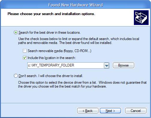
5 LEDS: In normal mode the GREEN LED is on whenever the RF antenna circuit is active and scanning for RFID tags. The RED LED switches on whenever a valid RF TAG ID is being scanned and decoded successfully. The LEDs can be switched off to save power consumption. See the Command Line Interface section for more information. In boot loader mode the LEDs have other meaning. See the Firmware Upgrade section for more information. PC DRIVER INSTALLATION: Drivers for the USB HID mode are integrated in Windows XP/Vista. The driver for USB CDC mode is available from our website. Windows installation steps are the following: 1. Download and unzip the file MOD-RFID125-drivers.zip in a temporary directory. 2. Plug the programmer in the USB port. 3. Point the Device Wizard to the temporary directory. 4. Windows will complain that drivers are not signed. Click Continue. 5. Click finish. Screen shots of the steps are shown below:


6
7 Linux distributions normally include drivers both for USB HID and USB CDC classes. Depending on which driver is loaded in the kernel, user should look either for /dev/ttyacmn or /dev/ttyusbn where "n" is a number, assigned by the kernel to the plugged device. USB HID MODE: USB CDC MODE: When device is connected via USB to a host PC it will represent itself as USB HID keyboard. When an RFID transponder is detected in the vicinity, the module will type the HEX-representation of the transponder ID. To use the device in this mode: 1. Open Notepad. 2. Plug in the device in the USB port of the PC. 3. Put an RFID tag in front of the device. The TAG ID will be entered in the currently opened text file. There is no need for OS driver because all major operating systems include USB HID drivers. NOTE: This mode does not allow configuration of device parameters. MOD- RFID125 is shipped with default configuration for continuous read and one second repeat. If this must be changed then device must be switched to USB CDC mode and configured using the serial command line interface. In this mode the device represents itself as USB CDC virtual serial port. It provides a simple shell-like command line interface for configuring and interacting with the module. The device echoes back the typed characters and waits for Carriage Return (Enter) before processing the line input. See Command Line Interface for more information on the supported commands. Any terminal software can be used to open the COM port, assigned by the OS, and type in commands.
8 UART MODE: In this mode there is no need for USB connection. Instead the device must be connected via UEXT connector to a TTL-level UART of a microcontroller system of choice. It expects the peer to be configured with 9600 bps, 8bit character, no parity, 1 stop bit. The communication is otherwise the same as in USB CDC mode, but there is no need for USB. Again, all entered characters are echoed back. SWITCHING OPERATING MODES: The current mode of operation can be selected by pressing and holding the button of the device. After two seconds the LEDs will start to blink and will show the code for the next selected mode. When button is released, the device will reboot and enter the selected mode. Selected mode is remembered between power downs. The assigned codes are: LED Status Description Red Green Previous State State After Button Is Released blinks off UART USB HID off blinks USB HID USB CDC blinks blinks USB CDC UART COMMAND LINE INTERFACE (USB CDC and UART modes): The command line interface, available in USB CDC and UART modes, allows device configuration and reading of successfully decoded TAG IDs. Just open the serial port assigned to MOD-RFID125 using HyperTerminal or similar terminal program, and start typing commands. For the impatient: type '?' and press enter to see a short help for the supported commands. Any typed character will be echoed back; 'enter' will force the module to process the input command line. 1. Command? This command prints a short help message, describing the available commands and their arguments. 2. Command i This command prints a short information about firmware version, hardware board revision, and currently selected configuration. 3. Command b This command forces the device to enter boot loader mode. After executing this command the device will disconnect itself from USB, switch to boot loader mode, and reconnect itself in anticipation of receiving a firmware upgrade image. See the section Firmware Upgrade for more information.
9 4. Command r This command is only valid if device is in single read mode (see below). It will trigger a single TAG read. If TAG ID is successfully read, it will be printed. Otherwise if operation timed out, zeros will be printed. 5. Command msxx Set single read mode. The XX parameter must be a decimal value, indicating the TAG read timeout in seconds. Example setting single read mode with 15 seconds timeout: ms15 6. Command mcfr Set continuous read mode with frequency F (Hz) and repeat report interval R (seconds). Both F and R must be single digit decimal numbers. If F is 0 then RF antenna is constantly switched on and the device is scans continuously for tags. Otherwise if F is 1-5, the device will switch the antenna on F times per second. If R is 0 then a successfully read RF tag ID is reported only once. Otherwise if R is 1-9, the device will report the tag ID every R seconds until the tag is seen in the proximity. Example continuous scanning, single report per seen tag: mc00 Example scan once per second, single report per seen tag: mc10 Example scan twice per second, report a seen tag every second: mc21 Example continuous scanning, report a seen tag every 5 seconds: mc05 7. Command mle Set LED mode. If E is 0, LEDs will be disabled. Otherwise if E is 1, LEDs will be enabled. Example enabling LEDs: ml1 Example disabling LEDs to conserve power: ml0 Below is a screen shot of command line session using HyperTerminal:
. 2. Press and hold the button. 3.")
10 FIRMWARE UPGRADE: MOD-RFID125 contains a built-in boot loader for easy firmware upgrade. Device enters boot loader mode if the application FLASH section is corrupted. To force the device to enter boot loader mode for manual firmware update do the following: 1. Disconnect the device from any power source (external DC, USB). 2. Press and hold the button. 3. Power up the device by connecting it to USB. 4. Device now must be in boot loader mode, indicated by the LED light sequence: a. RED on, GREEN off. b. RED off, GREEN on. c. RED off, GREEN off. Button can now be released. The device will stay in boot loader mode until it is power cycled. Boot loader implements the standard protocol XMODEM with CRC16 for firmware update. User is free to use his favorite terminal client (HyperTerminal, minicom, etc) to upload the firmware images taken from our website. Boot loader uses an USB virtual serial port that is baudrate agnostic. As an alternative we provide a simple Windows GUI application for users who don t want to or cannot use terminal software. After the firmware image is uploaded the target will blink the GREEN LED if update was successful, otherwise it will blink the RED LED if firmware image was invalid or update was unsuccessful. Device stays in this state until it is power cycled. WARNING: Upgrade from UEXT via UART is NOT supported! Boot loader supports only USB.
11 ELECTRICAL CHARACTERISTICS: Symbol Description Condition Min Typ Max Uni ts V CC Power Supply Voltage V I CC,NOLE Power Supply Current Idle (RF scanning not active) 20 ma D with deactivated LEDs. Continuous scanning 120 ma I CC Power Supply Current with activated LEDs. Scanning 2 times per second 36 ma Continuous scanning 130 ma Scanning 2 times per second 40 ma
12 ORDER CODE: MOD-RFID125 assembled and tested (no kit, no soldering required) MOD-RFID125-BOX assembled and tested (no kit, no soldering required) How to order? You can order to us directly or by any of our distributors. Check our web for more info. Revision history: REV.A - create April 2008
13 Disclaimer: 2008 Olimex Ltd. All rights reserved. Olimex, logo and combinations thereof, are registered trademarks of Olimex Ltd. Other terms and product names may be trademarks of others. The information in this document is provided in connection with Olimex products. No license, express or implied or otherwise, to any intellectual property right is granted by this document or in connection with the sale of Olimex products. Neither the whole nor any part of the information contained in or the product described in this document may be adapted or reproduced in any material from except with the prior written permission of the copyright holder. The product described in this document is subject to continuous development and improvements. All particulars of the product and its use contained in this document are given by OLIMEX in good faith. However all warranties implied or expressed including but not limited to implied warranties of merchantability or fitness for purpose are excluded. This document is intended only to assist the reader in the use of the product. OLIMEX Ltd. shall not be liable for any loss or damage arising from the use of any information in this document or any error or omission in such information or any incorrect use of the product.
MOD-RFID125-BOX User Manual
 MOD-RFID125-BOX User Manual All boards produced by Olimex are ROHS compliant Rev.B, May 2011 Copyright(c) 2011, OLIMEX Ltd, All rights reserved Page 1 INTRODUCTION: FEATURES: MOD-RFID125-BOX is an RFID
MOD-RFID125-BOX user's manual
 MOD-RFID125-BOX user's manual All boards produced by Olimex are ROHS compliant Rev.C, February 2013 Copyright(c) 2011, OLIMEX Ltd, All rights reserved Page 1 DISCLAIMER 2013 Olimex Ltd. Olimex, logo and
MOD-RFID1356 User Manual. All boards produced by Olimex are ROHS compliant. Rev.A, May 2008 Copyright(c) 2008, OLIMEX Ltd, All rights reserved
 2008, OLIMEX Ltd, All rights reserved") MOD-RFID1356 User Manual All boards produced by Olimex are ROHS compliant Rev.A, May 2008 Copyright(c) 2008, OLIMEX Ltd, All rights reserved INTRODUCTION: FEATURES: MOD-RFID1356 is an RFID station, able
MOD-RFID1356 User Manual All boards produced by Olimex are ROHS compliant Rev.A, May 2008 Copyright(c) 2008, OLIMEX Ltd, All rights reserved INTRODUCTION: FEATURES: MOD-RFID1356 is an RFID station, able
MOD-RFID1356 user's manual. All boards produced by Olimex are ROHS compliant. Rev. C, June 2015 Copyright(c) 2008, OLIMEX Ltd, All rights reserved
 2008, OLIMEX Ltd, All rights reserved") MOD-RFID1356 user's manual All boards produced by Olimex are ROHS compliant Rev. C, June 2015 Copyright(c) 2008, OLIMEX Ltd, All rights reserved DISCLAIMER 2015 Olimex Ltd. Olimex, logo and combinations
MOD-RFID1356 user's manual All boards produced by Olimex are ROHS compliant Rev. C, June 2015 Copyright(c) 2008, OLIMEX Ltd, All rights reserved DISCLAIMER 2015 Olimex Ltd. Olimex, logo and combinations
AVR-P20 development board Users Manual
 AVR-P20 development board Users Manual All boards produced by Olimex are ROHS compliant Revision A, October 2005 Copyright(c) 2009, OLIMEX Ltd, All rights reserved Page 1 INTRODUCTION: The AVR Microcontrollers
AVR-P development board Users Manual
 AVR-P40-8515 development board Users Manual All boards produced by Olimex are ROHS compliant Revision A, January 2002 Copyright(c) 2009, OLIMEX Ltd, All rights reserved Page 1 INTRODUCTION: The AVR Microcontroller
PIC-32MX development board Users Manual
 PIC-32MX development board Users Manual All boards produced by Olimex are ROHS compliant Rev.A, June 2008 Copyright(c) 2008, OLIMEX Ltd, All rights reserved INTRODUCTION: The NEW PIC-32MX board uses the
PIC-P28-USB development board Users Manual
 PIC-P28-USB development board Users Manual Rev.A, June 2007 Copyright(c) 2007, OLIMEX Ltd, All rights reserved INTRODUCTION: PIC-P28-USB board was designed in mind to create board which to allow easy interface
MOD-BT development board Users Manual
 MOD-BT development board Users Manual All boards produced by Olimex are ROHS compliant Rev. B, September 2009 Copyright(c) 2010, OLIMEX Ltd, All rights reserved Page 1 INTRODUCTION BOARD FEATURES MOD-BT
MOD-MRF24J40 development board Users Manual
 MOD-MRF24J40 development board Users Manual All boards produced by Olimex are ROHS compliant Rev. Initial, May 2011 Copyright(c) 2011, OLIMEX Ltd, All rights reserved Page 1 INTRODUCTION: MOD-MRF24J40
AVR- M16 development board Users Manual
 AVR- M16 development board Users Manual All boards produced by Olimex are ROHS compliant Rev. C, January 2005 Copyright(c) 2009, OLIMEX Ltd, All rights reserved Page1 INTRODUCTION AVR-M16 is header board
MSP430-PG2231 development board Users Manual
 MSP430-PG3 development board Users Manual All boards produced by Olimex are ROHS compliant Revision A, June 0 Copyright(c) 0, OLIMEX Ltd, All rights reserved Page INTRODUCTION: MSP430-PG3 is prototype
HOW TO USE ESP8266 WITH ARDUINO IDE
 HOW TO USE ESP8266 WITH ARDUINO IDE This document applies for the following products: ESP8266-EVB; ESP8266-EVB-BAT; ESP8266-EVB-BAT-BOX Document revision B, February 2017 All boards produced by Olimex
PIC-P40 development board Users Manual
 PIC-P40 development board Users Manual All boards produced by Olimex are ROHS compliant Rev.E, February 008 Copyright(c) 008, OLIMEX Ltd, All rights reserved Page INTRODUCTION: PIC-P40 board is development
HOW TO UPGRADE ESP8266 BOARDS USING ESP FLASH DOWNLOAD TOOLS
 HOW TO UPGRADE ESP8266 BOARDS USING ESP FLASH DOWNLOAD TOOLS This document applies for the following products: ESP8266-EVB; ESP8266-EVB-BAT; ESP8266-EVB-BAT-BOX; MOD-ESP8266-WIFI-DEV; MOD-ESP8266-WIFI;
MSP-RFLINK development board Users Manual
 MSP-RFLINK development board Users Manual All boards produced by Olimex are ROHS compliant Revision Initial, May 0 Copyright(c) 0, OLIMEX Ltd, All rights reserved Page INTRODUCTION: MSP-RFLINK is wireless.4
CHANGING THE MODES OF MOD-WIFI-ESP8266-DEV
 CHANGING THE MODES OF MOD-WIFI-ESP8266-DEV REFERENCE Revision B, March 2018 Designed by OLIMEX Ltd, 2014 All boards produced by Olimex LTD are ROHS compliant DISCLAIMER 2018 Olimex Ltd. Olimex, logo and
CAN4VSCP - RS232. Smart CAN4VSCP serial interface. Reversion
 CAN4VSCP - RS232 Smart CAN4VSCP serial interface Reversion 1.0-2014-02-28 Abstract CAN4VSCP-RS22 is a very simple interface module for connecting a computers RS-232 interface to the VSCP CAN bus. The module
LPC-P1114 development board Users Manual
 LPC-P1114 development board Users Manual All boards produced by Olimex are ROHS compliant Revision A, May 2010 Copyright(c) 2009, OLIMEX Ltd, All rights reserved Page 1 INTRODUCTION LPC-P1114 is development
LPC-H1343 development board Users Manual
 LPC-H343 development board Users Manual All boards produced by Olimex are ROHS compliant Revision B, June 0 Copyright(c) 0, OLIMEX Ltd, All rights reserved Page INTRODUCTION LPC-H343 is header board with
S125 Multi-Purpose 125 KHz RFID Reader USER MANUAL. 9V/24V DC Operating Voltage, AC (optional) KHz RFID EM4100/2 Cards & Tags
 KHz RFID EM4100/2 Cards & Tags") S125 Multi-Purpose 125 KHz RFID Reader 44 mm USER MANUAL MULTI PURPOSE 84 mm ONLINE & OFFLINE MODE BUILT-IN RELAY 125 KHz RFID EM4100/2 Cards & Tags 9V/24V DC Operating Voltage, AC (optional) 3 Online
S125 Multi-Purpose 125 KHz RFID Reader 44 mm USER MANUAL MULTI PURPOSE 84 mm ONLINE & OFFLINE MODE BUILT-IN RELAY 125 KHz RFID EM4100/2 Cards & Tags 9V/24V DC Operating Voltage, AC (optional) 3 Online
PIC-LCD-3310 development board Users Manual
 PIC-LCD-3310 development board Users Manual Rev.A, July 2008 Copyright(c) 2008, OLIMEX Ltd, All rights reserved INTRODUCTION: PIC-LCD-3310 is development board with PIC18F67J50, NOKIA 3310 BW 84x48 pixels
MICRO-1356 MULTI-PROTOCOL READER
 MICRO-1356 MULTI-PROTOCOL READER The Micro-1356 reader is a miniature multi-protocol RFID reader suited for embedded applications, such as handheld readers or door key card readers. The Micro-1356 has
Revision: 0.30 June Intel Server Board S1200RP UEFI Development Kit Firmware Installation Guide
 Revision: 0.30 June 2016 Intel Server Board S1200RP UEFI Development Kit Firmware Installation Guide Intel Server Board S1200RP UEFI Development Kit Firmware Installation Guide INFORMATION IN THIS DOCUMENT
Olimex PIC-KIT3 In-circuit programmer/debugger
 Olimex PIC-KIT3 In-circuit programmer/debugger USER S MANUAL Revision B, October 2013 All boards produced by Olimex LTD are ROHS compliant DISCLAIMER 2013 Olimex Ltd. Olimex, logo and combinations thereof,
MOD-BT and Duinomite boards errata
 MOD-BT and Duinomite boards errata Connection fix Revision A, September 2012 All boards produced by Olimex LTD are ROHS compliant A13-OLinuXino User's Manual DISCLAIMER 2012 Olimex Ltd. Olimex, logo and
PIC-IO development board User's Manual
 PIC-IO development board User's Manual Rev.C, October 0 Copyright(c) 0, OLIMEX Ltd, All rights reserved All boards produced by Olimex are ROHS compliant INTRODUCTION: PIC-IO board was designed as simple
MICRO-1356 MULTI-PROTOCOL READER
 MICRO-1356 MULTI-PROTOCOL READER Unique Features: The datasheet for the Micro-1356- USB and Micro-1356 readers are the same. The Micro-1356-USB reader is a USB version of the Micro-1356 embedded RFID reader
BlueEva+S42M Evaluation Kit User Guide. 1VV Rev
 BlueEva+S42M Evaluation Kit User Guide 1VV0301390 Rev. 1 2018-01-15 SPECIFICATIONS ARE SUBJECT TO CHANGE WITHOUT NOTICE NOTICE While reasonable efforts have been made to assure the accuracy of this document,
DVI Desktop 4-Port Audio-Combo-KVM Switch
 DVI Desktop 4-Port Audio-Combo-KVM Switch User s Manual (DS-12800) Index 1 INTRODUCTION... 2 1.1 FEATURES... 2 1.2 PHYSICAL DIAGRAM... 3 1.3 PACKAGE CONTENTS... 3 2 SPECIFICATIONS... 4 2.1 GENERAL... 4
Dual H-Bridge shield. Dual H-Bridge shield - board user manual. Shield for DC motor control with IFX9202. About this document.
 - board user manual Dual H-Bridge shield About this document Scope and purpose This document details the functionality and the required steps for running the Dual H-Bridge shield. Included are instructions
AVR-TLCD-128CAN development board Users Manual
 AVR-TLCD-128CAN development board Users Manual Rev.A, July 2008 Copyright(c) 2008, OLIMEX Ltd, All rights reserved INTRODUCTION: AVR-TLCD-128CAN adds cool LCD and touchscreen interface to your next project.
DATASHEET 4D SYSTEMS TURNING TECHNOLOGY INTO ART. microusb Programming Adaptor. USB to UART Serial Bridge
 TURNING TECHNOLOGY INTO ART DATASHEET microusb Programming Adaptor µusb-pa5 USB to UART Serial Bridge Document Date: 27 th November 2013 Document Revision: 1.1 Uncontrolled Copy when printed or downloaded.
DATASHEET 4D SYSTEMS. uusb-pa5 uusb-pa5-ii. microusb Programming Adaptor TURNING TECHNOLOGY INTO ART. USB to UART Serial Bridge
 DATASHEET TURNING TECHNOLOGY INTO ART microusb Programming Adaptor -II USB to UART Serial Bridge Document Date: 17 th July 2015 Document Revision: 2.0 Uncontrolled Copy when printed or downloaded. Please
UPDATING THE FIRMWARE IN FRAME BASED MODULES...
 7700/7800 MultiFrame Manual TABLE OF CONTENTS 1. OVERVIEW... 1 1.1. REQUIREMENTS... 1 1.1.1. Requirements Serial Port Upgrade Method... 1 1.1.2. Requirements FTP Upgrade Method (For VistaLINK Capable Modules
Revision: 0.30 June Intel Server Board S2600CP4 UEFI Development Kit Firmware Installation Guide
 Revision: 0.30 June 2013 Intel Server Board S2600CP4 UEFI 2.3.1 Development Kit Intel Server Board S2600CP4 UEFI 2.3.1 Development Kit INFORMATION IN THIS DOCUMENT IS PROVIDED IN CONNECTION WITH INTEL
GammaTron USB Module
 GammaTron USB Module Product ID. : 710 Board Rev. : 1.00 Date : June 24, 2007 Firmware Rev. : 1.11 Beta Innovations (c) 2006 http://www.betainnovations.com Table of Contents Main Features...5 Introduction...6
PIC-P67J60 development board Users Manual
 PIC-P67J60 development board Users Manual Rev.A, July 2008 Copyright(c) 2008, OLIMEX Ltd, All rights reserved INTRODUCTION: If you want to build your own Internet enabled device this is the board for you.
First Steps. esom/sk5 esom/3517 Embedded Linux Starter Kit
 esom/sk5 esom/3517 Embedded Linux Starter Kit First Steps SSV Embedded Systems Dünenweg 5 D-30419 Hannover Phone: +49 (0)511/40 000-0 Fax: +49 (0)511/40 000-40 E-mail: sales@ssv-embedded.de Document Revision:
DATASHEET 4D SYSTEMS TURNING TECHNOLOGY INTO ART. USB to Serial UART Bridge Converter. Document Date: 5 th September 2012 Document Revision: 1.
 TURNING TECHNOLOGY INTO ART DATASHEET USB to Serial UART Bridge Converter µusb-mb5 Document Date: 5 th September 2012 Document Revision: 1.0 Uncontrolled Copy when printed or downloaded. Please refer to
BLE232: Manual Copyright 2014 taskit GmbH
 BLE232 Manual BLE232: Manual Copyright 2014 taskit GmbH BLE232 All rights to this documentation and to the product(s) described herein are reserved by taskit GmbH. This document was written with care,
2/4-PORT AUDIO KVM SWITCH
 2/4-PORT AUDIO KVM SWITCH User Manual DS-12423 / DS-12443 Index 1 INTRODUCTION... 3 1.1 FEATURES... 3 1.2 PHYSICAL DIAGRAM... 4 1.3 PACKAGE CONTENTS... 4 2 SPECIFICATIONS... 5 2.1 GENERAL... 5 2.2 LED
ATtiny104 Xplained Nano. Preface. AVR 8-bit Microcontrollers USER GUIDE
 AVR 8-bit Microcontrollers ATtiny104 Xplained Nano USER GUIDE Preface The Atmel ATtiny104 Xplained Nano evaluation kit is a hardware platform to evaluate the ATtiny104 microcontroller. Supported by the
USB-to-I2C Basic. Hardware User s Manual.
 USB-to-I2C Basic Hardware User s Manual http://www.i2ctools.com/ Information provided in this document is solely for use with the USB-to-I2C product from SB Solutions, Inc. SB Solutions, Inc. reserves
TD1205 / 1205P. TD1205 /1205P EVK Rev 1.1 User s Guide EVALUATION KIT USER S GUIDE FOR TDnext TD1205 / 1205P MODULE
 EVALUATION KIT USER S GUIDE FOR TDnext TD1205 / 1205P MODULE July 2016 - Rev 1.1 rfmodules.td-next.com Page 1 Disclaimer: The information in this document is provided in connection with Telecom Design
MOD-IO development board Users Manual
 MOD-IO development board Users Manual All boards produced by Olimex are ROHS compliant Rev. B, September 0 Copyright(c) 0, OLIMEX Ltd, All rights reserved Page INTRODUCTION MOD-IO is a small but powerful
User Guide. Date Apr BlueEva+C11/G2. Stollmann. E + V GmbH. User Guide
 Version r02 Date Apr 2009 Author: ta Date saved: 06.04.09 Ref: BlueEva+C11G2_User_Guide_r02.doc Revision: r02 Page 1 of 22 Note This device was developed for the purpose of communication in an office environment.
Chipset Evaluation and Development Loadboard Version 2
 IA MSC-UGLB2 Chipset Evaluation and Development Loadboard Version 2 User Guide Revision 1.0r IA MSC-UGLB2 rev 1.0r 0907 2007, Silicon Laboratories, Inc. Silicon Labs, Inc. 400 West Cesar Chavez Austin,
F2MC MB90385 series Evaluation Board Documentation. Revision Date Comment V New document
 F2MC MB90385 series Evaluation Board Documentation Revision Date Comment V1.0 08.25.02 New document 1 Warranty and Disclaimer To the maximum extent permitted by applicable law, Fujitsu Microelectronics
Serial Port Plug - F2M01SXA Brief Datasheet. Features. Applications. General Description. Provides transparent RS-232 serial cable replacement.
 Serial Port Plug - F2M01SXA Features Provides transparent RS-232 serial cable replacement. No need for external drivers. Power is supplied via the D-SUB or mini-usb connector. Supports the Bluetooth Serial
SMiRF v1 Serial Miniature RF Link 8/25/2004
 interface and protocol requirements for the SMiRF USB Powered Wireless link. Please report typos, inaccuracies, and especially unclear explanations to us at spark@sparkfun.com. Suggestions for improvements
Evaluation Board for ELM4 / LSM4. Technical Reference Manual
 SWISS PRECISION V 1.4 01.11.2016 To prevent damage by electrostatic discharge (ESD), hold this Evaluation-Board at the edges only. You must be properly grounded before handling this sensitive product.
MOD-RS485-ISO. Isolated extension board with RS485 interface. USER S MANUAL Revision B, October 2012 Designed by OLIMEX Ltd, 2012
 MOD-RS485-ISO Isolated extension board with RS485 interface USER S MANUAL Revision B, October 2012 Designed by OLIMEX Ltd, 2012 All boards produced by Olimex LTD are ROHS compliant DISCLAIMER 2012 Olimex
FT232 Serial to USB Converter
 FT232 Serial to USB Converter Campus Component Pvt. Ltd. DISCLAIMER Information furnished is believed to be accurate and reliable at the time of publication. However, Campus Component Pvt. Ltd. assumes
UIO-HMI Digital I/Os & DAQ Board User Manual
 UIO-HMI-24 39 Digital I/Os & DAQ Board User Manual /2 2 UIO-HMI-24 Digital Inputs/Outputs & DAQ board with 39 channels and USB/Bluetooth/RF connectivity. Welcome to the world of Computer Automation. This
Communication of passive RFID Reader and. FOX3-2G/3G/4G series via RS-232 serial link. and its use to identify RFID tags in
 THIS DOCUMENT IS AVAILABLE AT HTTP://WWW.FALCOM.DE/ Communication of passive RFID Reader and FOX3-2G/3G/4G series via RS-232 serial link and its use to identify RFID tags in transportation and access management
Manual. Technical Specifications: Version 1.0.0, May Copyright Terabee 2016
 Copyright 2016 Manual Version 1.0.0, May 2016 Technical Specifications: Mounting: Size: Weight: Supply voltage: Supply current: Possible interfaces: Range: Update range: Range resolution: Accuracy: Field
LPC-P1114 development board Users Manual
 LPC-P4 development board Users Manual All boards produced by Olimex are ROHS compliant Revision B, November 0 Copyright(c) 0, OLIMEX Ltd, All rights reserved Page INTRODUCTION LPC-P4 is development board
WIZ140SR/WIZ145SR Datasheet
 WIZ140SR/WIZ145SR Datasheet ( Version 0.9 ) 2010 WIZnet Co., Ltd. All Rights Reserved. For more information, visit our website at http://www.wiznet.co.kr WIZ140SR/WIZ145SR Datasheet (WIZnet Co., Ltd.)
LPC-P1227 development board USER S MANUAL Initial release, March 2012 Designed by OLIMEX Ltd, 2011
 LPC-P1227 development board USER S MANUAL Initial release, March 2012 Designed by OLIMEX Ltd, 2011 All boards produced by Olimex LTD are ROHS compliant Disclaimer: 2012 Olimex Ltd. Olimex, logo and combinations
USER GUIDE EDBG. Description
 USER GUIDE EDBG Description The Atmel Embedded Debugger (EDBG) is an onboard debugger for integration into development kits with Atmel MCUs. In addition to programming and debugging support through Atmel
bdiaccess Installation Manual MPC85xx/P10xx/P20xx JTAG interface library by Abatron AG Manual Version 1.01 for BDI3000
 bdiaccess JTAG interface library MPC85xx/P10xx/P20xx Installation Manual Manual Version 1.01 for BDI3000 1992-2009 by Abatron AG bdiaccess for BDI3000 (MPC85xx/P10xx/P20xx) Installation Manual 2 1 Introduction...
Industrial RFID Reader
 Industrial RFID Reader User s Manual for the following models: FCC ID: IOL-125-AV1015 (6 Coil System) FCC ID: IOL-125-AV1016 (12 Coil System) FCC ID: IOL-125-AV1017 (24 Coil System) The device complies
LPC2148 DEV BOARD. User Manual.
 LPC2148 DEV BOARD User Manual www.coineltech.com www.coineltech.com Designed by CoiNel Technology Solutions LLP No-816, 2 nd Floor, 4 th B Cross, 9 th A Main, RPC Layout, Vijaynagar, Bangalore-560040 State:
Strike the keyboard for you when it sniffing the tag!
 Strike the keyboard for you when it sniffing the tag! No Programming Required! No Software Required! Just Plug and Play! Applications: 1) Employee identification 2) Time and attendance 3) Form filter to
BlueEva+S50/Central Evaluation Kit User Guide. 1VV Rev
 BlueEva+S50/Central Evaluation Kit User Guide 1VV0301519 Rev. 0 2018-03-16 SPECIFICATIONS ARE SUBJECT TO CHANGE WITHOUT NOTICE NOTICE While reasonable efforts have been made to assure the accuracy of this
EDBG. Description. Programmers and Debuggers USER GUIDE
 Programmers and Debuggers EDBG USER GUIDE Description The Atmel Embedded Debugger (EDBG) is an onboard debugger for integration into development kits with Atmel MCUs. In addition to programming and debugging
DVK kHz RFID Development Kit User Manual
 Features and Benefits Standard ISO communications User interface software RS232 serial communication Dedicated instruction set 6 to 9Volts supply compliant Ordering Information Part No. DVK90109 General
Getting Started. Proxmark III V2 User Guid. Overview. Feature.
 Proxmark III V2 User Guid Getting Started Overview The Proxmark III is an open-source device developed by Jonathan Westhues that enables sniffing, reading and cloning of RFID (Radio Frequency Identification)
GW-USB-05. User's Guide. FW v1.07. IQRF USB Gateway MICRORISC s.r.o. User_Guide_GW-USB-05_ Page 1
 FW v1.07 IQRF USB Gateway User's Guide 2016 MICRORISC s.r.o. www.iqrf.org User_Guide 160405 Page 1 Description is an IQRF gateway with USB connectivity. It is intended as an interface between IQRF network
How to upgrade firmware of Pi-931-X34CC and Pi-931-XA5 reader module
 S i l i c o n C r a f t How to upgrade firmware of Pi-931-X34CC and Pi-931-XA5 reader module Revision History Revision Date Description Change/Updated/Comment 1.0 February 2011 1 st Release 2.0 July 2012
Table 1. RS232 Serial Adapter DEBUG Connector Pin Descriptions
 RS232 SERIAL ADAPTER (EC2) USER S GUIDE 1. Contents The RS232 Serial Adapter (EC2) package contains the following items: RS232 Serial Adapter (RS232 to Debug Interface) 7 Ribbon Cable 2. RS232 Serial Adapter
First Steps. esom/sk4 esom/3517 Embedded Linux Starter Kit
 esom/sk4 esom/3517 Embedded Linux Starter Kit First Steps SSV Embedded Systems Dünenweg 5 D-30419 Hannover Phone: +49 (0)511/40 000-0 Fax: +49 (0)511/40 000-40 E-mail: sales@ssv-embedded.de Document Revision:
RS232 Relay Board-R242. User Manual. Jan 2012 Doc-R242-UM-Rev1.0 iknowvations.in
 User Manual 1/12 4 channel RS232 Relay Board with 9 Digitlal/Analog I/O Rs232 Data Acquisition Card Welcome to the world of Computer Automation. This RS232 Relay Board - R242 is a perfect companion for
The USB Debug Adapter package contains the following items: USB Debug Adapter (USB to Debug Interface) with attached 7 Ribbon Cable
 with attached 7 Ribbon Cable") USB DEBUG ADAPTER USER S GUIDE 1. Contents The USB Debug Adapter package contains the following items: USB Debug Adapter (USB to Debug Interface) with attached 7 Ribbon Cable 2. USB Debug Adapter Specifications
USB DEBUG ADAPTER USER S GUIDE 1. Contents The USB Debug Adapter package contains the following items: USB Debug Adapter (USB to Debug Interface) with attached 7 Ribbon Cable 2. USB Debug Adapter Specifications
SIM28M/28ML GPS Receiver Modem
 CAMPUS COMPONENT Pvt. Ltd. 1 DISCLAIMER Information furnished is believed to be accurate and reliable at the time of publication. However, Campus Component Pvt. Ltd. assumes no responsibility arising from
MP3 Trigger v2 User Guide
 Overview The MP3 Trigger v2 is a versatile, low-cost, low-power embedded audio unit that plays MP3 tracks directly from a FAT16-formatted microsd flash card to a stereo line-level 1/8 output jack, supporting
Bluetooth RS232 Serial Adapter
 Bluetooth RS232 Serial Adapter LM058 Table of contents 1. Introduction Page 1 2. Features Page 1 3. Packaging Page 2 4. General Specification Page 2 5. RS232 Interface Page 3 5.1 Pin Out Page 3 5.2 Signals
ROTOR CONTROL DXA. de K4JRG. User s Manual
 de K4JRG User s Manual , K4JRG User s Manual V1.05, Rev F4 JR Engineering, Corp 3521 SW 140 th Ave Miami, FL 33175 Phone 786.270.1610, x210 Fax 786.270.1609 email: k4jrg@k4jrg.org Table of Contents Welcome!...
GW-USB-06. User s Guide. IQRF USB Gateway. FW v MICRORISC s.r.o. User_Guide_GW-USB-06_ Page 1
 FW v1.04 IQRF USB Gateway User s Guide 2016 MICRORISC s.r.o. www.iqrf.org User_Guide_GW-USB-06_160122 Page 1 Description GW-USB-06 is an IQRF gateway with USB connectivity. It is intended as an interface
F²MC-8L FAMILY MB89201 SERIES FLASH PROGRAMMING 8-BIT MICROCONTROLLER APPLICATION NOTE. Fujitsu Microelectronics Europe Application Note
 Fujitsu Microelectronics Europe Application Note MCU-AN-300001-E-V10 F²MC-8L FAMILY 8-BIT MICROCONTROLLER MB89201 SERIES FLASH PROGRAMMING APPLICATION NOTE Revision History Revision History Date 2005-02-09
Universal RFID Socket board with USB interface
 Data Sheet UNI_USB.pdf 9 Pages Last Revised 18/03/13 Universal RFID Socket board with USB interface The Universal RFID Socket board is the baseboard for the MicroRWD RFID reader modules from IB Technology.
ADSP-218x Family EZ-ICE Hardware Installation Guide
 ADSP-218x Family EZ-ICE Hardware Installation Guide 2000 Analog Devices, Inc. ADSP-218x Family EZ-ICE Hardware Installation Guide a Notice Analog Devices, Inc. reserves the right to make changes to or
SM125 System SM125-IC 125 KHz RFID Chip SM125-M1 125 KHz RFID Module SM125-EK Evaluation Kit SMRFID 3.0 Software USER MANUAL
 SM125 System SM125-IC 125 KHz RFID Chip SM125-M1 125 KHz RFID Module SM125-EK Evaluation Kit SMRFID 3.0 Software USER MANUAL 2 1. INTRODUCTION 4 1.1 125 KHz RFID Systems 5 1.2 Evaluation Board Layout View
MOD-ZIGBEE-PIR sensor development board USER S MANUAL All boards produced by Olimex LTD are ROHS compliant
 sensor development board USER S MANUAL All boards produced by Olimex LTD are ROHS compliant Revision B, Januray 2013 Designed by OLIMEX Ltd, 2011 Disclaimer: 2012 Olimex Ltd. Olimex, logo and combinations
HMC1022 Digital Compass
 Key Features Based on Honeywell s HMC1022 solid-state magnetic sensor Choice of 2 Interface Options (UART/I2C) Standard Pin Headers come soldered Plug and Play Module SPECIFICATIONs Angular Measuring Range
CSB4-U USB driver installation
 12/05/2009 CSB4-U USB driver installation Headquarters, Europa SpringCard 13 voie la Cardon Parc Gutenberg 91120 Palaiseau FRANCE Phone : +33 (0) 164 53 20 10 Fax : +33 (0) 164 53 20 18 Americas SpringCard
How a 2d barcode scan engine to be integrated with your. I. The imager engine itself with TTL serial interface :
 How a 2d barcode scan engine to be integrated with your Kiosk, POS terminal or others system? By RTscan, June 2014 We have been often asked by our customers about how to integrate the 2d barc ode scan
Figure 1. JTAGAVRU1 application The JTAGAVRU1 is supported by AVR Studio. Updated versions of AVR Studio is found on
 JTAG AVR Emulator through USB Main Features AVR Studio Compatible Supports AVR Devices with JTAG Interface Emulates Digital and Analog On-Chip Functions Data and Program Memory Breakpoints Supports Assembler
EHB Serial Bluetooth
 Bluetooth to UART TTL 3.3V & 5V Abandoning the boring communication wire is a dream for most elec fans, this model is designed for this purpose. Using it, you can easy establish a wireless UART/RS232 communication
Bluetooth RS-232 Dongle. User s Manual BTS-100
 Bluetooth RS-232 Dongle User s Manual BTS-100 Table of Contents 1. INTRODUCTION... 2 2. PHYSICAL DIAGRAM... 3 3. BLUETOOTH PAIRING AND CONNECTING... 4 4. RS-232 INSTALLATION... 10 5. HYPERTERMINAL SETTING
Boot Loader for the Z51F6412 MCU
 Boot Loader for the Z51F6412 MCU AN037701-0215 Abstract This application note discusses how to create a boot loader program for the Z51F6412 microcontroller, a member of Zilog s Z8051 Family of Microcontrollers.
Neo_M660 GPRS Module Demo Board User Guide Version 1.0
 Neo_M660 GPRS Module Demo Board User Guide Version 1.0 Revision Record Issue Changes Date V1.0 Initial draft 2014-05 Copyright Neoway Technology Co., Ltd i Contents 1 Overview... 1 2 Interfaces... 1 3
BlueEva+SR Evaluation Kit User Guide. 1VV Rev
 BlueEva+SR Evaluation Kit User Guide 1VV0301280 Rev. 5 2018-03-01 SPECIFICATIONS ARE SUBJECT TO CHANGE WITHOUT NOTICE NOTICE While reasonable efforts have been made to assure the accuracy of this document,
User Manual. August 2008 Revision 1.0. SKH300 ibutton Reader Configuration Utility
 User Manual August 2008 Revision 1.0 SKH300 ibutton Reader Configuration Utility Copyright 2008 Jan. All Rights Reserved Manual Version 1.0 The information contained in this document is subject to change
JMY505G User's Manual
 JMY505G User's Manual (Revision 3.42) Jinmuyu Electronics Co. LTD 2011/6/28 Please read this manual carefully before using. If any problem, please mail to: jinmuyu@vip.sina.com Contents 1 Product introduction...
USER GUIDE. Atmel Segment LCD1 Xplained Pro. Preface
 USER GUIDE Atmel Segment LCD1 Xplained Pro Preface Atmel Segment LCD1 Xplained Pro is an extension board to the Atmel Xplained Pro evaluation platform. Segment LCD1 Xplained Pro is designed to kick-start
Firmware/Bootloader Update Manual
 UEL6000 Ethernet Firmware/Bootloader Update Manual General Remarks The only purpose of this manual is a description of the product. It must not be interpreted as a declaration of conformity for this product
ED40. Development Kit. Quick Start Guide
 ED40 Development Kit Quick Start Guide Disclaimer Honeywell International Inc. ( HII ) reserves the right to make changes in specifications and other information contained in this document without prior
GB-Ware. Quick Guide. Powered by: Tel: Fax Web:
 Powered by: GB-OS 6.1 GB-Ware Quick Guide GBWAQG201208-01 Global Technology Associates 3505 Lake Lynda Drive Suite 109 Orlando, FL 32817 Tel: +1.407.380.0220 Fax. +1.407.380.6080 Email: info@gta.com Web: