Dataman-S6 - User's Manual. Dataman-S6 Compact USB Programmer User's Manual
|
|
|
- Nathaniel Patterson
- 5 years ago
- Views:
Transcription

1 Dataman-S6 Compact USB Programmer User's Manual
2 Contents Chapter 1 Product Description 1-1 Introduction 1-2 Safety Information 1-3 Precautions 1-4 Operating System, Hardware Requirements 1-5 Accessories Chapter 2 Product Installation 2-1 Hardware Installation 2-2 Software Installation 2-3 Driver Installation Chapter 3 IC Insertion 3-1 General IC Insertion (DIP package) 3-2 Special IC Insertion via Adapter (Special package) Chapter 4 Software Operation 4-1 Main Screen IC Information Column Message Window Programming Result Statistics Other Operation Buttons 4-2 Device Select/Project Device Select Device Type Device Search Device Search Operators Device Search Results Selected Device History 4-3 File Load Load File Path File Format Source Select Destination Select Fill Unused With Function 4-4 Edit Display Mode (8 Bits/16 Bits) View/Edit Mode 4-5 Option Settings General System Settings Insertion Detection Device ID Check
3 4-5-4 Confirm Error List Programming Area Selection Message Column Settings Self-Test Function Device Options 4-6 Save Save File Path and Name Save File Format Buffer Range for Saving 4-7 Device Processing Procedure Read Data Confirm Erase Blank Check Program Verify Protect RUN ALL Description of Actions Chapter 5 Basic Operation Examples 5-1 Programming an MCU from user data located on the computer and protecting the IC 5-2 Reading the internal memory of an IC and saving the data out in Binary format 5-3 Using the system's Self Test function to detect and test the programmers hardware Chapter 6 Troubleshooting Chapter 7 Glossary of Terms
4 Chapter 1 Product Description 1-1 Introduction With 30 years experience Dataman is the world s leading provider of device programmers. We offer a comprehensive range of programming solutions suitable for every requirement from design and development to large scale production. We are committed to providing continued development, manufacturing and support and to deliver customer specific innovative solutions. All Dataman products come with comprehensive warranties, free lifetime support and free software updates via our website and telephone helpdesk. 1-2 Safety Information All the operations, maintenance and repair services are required to follow the below safety information. We do not take responsibility for unexpected problems by misusing the equipment. 1. The programmer must be connected to the host computer using the supplied Y type USB cable. Check that both USB plugs are connected to the computer and confirm that the available USB power is sufficient to operate the programmer correctly. If the computer is connected through a USB Hub it will need to be a powered hub (+5V/1A or above). 2. Do not operate the product near flammable gases. High-temperatures and humidity should also be avoided. 3. Do not remove the product's case to adjust or replace any internal parts. 4. Sockets or adapters are considered consumables. The life time is determined from the frequency of use specified in the manufactures specification. If a socket is used beyond the rated number of actuations specified by the manufacturer, the socket will start to give errors caused by poor contact. This will result in an increasing number of contact errors and burn failures. 5. When using this product as mass production or production for master tape, please take the appropriate testing precautions before assembling the completed product. All the risks attributed to using the product or operating the software are undertaken by the user. 6. This manual is for reference and preservation of the consumer. Product specifications and manuals are subject to change without notice. 7. The company or trademarks mentioned in this manual are the property of their respective owners. 1-3 Precautions 1. When you work with your IC using our programmer it will access the device using a high frequency signal. To ensure proper programming and high yield rates you must observe the following: a) During any operation with the IC (read / verify / programming / erase / blank check... etc) do not touch the IC or ZIF socket. When inserting an IC into the ZIF socket, please take note of basic electrostatic protection measures. 1
5 b) If you need adapters for other kinds of IC package (for example, TSOP, PLCC, TQFP, QFN... etc.) we would advise that you contact Dataman. Do not use inferior quality adapters or try to create adapters yourself. The Dataman-S6 programmer communicates with the IC using a high-frequency signal. If external adapters are of poor quality we will be unable to give any guarantee on the programming results! 2. When connecting the Dataman-S6 programmer to the computer please note: a) You must use the supplied Y-type USB cable. Check that both USB plugs are connected to the host computer before connecting the programmer. An ordinary single USB cable is not suitable as it will not supply enough power to the unit and you may experience problems with stability during programming. b) When the Dataman-S6 software is launched and connection to the programmer is established the programmer will check the USB power supply, if the power supply is not sufficient a warning message will be displayed. If you are using an external USB hub its supply may be limited. In which case you would need to use a power adapter capable of (5V, 1A or greater) to improve it. On the warning message window you can press the "Retry" button to re-test the supply once you have made a change. You can also press the "Cancel" button to skip the power detection. However by doing so the system can not guarantee 100% correct operation. 1-4 Operating System, Hardware Requirements Operating System: Windows XP / Windows Vista / Windows 7 CPU: PC / Pentium IV or above Memory: 512 MB RAM or above Hard disk space: 500 MB or more (main program) 1 GB or more (program buffer (depending on selected device capacity)) Monitor Resolution: 800 x 600 pixels or above Interface: USB 2.0 High Speed 2
6 Power Requirements: 2 x USB Ports providing +5 V power supply Dimensions: 130 (L) x 90 (depth) x 20 (high) mm Note: Height does not include ZIF Socket Weight: 290g Operating temperature: +5 to Accessories Programmer: 1 Special Y-USB cable: 1 CD-ROM (software and manual): 1 3
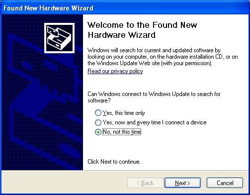
7 Chapter 2 Product Installation 2-1 Hardware Installation 1. Use the supplied Y-type USB cable connected two USB ports on the host computer. If you use an external USB Hub, please connect it to a power adapter rated at (5V,> 1A or above), and remove any other USB powered devices such as external hard drives...and so on. 2. The blue LED on the Dataman-S6 will not illuminate until the software driver has been installed. After installing the driver the programmers' LED will flash twice then turn off. When in operation the LED will be illuminated, when the software is closed down the LED will turn off. 2-2 Software Installation 1. Please note that when installing the software on your computer, the operating system will require "administrator" permissions. If you do not have administrator permissions it may result in an unsuccessful installation. 2. Insert the CD, the installation screen should automatically appear. If there's no installation screen please install through "My Computer" > CD-ROM drive > and execute the AUTORUN.EXE 3. Press the "Install" button to start the installation, modify the installation path and name of the start menu link if required. Finally press the "Finish" button to complete the software installation. 4. Next, click on the database installation files on the CD (or download from This will update the IC database. 2-3 Driver Installation 1. Please install the main software on your computer first and then connect the programmer to computer using the supplied Y-type USB cable. The driver installation will automatically start. 2. The first time the programmer is connected to the host PC it will display a message about finding new hardware, and will then ask if you want to go ahead and install the driver. Please follow these steps to complete the installation. 4

8 Check this item 5


9 3. The path is set to "C:\Dataman Programmers\USBDrv" (Check the item Include this location in the search.) check this item check this item Set the driver path Choose to continue the installation 4. After installation, you will see the the "Dataman-S6 device listed under Device manager Control Panel \ System \ Hardware \ Device Manager. This shows that the installation was successful. 6
![Press [Finish] To](/docs-images/86/94008295/images/10-0.jpg "Complete the")

10 Press [Finish] To Complete the installation This icon represents successful driver installation 7

11 Chapter 3 IC Insertion 3-1 General IC Insertion (DIP package) If the IC is in a DIP package it must be inserted into the programmers ZIF socket towards the bottom, with the index mark towards the top. Pin 1 of the IC should be at the upper left position as shown here. 3-2 Special IC Insertion via Adapter Socket (Special package) When the IC is not in a DIP package you must use a suitable package adapter. If the number of pins on the DIL header underneath the adapter is less than 48 then the adapter should be placed into the ZIF socket towards the bottom as with standard DIP devices above. The adapters are usually marked with a "1" to indicate the position of pin 1 on the device. Place the IC into the adapter socket matching the position of pin 1. 8
12 Chapter 4 Software Operation 4-1 Main Screen Shown below is the default interface you will see when starting the software. If you are starting the program for the first time no device will be selected and the software will automatically show the "Select Device" screen. The function key IC Information Message Column Saving Clear all messages The results of a single programming Programming Results Statistics Zeroing IC Information Column Displays the device's brand, serial number and packaging information. Programming data source, notes, check sum value and other information is also included Message Window Records all actions and results performed on the system. It will show the date and time in front of each line. The buttons on upper right corner of this window allow you to save or delete the data shown in this column Programming Result Statistics 9
![A running total of the statistic results from programming (only [RUN ALL] are recorded here). The right hand button- [>> 0] allows you to clear the results.](/docs-images/86/94008295/images/13-0.jpg "4-1-4 Other Operation Buttons 4-2 Device Select/Project 4-2-1 Device Select Allows the selection of an IC by full or partial part name.")
13 A running total of the statistic results from programming (only [RUN ALL] are recorded here). The right hand button- [>> 0] allows you to clear the results Other Operation Buttons 4-2 Device Select/Project Device Select Allows the selection of an IC by full or partial part name. Manufacturer LOGO Search Selected Device Manufacturer Part Number (package) IC Information Device Type IC type (ALL / EEPROM / FLASH / MPU/MCU...). Helps users select the appropriate IC by narrowing down the type of device technology that is shown in the search results Device Search Enter a full or partial IC part name to search the database for a match. You can use the "Space" key to separate search terms. The order of the search terms does not affect the results. The search operation is decided by operators. 10

14 4-2-4 Device Search Operators When multiple search terms are entered into this field the search result is performed in accordance with ALL search terms (AND), OR some of the terms (OR) Device Search Results Shows the IC part names matching the search terms and will change the search results based on type of device and part name Selected Device History The system will automatically record the last 20 selected devices. You can directly select any device from this list. The brand names and logos shown in our software remain the property of the respective companies. 11
 that will be loaded into the buffer. 4-3-2 File Format Select the format of the programming date file. If you are unsure about the format we recommend using the \"Auto Detect\" function.")
15 4-3 File Load Browse Search Records Automatically adjust to the selected IC's capacity Fill value for unused regions Load File Path The path to your programming data file (HEX, Binary...) that will be loaded into the buffer File Format Select the format of the programming date file. If you are unsure about the format we recommend using the "Auto Detect" function Source Select Set the address range of the programming data file that will be loaded into the buffer. the "Start Address" cannot be larger than the "End Address" Destination Select After loading the programming data file, the data will be placed in the buffer at the start 12


16 address specified here Fill Unused With Function The "Fill Unused With" function is used to determine the data that is placed in any unused space in the buffer once the users data file has been loaded (the data file may not be contiguous). Leaving this option unchecked will preserve whatever information is already in the buffer. 4-4 Edit View mode, the information can not be modified 8 Bit display mode 8/16bit display switch Edit Mode 16 Bit display mode Data (ASCII mode) Current Address Data (16 hex mode) Display Mode (8 Bits/16 Bits) Switch the data format between: Bytes (8 Bits) or Words (16 Bits) 13
17 4-4-2 View/Edit Mode View mode is just for displaying the current buffer data, the contents can not be changed in this view. Selecting the "Edit" button allows you to modify the data. To avoid the data in the buffer being inadvertently changed, the default mode will always be the View mode. 4-5 Option Settings This page allows you to modify settings for the software and additional options relating to the selected IC. The settings will take effect immediately without pressing a confirmation key General System Settings Insertion Detection Before every action on the IC the system will check whether the IC is present in the ZIF socket, if it is in the correct position, if the socket is empty or if there is a bad connection. If there is a problem it will stop performing further actions and display a message. If this option is not checked, the programmer will not perform the above checks. If the item can not be checked this means that the selected IC does not support this function. 14
18 4-5-3 Device ID Check This option checks the device's ID and compares it to the ID held in the database before carrying out any actions on the IC. If the ID read from the device does not match the ID held in the database, the system will not perform any further actions on the IC. If the item can not be checked, this means that the selected IC does not support this function Confirm Error List When this item is not checked, pressing the "Confirm" button will compare whether the data in the IC is the same as the data in the buffer. If the result is the same, it will display a "Pass", if the data does not match, it will show a "Fail". When checking the data the system will list any differences between the buffer and the IC in the message window. The number of lines used to display the errors can be set at up to 999 lines. When the option "[Confirm] Error lines shown" is checked, it will not compare any of the device configuration options for the device, only the main user memory area Programming Area Selection Select the area of the IC to be programmed. The main memory area will automatically be enforced during programming however, other areas (if present) can be checked or unchecked as required. "Read"- All data will be read from the device back to the computer and stored in the buffer Message Column Settings Here you can set the number of lines used for messages ( lines). When the number of messages reaches the set limit you can choose whether to "Auto Clear and Save" or just "Auto Clear" and continue Self-Test Function The programmer will perform a self-test on its hardware and show the detailed results in the message window. Ensure that the ZIF socket is empty and do not place an IC or adapter in the ZIF socket during this test Device Options 15
19 This page shows the configuration bits and ID locations for the selected device. These options and values will differ for each selected device. For more information about specific device options please consult the IC's datasheet. All of the configuration bits and ID location values are programed into the IC during programming. The protection related setting are however excluded (Write Protect / Read Protect). The protection settings are programmed into the IC using the separate Protect button on the left hand Procedure menu which is not selected by default. If there is no Device Options screen displayed it means that the selected IC does not have any related configuration parameters. 4-6 Save Save out the contents of the buffer to a user specified file in a variety formats. 16

20 File browser Automatically set to the capacity of the currently selected IC Save File Path and Name The path where you would like to save the data. The file name may not already exist on the disk, in which case the software will automatically generate it when saving Save File Format Select the file format Buffer Range for Saving Choose the address range of the main memory blocks for saving out to a file. 4-7 Device Processing Procedure The following descriptions relate to actions that are performed on the IC. Before programming the buttons will not be highlighted, during programming they will be highlighted yellow, and when programming is complete they will be highlighted green to indicate success or red to indicate an error. 17
21 4-7-1 Read Read all internal data (including configuration and/or ID locations) from the IC to the buffer. You can view the data in the Edit window, the configuration bits and ID location values read from the device can be seen via: "Option" "Device Options" Confirm Confirms the data in the buffer is the same as the data in the IC. You can select to display just "PASS / FAIL"(default) or to list the errors and address information.(check the Option [Confirm] Error Lines Shown, up to 999 lines) After checking the box to the left of the option, the confirmation function will be implemented automatically following a "Read" operation. After checking the box for "[Confirm] Error Lines Shown", the system will display the error address and information in the information window. The IC configuration bits and/or ID location values are not included in this check Erase Will erase all the internal data in the IC to the default values(including configuration bits and/or ID location values and protection settings). Unless you are sure that the IC is new or already blank we would suggest adding this function when programming. If the selected IC is OTP or EPROM based then the erase function is not available. There is default information already stored in some types of IC (MPU or NAND FLASH, etc.) The erase function will either, not erase this default data, or the data will be written-back to the device after an erase. Which method is determined by whether the IC permits the programmer to implement this function Blank Check Checks that the memory area and all settings in the IC are set to their default states Program Programs the data stored in the buffer along with the related configuration settings to the IC Verify Checks whether the programmed data and related settings in the IC is exactly the same as the the data in the buffer Protect 18
22 Applies the protection settings to the IC: Depending on the IC type, protecting it may be irreversible. Please check the datasheet for your device before applying the protection. If your IC does not support the protection feature the system will not make the "Protect" operation available RUN ALL This button will automatically run through the 5 procedures detailed below and will carry out the action if it is selected. If any procedure fails, the system will stop and the results will be listed in the message window and the statics counter will be updated. This process does not contain reading and confirming the IC information Description of Actions Action Normal (No action) Action Read Confirm Erase Blank Check Program Verify Protect RUN ALL N/A 19 Pass Fail

23 Chapter 5 Basic Operation Examples 5-1 Programming an MCU from user data located on the computer and protecting the IC 1. Click the button on the top left to enter the "Device Select" page. Then input the search keyword "AT89C51", the manufacturer column will list the matching manufacturers. On the right hand side, the part number column lists the individual part names of the devices matching your search term. You can click on the part name that matches your device and check any related notes below. Finally press to finish selecting the device and return to the main screen. 2. Depending on which device is selected, sometimes a message window will appear to remind you that the newly selected IC has additional information blocks or parameter settings which may need to be set/changed. When you select a new IC all of the parameters automatically return to their default values. For example, if you want to program the same MCU data into another MCU device of the same part name but in a different package, you would have to check the additional data blocks and change the device parameters again, after making the new device selection. 20


24 3. Click the button on left hand side of the main window to enter the "Load File" page. Then click the button at the top right and navigate to the file you wish to load. In this example the file format to be loaded is "Intel HEX", you can set this in the "Format" column or you can simply check the "Auto Detect" option and let the system automatically determine the correct format. After confirming that you have selected the intended file pressing the button in the lower right of the screen will load the file into the buffer. 4. After loading your file you can check the value shown by the "Check Sum" on the main screen just above the message window. This checksum (byte sum x8) value is a hexadecimal value generated from the data that is currently in the buffer and is unique to 21

25 that data. If even one bit in the buffer were to change, this value would be different. It is worth noting down the checksum value for a specific data file or from a master IC which has been read into the buffer, this can be used at a later date to verify the data file or IC contents have not changed. With some IC's the "Check Sum" calculation requires the IC to be selected and the file loaded into the buffer while the programmer is connected. 5. Place the IC in the programmer's ZIF socket towards the bottom with the index mark towards the top and lock down the lever. 6. In this example we need to set the protection on this IC. Because this IC has several protection options we need to click on the button to enter the "Device Option'\'Lock Bit Option" page and select the required protection options. Press the button to save the selection and return to the main screen. If you do not carry out this process the programmer will not correctly protect the IC and will cause a error. 22


26 7. Back on the main screen, check the button on the lower left under the "Procedure" column and then check or uncheck the other procedures according to your requirements. 8. After confirming the IC is placed correctly in the ZIF socket and is secure, check that the selected device matches the device on the socket and that the checksum value is as expected and click on the button. The programmer will begin processing the IC based on the selected procedures. During the process of programming the IC do not disconnect the USB cable or touch the socket components. 23

27 Upon completion of the selected procedures the result will be displayed by a PASS/FAIL". If any problems do occur during the process, the system will stop and the failed process will be highlighted in red. If the error is relating to the IC placement or orientation in the ZIF socket or adapter or if an ID check error occurred, it will be displayed in the message window. You can repeat the procedure after solving the problem. 5-2 Reading the internal memory of an IC and saving the data out in Binary format 1. Click the button to enter the "Device Select" page. Enter the full or partial part name of the IC into the "Search" box. Select the matching manufacturer and part name and click to finish. 2. In this example we will read a NOR FLASH device in a TSOP package. Make sure you have the appropriate adapter socket and insert it into the ZIF socket of the programmer. Make sure it is aligned correctly, that is towards the bottom of the ZIF socket. The adapter is usually marked with a "1" to indicate the position of pin 1 on the adapter, this should be oriented towards the top left. Follow the indication on the adapter socket for the correct placement of the IC within the adapter. 24

28 3. On the main window click on the button in the "Data/Option" area. The programmer will start reading the IC and will save the internal data to the buffer. After completing the "Read" process, if you have selected the procedure, the programmer will carry out the Confirming IC data" action which will compare the data in the buffer with the data in the IC, if it is the same, the system will display & and the new check sum value will be shown. 4. If you want to check the data that has been read from the IC, simply click the button on the left hand menu to enter the "View/Edit" window. In order to modify the data in this view, you have the click on the button. In order to prevent unintentional changes to the data the View/Edit window will always default to the View mode when opened. Clicking on the button will exit the View/Edit window, any changes will be saved. 25


29 5. Click the button to enter the "Save File" window. Click the top right button and select where on your system you want to save the contents of the buffer. Select an existing file to overwrite or enter a new file name. Click on the Save button to return to the "Save File" window. Select the file format (Binary) in this example, and check that all the settings are correct. Finally click on the button to save the buffer contents out as a Binary file to your PC. 5-3 Using the system's Self Test function to detect and test the programmers hardware 1. Remove any IC or adapter from the programmer's ZIF socket. Running the Self Test routine with a device or adapter in the ZIF socket may damage your programmer! 2. To access the Self Test option click on the button from the left hand menu to enter the "General" options page. After checking that the ZIF socket is empty, click on the button towards the lower right hand side and then confirm the action by clicking 26

30 OK. The system will begin the Self Test routine. 3. When the Self Test has completed a prompt will appear to inform you of this. Detailed results of the Self Test will be displayed in the message window. 27

31 You can scroll through the message window to check the results or click on the button to save the message window contents out to a text file. 28
32 Chapter 6 Troubleshooting Status Description: Software and/or driver did not install correctly. The software does not run correctly or at all. 1 Troubleshooting: Please make sure that you have "Administrator" permissions on the PC and then run the software and driver installation again. Status Description: The software does not operate correctly or you suspect that something is wrong. 2 Troubleshooting: Disconnect the programmer, restart the software and then reconnect the programmer. Check the situation again. Status Description: Failure to detect the IC in the ZIF socket. Following error messages appear "Insertion Detection Empty!", "Insertion Detection Fail!", "ID Check Fail!" or other similar error messages. 3 Troubleshooting: Check whether the IC is placed correctly in the ZIF socket? Is the direction and position correct (towards the bottom of the socket, index mark pointing upwards)? Check the IC pins are straight and free from flux, oxidization or some other residue? If using an adapter, confirm whether it is the correct one. Is the adapter old or had a lot of use? Adapters are consumable items and have limited life. Please purchase a new adapter if required. Status Description: The software can not connect to the programmer (Message window shows "DatamanS6 Programmer not detected!"). 4 Troubleshooting: Check whether the programmer is connected using the supplied Y-type USB cable and both USB connectors are plugged into the host PC. Check whether the driver is installed correctly (Windows Device Manager). Check whether the hosts USB Port is a USB 2.0 High Speed interface. 29
33 Status Description: After connecting to the programmer, the LED is not illuminated. 5 Troubleshooting: Check whether the driver is installed correctly (Windows Device Manager). Check whether the programmer is connected using the supplied Y-type USB cable and both USB connectors are plugged into the host PC. Status Description: After the computer connects to the programmer, the LED flashes twice then goes out. 6 Troubleshooting: Check whether the Dataman control software is running. Check whether the driver is installed correctly (Windows Device Manager). Check whether the hosts USB Port is a USB 2.0 High Speed interface. Status Description: When the software displays the below warning message it means the power supplied by the hosts USB port is not sufficient. Click "Cancel" to ignore the message and continue, however this may lead to unreliable operation. Troubleshooting: Use the supplied Y-type USB cable and connect both USB connectors to the host PC. Change to another USB port. Connect the programmer through an external powered USB Hub. (5V/1A or above) 7 30
34 Status Description: Self-Test function does not pass all of the tests. 8 Troubleshooting: Please check whether there is an IC or adapter on programmer's ZIF socket as this will cause the self test to fail. If the self test still fails, please send the self-test results to support@datman.com along with your company and contact details and someone will contact you to advise the next steps. 31
35 Chapter 7 Glossary of Terms DIP: Dual Inline Package ZIF: Zero Insertion Force socket LED: Light Emitting Diode IC: Integrated Circuit USB: Universal Serial Bus OTP: One Time Programmable Buffer: Part of PC memory or disk used for temporary data storage Intel Hex: Intel HEX is a file format for conveying binary information for applications like programming microcontrollers, EPROMs, and other kinds of chips Binary: A binary file is a computer file that is not a text file; it may contain any type of data, encoded in binary form for computer storage and processing purposes 32
Contents Chapter 1 Product Description Introduction 1-2 Safety Information 1-3 Precautions 1-4 Operating System, Hardware Requirement 1-5 Acces
 LEAPER-56 Universal IC Writer User's Manual Contents Chapter 1 Product Description... 1-1 Introduction 1-2 Safety Information 1-3 Precautions 1-4 Operating System, Hardware Requirement 1-5 Accessories
Dataman-S6 MultiControl User's Manual. Dataman-S6 Compact USB Programmer MultiControl User's Manual
 Dataman-S6 Compact USB Programmer MultiControl User's Manual Contents Chapter 1 Summary Chapter 2 Product Installation Chapter 3 Software Operation 3-1 Main Screen 3-1-1 File Menu 3-1-2 Log Window 3-1-3
MP8011A. Gang Programming System
 MP8011A Gang Programming System User s Manual Copyright 2000 SofTec Microsystems DC00242 SofTec Microsystems via Roma, 1 33082 Azzano Decimo (PN) ITALY Tel: (+39) 0434 640 729 Fax: (+39) 0434 632 695 E-mail
Standard Accessories. Install software and driver. Introduction. Caution
 Standard Accessories LEAPER-3D FLASH WRITER main unit x1, USB cable x1, DC 12V/500mA adaptor x1, PC Software, drivers and manual on CD-ROM x1 Introduction Main unit Unit top view IC package diagram Adaptor
Programmer. User Guide
 Programmer User Guide Trademarks & Copyright Windows and Windows NT are registered trademarks of Microsoft Corporation. MCS-51 and Pentium are registered trademarks of Intel Corporation. AVR is registered
ZCRMZNICE01ZEMG Crimzon In-Circuit Emulator
 Quick Start Guide QS006602-0408 Introduction Zilog s ZCRMZNICE01ZEMG Crimzon (ICE), shown in Figure 1, provides Crimzon chip family emulation with a Trace and Event system for program debugging using Zilog
OBDI Tune Kit Quick Start Guide
 OBDI Tune Kit Quick Start Guide Revision A Page 1 Table of Contents Introduction... 3 Contents... 3 Early ECM Kits:... 3 Late ECM Kits:... 3 Minimum PC Requirements... 3 Program Installation... 4 Registering
FLASH PROGRAMMER FP-8903 VER 2.00 USER S MANUAL
 FLASH PROGRAMMER FP-8903 VER 2.00 USER S MANUAL FP8903 V2.00 DOC R.2.0 1 TABLE OF CONTENTS SECTION CONTENTS PAGE 1 INTRODUCTION 1.1 MANUAL CONTENTS 03 1.2 PROGRAMMER AND ACCESSORIES 03 2 FEATURES 04 3
Firmware, Database, & PC Application Update Installation Instructions
 Firmware, Database, & PC Application Update Installation Instructions IMPORTANT Please read before you begin the installation. To avoid possible errors, it is recommended to install the updates as described
Taurus Mini Super-S3. Dual-Bay RAID Storage Enclosure for two 2.5-inch Serial ATA Hard Drives. User Manual March 31, 2014 v1.1
 Dual-Bay RAID Storage Enclosure for two 2.5-inch Serial ATA Hard Drives User Manual March 31, 2014 v1.1 EN Table of Contents Table of Contents 1 Introduction... 1 1.1 System Requirements... 1 1.1.1 PC
Content Chapter 1 Product Overview 1 Chapter 2 Safety Information 1 Chapter 3 Appearance Description SU-3280 Front Panel SU-3280 Side Pane
 SU-320 & SU-3280 User's Manual Content Chapter 1 Product Overview 1 Chapter 2 Safety Information 1 Chapter 3 Appearance Description 2 3 1 SU-3280 Front Panel 2 3 2 SU-3280 Side Panel 2 3 3 SU-320 front
USB-to-I2C. Professional Hardware User s Manual.
 USB-to-I2C Professional Hardware User s Manual https://www.i2ctools.com/ Information provided in this document is solely for use with the USB-to-I2C Professional product from SB Solutions, Inc. SB Solutions,
XELTEK Superpro 7000 Series
 User s Guide XELTEK Superpro 7000 Series Ultra Fast, Stand Alone, 144pin Programmer of the Future XELTEK 1296 Kifer Rd. Unit 605 Sunnyvale, CA 94086 Tel: (408) 530 8080 Fax: (408) 530 0096 www.xeltek.com
Serial ATA PCI RAID Quick Installation Guide
 Serial ATA PCI RAID Quick Installation Guide Introducing the Serial ATA PCI RAID The Serial ATA PCI RAID is an ultra high-speed two channel Serial ATA controller board for use in Pentium-class computers.
Table of Contents. Page ii
 Table of Contents Chapter 1 Introduction 1 Features... 1 Safety Instructions... 1 Package Contents... 2 Physical Details... 3 Chapter 2 Setup 5 Overview... 5 Using the Windows Wizard... 5 Chapter 3 Web-Based
Configuration Guide for Microsoft Internet Connection Sharing
 Configuration Guide for Microsoft Internet Connection Sharing HUB INTERNET HOST CLIENTS Copyright 2002 Hughes Network Systems, Inc., a wholly owned subsidiary of Hughes Electronics Corporation. All rights
XELTEK Superpro E Series
 User s Guide XELTEK Superpro 6000-6000E Series Ultra-Fast, Stand-Alone, 144pin Programmer of the Future XELTEK 1296 Kifer Rd. Unit 605 Sunnyvale, CA 94086 Tel: (408) 530-8080 Fax: (408) 530-0096 www.xeltek.com
USB-to-I2C Basic. Hardware User s Manual.
 USB-to-I2C Basic Hardware User s Manual http://www.i2ctools.com/ Information provided in this document is solely for use with the USB-to-I2C product from SB Solutions, Inc. SB Solutions, Inc. reserves
Revision: 0.30 June Intel Server Board S2600CP4 UEFI Development Kit Firmware Installation Guide
 Revision: 0.30 June 2013 Intel Server Board S2600CP4 UEFI 2.3.1 Development Kit Intel Server Board S2600CP4 UEFI 2.3.1 Development Kit INFORMATION IN THIS DOCUMENT IS PROVIDED IN CONNECTION WITH INTEL
LPT-to-I2C SE. Hardware Reference Guide.
 LPT-to-I2C SE Hardware Reference Guide http://www.i2ctools.com/ November 1, 2008 Information provided in this document is solely for use with the LPT-to-I2C SE product from SB Solutions, Inc. SB Solutions,
Full User Manual and Quick Start Guide
 Full User Manual and Quick Start Guide 2 W hile every precaution has been taken in the preparation of this manual, we assume no responsibility for errors or omissions. Neither, is any liability assumed
User s Guide. Creative WebCam NX Ultra
 User s Guide Creative WebCam NX Ultra Information in this document is subject to change without notice and does not represent a commitment on the part of Creative Technology Ltd. No part of this manual
Serial ATA PCI RAID Quick Installation Guide
 Serial ATA PCI RAID Quick Installation Guide Introducing the Serial ATA PCI RAID The Serial ATA PCI RAID is an ultra high-speed two channel Serial ATA controller board for use in Pentium-class computers.
GANG Programmer for flash micro computers. User s Manual. TESSERA Technology INC. Third Edition September
 GANG Programmer for flash micro computers User s Manual TESSERA Technology INC. Third Edition September 2008-1 - Table of Contents Chapter 1 Summary 3 1.1 System Configuration 4 Chapter 2 Installation
Win-I2CUSB Hardware User s Manual
 Win-I2CUSB Hardware User s Manual http://www.demoboard.com Information provided in this document is solely for use with the Win-I2CUSB product from The Boardshop. The Boardshop and SB Solutions, Inc. reserve
Pin-Master 48. Everything you need from a development programmer
 Pin-Master 48 Everything you need from a development programmer Device Types Over 8750 device types Includes 3V parts EPROMs, EEPROMs, FLASH EPROMs and Emulators up to 48 pins PLDs and FPGAs including
EXPRESS. Users Guide. Version 3.5
 EXPRESS Users Guide Version 3.5 Table of Contents 1 System Overview... 3 2 System Requirements... 3 3 Contents in ECMTUNE System Box... 3 4 Installation Information... 4 5 Registration Information... 7
Taurus Super-S3 LCM. Dual-Bay RAID Storage Enclosure for two 3.5-inch Serial ATA Hard Drives. User Manual March 31, 2014 v1.2
 Dual-Bay RAID Storage Enclosure for two 3.5-inch Serial ATA Hard Drives User Manual March 31, 2014 v1.2 www.inxtron.com EN Table of Contents Table of Contents 1 Introduction... 1 1.1 Technical Specifications...
Install Manual. P2 Software ENGLISH M0509AT5091 -FJ VQT2G26-4
 Install Manual P2 Software M0509AT5091 -FJ ENGLISH VQT2G26-4 Contents Operating Precautions When Using Windows 1. Before Installing................................................... 3 2. Precautions in
OS Installer. Installation Instructions
 OS Installer These instructions are only relative to Digital X Bus X.200 owners needing to completely clean out their internal hard drive and re-install the entire operating system and the latest Digital
 WWW.LOGICALDEVICES.COM Table of Contents Welcome... 6 Feature Highlights... 6 User Manual Organization... 7 Chapter 1 General Description... 8 Introduction to XPRO... 8 Package Contents... 8 Software Features...
Firmware, Database, & PC Application Update Installation Instructions
 Firmware, Database, & PC Application Update Installation Instructions IMPORTANT Please read before you begin the installation. To avoid possible errors, it is recommended to install the updates as described
Taurus Mini Super-S LCM
 Dual-Bay RAID Storage Enclosure for two 2.5-inch Serial ATA Hard Drives User Manual August 1, 2011 v1.0 www.akitio.com EN Table of Contents Table of Contents 1 Introduction... 1 1.1 System Requirements...
Blu-ray/DVD/CD Duplicator Control Manual. User s Manual
 Blu-ray/DVD/CD Duplicator Control Manual User s Manual 0 TABLE OF CONTENTS Introduction 2 Setup 12 LCD Front Panel Overview 2 o Auto Start Time 12 HDD Manager o Select Image o Disc => Controller Connection
Panaboard Overlayer User's Guide. Image Capture Software for Electronic Whiteboard (Panaboard)
") Panaboard Overlayer User's Guide Image Capture Software for Electronic Whiteboard (Panaboard) Contents Introduction... 3 Functional Overview... 3 Operation Flow... 3 Abbreviations... 4 Trademarks... 4
Panaboard Overlayer User's Guide Image Capture Software for Electronic Whiteboard (Panaboard) Contents Introduction... 3 Functional Overview... 3 Operation Flow... 3 Abbreviations... 4 Trademarks... 4
1. Programmer Overview
 1. Programmer Overview 1.1 Performance Introduction Carefully built low-cost professional programmer, high-density chip production process, a unified user interface, easy to use, functional integrity,
How to Use imageprograf Firmware Update Tool (Version or later) (Mac OS) Canon Inc.
 (Mac OS) Canon Inc.") How to Use imageprograf Firmware Update Tool (Version 24.00 or later) (Mac OS) Canon Inc. 1. Introduction 1.1 imageprograf Firmware Update Tool Features The imageprograf Firmware Update Tool (hereinafter
How to Use imageprograf Firmware Update Tool (Version 24.00 or later) (Mac OS) Canon Inc. 1. Introduction 1.1 imageprograf Firmware Update Tool Features The imageprograf Firmware Update Tool (hereinafter
Table of Contents. Introduction. 1 Installing Creative WebCam Notebook. 2 Using PC-CAM Center. 3 Creative WebCam Notebook Applications
 User s Guide Creative WebCam Notebook Information in this document is subject to change without notice and does not represent a commitment on the part of Creative Technology Ltd. No part of this manual
PL-25A1 Hi-Speed USB Easy Transfer Cable Windows Easy Transfer (WET) Program Windows 7 Migration User s Manual
 Program Windows 7 Migration User s Manual") PL-25A1 Hi-Speed USB Easy Transfer Cable Windows Easy Transfer (WET) Program Windows 7 Migration User s Manual (For Cable Manufacturer Reference Only Not for End-User Distribution) NOTE: Prolific only
PL-25A1 Hi-Speed USB Easy Transfer Cable Windows Easy Transfer (WET) Program Windows 7 Migration User s Manual (For Cable Manufacturer Reference Only Not for End-User Distribution) NOTE: Prolific only
GOLD SERIES DVD/CD Duplicator Manual
 GOLD SERIES DVD/CD Duplicator Manual User s Manual Version 3.0 0 TABLE OF CONTENTS Introduction 2 Setup 11 LCD Front Panel Overview 2 o Auto Start Time 11 Menu Overview 3-5 o Display Mode 12 Functions
USB to Serial Converter User s Guide
 USB to Serial Converter User s Guide Important Note! In order to minimize possible installation problems and/or resource conflicts: Read Me First! About This User s Guide This User s Guide is designed
Revision: 0.30 June Intel Server Board S1200RP UEFI Development Kit Firmware Installation Guide
 Revision: 0.30 June 2016 Intel Server Board S1200RP UEFI Development Kit Firmware Installation Guide Intel Server Board S1200RP UEFI Development Kit Firmware Installation Guide INFORMATION IN THIS DOCUMENT
XELTEK Superpro 7500 Series
 User's Guide XELTEK Superpro 7500 Series Ultra Fast, Stand Alone, 144pin Programmer of the Future XELTEK 1296 Kifer Rd. Unit 605 Sunnyvale, CA 94086 Tel: (408) 530 8080 Fax: (408) 530 0096 www.xeltek.com
KV-SS090. Operating Instructions. Instant Scanning Software. Model No.
 Operating Instructions Instant Scanning Software Model No. KV-SS090 Thank you for purchasing this Panasonic product. Please read this manual carefully before using this product and save this manual for
USB-to-I2C. Ultra Hardware User s Manual.
 USB-to-I2C Ultra Hardware User s Manual https://www.i2ctools.com/ Information provided in this document is solely for use with the USB-to-I2C Ultra product from SB Solutions, Inc. SB Solutions, Inc. reserves
IRONKEY D300S SECURE USB 3.0 FLASH DRIVE
 IRONKEY D300S SECURE USB 3.0 FLASH DRIVE User Guide Document No. 48000130-001.A01 D300S Page 1 of 27 Table of Contents About This Manual... 3 System Requirements...3 Recommendations...3 Setup (Windows
3M Occupational Health and Environmental Safety 3M E-A-Rfit Validation System. Version 4.4 Software Installation Guide (Full) 1 P age
 1 P age") 3M Occupational Health and Environmental Safety 3M E-A-Rfit Validation System Version 4.4 Software Installation Guide (Full) 1 P age Contents Important Information Read First... 3 Software Installation
3M Occupational Health and Environmental Safety 3M E-A-Rfit Validation System Version 4.4 Software Installation Guide (Full) 1 P age Contents Important Information Read First... 3 Software Installation
The Tornado TM User Guide
 The Tornado TM User Guide www.thetornado.com This is a software and hardware product. Return Policy Exchange only after pull-tab has been broken. Once the tab has been removed from the case, the product
LABTOOL-T400. Turbo Flash Gang Programmer. User's Manual
 LABTOOL-T400 Turbo Flash Gang Programmer User's Manual Copyright Notice This document is copyrighted, 1998-2006 by Advantech Equipment Corp., Ltd. All rights are reserved. Advantech Equipment Corp., Ltd.,
Peerless Drive System User's Manual
 Peerless Drive System User's Manual Copyright 2001 Iomega Corporation Iomega, the stylized "i" logo, Peerless, and the Peerless brand block are either registered trademarks or trademarks of Iomega Corporation
Wireless N USB Adapter. Model # AWLL6077 User s Manual. Rev. 1.0
 Wireless N USB Adapter Model # AWLL6077 User s Manual Rev. 1.0 Table of Contents 1. Introduction...2 1.1 Package Contents...2 1.2 Features...2 2. Installation...3 3. Configuring the Adapter...7 4. Wireless
SATA DVD/CD Duplicator Controller User s Manual
 SATA DVD/CD Duplicator Controller User s Manual Version 2.0 TABLE OF CONTS Chapter 1 Introduction 1 10. Setup 11 11. HDD Manager 13 LCD Front Panel Overview 1 o Start-up Menu 11 o Select Image 13 Hardware
USB-Link Technical Guide
 www.wattmaster.com USB-Link Technical Guide USB-Link Code: SS0070 Table of Contents General Information... 3 USB-Link Overview...3 System Requirements...3 Quick Guide... 4 Connection and Wiring... 5 USB-Link
Media Archive Server for Small Teams
 Media Archive Server for Small Teams Installation Guide Daminion Server 0.9.X beta This 5-minute guide will help you set up and configure your Daminion Server Software correctly. Please take the time to
Taurus Super-S LCM. Dual-Bay RAID Storage Enclosure for two 3.5 Serial ATA Hard Drives. User Manual July 27, v1.2
 Dual-Bay RAID Storage Enclosure for two 3.5 Serial ATA Hard Drives User Manual July 27, 2009 - v1.2 EN Introduction 1 Introduction 1.1 System Requirements 1.1.1 PC Requirements Minimum Intel Pentium III
USER GUIDE. USB 2.0 CD-ROM Slim External Drive
 USB 2.0 CD-ROM Slim External Drive USER GUIDE Visit our Website at www.targus.com Features and specifications subject to change without notice. 2007 Targus Group International, Inc. and Targus, Inc. LISTED
A Division of Cisco Systems, Inc. PrintServer for USB. with 4-Port Switch. User Guide WIRED PSUS4. Model No.
 A Division of Cisco Systems, Inc. WIRED PrintServer for USB with 4-Port Switch User Guide Model No. PSUS4 Copyright and Trademarks Specifications are subject to change without notice. Linksys is a registered
Introducing the esata II-150 PCI
 esata II-150 PCI Quick Installation Guide Introducing the esata II-150 PCI The esata II-150 PCI is an ultra high-speed dual channel Serial ATA Generation 2 controller for use in PCI enabled systems. Features
99 Washington Street Melrose, MA Fax TestEquipmentDepot.com 848A
 99 Washington Street Melrose, MA 02176 Fax 781-665-0780 TestEquipmentDepot.com 848A Introduction 848A is next member of Windows 95/98/ME/NT/2000/XP based B+K PRECISION specialized programmers. Programmer
N2KAnalyzer. User s Manual
 N2KAnalyzer NMEA 2000 Network Analysis Software User s Manual Revision 1.3.9 Copyright 2008 Maretron, LLP All Rights Reserved Maretron, LLP 9014 N. 23 rd Ave #10 Phoenix, AZ 85021-7850 http://www.maretron.com
NT2 U3. 2-Bay RAID Storage Enclosure. User Manual May 18, 2010 v1.1
 2-Bay RAID Storage Enclosure User Manual May 18, 2010 v1.1 EN Introduction 1 Introduction 1.1 System Requirements 1.1.1 PC Requirements Minimum Intel Pentium III CPU 500MHz, 128MB RAM Windows Vista, Windows
User s Manual USB 3.0 Expansion Card TS-PDU3
 User s Manual USB 3.0 Expansion Card TS-PDU3 (Version 1.6) Table of Contents Introduction...1 Package Contents...1 Features...2 System Requirements...2 Safety Precautions...3 General Use... 3 Transferring
1) Installing Bluetooth software for Windows (A) Place installation CD into PC and setup should launch automatically.
 Installing Bluetooth software for Windows (A) Place installation CD into PC and setup should launch automatically.") 1) Installing Bluetooth software for Windows (A) Place installation CD into PC and setup should launch automatically. If setup does not launch, use Windows Explorer to navigate to the appropriate CD- ROM
1) Installing Bluetooth software for Windows (A) Place installation CD into PC and setup should launch automatically. If setup does not launch, use Windows Explorer to navigate to the appropriate CD- ROM
Zinstall FullBack User Guide. Thank you for purchasing Zinstall FullBack. If you have any questions, issues or problems, please contact us:
 Thank you for purchasing Zinstall FullBack. If you have any questions, issues or problems, please contact us: Support email: Sales email: Visit our website: support@zinstall.com sales@zinstall.com www.zinstall.com
HAND HELD PROGRAMMER QUICK START GUIDE
 HAND HELD PROGRAMMER QUICK START GUIDE IMPORTANT INFORMATION 1) Do not leave the programmer connected to the PC, adapters or a target system, as this will drain the battery. Installing Software 1) Run
SIIG 2-Port Serial 950-Value Quick Installation Guide
 SIIG 2-Port Serial 950-Value Quick Installation Guide Introducing the SIIG 2-Port Serial 950-Value The SIIG 2-Port Serial 950-Value high-speed serial I/O card provides two additional 9-pin serial ports.
FX Tools Software Package - FX CommPro N2 User s Guide
 User s Guide FX CommPro N2 Issue Date September 25, 2008 FX Tools Software Package - FX CommPro N2 User s Guide FX Tools Software Package FX CommPro N2... 3 Introduction...3 Installation... 4 Installing
IT Essentials v6.0 Windows 10 Software Labs
 IT Essentials v6.0 Windows 10 Software Labs 5.2.1.7 Install Windows 10... 1 5.2.1.10 Check for Updates in Windows 10... 10 5.2.4.7 Create a Partition in Windows 10... 16 6.1.1.5 Task Manager in Windows
SUPERSCAN II. Always a step ahead.
 SUPERSCAN II Always a step ahead. Operations Manual DEC Automotive Pedro Lozano 4453 Capital Federal C 1417 EEY Argentina Telephone +54 11 4567 1188 / 3994 Fax +54 11 4639 8643 http://www.decautomotive.net/
DIY KIT 123. ATMEL 89xxxx PROGRAMMER
 INTRODUCTION This kit is a powerful programmer for the Atmel 8051 family of microcontrollers. It supports the following devices: 89C1051, 89C2051 and 89C4051 89C51, 89LV51 89C52, 89LV52 89C55, 89LV55 89S8252,
Version 11. NOVASTOR CORPORATION NovaBACKUP
 NOVASTOR CORPORATION NovaBACKUP Version 11 2009 NovaStor, all rights reserved. All trademarks are the property of their respective owners. Features and specifications are subject to change without notice.
User s Guide. Creative WebCam NX
 User s Guide Creative WebCam NX Information in this document is subject to change without notice and does not represent a commitment on the part of Creative Technology Ltd. No part of this manual may be
ChipProg-G41, ChipProg-48, ChipProg-40,
 User's Guide ChipProg-481, ChipProg-G41, ChipProg-48, ChipProg-40, ChipProg-ISP All rights reserved. No parts of this work may be reproduced in any form or by any means - graphic, electronic, or mechanical,
User s Guide. LA5034 Operation Manual
 User s Guide LA5034 Operation Manual Content General safety summary... I Introduction... II Chapter 1 Getting started... 1 System Requirements... 2 Installing Hardware... 3 Installing Software... 6 User
Programming and Evaluation Tool for Serial EEPROMs
 EasyPro 3.2 Evaluation Board User's Manual EVAL BOARD USER S MANUAL Programming and Evaluation Tool for Serial EEPROMs What is EasyPRO? EasyPRO is an easy-to-use, software-driven device programmer that
HandsOn Technology -- HT-MC-02 MODEL: HT-MC-02
 HandsOn Technology 8051 μcontroller Starter Kits FLASH μcontroller PROGRAMMER/DEVELOPMENT SYSTEM MODEL: HT-MC-02 8051 is one of the most popular 8-bit µcontroller architectures in use today, learn it the
Wireless-G. User Guide. PrintServer for USB 2.0. GHz g WPS54GU2. A Division of Cisco Systems, Inc. WIRELESS. Model No.
 A Division of Cisco Systems, Inc. GHz 2.4 802.11g WIRELESS Wireless-G PrintServer for USB 2.0 User Guide Model No. WPS54GU2 Copyright and Trademarks Specifications are subject to change without notice.
ClimaxDigital USB 2.0 Video Capture
 ClimaxDigital USB 2.0 Video Capture Model: VCAP301/VCAP302/VCAP303 Thank you for purchasing ClimaxDigital USB 2.0 Video Capture. Should you need any assistance in using this product, please do contact
USB 3.0 to SATA HDD Slipper Docking with OTB
 USB 3.0 to SATA HDD Slipper Docking with OTB Quick Installation Guide Introduction The USB 3.0 to SATA HDD Slipper Docking with OTB provides large capacity mobile storage using 2.5" or 3.5" SATA hard disk
Seagate Manager. User Guide. For Use With Your FreeAgent TM Drive. Seagate Manager User Guide 1
 Seagate Manager User Guide For Use With Your FreeAgent TM Drive Seagate Manager User Guide 1 Seagate Manager User Guide Revision 2 2009 Seagate Technology LLC. All rights reserved. Seagate, Seagate Technology,
User s Guide. Creative Desktop Wireless 8000
 User s Guide Creative Desktop Wireless 8000 Information in this document is subject to change without notice and does not represent a commitment on the part of Creative Technology Ltd. No part of this
CellSync Manager. User Manual F8V7D006-SS F8V7D008-SS. Get online and synchronize anywhere. Web Access. Phone Book Manager
 CellSync Manager Get online and synchronize anywhere Web Access Phone Book Manager User Manual F8V7D006-SS F8V7D008-SS TABLE OF CONTENTS Introduction...2 Interactive Phone Menu...3 LG 5350 CellSync Software
Programmer for flash micro computers. User s Manual
 Programmer for flash micro computers User s Manual TESSERA Technology INC. 6th edition 9/2008 Table of Contents Chapter 1 Summary 2 1.1 System Configuration 3 Chapter 2 Installation 4 2.1 System Requirement
ecopy PaperWorks Connector for Microsoft SharePoint Administrator s Guide
 ecopy PaperWorks Connector for Microsoft SharePoint Administrator s Guide Part Number: 73-00419 (05/2009) Licensing, Copyright, and Trademark Information The information in this document is subject to
Cascade Sensor Installation Guide. Version 8.2 March 2009
 Cascade Sensor Installation Guide Version 8.2 March 2009 Trademarks Riverbed, the Riverbed logo, Riverbed Cascade, and Cascade are trademarks of Riverbed Technology, Inc. Intel is a registered trademark
N Series BIOS BIOS SETUP UTILITY
 BIOS SECTION N3530 LifeBook N Series Notebook BIOS N Series BIOS BIOS SETUP UTILITY The BIOS Setup Utility is a program that sets up the operating environment for your notebook. Your BIOS is set at the
User Guide. PCmover Professional for Windows XP. Laplink Software, Inc. User Guide MN-PCMPRO-XP-EN-08 (REV. 2014/07/08)
") 1 PCmover Professional The Only Software that Moves Programs, Files, and Settings to a New PC! Laplink Software, Inc. Customer Service/Technical Support: Web: http://www.laplink.com/contact E-mail: CustomerService@laplink.com
1 PCmover Professional The Only Software that Moves Programs, Files, and Settings to a New PC! Laplink Software, Inc. Customer Service/Technical Support: Web: http://www.laplink.com/contact E-mail: CustomerService@laplink.com
Contents. Getting Started...1. Managing Your Drives...9. Backing Up & Restoring Folders Synchronizing Folders...52
 Contents Getting Started.....................................................1 Installing the Software...........................................1 Using the Maxtor System Tray Icon................................6
InventoryControl Quick Start Guide
 InventoryControl Quick Start Guide Copyright 2013 Wasp Barcode Technologies 1400 10 th St. Plano, TX 75074 All Rights Reserved STATEMENTS IN THIS DOCUMENT REGARDING THIRD PARTY PRODUCTS OR SERVICES ARE
ez80190 Development Kit Quick Start Guide
 Introduction Follow this guide to install and begin using your new ez80190 Development Kit from ZiLOG. The setup procedure guides the user through: Software installation and online registration Hardware
SmartPro Software Installation Guide. SmartPro Software Installation Guide
 SmartPro Software Installation Guide www.protosmart.co.uk Page 1 of 11 Features... 3 Kit Contents... 3 Software Installation... 3 Driver Installation... 7 www.protosmart.co.uk Page 2 of 11 Please view
Axxis Biometrics LLC. BioAxxis L113 Fingerprint Door Lock Programming Kit
 Axxis Biometrics LLC BioAxxis L113 Fingerprint Door Lock Programming Kit Revision 0.14 Dec 2005 Table of Contents 1. Introduction... 2 Product Overview... 2 Main Features... 2 Packing Lists... 3 2. Operation
PROFESSIONAL. Users Guide. Version 3.5
 PROFESSIONAL Users Guide Version 3.5 Table of Contents 1 System Overview... 3 2 System Requirements... 3 3 Contents in ECMTUNE System Box... 3 4 Installation Information... 4 5 Registration Information...
Laplink PCmover Express The ONLY Software that Moves Your Files, Settings, and User Profiles!
 Laplink PCmover Express The ONLY Software that Moves Your Files, Settings, and User Profiles! User Guide Customer Service/Technical Support: Web: http://www.laplink.com/contact E-mail: CustomerService@laplink.com
Z8 Encore! XP/Z8 Encore! Development Kits
 Z8 Encore! XP/Z8 Encore! Development Kits QS004311-0111 Introduction This describes how to set up Zilog s Z8 Encore! XP/Z8 Encore! Development Kits and start using them to build designs and applications
User Guide USB Frequency Counter
 User Guide USB Frequency Counter UFC-6000 1 to 6000 MHz Input Impedance: 50 Ω Dynamic Range: -28 to +13dBm Important Notice This guide is owned by Mini-Circuits and is protected by copyright, trademark
HP Travel Phone User s Guide
 HP Travel Phone User s Guide Version 1.0 Copyright 2007 Hewlett-Packard Development Company, L.P. The information contained herein is subject to change without notice. The only warranties for HP products
UFS Programming in LumenX
 Data I/O UFS Programming in LumenX Getting Started Guide May 2018 Data I/O Corporation Part Number: 983-5093-001B [Back-side page of Front Cover, intentionally blank] Table of Contents Chapter 1: Introduction...
USB Serial Converter
 USB Serial Converter Copyright Statement No part of this publication may be reproduced in any form by any means without the prior written permission. Other trademarks or brand names mentioned herein are
RFlasher7. Getting Started and Overview. Document version
 7 Getting Started and Overview Document version 080317 Release date March 2008 Contents 1. INTRODUCTION...4 1.1 Overview...4 2. FIRST STEPS WITH RFLASHER...5 2.1 Project options...6 2.2 File loading...7