LABTOOL-T400. Turbo Flash Gang Programmer. User's Manual
|
|
|
- Melvin Morton
- 5 years ago
- Views:
Transcription
1 LABTOOL-T400 Turbo Flash Gang Programmer User's Manual
2 Copyright Notice This document is copyrighted, by Advantech Equipment Corp., Ltd. All rights are reserved. Advantech Equipment Corp., Ltd., reserves the right to make improvements to the products described in this manual at any time without notice. No part of this manual may be reproduced, copied, translated or transmitted in any form or by any means without the prior written permission of Advantech Equipment Corp., Ltd. Information provided in this manual is intended to be accurate and reliable. However, Advantech Equipment Corp., Ltd. assumes no responsibility for its use, nor for any infringements upon the rights of third parties which may result from its use. Acknowledgments IBM, PC AT and VGA are trademarks of International Business Machines Corporation. MS-Windows are trademarks of Microsoft Corporation. 2
3 How to use this manual Thank you for purchasing the LABTOOL-T400 Turbo Gang Programmer. We designed this manual to help you quickly and easily set up and use your LABTOOL-T400. You can use the manual in two ways: Step by step: The manual should be used in conjunction with the On-line help contained in the LABTOOL-T400 software. Once you've installed the LABTOOL-T400 and the software, you shouldn't need this manual again. You can just press 'F1' in the program and context sensitive help will guide you through the processes. Quick Start: Our special Quick Start section gives experienced users the information they need to setup the LABTOOL-T400 and software, and basic guidelines on using the LABTOOL-T400. If you need more information, you can refer to the rest of the manual. If you have any problems, you can work through the manual step by step for easy troubleshooting. If you have any questions, feel free to call your local distributor or sales representative. Software update: Please visit our website at to update the software. Device List with Adapter Note: Please visit our website at to search supported chip and a compatible adapter. 3
4 Packing list Before you begin installing your LABTOOL-T400, please make sure that the following materials have been shipped: 1 LABTOOL-T400 turbo gang programmer 1 Power cord 1 Power Adapter 1 USB cable 1 CD-ROM containing the Windows software 4
5 Contents Chapter 0 Quick Start...7 Quick Start...8 Chapter 1 General Information...9 Introduction...10 Features...10 Using the LABTOOL-T400 Software...13 Chapter 2 Installation...15 Minimum PC System Requirements...16 Installing the LABTOOL-T400 Software...16 Installing the LABTOOL-T Upgrading the LABTOOL-T400 Software...16 Chapter 3 Command Hierarchy...17 LABTOOL-T400 Command Hierarchy...18 Chapter 4 Operation...19 LED Display on Each Socket...20 LED color key...20 File Commands...20 Save Buffer...20 Load File...21 Exit to Window...22 Project Commands...22 Save Project...22 Load Project...22 Device Commands...22 Change Device...22 Mass-production Mode...23 Editing the Buffer...25 Blank Checking a device...25 Reading a device...25 Programming a device...25 Verifying a device...26 Memory Protect...27 Erasing a device...27 Configuration...27 Options...28 Device operation options...28 Module options...30 Search Machine...31 Statistic...32 Diagnostics...33 Self Test...33 Chapter 5 Using Adapters...35 Adapter requirements
6 Appendix A Error Messages...37 Error Messages.38 Appendix B Troubleshooting...40 Q1: How to install the LABTOOL-T400 software...41 Q2: The OS can t find the LT-T400 after power on. 50 6
7 0 CHAPTER Quick Start 7
8 Quick Start 0) We have a detail installing processes in Q1 of Q&A in Appendix B (page 41). 1) The LABTOOL-T400 must be turned off before you install its software. 2) Install LABTOOL-T400 s software. 3) Turn on your LABTOOL-T400 and then the O.S. will detect the USB device and press Continue Anyway to finish the installation. 4) Run the LABTOOL-T400 software. 5) Select the chip type to be programmed first. Use the Hot key ALT-C and then type the complete part number of the chips to be programmed; or use the mouse to select the correct part number. 6) Load the design file into the buffer. Use the Hot key ALT-L, then specify the origin of the file and load. 7) Alternatively, you can read a master chip into the buffer instead of a design file. The default master module is Module 0. By putting a chip into Module 0 and performing the Read operation (Hot key ALT-R), you can transfer the chip s contents into the buffer. You can also select any module as the master module. Go to the main menu, select the module options (Hot key F5), then set the master module, insert a master chip into the master module, and perform Read. 8) Insert 4 chips of the same type into 4 sockets, set the device operation option (Hot key F4), then perform Program (Hot key ALT-P). You can now program the 4 chips simultaneously. 9) To speed up throughput, a user can change the mode to Mass production mode (Hot Key Alt-M). After entering this mode, the LABTOOL-T400 will program chips automatically after they are properly inserted into the socket of module. LABTOOL-T400 only has a standard mass production mode. Standard mode allows the LABTOOL-T400 to program 4 devices at the same time. A user can enable the insertion timer and adjust the timer. Enabling the timer will allow LABTOOL-T400 to automatically shutdown a poor contact socket upon timeout of a user-set timer period. LABTOOL-T400 then automatically programs the chips in the remaining good sockets. The insertion timer default setting is 5 seconds. When the insertion timer is disabled, the user will have to either correct the insertion error or press the ignore key to continue programming after a poor contact socket is discovered. 10) LABTOOL-T400 also automatically keeps a running total of all chips that have been through programming and all chips encountering programming failures. A user can input a target quantity of chips to be programmed and an allowable number of programming failures. An alarm message option provides a message to the screen alerting the user to either the target quantity of chips being reached, or the allowable number of failures being reached. 11) For a detailed explanation of the device operation options, please refer to Chapters 3 and 4. 8
9 1 CHAPTER General Information 9
10 Introduction LABTOOL-T400 Turbo Flash Gang Programmer is four sockets PC-based gang programmer that works through PC s USB port (USB1.1/USB2.0). It features four fully independent isolated modules, extremely high speed in writing flash memory chip. It supports 3.3V, 2.7V, 2.5V, 2V, 1.8V, 1.5V, and 1.2V chip in both VCC and I/O without low voltage converter and handles the data bus 8/16/32 bits NOR and NAND flash chip in different package through adapter modules, up to 128Gb flash chip can be support. The LABTOOL-T400 is an ideal programmer for customers in DV, DVD, MP3, GSM, Panel, 3G Mobile, PDA, Smart Phone, Internet router, and others. Features Unbeatable speed through programming speed and throughput The LABTOOL-T400 has built in Compact Flash Card (CF) on board that reduces the massive data transfer between the PC and LABTOOL-T400. The LABTOOL-T400 performance reaches the speed limitation of the chips in its specification. No other gang programmer today and feature can beat the speed of the LABTOOL-T400. LABTOOL-T400 Performance (PC with P4 1.3G 1024M RAM) Following is the programming speed of LABTOOL-T400 with different algorithm implement Device Chip Size Blank check Programming Verifying Total = Blank Check + Programming+ Verifying STM28W640W 64M-bit 1.65s 11.5s (1) 3.2s 16.35s GE28F640W30B 64M-bit 1.65s 16.6s (2) 3.2s 21.45s GE28F128W30 128M-bit 3.3s 33.2s (2) 6.4s 42.9s Am29DL640G 64M-bit 1.65s 29.5s (3) 3.2s 34.55s NAND512W3A (4) 512M-bit 35s 95s 60.25s s (6) K9F2G08U0M (5) 2G-bit 131s s s s (6) Note: (1) STM 4-word algorithm. (2) Intel EFP algorithm (3) SPANSION word algorithm (4) Small page NAND flash (5) Large page NAND flash (6) Programming the maximum memory size of that chip. There are many NAND flash options in LABTOOL-T400, please reference NAND flash programming in LT-T V to 1.2V chip in VCC and I/O support The LABTOOL-T400 use the 90nm FPGA chip in the hardware design, it can handle the chip from 3.3V to 1.2V in both VCC and I/O without special low voltage converter circuit. This new technology fulfils customer s need and makes customer s investment fully protected. 10
11 High density chip support The LABTOOL-T400 has reserved the growth potential in chip s density. It covers 8/16-bit flash today and 32-bit flash chip in the future. Its I/O pin driver can cover flash with maximum 128G-bit in density. This growth potential protected customer s investment without purchasing a new generation programmer over a decade in future. Expansion through USB Hub and configure as a multi-station asynchronous gang programmer The LABTOOL-T400 interface with PC through USB interface, which support USB1.1 and USB2.0. If customer needs more units in production, just purchase extra LABTOOL-T400 and connect those LABTOOL-T400 through USB Hub, up to 127 LABTOOL-T400 can be attached to one PC. Recommend with 4-16 units LABTOOL-T400 control by one PC to avoid performance decrease. Such configuration has significantly reduced the cost per station with low initial purchase cost and growth potential in future. Adapter modules with ID The LABTOOL-T400 adapter module has independent ID. After inserting the module in LABTOOL-T400, system will detect the ID of module and compare the corresponding adapter modules with the chip select in software. This feature prevents the wrong adapter module insert or wrong chip selection in operation. Device-insertion and continuity checks - No mistakes! The LABTOOL-T400 performs device-insertion and continuity checks before programming each device. It can detect poor pin contact, upside-down device insertion, incorrect position, and pin number mismatch. This function protects your pocketbook by preventing expensive chip damage caused by operator error. Auto-sensing and self-programming To meet mass production requirements the LABTOOL-T400 has implemented patented technology in both its hardware and software. After entering the Mass-production Mode, the production line operator inserts a chip in to the adapter module, the LED on the LABTOOL-T400 indicates the chip is busy or good or error, the operator follow the LED and take necessary action to remove or insert the chip. No formal training is needed. In addition, the LABTOOL-T400 s auto-sensing feature ensures the chip inserted correctly and automatically programs the chip without press any key. Furthermore, in the Mass-production mode the system module the system keyboard is automatically disabled to prevent any inadvertent mistakes. Project file "Save and Load" You can save the program configuration project file which contains the device selection, the buffer data and all of the program setup options. This file can be recalled at any time for future use without having to go through the setup procedure again. This allows you to pass your design file to the production department without mistakes. You can also read the data from a chip into the buffer from any of 4 adapter modules, according to your specification. Target quantity and maximum failure rate alarm The LabtTool-T400 automatically keeps a running total of all production pieces attempted and all production pieces failed. Users can input a target quantity of chips to be programmed and an allowable number of failures. An alarm function can be enabled to send a message to the screen alerting the user to either the target quantity of chips being reached, or the allowable number of failures being reached. 11
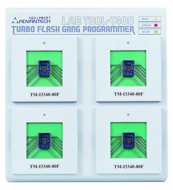
12 LABTOOL-T400 Profile 12
13 Device support summary The latest software: the software download and update from Flash memory: NOR, NAND, EEPROM and other flash technology Device data width: 8, 16, and 32 bits Maximum flash density support: flash 1G-bit with 256M-byte CF Card installed on board(standard offer), can be extend to 128G-bit with exchange higher density CF Card on the system. Please reference from AEC s website ( Specification: Socket and pin driver: 4 fully isolated adapter module with receptacle, over 10 M ohm resistance between each adapter module. Four DACs for V CC1, V CC2, V PP1, and V PP2 with 8 bit resolution. V CC1 and V CC2 range 0 V to 6.0 V, resolution 25 mv, maximum current 250 ma. V PP1 and V PP2 range 2.5 V to 18 V, resolution 80 mv, maximum current Overcurrent protection on all voltage sources, resolution 2mA, and maximum 500mA per source. Logic level 3.3 V to 1.2 V programmable by software Device Operation: Read, blank check, insertion /contact check, verify, check sum, erase chip, program, memory protect, edit buffer, configuration, load file, save file, project file load/save File format: Binary, Intel HEX, Intel extend HEX, Motorola S, HP64000ABS, TEK HEX, straight Hex. General Power adapter: 65W, 100 V AC to 240 V AC, Hz auto switch Output: DC 12V/3A and DC5V/7A Operation temperature: 5 to 45 C (41 to 113 F) Safety: CE & LVD certified Shipment Weight: 5.0 Kg without module adapter Using the LABTOOL-T400 Software Menus Accessing the menus can be done in two ways: Use the mouse and click on the menu option displayed at the top of the screen. A pull-down menu will appear, and you can select the option you desire by clicking on that option. If you do not have a mouse available, you can also use the keyboard to access the menus. Press [F10] to activate the main menu bar. Select the sub-menu that you want to use with the left and right arrow keys, and press <ENTER> to activate the sub-menu. Use the up and down arrows to select an option to execute. Press <ENTER> to execute the command. Hot-keys Most of the options available on the menus can also be executed by pressing the hot-key associated with that option. To see what the hot-key is for a certain option, look on the menu where the option is located. If a hot-key is available, it will be displayed next to the option name. 13
14 [Editor s Note: See Diagram in original manual!] Hot Keys Main Menu Sub Menu Device Information Information Line Statistics 14
15 2 CHAPTER Installation 15
16 Minimum PC System Requirements O.S.: Win 98/ME, Win 2000 SP4, and Win XP SP1/SP2. CPU: PII 750 and above RAM: 64 MB minimum, 512 MB recommended HD: 16 MB of free hard disk space. Interface: USB 1.1/2.0, USB2.0 recommended Installing the LABTOOL-T400 Software Insert the CD into the PC's CD-ROM E: Drive. It will execute the autorun to install LT-T400 software. In the file manager, you can select the E:\LTT400.EXE and hit Enter; it will create a directory called WLTT400 on your computer's C:\Programm Files\AEC path and will install the LABTOOL- T400 software in this directory. Following successful installation and then installing the LABTOOL-T400. Installing the LABTOOL-T Switch the LABTOOL-T400 off. 2. Install the LABTOOL-T400 software 3. Connect the power adapter to the LABTOOL-T Connect the LABTOOL-T400 to a USB port using the USB cable supplied. 5. Switch the LABTOOL-T400 on. 6. The O.S. automatically search USB device and customer press Continue during installing Updating the LABTOOL-T400 Software We provide quarterly formal releases of the LABTOOL-T400 software on our website. Monthly temporary releases are also available on our website. Please download releases from our website at: 16
17 3 CHAPTER Command Hierarchy 17
18 LABTOOL-T400 Command Hierarchy File (ALT-F) Save Buffer ALT-S Load File ALT-L Exit ALT-X Project (ALT-J) Save Project ALT-F1 Load Project ALT-F2 Device (ALT-D) Change ALT-C Mass Produce ALT-M Edit ALT-E Read ALT-R Blank Check ALT-B Program ALT-P Verify ALT-V Memory Prot/Prog Config Ctrl-P Erase Ctrl-E Configuration Ctrl-G Options (ALT-O) Operation F4 Module Options F5 Search Machine F6 Statistic F7 Diagnostics (ALT-I) Self-Test F8 18
19 4 CHAPTER Operation 19
20 LED Display on Each Socket Each of 4 adapter modules in the LABTOOL-T400 has a tri-color LED display to indicate the status of the socket. Read this section carefully to avoid damage to chips. Warning: Do not insert or remove a chip from a socket while the socket LED is yellow! LED color key Blank Green Yellow Red the adapter module is not active. the adapter module is active or the last operation result passed the adapter module is busy; don t do anything until the LED turns Green or Red. the last operation resulted in failure; the socket is active and awaiting another operation. Flashing LED, 5 Hz frequency. This mode only applies to insertion and contact checks of the chips in the socket. Flashing Green Flashing Yellow Flashing Red the chip passed the continuity check. the adapter module is active and waiting for a chip to be inserted. the chip failed the insertion/continuity check, due to poor contact, incorrect chip positioning, pin count mismatch, chip upside-down, pin short-circuit, or chip damage. File Commands Save Buffer Menu Hot-key File Save Buffer Alt-S This option is used to save the memory buffer to a file on the hard disk. Select a file (to overwrite!) using the mouse, or type the file name in the box provided. You can also type in a file spec. (e.g. *.hex, *.bin ) at the Name prompt. This will display all the files of the specified type, and you can then select the required file to overwrite. File Format Select the file format of the output file. Buffer Mode This mode functions as follows: Normal Every byte is written to the output file. Even(1 st of 2) Every Even byte is written to the output file. Odd(2 nd of 2) Every Odd byte is written to the output file. 20
21 1st byte of 4 This writes the bytes 1, 5, 9, 13,... into the output file. 2nd byte of 4 This writes the bytes 2, 6, 10, 14,... into the output file. 3rd byte of 4 This writes the bytes 3, 7, 11, 15,... into the output file. 4th byte of 4 This writes the bytes 4, 8, 12, 16,... into the output file. From Buffer Address A selected address is to be read from the buffer, fill in the address that will contain the first byte into this box. Buffer Size The size of the buffer to be read. Load File Menu Hot-key File Load File Alt-L This option loads a file from disk into the memory buffer. The type of files that can be loaded for a device depends on the device type. Select a file to load using the mouse, or type the filename in the box provided. You can also type in a file spec. (e.g. *.hex) at the Name prompt. This will display all the files of the specified type, and you can then select the required file to load. Auto Format Detected The software automatically detects the format of the file that is to be loaded. If the desired format of the file differs from the format detected, select the correct file format. From File This option indicates which bytes must be read in the input file. Select the required format. To Buffer This option indicates where the byte previously read is to be written. This enables you to 'build' the memory buffer from several files. From File Address If only a selected range is to be read from the input file, fill in the address that will contain the first byte into this box, and the size of the buffer to be read in Size. To Buffer Address If the data read is to be copied into a specific area of the buffer, fill in the starting address here. Buffer Size This box contains the buffer size. By default it is the same size as the device size. If you want to download a file into memory that is bigger than the active device, insert the size here (or in Options Operation Options). Clear Buffer Before Loading the file Four options are available during memory buffer data loading. The default option is to clear the buffer to its blank state prior to data loading. Disable 21
22 This option leaves the original buffer data unchanged, but then overwrites it with the contents of the newly loaded file. Clear buffer with blank state This option clears the buffer to the device blank state (using command 00 or FF, depending on device selection), then overwrites the buffer during file loading. Clear buffer with zeros (0x00) First clears the buffer of its contents using command 00, then overwrites the buffer with the new file contents Clear buffer with ones (0xFF) First clears the buffer of its contents using command FF, then overwrites the buffer with the new file contents. Exit to Windows Menu Hot-key File Exit Alt-X Quit the LABTOOL-T400 program and exit. Project Commands Save Project Menu Hot-key Project Save Project Alt-F1 This option saves the current setup of the LABTOOL-T400 software into a project file. The file includes devices selected, buffer data, operation options setup and device configuration setup. You can also attach a footnote to this project file. The project file acts as a macro, eliminating the need to go through each procedure during future programming sessions. Load Project Menu Hot-key Project Load Project File Alt-F2 This option loads the desired project file. After the project file has been loaded, you can immediately program the chip using the data and setup functions selected. Device Commands Change Device Menu Hot-key Device Change Alt-C This option is used to select a new device as the active device. It is important to select the correct device, as the algorithms used to program devices are device-specific. The following screen will appear: 22

23 Figure 4.1 Screen for selecting Change Device 1. Select the type of device that will be the active device. Mouse Click on 'All', 'EPROM' or 'Flash'. Keyboard Press TAB until the cursor is flashing in the 'Type' box. Use the up and down arrows to go to the appropriate type. Press the space bar to select the type. 2. Enter the part number, the manufacturer number, or parts of both in the 'Search' box. Mouse Click on 'Search'. Type in the characters. Keyboard Press TAB until the cursor flashes in the 'Search' box. Type in the known characters. All the devices that satisfy this partial information will be displayed. Use the mouse to select a device, and click 'OK'. If you are not using a mouse, use the TAB key to skip between the various screens, and use the arrow keys to move around in each screen. Mass-production Mode Menu Hot-key Device Mass Produce Alt-M 23

24 The LABTOOL-T400 is a mass-production programmer for manufacturing. When placed in mass production mode, all keyboard and mouse functions are disabled and the operator needs only to insert the chips into the sockets, wait until the green LED next to each socket lights up, remove the programmed chips and insert new chips. Anyone can do the job well without special training or skills. Since all keyboard and mouse functions are disabled, the possibility of errors being caused by pressing the wrong keys or changing the buffer's contents are eliminated. In mass production mode, the LABTOOL-T400 first performs an insertion test and an ID check on newly inserted chips. It then automatically programs the chip. In mass production, the LABTOOL- T400 can be set to either of two modes: standard mode or concurrent mode. In standard mode, LABTOOL-T400 programs the devices in all 4 adapter sockets at one time. Note: The insertion test must be enabled to use mass-production mode! Figure 4.2 Standard mass production mode screen An insertion timer is included for use with the insertion test. When a chip fails an insertion test and the insertion timer is disabled, the LABTOOL-T400 will alert the operator to the failure and require either that the problem be corrected or that the operator acknowledge the failure before continuing with programming. When a chip fails and the insertion timer is enabled, the LABTOOL-T400 waits the amount of time set into the insertion timer. This is to give the operator time to correct the error. If the error is not corrected in time, the error socket shuts down and all the devices in good sockets are programmed. The insertion timer default time is 5 seconds. 24
25 Editing the Buffer Menu Hot-key Device Edit Alt-E This function is used to edit the memory buffer. The memory buffer contains the last file downloaded from disk into memory. If no file has been downloaded from disk into memory since the LABTOOL-T400 was switched on, the memory buffer will contain "garbage". The screen that is displayed is dependent on the type of device that is currently active. The purposes of the buttons displayed are as follows: Radix This button controls the display of the memory address in Hex/decimal format. If the address is currently displayed in decimal format, clicking this button will convert and display the address in Hex. Fill This option is used to fill a block of memory with a specified value. It needs the starting address, the ending address and the value to be copied into this block of memory. Copy This function copies a block in memory to a new address. It requires the starting address, the ending address and the address the block must be copied to. Search This function searches for a specified "search-string". It requires input of the search-string to search for. Undo As you make changes to the memory buffer, the changes on the current page are highlighted. If you choose this option, it will reverse all changes made to the highlighted areas. As soon as the changed memory positions move off the screen, or get deselected by another command, the Undo command will not undo the changes. Blank checking a device Menu Hot-key Device Blank Check Alt-B This option checks if the active device is in its erased state. It will return a message stating "Device not blank!" at the first occurrence of data in the device. The address where the data is found will also be displayed. Reading a device Menu Hot-key Device Read Alt-R This option reads a master chip into the memory buffer for duplication of the master chip. Prior to executing this command, a master socket must be designated and the master chip inserted into the master socket. The default master socket is socket 0. Programming a device Menu Hot-key Device Program/Auto Alt-P 25

26 This option programs the active device with the contents of the memory buffer. When the programming is complete, verification will take place. The type of verification depends on the 'verification options' set in the Options Operation options menu. Figure 4-4 Programming progress screen Verifying a device Menu Hot-key Device Verify Alt-V This function compares the contents of the active device with the contents of the memory buffer. It will display an error message and the address if it finds an address where the data differs. It will also abort the process when this happens. 26

27 Figure 4-5 Device verification screen Memory Protect Menu Hot-key Device Memory Protect CTRL-P This function is a device-specific command; it appears on the main menu only after chips having this capability are selected. The function must be configured before use. When properly configured, it can be selected and will automatically set memory protection on the chips immediately after they have been programmed. Erasing a device Menu Hot-key Device Erase CTRL-E This function is a device-specific command; it appears on the main menu only after electronically erasable chips have been selected. The function can be used to erase a desired memory range from a chip. Configuration Menu Hot-key Device Configuration CTRL-G This function is a device-specific command for a single Flash chip with a software protect block, an option register, configure word and lock bit. The function must be configured before use. When used, 27

28 the memory protect configuration data will be burned into the chip's memory and will protect specified memory blocks. Figure 4-6 Example of device-specific configuration screen Options Device operation options Menu Options Operation options Hot-key F4 28

29 Figure 4-8 Example screen: Device-specific operation options The following options can be set: Start address, End address This is the start and the end address of the edit buffer. If you want to program a certain area of a device, you can change the start and end addresses accordingly. This option is only displayed when the device can be programmed in this way. When the end address is calculated, it divides the buffer size by (device-bits/8-bits). A 16 bit device, of which the buffer size is 80 (Hex), will therefore have an end address of 3F. When selecting a start or an end-address, you should align the buffer on the right boundary: singleword for 8-bit devices, double-word for 16-bit devices, etc. Erase start/end address This option is for electronically erasable Flash chips only. The default setting of this option will erase the entire chip. However, a user can specify ranges of blocks to be erased; data in the remaining blocks will be unchanged. A user should reference the chip data book or configuration menu when setting the ranges of blocks to be erased. Insertion Timer Enable/Disable When the insertion timer is disabled and an error is detected during insertion testing, the LABTOOL-T400 waits for the operator to either correct the error condition or to acknowledge and bypass the error. 29
30 When the insertion timer is enabled, the LABTOOL-T400 waits a specified period for the operator to correct the condition, and if no correction is made, shuts down the socket(s) reporting the error and completes programming of the remaining sockets. Insertion Timer This option sets the time-out interval for the insertion test. When the insertion timer is enabled and an insertion error is detected, if the operator fails to correct the problem within the interval set, the LABTOOL-T400 will automatically shutdown the error socket and complete programming of the remaining sockets. If multiple errors exist in different sockets and the operator corrects one of the sockets, the timer resets and waits the specified time for each succeeding error. Time-out intervals can be set from 1 to 999 seconds. The default value is 5 seconds. Insertion Test This option performs the device-insertion check of the chips in the sockets. The insertion check includes poor pin contact, pin count mismatch (the pin count of the chip designated in the software does not match the pin count of the actual chip in the socket), device in wrong position, device upside-down, short-circuit between pins, and chip damage. Results are displayed at each socket's LED. Device ID Check This option performs a device signature and manufacturer match test. With the chip selected and plugged into a socket, LABTOOL-T400 checks the device ID and displays the results of each check on the LED display. Verify Passes Checking this option will instruct the LABTOOL-T400 to perform device verification with the buffer data when programming is complete. When verify passes is enabled, one of the three verify options (as described below) must be set. Verifying Options The following three options are available for verification of data retention following programming: verify twice with 5% V CC, verify twice with 10% V CC, and verify once with V CC. These options will only be enabled if the 'Verify passes' option (see above) is enabled. ( ) Twice V CC ± 5 % When this option is selected, the LABTOOL-T400 will do two verify passes on the device: one using V CC + 5%, the other V CC - 5%. Example: IF V CC is 3.3 V, the LABTOOL-T400 will do one verify pass using a V CC of V, and one using a V CC of V. ( ) Twice V CC ± 10 % When this option is selected, the LABTOOL-T400 will do two verify passes on the device: one using V CC + 10%, the other V CC - 10%. Module options Menu Options Module options Hot-key F5 30

31 This option is used to select the master module location (default module 0), and enable/disable the module. Figure 4-9 Master Module selection, Active Module selection Search Machine Menu Options Search Machine Hot-key F6 This option is used to search LABTOOL-T400 in which USB port and software. When you turn the LABTOOL-T400 off and then on, you have to use this option to search an unassigned LABTOOL- T400 for controlled by present software. 31

32 Statistic Figure 4-10 After Search Machine selection LABTOOL-T400 can keep track of chip programming failures. The lower right-hand corner of the Run Time Viewer screen contains two entries: Current Quantity and Total Fail. These quantities automatically increment for every chip LABTOOL-T400 attempts to program, and for every programming failure. Failures counted include chips that fail device ID check, blank check, verify pass, protect, and unprotect. The user can input a target quantity of chips to be programmed in a production run, and an allowable number of failures. An alarm feature can be set so that when the target quantity or the allowable failures is reached, an alarm message is displayed on the screen to alert the operator. Menu Hot-key Options Statistic F7 This command controls the setting of the Statistic Option. Select the command using the mouse or tab key, or the hot-key Alt-T. The screen shown below will appear. Use the mouse or tab between screen entries. Fill in the desired quantities for Target Quantity and Maximum Fail, and indicate your choice for alarm enabling or disablement. Select the OK button and press enter to confirm your selections. Click the Reset button to set statistic parameters to default. 32

33 Diagnostics Commands Figure-11 Statistic option selection screen Self Test Menu Hot-key Diagnostics Self Test F8 This option is used to self test the LABTOOL-T400. Remove all devices from the modules and then press Enter to start self test function. In the C:\Program Files\AEC\WLTT400 folder, there is a serial number text file of the LABTOOL-T400 (e.g. AE txt) after the self test function. The file includes system information and hardware tested result. If you need to update or upgrade or repair the LABTOOL- T400, please send the text file (e.g. AE txt) to us. We will do our best service for you. 33

34 Figure-12 In the Self Test Processing screen 34
35 5 CHAPTER Using Adapters 35
36 Adapter requirements The LABTOOL-T400 supports 48-TSOP, 56-pin TSOP, ufbga, uvfgba, ubga, BGA, ect. packages. You will need to order an adapter for your chip package. You can order the following available adapters to fit your needs. Other adapters will become available after release of new chips. We have a device list and adapter note, please reference T400_ALL.pdf 36
37 A APPENDIX Error Messages 37
38 Error Messages This function is not supported in demo mode! When the LABTOOL-T400 is not activated, some functions may be inhibited. Illegal range of erase address setting! Retry again! The address range for an erase command must match the sector edge. Time-Out error! The LABTOOL-T400 does not respond when the system times out. Cannot open file : XXXXXXXX! The file was not found or a disk error occurred. Device ID Code unmatched! The current chip's ID will be displayed. File write error! Illegal file name or disk error. The LABTOOL-T400 detected an error when writing a file to disk. Check that there is enough space on the disk to hold the file. Also check that the disk is not write-protected. This might happen on a network if you are a user that does not have rights to the directory you want to save the file to. Use another directory or disk. File read incomplete! The user break.file format was unmatched or a disk error occurred during file reading. LABTOOL-T400 not found, Do you want to retry? The LABTOOL-T400 software does not detect the LABTOOL-T400 on one of the USB ports. Press enter to retry or press F6 to search machine. Press Esc to enter demo mode. Make sure the power on the LABTOOL-T400 is on. Also check the parallel connection between the PC and the LABTOOL-T400. If the LABTOOL-T400 shares the USB port with another device, remove the other device or move the LABTOOL-T400 to its own port. 38
39 LABTOOL-T400 power off or disconnected from PC! The LABTOOL-T400 software does not detect the LABTOOL-T400 on one of the USB ports. Make sure the power on the LABTOOL-T400 is on. Also check the USB connection between the PC and the LABTOOL-T400 and between the PC and the USB port. If the LABTOOL-T400 shares the USB port with another device, remove the other device or move the LABTOOL-T400 to its own port. Other Error Messages The following list of error messages uses the code XXXX, where XXXX can be Read; Verify/ Blank Check; Program; Erase; or Memory Protect. Aborted has the same meaning as user break. XXXX Aborted! XXXXX error found! XXXX error on Module X Address XXXXh! 39
40 B APPENDIX Troubleshooting 40
41 Q&A Q1: How to install the LABTOOL-T400 software? Ans: Step1. Install the LABTOOL-T400 software. If you do not have the software, and you can download it from our website( If you have installed the software, skip this step. Step2. Turn the LABTOOL-T400 power on. Step3. Select Start Control Console System Hardware Device Manager and you will see the AEC LabTool-T400 Turbo Flash Gang Programmer. Step4. Run the LABTOOL-T400 software. Note : Recommended O.S. in your PC (1) Windows XP + SP1 (2) Windows XP + SP2 (3) Windows SP4 41
42 Step1. Install the LABTOOL-T400 software. If you do not have the software, and you can download it from our website( If you have installed the software, skip this step. Fig1-1 : Extracting Fig1-2 : Starting InstallShield Wizard Fig1-3 : Installing 42
43 Fig1-4 : Press Next Fig1-5 : Press Install 43
44 Fig1-6 : Installing Fig1-7 : Press Finish 44
45 Step2. Turn the LABTOOL-T400 power on. You will see the messages Fig2-1: Select No, not this time and then press Next Fig2-2 : Select Install the software automatically (Recommended) and then press Next 45

46 Fig2-3 : Installing Fig2-4 : Press Continue Anyway. If you select the other button, the O.S. will has a wrong!usb Device in your PC. 46

47 Fig2-5 : Press Finish 47

48 Step3. Select Start Control Console System Hardware Device Manager and you will see the AEC LabTool-T400 Turbo Flash Gang Programmer. Fig3-1 : Press Device Manager Fig3-2 : You will see the AEC LabTool-T400 Turbo Flash Gang Programmer below your Universal Bus controllers. 48

49 Step4. Run the LABTOOL-T400 software. Fig4-1: Select Start -> All Programs -> Advantech LabTool -> LabTool- T400 Fig4-2 : After run the LabTool-T400 software, you will see your LabTool-T400 serial number with USB interface. 49
50 Q2: The O.S. can t find the LT-T400 after power on. Ans: Step1. Install the LABTOOL-T400 software. If you do not have the software, and you can download it from our website( If you have installed the software, skip this step. Step2. Turn the LABTOOL-T400 power on. Step3. Select Start Control Console System Hardware Device Manager. You will see an! USB Device in your PC. Step4. Uninstall the USB Device Step5. Turn the LABTOOL-T400 power off. Step6. Turn the LABTOOL-T400 power on and then the OS found out a new USB device from your USB interface. Step7. Select Start Control Console System Hardware Device Manager and you will see the AEC LabTool-T400 Turbo Flash Gang Programmer Step8. Run the LABTOOL-T400 software. Note : Recommended O.S. in your PC (4) Windows XP + SP1 (5) Windows XP + SP2 (6) Windows SP4 50

51 Step1. Install the LABTOOL-T400 software. If you do not have the software, and you can download it from our website( If you have installed the software, skip this step. Fig1-1 : Extrating Fig1-2 : Starting InstallShield Wizard Fig1-3 : Preparing 51

52 Fig1-4 : Press Next Fig1-5 : Press Install 52

53 Fig1-6 : Installing Fig1-7 : Press Finish 53

54 Step2. Turn the LABTOOL-T400 power on. Step3. Select Start Control Console System Hardware Device Manager. You will see the! USB Device in your PC. Fig3-1 : Press Device Manager Fig3-2 : The!USB Device may be below Universal Serial Bus controllers or Other devices 54


55 Step4. Uninstall the USB Device Fig4-1 : Press the right button of the mouse and select Uninstall. Fig4-2 : Press OK 55

56 Fig4-3 : Device Manager after uninstalling 56


57 Step5. Turn the LABTOOL-T400 power off. Step6. Turn the LABTOOL-T400 power on and then the OS found out a new USB device from your USB interface. Fig6-1 : Select No, not this time and press Next Fig6-2 : Select Install the software automatically (Recommended) and then press Next 57

58 Fig6-3 : Installing Fig6-4 : Press Continue Anyway. If you select the other button, the O.S. will has a wrong!usb Device in your PC. 58
59 Fig6-5 : Press Finish 59


60 Step7. Select Start Control Console System Hardware Device Manager and you will see the AEC LabTool-T400 Turbo Flash Gang Programmer Fig7-1 : Press Device Manager Fig7-2 : You will see the AEC LabTool-T400 Turbo Flash Gang Programmer below your Universal Bus controllers. 60
61 Step8. Run the LABTOOL-T400 software. Fig8-1: Select Start -> All Programs -> Advantech LabTool -> LabTool- T400 Fig8-2 : After run the LabTool-T400 software, you will see your LabTool-T400 serial number with USB interface. 61
GANGSTAR PRO-848 GANG PROGRAMMER USER MANUAL
 GANGSTAR PRO-848 GANG PROGRAMMER USER MANUAL LOGICAL DEVICES INC. PO BOX 8400 DENVER, CO 80201 TEL: 303-861-8200 FAX: 303-813-9019 WWW.LOGICALDEVICES.COM Copyright Notice This document is copyrighted,
Dataman-S6 - User's Manual. Dataman-S6 Compact USB Programmer User's Manual
 Dataman-S6 Compact USB Programmer User's Manual Contents Chapter 1 Product Description 1-1 Introduction 1-2 Safety Information 1-3 Precautions 1-4 Operating System, Hardware Requirements 1-5 Accessories
Intelligent Universal Programmer User s Manual
 M1881UXP Intelligent Universal Programmer User s Manual Copyright Notice This document is copyrighted, 2000, 2001, 2002 by MINATO ELECTRONICS INC. All rights are reserved. MINATO ELECTRONICS INC. reserves
ACT-HDC11FH/ ACT-HDC13FH 1 to 1(3) HDD Duplicator. User s Manual. Ver: 1.1 ACT
 HDD Duplicator. User s Manual. Ver: 1.1 ACT") ACT-HDC11FH/ ACT-HDC13FH 1 to 1(3) HDD Duplicator User s Manual Ver: 1.1 Attention: It takes over 5 seconds to power on after shutdown otherwise the system may operate abnorrmally. ACT ACT-POWER COMPUTER
ACT-HDC11FH/ ACT-HDC13FH 1 to 1(3) HDD Duplicator User s Manual Ver: 1.1 Attention: It takes over 5 seconds to power on after shutdown otherwise the system may operate abnorrmally. ACT ACT-POWER COMPUTER
USB Keyboard and Mouse Console Switch User Manual
 USB Keyboard and Mouse Console Switch User Manual (DS-16100) 1 INTRODUCTION The USB Keyboard and Mouse Console Switch provides a user to control two computers and associated display screens by using a
CHAPTER. General Information
 CHAPTER 1 General Information 1 Introduction The DATAMAN-48XP is an intelligent high performance, PC-based universal programmer that works through your PC s parallel port. It features a 48-pin ZIF socket
XELTEK Superpro E Series
 User s Guide XELTEK Superpro 6000-6000E Series Ultra-Fast, Stand-Alone, 144pin Programmer of the Future XELTEK 1296 Kifer Rd. Unit 605 Sunnyvale, CA 94086 Tel: (408) 530-8080 Fax: (408) 530-0096 www.xeltek.com
OPERATION MANUAL. MV-410HS Layout Editor. Version higher. Command
 OPERATION MANUAL MV-410HS Layout Editor Version 3.0 - higher Command Command Table of Contents 1. Setup... 1 1-1. Overview... 1 1-2. System Requirements... 1 1-3. Operation Flow... 1 1-4. Installing MV-410HS
GANG Programmer for flash micro computers. User s Manual. TESSERA Technology INC. Third Edition September
 GANG Programmer for flash micro computers User s Manual TESSERA Technology INC. Third Edition September 2008-1 - Table of Contents Chapter 1 Summary 3 1.1 System Configuration 4 Chapter 2 Installation
 WWW.LOGICALDEVICES.COM Table of Contents Welcome... 6 Feature Highlights... 6 User Manual Organization... 7 Chapter 1 General Description... 8 Introduction to XPRO... 8 Package Contents... 8 Software Features...
MP8011A. Gang Programming System
 MP8011A Gang Programming System User s Manual Copyright 2000 SofTec Microsystems DC00242 SofTec Microsystems via Roma, 1 33082 Azzano Decimo (PN) ITALY Tel: (+39) 0434 640 729 Fax: (+39) 0434 632 695 E-mail
FLASH PROGRAMMER FP-8903 VER 2.00 USER S MANUAL
 FLASH PROGRAMMER FP-8903 VER 2.00 USER S MANUAL FP8903 V2.00 DOC R.2.0 1 TABLE OF CONTENTS SECTION CONTENTS PAGE 1 INTRODUCTION 1.1 MANUAL CONTENTS 03 1.2 PROGRAMMER AND ACCESSORIES 03 2 FEATURES 04 3
ADAM-5511 Quick Start
 ADAM-5511 Quick Start Support Firmware 1.01 or above Copyright Notice This document is copyrighted 2001 by Advantech Co., Ltd. All rights are reserved. Advantech Co., Ltd., reserves the right to make improvements
XELTEK Superpro 7500 Series
 User's Guide XELTEK Superpro 7500 Series Ultra Fast, Stand Alone, 144pin Programmer of the Future XELTEK 1296 Kifer Rd. Unit 605 Sunnyvale, CA 94086 Tel: (408) 530 8080 Fax: (408) 530 0096 www.xeltek.com
PanelViewt 1200 Transfer Utility User Manual
 User Manual Solid state equipment has operational characteristics differing from those of electromechanical equipment. Safety Guidelines for the Application, Installation and Maintenance of Solid State
ACT-HDC15SPD 1 to 5 HDD Duplicator. User s Manual. Ver: 1.00 ACT
 1 to 5 HDD Duplicator User s Manual Ver: 1.00 Attention: It takes over 5 seconds to power on after shutdown otherwise the system may operate abnorrmally. ACT ACT-POWER COMPUTER TECHNOLOGY CORP. http://www.honetek.com
XELTEK Superpro 7000 Series
 User s Guide XELTEK Superpro 7000 Series Ultra Fast, Stand Alone, 144pin Programmer of the Future XELTEK 1296 Kifer Rd. Unit 605 Sunnyvale, CA 94086 Tel: (408) 530 8080 Fax: (408) 530 0096 www.xeltek.com
Multifunctional Presentation Kit YP-100
 Multifunctional Presentation Kit YP-00 E User s Guide Be sure to read the precautions in the separate Getting Started Guide. The Getting Started Guide also includes information about connecting the YP-00
FWA-6280A User Manual 1. FWA-6280A User Manual
 1 Copyright Notice This document is copyrighted, 2005. All rights are reserved. The original Manufacturer reserves the right to make improvements to the products described in this manual at any time without
NVR-CV. Network Video Recorder Hot-Swappable Tray for 3.5 HDD x 4 or 2.5 HDD x 4 Gigabit Ethernet x 2 COM x 2, USB2.0 x 6. VGA x 1, DVI-D x 1
 Netw ork Video Recorder N V R - CV Network Video Recorder Hot-Swappable Tray for 3.5 HDD x 4 or 2.5 HDD x 4 Gigabit Ethernet x 2 COM x 2, USB2.0 x 6 VGA x 1, DVI-D x 1 Manual 1st Ed. Oct. 2013 Copyright
Remote Watchman Device Server User Manual
 Remote Watchman Device Server User Manual Software Version 4.0 Manual P/N 071-0043 Rev 8 September 29, 2016 Copyright 2000-2016 Sensorsoft Corporation, All rights reserved. Sensorsoft, SCOM and Remote
READ THIS INFORMATION FIRST Product: Remote IO Manager Software Release Remote IO Manager w/ Cable. Remote IO Manager Branding Toolkit.
 May 16, 2002 IMPORTANT PRODUCT INFORMATION READ THIS INFORMATION FIRST Product: Remote IO Manager Software Release 2.03 IC641CFG100E IC641CFG101E IC640CFG200E Remote IO Manager. Remote IO Manager w/ Cable.
Quick Setup & Getting Started
 Quick Setup & Getting Started HP Compaq Business PC Copyright 2007 Hewlett-Packard Development Company, L.P. The information contained herein is subject to change without notice. Microsoft, Windows, and
DVP-7020BE 16 Channel PCI-bus Surveillance Capture card
 DVP-7020BE 16 Channel PCI-bus Surveillance Capture card Copyright This documentation and the software included with this product are copyrighted in 2006 by Advantech Co., Ltd. All rights are reserved.
ALL-200G. Universal Gang Programmer. User s Manual
 ALL-200G Universal Gang Programmer User s Manual Apr. 2014 Caution : USB Interface Compatibility For USB 2.0 compatibility, your computer should work with the following operation system or later revision
Wavy for PLZ-4W Ver. 4.0
 Operation Manual Sequence Creation Software Wavy for PLZ-4W Ver. 4.0 Version 4.0 Prepared: June 21, 2006 KIKUSUI ELECTRONICS CORPORATION 1/35 Note Before contacting us to request repair, inspection, or
Programmer. User Guide
 Programmer User Guide Trademarks & Copyright Windows and Windows NT are registered trademarks of Microsoft Corporation. MCS-51 and Pentium are registered trademarks of Intel Corporation. AVR is registered
Texas Instruments TUSB8040 EEPROM Programming Utility. User s Guide
 Texas Instruments TUSB8040 EEPROM Programming Utility User s Guide Program Overview The TUSB8040 EEPROM Programmer enables the user to program an onboard EEPROM (if present) via the Texas Instruments TUSB8040
Express5800/320La System Release Notes
 System Release Notes Express5800/320La System Release Notes PN: 455-01623-003 Proprietary Notice and Liability Disclaimer The information disclosed in this document, including all designs and related materials,
Full User Manual and Quick Start Guide
 Full User Manual and Quick Start Guide 2 W hile every precaution has been taken in the preparation of this manual, we assume no responsibility for errors or omissions. Neither, is any liability assumed
Advin Systems Inc. PILOT DEVICE PROGRAMMERS User's Manual. Legal Notices. Life Support Policy. Warranty Information
 Legal Notices Advin Systems Inc. PILOT DEVICE PROGRAMMERS User's Manual The information contained in this manual has been carefully checked and is believed to be accurate and complete at the time of printing.
CDL-160ETH. Ethernet and USB to HDMI Converter. Operation Manual CDL-160ETH
 CDL-160ETH Ethernet and USB to HDMI Converter Operation Manual CDL-160ETH Disclaimers The information in this manual has been carefully checked and is believed to be accurate. Cypress Technology assumes
How to Update NN3D to v2.07 (Combo Update) MFDBB
 MFDBB") How to Update NN3D to v2.07 (Combo Update) MFDBB 1. NN3D v2.07 Update Introduction MFDBB The combo update for the MFDBB requires a USB Jump Drive (USB flash memory stick). Additionally, a USB KEYBOARD
How to Update NN3D to v2.07 (Combo Update) MFDBB 1. NN3D v2.07 Update Introduction MFDBB The combo update for the MFDBB requires a USB Jump Drive (USB flash memory stick). Additionally, a USB KEYBOARD
OS Installer. Installation Instructions
 OS Installer These instructions are only relative to Digital X Bus X.200 owners needing to completely clean out their internal hard drive and re-install the entire operating system and the latest Digital
Finding information on your computer
 Important Be sure to create recovery discs immediately after your computer is ready for use because there are no recovery discs provided with the computer. For instructions on how to create the recovery
XERA Kitchen Display Server User Manual. PUBLISHED BY Aldelo, LP 6800 Koll Center Parkway, Suite 310 Pleasanton, CA 94566
 XERA Kitchen Display Server User Manual 3 PUBLISHED BY Aldelo, LP 6800 Koll Center Parkway, Suite 310 Pleasanton, CA 94566 Copyright 1997-2014 by Aldelo, LP. All rights reserved. No Part of the contents
8 ports/16 ports USB/PS/2 Combo-KVM Switch
 8 ports/16 ports USB/PS/2 Combo-KVM Switch Manual DS-23200-2 DS-23300-2 PRODUCT MODEL LIST Model DS-23200-2 DS-23300-2 Specification 8 input (USB & PS/2), 1 output (USB), Supporting cascade & hub. 16 input
Fujitsu STYLISTIC Q Series
 Fujitsu STYLISTIC Q Series BIOS Guide STYLISTIC Q Series Model: Q552 Document Date: 5252012 Document Part Number: FPC58-3061-01 FUJITSU AMERICA, INC. 1 STYLISTIC Q552 BIOS Q Series BIOS BIOS SETUP UTILITY
3700 SERIES USER MANUAL
 SAFETY GUIDE This manual contains the precautions necessary to ensure your personal safety as well as for protection for the products and the connected equipment. These precautions are highlighted with
DRAWings 8 and Wings modular 8 Embroidery Software INSTALLATION GUIDE
 DRAWings 8 and Wings modular 8 Embroidery Software INSTALLATION GUIDE We thank you for purchasing DRAWings 6 and Wings modular 5 software. We are committed to providing you with the most innovative technology.
Troubleshooting & Repair
 Chapter Troubleshooting & Repair 6.1 Introduction This chapter provides the most common problem encountered with the M785 notebook computer and some troubleshooting means. Some of the common problems are:
Programming Manual KX-TVA50 KX-TVA200. Voice Processing System. Model No.
 Programming Manual Voice Processing System KX-TVA50 KX-TVA200 Model No. Thank you for purchasing a Panasonic Voice Processing System. Please read this manual carefully before using this product and save
Admin Guide. LabelShop 8
 Admin Guide LabelShop 8 Administrator s guide DOC-OEMCS80-AG-US-02/03/06 The information in this manual is not binding and may be modified without prior notice. Supply of the software described in this
Getting Started. HP Business PCs
 Getting Started HP Business PCs Copyright 2013 Hewlett-Packard Development Company, L.P. The information contained herein is subject to change without notice. Windows is a U.S. registered trademark of
ThinkPad Dock, ThinkPad Dock II. User s Guide
 ThinkPad Dock, ThinkPad Dock II User s Guide ThinkPad Dock, ThinkPad Dock II User s Guide ATTENTION Before installing this product, refer to the documentation that comes with your computer. Note Be sure
Programming Manual KX-TVA50 KX-TVA200. Voice Processing System. Model
 Voice Processing System Programming Manual Model KX-TVA50 KX-TVA200 Thank you for purchasing a Panasonic Voice Processing System. Please read this manual carefully before using this product and save this
DATA VIEWER FOR PAPERLESS RECORDER
 Instruction Manual DATA VIEWER FOR PAPERLESS RECORDER TYPE: PHR/PHW INP-TN513550i-E WARNING If an error or improper operation occurs in our product, or customer-made programs should be found defective,
Intel Server RAID Controller U2-1 Integration Guide For Microsoft* Windows NT* 4.0
 Intel Server RAID Controller U2-1 Integration Guide For Microsoft* Windows NT* 4.0 Revision 1.0 February 2000 Revision History Revision Revision History Date 1.0 Initial Release 02/10/00 Intel Corporation
Programming and Evaluation Tool for Serial EEPROMs
 EasyPro 3.2 Evaluation Board User's Manual EVAL BOARD USER S MANUAL Programming and Evaluation Tool for Serial EEPROMs What is EasyPRO? EasyPRO is an easy-to-use, software-driven device programmer that
Setup support for RAMCHECK. Extensive, context-sensitive On-Line Help and Tutorials. HARD DISK INSTALLATION:
 RAMCHECK OWNER S MANUAL While RAMCHECK is a stand-alone unit, the product includes the RAMCHECK PC Communications programs that allow you to upgrade your RAMCHECK s flash EPROM from our Web site (www.innoventions.com).
The following documents are included with your Sony VAIO computer.
 Documentation The following documents are included with your Sony VAIO computer. Printed Documentation Quick Start Guide Describes the process from unpacking to starting up your VAIO. Troubleshooting and
Fujitsu LifeBook N Series
 Fujitsu LifeBook N Series BIOS Guide LifeBook N Series Models: N6400 Document Date: 07/16/2007 Document Part Number: FPC58-1702-01 FUJITSU COMPUTER SYSTEMS CORPORATION 1 LifeBook N Series BIOS N Series
User Manual A08. User Manual
 A08 TABLE OF CONTENTS TABLE OF CONTENTS... 1 1. INTRODUCTION... 2 1.1. Key Features... 3 1.2. OS Requirement... 4 1.3. Specification... 4 1.4. Packing List... 4 2. OVERVIEW... 5 2.1. LED Definition...
Fujitsu Stylistic ST6000 Series
 Fujitsu Stylistic ST6000 Series BIOS Guide Stylistic Series Model: ST6012 Document Date: 12/01/2008 Document Part Number: FPC65-4369-01 FUJITSU COMPUTER SYSTEMS CORPORATION 1 Stylistic ST Series BIOS ST
DATA PROJECTOR XJ-H1650/XJ-H1750 XJ-ST145/XJ-ST155
 DATA PROJECTOR XJ-H1650/XJ-H1750 XJ-ST145/XJ-ST155 E Data Projector USB Function Guide Be sure to read the precautions in the separate Setup Guide. Be sure to keep all user documentation handy for future
Que! USB Floppy Disk Drive Installation Guide
 Que! USB Floppy Disk Drive Installation Guide status indicator: The status indicator LED lights up to indicate that the floppy disk drive is accessing a floppy disk. disk door: The disk door prevents dust
Serial ATA PCI RAID Quick Installation Guide
 Serial ATA PCI RAID Quick Installation Guide Introducing the Serial ATA PCI RAID The Serial ATA PCI RAID is an ultra high-speed two channel Serial ATA controller board for use in Pentium-class computers.
HP Travel Phone User s Guide
 HP Travel Phone User s Guide Version 1.0 Copyright 2007 Hewlett-Packard Development Company, L.P. The information contained herein is subject to change without notice. The only warranties for HP products
XP-ROM Operation Manual (V2.00)
") XP-ROM Operation Manual (V2.00) May. 06 Table of Contents 1. Overview 1 1.1 connection between PC and Programmer 1 1.2 Installation of XPROM 2 1.3 Start up display 2 1.4 Explanation of each screen 3 1.5
XP-ROM Operation Manual (V2.00) May. 06 Table of Contents 1. Overview 1 1.1 connection between PC and Programmer 1 1.2 Installation of XPROM 2 1.3 Start up display 2 1.4 Explanation of each screen 3 1.5
Simplex 4190 TrueSite Workstation (TSW) Software Upgrade Instructions
 Software Upgrade Instructions") Simplex 4190 TrueSite Workstation (TSW) Software Upgrade Instructions Introduction This publication describes the software upgrade procedure for the Simplex 4190 TrueSite Workstation (TSW). Inspecting
Simplex 4190 TrueSite Workstation (TSW) Software Upgrade Instructions Introduction This publication describes the software upgrade procedure for the Simplex 4190 TrueSite Workstation (TSW). Inspecting
Data setting software MEXE02
 HM-40143 Data setting software MEXE02 OPERATING MANUAL Before Use Thank you for purchasing an Oriental Motor product. This operating manual describes product handling procedures and safety precautions.
Pin-Master 48. Everything you need from a development programmer
 Pin-Master 48 Everything you need from a development programmer Device Types Over 8750 device types Includes 3V parts EPROMs, EEPROMs, FLASH EPROMs and Emulators up to 48 pins PLDs and FPGAs including
Orbit USB Interface Module. User Manual
 Orbit USB Interface Module User Manual Information in this document is subject to change without notice. Companies, names and data used in examples herein are fictitious unless noted otherwise. No part
Silicon Sculptor Software v4.7 for Silicon Sculptor II and Silicon Sculptor 3. Programmers User s Guide
 Silicon Sculptor Software v4.7 for Silicon Sculptor II and Silicon Sculptor 3 Programmers User s Guide Actel Corporation, Mountain View, CA 94043 2008 Actel Corporation. All rights reserved. Printed in
PCI bit Digital Input/ Output Card for PCI Bus. User s Manual
 PCI-1751 48-bit Digital Input/ Output Card for PCI Bus User s Manual Copyright This documentation and the software included with this product are copyrighted 1998 by Advantech Co., Ltd. All rights are
WizISP Program User Guide for W7100
 WizISP Program User Guide for W7100 version 0.9βeta 2008 WIZnet Co., Inc. All Rights Reserved. For more information, please visit our website at http://www.wiznet.co.kr Copyright 2009 WIZnet Co., Inc.
PS-9000 User s Manual UK English
 PS-9000 User s Manual UK English Introduction Thank you for purchasing PS-9000 print server. This manual provides complete information on how to set up and use PS-9000 safely. Please read this manual carefully
Operating Instructions
 Operating Instructions For Digital Camera PC Connection QuickTime and the QuickTime logo are trademarks or registered trademarks of Apple Computer, Inc., used under license. Connection with the PC Offers
ZCRMZNICE01ZEMG Crimzon In-Circuit Emulator
 Quick Start Guide QS006602-0408 Introduction Zilog s ZCRMZNICE01ZEMG Crimzon (ICE), shown in Figure 1, provides Crimzon chip family emulation with a Trace and Event system for program debugging using Zilog
Longshine Technologie Europe GmbH LCS-MFP101-2 Multifunction Printserver
 Longshine Technologie Europe GmbH LCS-MFP101-2 Multifunction Printserver www.longshine.de TABLE OF CONTENTS COPYRIGHT...2 1. INTRODUCTION...3 PRODUCT OVERVIEW...3 COMPONENTS AND FEATURES...3 HARDWARE INSTALLATION...3
TABLE OF CONTENTS COPYRIGHT INTRODUCTION...3 PRODUCT OVERVIEW...3 COMPONENTS AND FEATURES...3 HARDWARE INSTALLATION
 TABLE OF CONTENTS COPYRIGHT...2 1. INTRODUCTION...3 PRODUCT OVERVIEW...3 COMPONENTS AND FEATURES...3 HARDWARE INSTALLATION...3 2. MFP SERVER INSTALLATION...5 PREPARATION...5 CONFIGURATION SOLUTION TABLE...5
Application Note: AN0103. On-Board SPI programming with DediProg tools: Designer version
 4F., No.7, Ln. 143, Xinming Rd., Neihu Dist., Taipei City 114, Taiwan Application Note: AN0103 On-Board SPI programming with DediProg tools: Designer version DediProg Page 1/25 December 09 Table of content:
How to install the software of ZNS8022
 How to install the software of ZNS8022 1. Please connect ZNS8022 to your PC after finished assembly. 2. Insert Installation CD to your CD-ROM drive and initiate the auto-run program. The wizard will run
Bose ControlSpace Designer Software. User Guide
 Bose ControlSpace Designer Software User Guide 2005 Bose Corporation. No part of this work may be reproduced, modified, distributed or otherwise used without prior written permission. Contents Introduction
Public Software Patch Release Notes
 Public Software Patch Release Notes Software version: 2.1.9945 Released on: 13 July 2012 Supersedes version: 2.1.9596 Released on: 7 May 2012 Software Release Notification Application installation packages
USB to Serial Converter User s Guide
 USB to Serial Converter User s Guide Important Note! In order to minimize possible installation problems and/or resource conflicts: Read Me First! About This User s Guide This User s Guide is designed
Installation. Installation 1
 Installation 1 Installation The SP35 printer is easy to install and use. It is also flexible; you can connect and use it in many different ways. Most often, one printer is connected to one PC. However,
SomaticView Version 1.0
 SomaticView Version 1.0 User's Guide Technology that counts This page was intentionally left blank SomaticView A part of the NucleoCounter SCC-100 system Manual No. 991-0201 (English) Version 1.0 March
3980xpi/3980/3900 V8.2 User Notes
 3980xpi/3980/3900 V8.2 User Notes Contents What s New in Version 8.2........................................ 2 Reminders.................................................... 5 Determining if 3900 Has Hard
Wavy for PAX Ver. 4.0
 Operation Manual Sequence Creation Software Wavy for PAX Ver. 4.0 SPEC70289 Version 4.0 Prepared: June 21, 2006 KIKUSUI ELECTRONICS CORPORATION 1/34 Contents Note Before contacting us to request repair,
Getting Started With the CCPilot VI and QuiC
 Page 1 of 24 Getting Started With the CCPilot VI and QuiC Page 2 of 24 Table of Contents Purpose... 3 What You Will Need... 4 Install the QuiC Tool... 6 Install the QuiC Runtime... 7 Basics of the QuiC
Revision: 0.30 June Intel Server Board S1200RP UEFI Development Kit Firmware Installation Guide
 Revision: 0.30 June 2016 Intel Server Board S1200RP UEFI Development Kit Firmware Installation Guide Intel Server Board S1200RP UEFI Development Kit Firmware Installation Guide INFORMATION IN THIS DOCUMENT
500 Series Installation Guide
 500 Series Installation Guide Revision 1.9 September, 2010 Disclaimer: The specifications in this document are subject to change without notice. All trademarks mentioned in this document are the property
Fujitsu LifeBook A Series
 Fujitsu LifeBook A Series BIOS Guide LifeBook A Series Model: A6030 Document Date: 06/06/2007 Document Part Number: FPC58-1698-01 FUJITSU COMPUTER SYSTEMS CORPORATION 1 LifeBook A Series BIOS A Series
Infrared Docking Station
 For uploading voice files to Enterprise Express Infrared Docking Station Operating Instructions Contents Overview...1 What s In The Box...1 System Requirements...1 Where to Go From Here...3 Getting Help...4
Trace Debug Tools Version 1.2 Installation Guide
 Trace Debug Tools Version 1.2 Installation Guide Copyright 2000-2002 ARM Limited. All rights reserved. Proprietary Notice Words and logos marked with or are registered trademarks or trademarks owned by
Application Note: AN0106. On-Board SPI Programming with Dediprog tools: End User Version
 4F., No.7, Ln. 143, Xinming Rd., Neihu Dist., Taipei City 114, Taiwan Application Note: AN0106 On-Board SPI Programming with Dediprog tools: End User Version (This document is provided to help users who
PCL channel Isolated Digital I/O Card
 PCL-730 32-channel Isolated Digital I/O Card Copyright This documentation is copyrighted 1996 by Advantech Co., Ltd. All rights are reserved. Advantech Co., Ltd. reserves the right to make improvements
CS-64U. User Manual
 User Manual CS-64U Read this guide thoroughly and follow the installation and operation procedures carefully in order to prevent any damage to the units and/or any devices that connect to them. This package
FUJITSU FLASH MCU Programmer for F 2 MC-8FX Specifications
 FUJITSU FLASH MCU Programmer for F 2 MC-8FX Specifications FUJITSU FLASH MCU Programmer for F 2 MC-8FX Specifications Version 1.70 12 September 2008 Software version: V01L08 2002 FUJITSU LIMITED Printed
Figure 1. JTAGAVRU1 application The JTAGAVRU1 is supported by AVR Studio. Updated versions of AVR Studio is found on
 JTAG AVR Emulator through USB Main Features AVR Studio Compatible Supports AVR Devices with JTAG Interface Emulates Digital and Analog On-Chip Functions Data and Program Memory Breakpoints Supports Assembler
Fujitsu LifeBook T Series
 Fujitsu LifeBook T Series BIOS Guide LifeBook T Series Model: T580 Document Date: 12/10/2010 Document Part Number: FPC58-2801-01 FUJITSU AMERICA, INCORPORATED 1 LIFEBOOK T580 BIOS T Series BIOS BIOS SETUP
SATA DVD/CD Duplicator Controller User s Manual
 SATA DVD/CD Duplicator Controller User s Manual Version 2.0 TABLE OF CONTS Chapter 1 Introduction 1 10. Setup 11 11. HDD Manager 13 LCD Front Panel Overview 1 o Start-up Menu 11 o Select Image 13 Hardware
TSXCUSBMBP USB Modbus Plus Communications Adapter User Manual eng
 TSXCUSBMBP USB Modbus Plus Communications Adapter User Manual 35011984 eng 2 Table of Contents Safety Information.................................... 5 About the Book.......................................7
USB 2.0 DISPLAY ADAPTER USER MANUAL
 CONTENTS INTRODUCTION... 3 FEATURES... 3 SYSTEM REQUIREMENTS... 3 SUPPORTED COMMON DISPLAY RESOLUTION... 4 NOTES... 4 TECHNICAL SPECIFICATIONS... 5 PACKAGE CONTENTS... 5 INSTALLATION ON WINDOWS 8.1/ 8/
CDL-160ETH. Ethernet and USB to HDMI Converter. Operation Manual CDL-160ETH
 CDL-160ETH Ethernet and USB to HDMI Converter Operation Manual CDL-160ETH Disclaimers The information in this manual has been carefully checked and is believed to be accurate. Cypress Technology assumes
XN120 PC Pro with Quick Installer Guide Rev 1.2 (September 2005)
") This guide explains the PC programming tool with Quick Installer for the XN120 Telephone System. There is also a separate guide (991425-5 PCPro Getting Started Guide) that explains the operation of PCPro
This guide explains the PC programming tool with Quick Installer for the XN120 Telephone System. There is also a separate guide (991425-5 PCPro Getting Started Guide) that explains the operation of PCPro
SF100, SF200, SF300 Serial Flash Programming solutions
 4F., No.7, Ln. 143, Xinming Rd., Neihu Dist., Taipei City 114, Taiwan SF100, SF200, SF300 Serial Flash Programming solutions The Innovative solution to update the Serial Flash on board and Offline High
KV-SS090. Operating Instructions. Instant Scanning Software. Model No.
 Operating Instructions Instant Scanning Software Model No. KV-SS090 Thank you for purchasing this Panasonic product. Please read this manual carefully before using this product and save this manual for
USB 3.0 DISPLAY ADAPTER USER MANUAL
 CONTENTS INTRODUCTION... 3 FEATURES... 3 SYSTEM REQUIREMENTS... 3 NOTES... 4 PACKAGE CONTENTS... 4 SUPPORTED COMMON DISPLAY RESOLUTION... 4 TECHNICAL SPECIFICATIONS... 5 QUICK INSTALLATION GUIDE... 5 INSTALLATION