Best Practices: Electronics Cooling. Ruben Bons - CD-adapco
|
|
|
- Lesley Nichols
- 5 years ago
- Views:
Transcription
1 Best Practices: Electronics Cooling Ruben Bons - CD-adapco


2 Best Practices Outline Geometry Mesh Materials Conditions Solution Results Design exploration / Optimization
3 Best Practices Outline Geometry Solids Simplification Preparation Air Forced convection Natural convection Mesh Trimmed / Polyhedral Conformal / Non-conformal Thin solids Prism layers in air Mesh operations Materials Solids Air (fluid) Devices Chips PCBs Porous media, perf plates Heat pipes Thermoelectric devices Results Temperature Velocity Field functions Solution Physics models Reference values / Initial conditions Segregated or Coupled Under-relaxation Convergence Conditions Physics: Flow & heat transfer Environment Inlet(s) Outlet(s) Thermal (including radiation) Heat sources Fans & blowers
4 Geometry Geometry Mesh Materials Results Solution Conditions


5 Geometry Geometry Mesh Materials Conditions Solution Results Solids: Simplification Simplify the assembly by removing unnecessary parts Nuts, bolts, screws, washers, springs, rivets Simplify individual parts by removing unnecessary features Bolt / screw / rivet holes Connectors Unnecessary = not significant to both the flow & thermal


6 Geometry Geometry Mesh Materials Conditions Solution Results
 Close gaps, especially those closed during assembly (e.g. sheet metal flanges) Modify geometry where solids contact to ease meshing Coincident faces Clean ( perfect ) fit (e.g. clamshell molded parts) Tangencies that cause sliver air gaps Seal internal air spaces")
7 Geometry Geometry Mesh Materials Conditions Solution Results Solids: Preparation CAD = as-manufactured ; Simulation prefers asassembled model Remove interferences (e.g. from press fits) Close gaps, especially those closed during assembly (e.g. sheet metal flanges) Modify geometry where solids contact to ease meshing Coincident faces Clean ( perfect ) fit (e.g. clamshell molded parts) Tangencies that cause sliver air gaps Seal internal air spaces
8 Geometry Geometry Mesh Materials Conditions Solution Results

9 Geometry Geometry Mesh Materials Conditions Solution Results


10 Geometry Geometry Mesh Materials Conditions Solution Results Air: General Physical boundaries must be represented Enclosure Surroundings Boundary conditions should not alter the natural flow patterns Want accurate results as quickly as possible

 Inlet: Typically slightly extend (<1D) from the assembly Outlet: Extend from the assembly,")
11 Geometry Geometry Mesh Materials Conditions Solution Results Air: Forced Convection Often the internal air + venting is sufficient If desired, model exterior heat loss with boundary condition (e.g. heat transfer coefficient) Conservative to ignore the exterior heat loss Identify inlet(s) & outlet(s) Inlet: Typically slightly extend (<1D) from the assembly Outlet: Extend from the assembly, as much as 5-10D


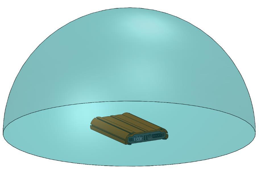
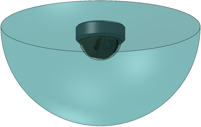
12 Geometry Geometry Mesh Materials Conditions Solution Results Air: Natural Convection To simulate air flow & heat transfer on the exterior, model the surrounding air (use a sphere as the baseline, diameter ~3-5X the bounding box diagonal). To model the heat transfer on the exterior, add boundary conditions (e.g. heat transfer coefficient)

13 Geometry Geometry Mesh Materials Conditions Solution Results
14 Mesh Geometry Mesh Materials Results Solution Conditions
15 Mesh Geometry Mesh Materials Conditions Solution Results Cell topology Polyhedral Conformal Non-conformal Trimmed hexahedral Non-conformal Approaches Parts-based Regions-based Specialty options Prism-layer mesher Thin mesher Extruded mesher Basic setting: Mesh sizing Conformal vs Non-conformal Conformal possible only with polyhedral cells Non-conformal an option with polyhedral, trimmed hexahedral Accuracy Fully conformal is best (no interpolation at interfaces) Non-conformal with similar surface mesh sizes: Tests show very small (<0.5%) difference than fully-conformal results. Non-conformal with disparate mesh sizes: Accuracy degrades as surface size variance increases Meshing speed Non-conformal is fastest Serial & parallel option for both Concurrent option for non-conf
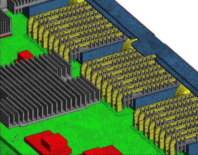
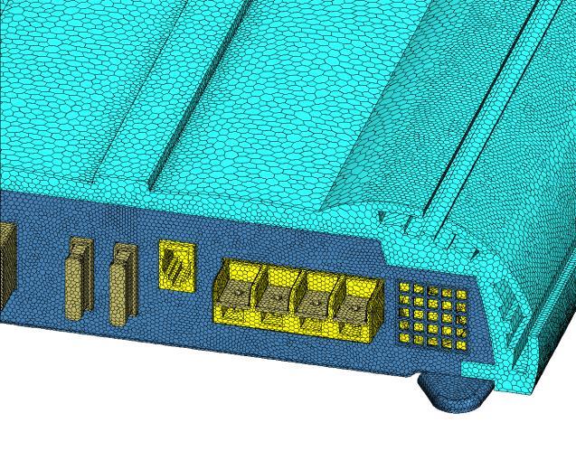
16 Mesh Geometry Mesh Materials Conditions Solution Results Parts-based vs Regions-based Personal preference Parts-based has advantages for complex mesh sequences New thin mesher in PBM Thin mesher (for solids) 1-2 layers for conducting-only solids (no heat dissipation) 3+ layers for thin solids that dissipate heat Methodology Surface mesh all geometry in 1- step (e.g. 1 PBM operation) Base size: 2-5% of bounding box diagonal Min surface size: % of base Curvature: 16 points / circle Proximity: 0.25 points in gap Produces conformal surface mesh Volume mesh Conformal or non-conformal Poly or trimmed hex or mixed Conformal polyhedral recommended for S2S radiation 2-4 prism layers at all fluid walls (e.g. fluid-solid interfaces, exterior fluid boundaries)


17 Mesh Geometry Mesh Materials Conditions Solution Results Fluid prism layers Nonconformal fluid-solid interface Conformal solid-solid interface

18 Mesh Geometry Mesh Materials Conditions Solution Results
19 Materials Geometry Mesh Materials Results Solution Conditions
20 Materials Geometry Mesh Materials Conditions Solution Results Solids Air (fluid) Devices Chips PCBs Porous media, perforated plates Heat pipes Thermoelectric devices Most material specifications are detailed in the corresponding continua Pick from the default library Customize, save to library Some require details in the corresponding region Solids Isotropic properties by default Thermal conductivity can be anisotropic set Method of Thermal Conductivity in continua Set values in appropriate region No temperature variation by default Change in the continua Specific heat: Polynomial in T Thermal conductivity: Polynomial in T, table(t), field function

, pg.")
21 Materials Geometry Mesh Materials Conditions Solution Results Source: Incropera & De Witt, Fundamentals of Heat and Mass Transfer, Third Edition (New York: John Wiley & Sons, 1990), pg. A15.
22 Materials Geometry Mesh Materials Conditions Solution Results Fluid Most commonly air Liquid cooling with water, ethylene-glycol solution, etc. Properties & appropriate physics specified in the continua Properties Density Viscosity Specific heat Thermal conductivity Physics Laminar or turbulent Turbulence model Properties: Air Density For buoyancy (natural convection), density must vary with temperature (+ gravity) Ambient pressure strongly affects air density (e.g. at altitude) Viscosity can significantly vary with temperature Properties: Water Density Variation with temperature important only with natural convection (rare cases) Little variation with pressure Viscosity variation with temperature can be significant


23 Materials Geometry Mesh Materials Conditions Solution Results Common temperature range in electronics


24 Materials Geometry Mesh Materials Conditions Solution Results


25 Materials Geometry Mesh Materials Conditions Solution Results
26 Materials Geometry Mesh Materials Conditions Solution Results Laminar or Turbulent (for air) Forced convection: Generally turbulent Internal: Re ~ ,000 External: Re ~ 500,000 Natural convection: Generally laminar Turbulent if Ra h > 10 9 (vertical flat plate) Ra h = gβ T w T h 3 υα Assume T w = 85 o C T = 50 o C 70 o C h critical = 0.83 m Turbulence model Many options in STAR-CCM+, consult the help for details k-ε k-ω Reynolds stress Spalart-Allmaras DES LES Realizable k-ε with two-layer ally+ wall treatment seems to work well for a wide range of models Forced convection Natural convection Compared a laminar run with a k-ε run Essentially identical flow & thermal results

 Separate boundaries (in the region) for top & bottom surfaces Assign resistivity to")

27 Materials Geometry Mesh Materials Conditions Solution Results Device: Chips Solid (isotropic) material 2-resistor High conductivity solid (e.g. Cu) Separate boundaries (in the region) for top & bottom surfaces Assign resistivity to interfaces to achieve ϴ jb & ϴ jc. Resistivity ρ = t / k = R t *A contact. Device: PCBs Equivalent thermal properties Orthotropic equivalent properties computed from geometric details (easiest in a spreadsheet) Commonly k in-plane ~ 10 W/m-K ~ 20*k through-thickness. Detailed trace modeling Computationally costly 2D or 3D traces
 Inertial: ΔP α V 2 (e.")
 Wick (k = 30-40 W/m-K) Vapor space (k > 10,000 W/m-K)")
28 Materials Geometry Mesh Materials Conditions Solution Results Device: Porous media Fluid region, Type = Porous Region Set Inertial &/or Viscous resistance values under Region Physics Values Viscous: ΔP α V (e.g. fibrous filter) Inertial: ΔP α V 2 (e.g. perf plate) Device: Heat pipes Rarely are the full physics (evaporation, condensation, surface tension, etc.) modeled. Typically 3-part assembly Pipe wall (k = material conductivity) Wick (k = W/m-K) Vapor space (k > 10,000 W/m-K)
.")

29 Materials Geometry Mesh Materials Conditions Solution Results Device: Thermoelectric devices Extract parameters from datasheet values (T c, Q max, T max, R electrical ). 3-part assembly (don t mesh the middle part) Field functions to iteratively compute & apply Q c (T c, T h ) & Q h (T c, T h ). Device: Contact resistance Every solid-solid interface physically has contact resistance. Default in STAR-CCM+ is R c = 0. To change, assign resistivity (ρ c ) to the interface (in Physics Values) ρ c = R c *A contact.


30 Conditions Geometry Mesh Materials Results Solution Conditions
31 Conditions Geometry Mesh Materials Conditions Solution Results Physics Air flow Heat transfer Conduction Convection Radiation Environment Inlet(s) Outlet(s) Thermal (including radiation) Heat sources Fans & blowers Air- (or water- or ) flow Computed if you have a fluid region Navier-Stokes equations Heat transfer Conduction computed in all regions (solids & fluids) Convection computed anywhere a fluid & solid touch (interface) Radiation needs to be activated In fluid region In transparent solid regions Methods Surface-to-surface (S2S) Discrete Ordinate Method (DOM) Solar radiation Available with S2S More later
32 Conditions Geometry Mesh Materials Conditions Solution Results What are you trying to determine? What is the goal of the simulation? Are you simulating a test or usage? What do you know about the conditions? Which variables are controlled? What are the unknowns you are trying to measure? Fluid (momentum) Heat (thermal energy) Flow driver Inlet(s) Outlet(s) Where does air enter & exit? What causes the air to flow? Fan (on boundary or internal) Pressure differential Supplied flow rate Buoyancy Stagnation inlet (Positive) Velocity, mass flow, or pressure Pressure outlet (Negative) Velocity, mass flow, or pressure Where does heat enter & exit the system? What is dissipating heat? What are the thermal paths through the model? Ambient temperature Heat generation (volumetric, surface) Ambient temperature Convection on exterior surfaces (h = 5 10 W/m 2 -K) no exterior air
33 Conditions Geometry Mesh Materials Conditions Solution Results Radiation: Base setup Continua: Activate radiation for air continua & any transparent solids. Regions > Boundaries Air: Set ε on the interface boundaries (ρ is computed) Transparent solids: Set ε on the interface boundaries that interface with the air (ρ is computed) Interfaces Set τ values only for interfaces between air & transparent solids. Radiation exchange with the environment (exterior) Set conditions on exterior air boundary (ε & τ, ρ is computed) Exterior environment ( outside the computational domain) is treated as a blackbody Radiation temperature is set in the continua (under Models > Thermal Radiation > Thermal Environments) Solar radiation Activate Solar Loads in continua (with radiation already activated) Set factors (e.g. date, time, location, orientation) in Models > Solar Loads for the continua
 ε = 0.")
34 Conditions Geometry Mesh Materials Conditions Solution Results No radiation ε = 0.3 (T max -12%) ε = 0.8 (T max -26%)
35 Conditions Geometry Mesh Materials Conditions Solution Results How do we know the heat dissipation to specify for a component? Electrical power supplied Wall power? Max power (power budget)? Measured power? Duty-cycled? What is the efficiency? Component (e.g. IC, IGBT, MOSFET, LED, ) Electrical power delivered Heat RF energy, visible light Apply the heat dissipation to the appropriate region Activate the Energy Source Option in Physics Conditions Assign the Heat Source in Physics Values Value assigned applies to the entire region (even if it consists of multiple parts).


36 Conditions Geometry Mesh Materials Conditions Solution Results Fan Curve dp Q Fan Model Steady (MRF) Unsteady Fan Simulation Options No CAD needed Fewer cells Short runtime Less accurate CAD needed More cells Moderate runtime More accurate CAD needed More cells Long runtime Most accurate

37 Conditions Geometry Mesh Materials Conditions Solution Results Fan models in STAR-CCM+ (immersed fans) Volume momentum source Interface momentum source Recommendation: Interface Geometry with faces where the interface is desired. Set interface Type = Fan Interface. Input the desired fan curve Boundary fans (inlet and/or outlet) also available STAR-CCM+ iterates to find the flow rate / pressure drop combination at the intersection of the fan curve & the system resistance curve. Blowers are modeled as a special interface type Centrifugal fan Impeller fan
38 Solution Geometry Mesh Materials Results Solution Conditions
39 Solution Geometry Mesh Materials Conditions Solution Results Continua settings Physics models Reference values Initial conditions Solution settings Under-relaxation Convergence Solids continua Models Segregated Solid Energy Reference values None Initial conditions Static temperature = T ambient Air continuum Models Segregated Fluid Temperature Ideal gas or Boussinesq recommended for natural convection Gravity (activated) Reference values Gravity (vector direction) for natural convection Reference altitude Reference density = density at T ambient (based on ideal gas) Initial conditions Pressure = 0 (gage) Static temperature = T ambient Velocity = 0

 Effect: Convergence in fewer iterations (~5X fewer)")
40 Solution Geometry Mesh Materials Conditions Solution Results Fluid energy: Change to 0.99 (default = 0.9) Solid energy: Change to (default = 0.99) Effect: Convergence in fewer iterations (~5X fewer) Stable, even with radiation
41 Results Geometry Mesh Materials Results Solution Conditions


42 Results Geometry Mesh Materials Conditions Solution Results


43 Results Geometry Mesh Materials Conditions Solution Results STAR-View+
44 Thank you! Ruben Bons / ruben.bons@cd-adapco.com /
Isotropic Porous Media Tutorial
 STAR-CCM+ User Guide 3927 Isotropic Porous Media Tutorial This tutorial models flow through the catalyst geometry described in the introductory section. In the porous region, the theoretical pressure drop
Free Convection Cookbook for StarCCM+
 ME 448/548 February 28, 2012 Free Convection Cookbook for StarCCM+ Gerald Recktenwald gerry@me.pdx.edu 1 Overview Figure 1 depicts a two-dimensional fluid domain bounded by a cylinder of diameter D. Inside
STAR-CCM+: Wind loading on buildings SPRING 2018
 STAR-CCM+: Wind loading on buildings SPRING 2018 1. Notes on the software 2. Assigned exercise (submission via Blackboard; deadline: Thursday Week 3, 11 pm) 1. NOTES ON THE SOFTWARE STAR-CCM+ generates
COOL-COVERINGS. André Santos, The Netherlands Copyright Active Space Technologies
 COOL-COVERINGS André Santos, The Netherlands 21-03-2012 Copyright Active Space Technologies 2004-2011 Young and competent company Started in 2007 in Germany, in 2004 in Portugal Role Support scientific
Simulation of Flow Development in a Pipe
 Tutorial 4. Simulation of Flow Development in a Pipe Introduction The purpose of this tutorial is to illustrate the setup and solution of a 3D turbulent fluid flow in a pipe. The pipe networks are common
Axial Channel Water Jacket Cooling
 28 November 2017 Motor-CAD Software Tutorial: Axial Channel Water Jacket Cooling Contents 1. Description... 1 2. Setting up the housing and axial channels... 2 3. Setting the water jacket fluid and flow
STAR Global Conference 2012 Noordwijk, March 20-21, The InDesA Virtual Test Bench. Dr. Fabiano Bet Dr. Gerald Seider
 STAR Global Conference 2012 Noordwijk, March 20-21, 2012 The InDesA Dr. Fabiano Bet Dr. Gerald Seider Company Profile Consulting- & Engineering Services Simulation and Analysis of complex fluid flow and
Coupled Simulation of the Fluid Flow and Conjugate Heat Transfer in Press Hardening Processes
 13 th International LS-DYNA Users Conference Session: Metal Forming Coupled Simulation of the Fluid Flow and Conjugate Heat Transfer in Press Hardening Processes Uli Göhner 1), Bruno Boll 1), Inaki Caldichouri
COMPUTATIONAL FLUID DYNAMICS ANALYSIS OF ORIFICE PLATE METERING SITUATIONS UNDER ABNORMAL CONFIGURATIONS
 COMPUTATIONAL FLUID DYNAMICS ANALYSIS OF ORIFICE PLATE METERING SITUATIONS UNDER ABNORMAL CONFIGURATIONS Dr W. Malalasekera Version 3.0 August 2013 1 COMPUTATIONAL FLUID DYNAMICS ANALYSIS OF ORIFICE PLATE
Accurate and Efficient Turbomachinery Simulation. Chad Custer, PhD Turbomachinery Technical Specialist
 Accurate and Efficient Turbomachinery Simulation Chad Custer, PhD Turbomachinery Technical Specialist Outline Turbomachinery simulation advantages Axial fan optimization Description of design objectives
Optimization of under-relaxation factors. and Courant numbers for the simulation of. sloshing in the oil pan of an automobile
 Optimization of under-relaxation factors and Courant numbers for the simulation of sloshing in the oil pan of an automobile Swathi Satish*, Mani Prithiviraj and Sridhar Hari⁰ *National Institute of Technology,
Calculate a solution using the pressure-based coupled solver.
 Tutorial 19. Modeling Cavitation Introduction This tutorial examines the pressure-driven cavitating flow of water through a sharpedged orifice. This is a typical configuration in fuel injectors, and brings
STAR-CCM+: Ventilation SPRING Notes on the software 2. Assigned exercise (submission via Blackboard; deadline: Thursday Week 9, 11 pm)
") STAR-CCM+: Ventilation SPRING 208. Notes on the software 2. Assigned exercise (submission via Blackboard; deadline: Thursday Week 9, pm). Features of the Exercise Natural ventilation driven by localised
STAR-CCM+: Ventilation SPRING 208. Notes on the software 2. Assigned exercise (submission via Blackboard; deadline: Thursday Week 9, pm). Features of the Exercise Natural ventilation driven by localised
Pressure Losses Analysis in Air Duct Flow Using Computational Fluid Dynamics (CFD)
") International Academic Institute for Science and Technology International Academic Journal of Science and Engineering Vol. 3, No. 9, 2016, pp. 55-70. ISSN 2454-3896 International Academic Journal of Science
International Academic Institute for Science and Technology International Academic Journal of Science and Engineering Vol. 3, No. 9, 2016, pp. 55-70. ISSN 2454-3896 International Academic Journal of Science
Coupled Analysis of FSI
 Coupled Analysis of FSI Qin Yin Fan Oct. 11, 2008 Important Key Words Fluid Structure Interface = FSI Computational Fluid Dynamics = CFD Pressure Displacement Analysis = PDA Thermal Stress Analysis = TSA
CFD in COMSOL Multiphysics
 CFD in COMSOL Multiphysics Christian Wollblad Copyright 2017 COMSOL. Any of the images, text, and equations here may be copied and modified for your own internal use. All trademarks are the property of
PRESSURE DROP AND FLOW UNIFORMITY ANALYSIS OF COMPLETE EXHAUST SYSTEMS FOR DIESEL ENGINES
 PRESSURE DROP AND FLOW UNIFORMITY ANALYSIS OF COMPLETE EXHAUST SYSTEMS FOR DIESEL ENGINES André Bergel 1 Edson L. Duque 2 General Motors Global Propulsion Systems South America 12 E-mail: andrebergel84@yahoo.com.br
McNair Scholars Research Journal
 McNair Scholars Research Journal Volume 2 Article 1 2015 Benchmarking of Computational Models against Experimental Data for Velocity Profile Effects on CFD Analysis of Adiabatic Film-Cooling Effectiveness
First Steps - Conjugate Heat Transfer
 COSMOSFloWorks 2004 Tutorial 2 First Steps - Conjugate Heat Transfer This First Steps - Conjugate Heat Transfer tutorial covers the basic steps to set up a flow analysis problem including conduction heat
Best Practices: Volume Meshing Kynan Maley
 Best Practices: Volume Meshing Kynan Maley Volume Meshing Volume meshing is the basic tool that allows the creation of the space discretization needed to solve most of the CAE equations for: CFD Stress
Recent & Upcoming Features in STAR-CCM+ for Aerospace Applications Deryl Snyder, Ph.D.
 Recent & Upcoming Features in STAR-CCM+ for Aerospace Applications Deryl Snyder, Ph.D. Outline Introduction Aerospace Applications Summary New Capabilities for Aerospace Continuity Convergence Accelerator
Impact of STAR-CCM+ v7.0 in the Automotive Industry Frederick J. Ross, CD-adapco Director, Ground Transportation
 Impact of STAR-CCM+ v7.0 in the Automotive Industry Frederick J. Ross, CD-adapco Director, Ground Transportation Vehicle Simulation Components Vehicle Aerodynamics Design Studies Aeroacoustics Water/Dirt
Tutorial 1. Introduction to Using FLUENT: Fluid Flow and Heat Transfer in a Mixing Elbow
 Tutorial 1. Introduction to Using FLUENT: Fluid Flow and Heat Transfer in a Mixing Elbow Introduction This tutorial illustrates the setup and solution of the two-dimensional turbulent fluid flow and heat
CFD VALIDATION FOR SURFACE COMBATANT 5415 STRAIGHT AHEAD AND STATIC DRIFT 20 DEGREE CONDITIONS USING STAR CCM+
 CFD VALIDATION FOR SURFACE COMBATANT 5415 STRAIGHT AHEAD AND STATIC DRIFT 20 DEGREE CONDITIONS USING STAR CCM+ by G. J. Grigoropoulos and I..S. Kefallinou 1. Introduction and setup 1. 1 Introduction The
Tutorial 2. Modeling Periodic Flow and Heat Transfer
 Tutorial 2. Modeling Periodic Flow and Heat Transfer Introduction: Many industrial applications, such as steam generation in a boiler or air cooling in the coil of an air conditioner, can be modeled as
Transition Flow and Aeroacoustic Analysis of NACA0018 Satish Kumar B, Fred Mendonç a, Ghuiyeon Kim, Hogeon Kim
 Transition Flow and Aeroacoustic Analysis of NACA0018 Satish Kumar B, Fred Mendonç a, Ghuiyeon Kim, Hogeon Kim Transition Flow and Aeroacoustic Analysis of NACA0018 Satish Kumar B, Fred Mendonç a, Ghuiyeon
ISSN(PRINT): ,(ONLINE): ,VOLUME-1,ISSUE-1,
: ,(ONLINE): ,VOLUME-1,ISSUE-1,") NUMERICAL ANALYSIS OF THE TUBE BANK PRESSURE DROP OF A SHELL AND TUBE HEAT EXCHANGER Kartik Ajugia, Kunal Bhavsar Lecturer, Mechanical Department, SJCET Mumbai University, Maharashtra Assistant Professor,
NUMERICAL ANALYSIS OF THE TUBE BANK PRESSURE DROP OF A SHELL AND TUBE HEAT EXCHANGER Kartik Ajugia, Kunal Bhavsar Lecturer, Mechanical Department, SJCET Mumbai University, Maharashtra Assistant Professor,
NUMERICAL INVESTIGATION OF THE FLOW BEHAVIOR INTO THE INLET GUIDE VANE SYSTEM (IGV)
") University of West Bohemia» Department of Power System Engineering NUMERICAL INVESTIGATION OF THE FLOW BEHAVIOR INTO THE INLET GUIDE VANE SYSTEM (IGV) Publication was supported by project: Budování excelentního
University of West Bohemia» Department of Power System Engineering NUMERICAL INVESTIGATION OF THE FLOW BEHAVIOR INTO THE INLET GUIDE VANE SYSTEM (IGV) Publication was supported by project: Budování excelentního
This tutorial illustrates how to set up and solve a problem involving solidification. This tutorial will demonstrate how to do the following:
 Tutorial 22. Modeling Solidification Introduction This tutorial illustrates how to set up and solve a problem involving solidification. This tutorial will demonstrate how to do the following: Define a
International Power, Electronics and Materials Engineering Conference (IPEMEC 2015)
") International Power, Electronics and Materials Engineering Conference (IPEMEC 2015) Numerical Simulation of the Influence of Intake Grille Shape on the Aerodynamic Performance of a Passenger Car Longwei
International Power, Electronics and Materials Engineering Conference (IPEMEC 2015) Numerical Simulation of the Influence of Intake Grille Shape on the Aerodynamic Performance of a Passenger Car Longwei
µ = Pa s m 3 The Reynolds number based on hydraulic diameter, D h = 2W h/(w + h) = 3.2 mm for the main inlet duct is = 359
 = 3.2 mm for the main inlet duct is = 359") Laminar Mixer Tutorial for STAR-CCM+ ME 448/548 March 30, 2014 Gerald Recktenwald gerry@pdx.edu 1 Overview Imagine that you are part of a team developing a medical diagnostic device. The device has a millimeter
Laminar Mixer Tutorial for STAR-CCM+ ME 448/548 March 30, 2014 Gerald Recktenwald gerry@pdx.edu 1 Overview Imagine that you are part of a team developing a medical diagnostic device. The device has a millimeter
CFD simulation of a simplified model of the Sardinia Radio Telescope
 CFD simulation of a simplified model of the Sardinia Radio Telescope Stage Activities Report CRS4 July October 2017 Author G. Murtas Coordinators Vincent Moreau, Manuela Profir LIST OF CONTENT LIST OF
CFD Simulation of Air Flow and Thermal Behavior of Electronics Assembly within Plastic Enclosure for Outdoor Environments
 Keywords: CFD Simulation, Computational Fluid Dynamics, CFD conjugate heat transfer, CFD natural convection, CFD PCB simulation, CFD electronics enclosures, CFD ASICS, thermal predictions of electronic
Directions: 1) Delete this text box 2) Insert desired picture here
 Delete this text box 2) Insert desired picture here") Directions: 1) Delete this text box 2) Insert desired picture here Multi-Disciplinary Applications using Overset Grid Technology in STAR-CCM+ CD-adapco Dmitry Pinaev, Frank Schäfer, Eberhard Schreck Outline
Directions: 1) Delete this text box 2) Insert desired picture here Multi-Disciplinary Applications using Overset Grid Technology in STAR-CCM+ CD-adapco Dmitry Pinaev, Frank Schäfer, Eberhard Schreck Outline
Using the Discrete Ordinates Radiation Model
 Tutorial 6. Using the Discrete Ordinates Radiation Model Introduction This tutorial illustrates the set up and solution of flow and thermal modelling of a headlamp. The discrete ordinates (DO) radiation
Vehicle thermal safety with THESEUS-FE. Author: Dr. Daniel Koester
 Author: Dr. Daniel Koester Date: September 4, 2014 Workflow for Underhood Simulations ANSA or other CAD/meshing software CAD cleanup and meshing: either CAD geometry description or NASTRAN-style FE meshes
SOLIDWORKS SIMULATION
 SOLIDWORKS SIMULATION Innovation is about taking chances, not taking risks Scootchi by Curventa Designworks LTD What if? is the question that fuels innovation. SolidWorks Simulation software takes the
Beat the Heat in Notebooks with Software
 Beat the Heat in Notebooks with Software Computational fluid dynamics software can help you solve system-level thermal packaging problems. Pentium-class portables present significant packaging problems.
Modeling Flow Through Porous Media
 Tutorial 7. Modeling Flow Through Porous Media Introduction Many industrial applications involve the modeling of flow through porous media, such as filters, catalyst beds, and packing. This tutorial illustrates
Advanced Applications of STAR- CCM+ in Chemical Process Industry Ravindra Aglave Director, Chemical Process Industry
 Advanced Applications of STAR- CCM+ in Chemical Process Industry Ravindra Aglave Director, Chemical Process Industry Outline Notable features released in 2013 Gas Liquid Flows with STAR-CCM+ Packed Bed
Thermal Management of Electronics in Drilling and Completion. Gokul V Shankaran
 Thermal Management of Electronics in Drilling and Completion Gokul V Shankaran 1 Background Electronics circuitry in down hole tools to collect sensors data, drive actuators, multiplexing, data storage
A B C D E. Settings Choose height, H, free stream velocity, U, and fluid (dynamic viscosity and density ) so that: Reynolds number
 so that: Reynolds number") Individual task Objective To derive the drag coefficient for a 2D object, defined as where D (N/m) is the aerodynamic drag force (per unit length in the third direction) acting on the object. The object
Individual task Objective To derive the drag coefficient for a 2D object, defined as where D (N/m) is the aerodynamic drag force (per unit length in the third direction) acting on the object. The object
Computational Fluid Dynamics (CFD) Simulation in Air Duct Channels Using STAR CCM+
 Simulation in Air Duct Channels Using STAR CCM+") Available onlinewww.ejaet.com European Journal of Advances in Engineering and Technology, 2017,4 (3): 216-220 Research Article ISSN: 2394-658X Computational Fluid Dynamics (CFD) Simulation in Air Duct
Available onlinewww.ejaet.com European Journal of Advances in Engineering and Technology, 2017,4 (3): 216-220 Research Article ISSN: 2394-658X Computational Fluid Dynamics (CFD) Simulation in Air Duct
Introduction to CFX. Workshop 2. Transonic Flow Over a NACA 0012 Airfoil. WS2-1. ANSYS, Inc. Proprietary 2009 ANSYS, Inc. All rights reserved.
 Workshop 2 Transonic Flow Over a NACA 0012 Airfoil. Introduction to CFX WS2-1 Goals The purpose of this tutorial is to introduce the user to modelling flow in high speed external aerodynamic applications.
Femap Thermal & Flow V11
 Femap Thermal & Flow V11 by Carl J. Poplawsky presented to Femap Symposium Ann Arbor, MI. date June 4th, 2015 MAYA Company Overview OEM Foundation Siemens PLM Partner 30+ years Software Developer Femap
Solver Basics. Introductory FLUENT Training ANSYS, Inc. All rights reserved. ANSYS, Inc. Proprietary
 Solver Basics Introductory FLUENT Training 2006 ANSYS, Inc. All rights reserved. 2006 ANSYS, Inc. All rights reserved. 3-2 Solver Execution The menus are arranged such that the order of operation is generally
CDA Workshop Physical & Numerical Hydraulic Modelling. STAR-CCM+ Presentation
 CDA Workshop Physical & Numerical Hydraulic Modelling STAR-CCM+ Presentation ENGINEERING SIMULATION CFD FEA Mission Increase the competitiveness of companies through optimization of their product development
CIBSE Application Manual AM11 Building Performance Modelling Chapter 6: Ventilation Modelling
 Contents Background Ventilation modelling tool categories Simple tools and estimation techniques Analytical methods Zonal network methods Computational Fluid Dynamics (CFD) Semi-external spaces Summary
Optimizing Bio-Inspired Flow Channel Design on Bipolar Plates of PEM Fuel Cells
 Excerpt from the Proceedings of the COMSOL Conference 2010 Boston Optimizing Bio-Inspired Flow Channel Design on Bipolar Plates of PEM Fuel Cells James A. Peitzmeier *1, Steven Kapturowski 2 and Xia Wang
Best Practices Workshop: Parts & Mesh-Based Operations
 Best Practices Workshop: Parts & Mesh-Based Operations Overview What are Parts and Mesh Based Operations? Transition from Region Based Meshing Why move to Parts Based Meshing How to use Parts Based Mesh
Solid Conduction Tutorial
 SECTION 1 1 SECTION 1 The following is a list of files that will be needed for this tutorial. They can be found in the Solid_Conduction folder. Exhaust-hanger.tdf Exhaust-hanger.ntl 1.0.1 Overview The
equivalent stress to the yield stess.
 Example 10.2-1 [Ansys Workbench/Thermal Stress and User Defined Result] A 50m long deck sitting on superstructures that sit on top of substructures is modeled by a box shape of size 20 x 5 x 50 m 3. It
SIMULATION OF FLOW AROUND KCS-HULL
 SIMULATION OF FLOW AROUND KCS-HULL Sven Enger (CD-adapco, Germany) Milovan Perić (CD-adapco, Germany) Robinson Perić (University of Erlangen-Nürnberg, Germany) 1.SUMMARY The paper describes results of
A new meshing methodology for faster simulation of a Body-In-White dipping process
 A new meshing methodology for faster simulation of a Body-In-White dipping process Madhusudhan Devanathan MBtech Group GmbH & Co. KGaA, Sindelfingen, Germany STAR Global Conference 19 1 March 01, Amsterdam
Lab 9: FLUENT: Transient Natural Convection Between Concentric Cylinders
 Lab 9: FLUENT: Transient Natural Convection Between Concentric Cylinders Objective: The objective of this laboratory is to introduce how to use FLUENT to solve both transient and natural convection problems.
Streamlining Aircraft Icing Simulations. D. Snyder, M. Elmore
 Streamlining Aircraft Icing Simulations D. Snyder, M. Elmore Industry Analysis Needs / Trends Fidelity Aircraft Ice Protection Systems-Level Modeling Optimization Background Ice accretion can critically
Offshore Platform Fluid Structure Interaction (FSI) Simulation
 Simulation") Offshore Platform Fluid Structure Interaction (FSI) Simulation Ali Marzaban, CD-adapco Murthy Lakshmiraju, CD-adapco Nigel Richardson, CD-adapco Mike Henneke, CD-adapco Guangyu Wu, Chevron Pedro M. Vargas,
Offshore Platform Fluid Structure Interaction (FSI) Simulation Ali Marzaban, CD-adapco Murthy Lakshmiraju, CD-adapco Nigel Richardson, CD-adapco Mike Henneke, CD-adapco Guangyu Wu, Chevron Pedro M. Vargas,
Temperature Analysis of Intel Server by using CFD and Experimentation
 Temperature Analysis of Intel Server by using CFD and Experimentation Chetan A Gawande 1, Prof. S.M. Nakate 2, Prasad Chavan 3 ¹Dept. of Mechanical engineering, MIT Pune, Pune University, pune India ²Dept.
Modeling Evaporating Liquid Spray
 Tutorial 16. Modeling Evaporating Liquid Spray Introduction In this tutorial, FLUENT s air-blast atomizer model is used to predict the behavior of an evaporating methanol spray. Initially, the air flow
Tutorial: Heat and Mass Transfer with the Mixture Model
 Tutorial: Heat and Mass Transfer with the Mixture Model Purpose The purpose of this tutorial is to demonstrate the use of mixture model in FLUENT 6.0 to solve a mixture multiphase problem involving heat
Coupling of STAR-CCM+ to Other Theoretical or Numerical Solutions. Milovan Perić
 Coupling of STAR-CCM+ to Other Theoretical or Numerical Solutions Milovan Perić Contents The need to couple STAR-CCM+ with other theoretical or numerical solutions Coupling approaches: surface and volume
Advances in Cyclonic Flow Regimes. Dr. Dimitrios Papoulias, Thomas Eppinger
 Advances in Cyclonic Flow Regimes Dr. Dimitrios Papoulias, Thomas Eppinger Agenda Introduction Cyclones & Hydrocyclones Modeling Approaches in STAR-CCM+ Turbulence Modeling Case 1: Air-Air Cyclone Case
ANSYS AIM Tutorial Turbulent Flow Over a Backward Facing Step
 ANSYS AIM Tutorial Turbulent Flow Over a Backward Facing Step Author(s): Sebastian Vecchi, ANSYS Created using ANSYS AIM 18.1 Problem Specification Pre-Analysis & Start Up Governing Equation Start-Up Geometry
Reproducibility of Complex Turbulent Flow Using Commercially-Available CFD Software
 Reports of Research Institute for Applied Mechanics, Kyushu University No.150 (71 83) March 2016 Reproducibility of Complex Turbulent Flow Using Commercially-Available CFD Software Report 3: For the Case
Verification and Validation in CFD and Heat Transfer: ANSYS Practice and the New ASME Standard
 Verification and Validation in CFD and Heat Transfer: ANSYS Practice and the New ASME Standard Dimitri P. Tselepidakis & Lewis Collins ASME 2012 Verification and Validation Symposium May 3 rd, 2012 1 Outline
Adjoint Solver Workshop
 Adjoint Solver Workshop Why is an Adjoint Solver useful? Design and manufacture for better performance: e.g. airfoil, combustor, rotor blade, ducts, body shape, etc. by optimising a certain characteristic
FLOWVISION CFD FREQUENTLY ASKED QUESTIONS
 FLOWVISION CFD FREQUENTLY ASKED QUESTIONS 1. Installation and Licensing 1.1. Does FlowVision have floating licenses? 1.1.1. Actually all FlowVision licenses have floating capability and no extra fees are
INVESTIGATION OF HYDRAULIC PERFORMANCE OF A FLAP TYPE CHECK VALVE USING CFD AND EXPERIMENTAL TECHNIQUE
 International Journal of Mechanical Engineering and Technology (IJMET) Volume 10, Issue 1, January 2019, pp. 409 413, Article ID: IJMET_10_01_042 Available online at http://www.ia aeme.com/ijmet/issues.asp?jtype=ijmet&vtype=
THERMAL OPTIMIZATION OF GENSET CANOPY USING CFD
 International Journal of Mechanical and Production Engineering Research and Development (IJMPERD) ISSN(P): 2249-6890; ISSN(E): 2249-8001 Vol. 5, Issue 3, Jun 2015, 19-26 TJPRC Pvt. Ltd. THERMAL OPTIMIZATION
Study Of Overloading Effects, In A Refrigerated Display Case
 Study Of Overloading Effects, In A Refrigerated Display Case Sandeep Palaksha Senior CAE Engineer HUSSMANN Basavanagudi Bangalore 04, India p.sandeep@hussmann.com Narasimhamurthy CAE Engineer HUSSMANN
Navier-Stokes & Flow Simulation
 Last Time? Navier-Stokes & Flow Simulation Implicit Surfaces Marching Cubes/Tetras Collision Detection & Response Conservative Bounding Regions backtracking fixing Today Flow Simulations in Graphics Flow
Tutorial to simulate a thermoelectric module with heatsink in ANSYS
 Tutorial to simulate a thermoelectric module with heatsink in ANSYS Few details can be found in the pictures attached. All the material properties can be found in Dr. Lee s book and on the web. Don t blindly
Convection Cooling of Circuit Boards 3D Natural Convection
 Convection Cooling of Circuit Boards 3D Natural Convection Introduction This example models the air cooling of circuit boards populated with multiple integrated circuits (ICs), which act as heat sources.
SPC 307 Aerodynamics. Lecture 1. February 10, 2018
 SPC 307 Aerodynamics Lecture 1 February 10, 2018 Sep. 18, 2016 1 Course Materials drahmednagib.com 2 COURSE OUTLINE Introduction to Aerodynamics Review on the Fundamentals of Fluid Mechanics Euler and
CFD Modeling of a Radiator Axial Fan for Air Flow Distribution
 CFD Modeling of a Radiator Axial Fan for Air Flow Distribution S. Jain, and Y. Deshpande Abstract The fluid mechanics principle is used extensively in designing axial flow fans and their associated equipment.
Tutorial 17. Using the Mixture and Eulerian Multiphase Models
 Tutorial 17. Using the Mixture and Eulerian Multiphase Models Introduction: This tutorial examines the flow of water and air in a tee junction. First you will solve the problem using the less computationally-intensive
Industrial wind tunnel analysis based on current modeling and future outlook
 Industrial wind tunnel analysis based on current modeling and future outlook Rafael José Mateus Vicente Instituto Superior Técnico Abstract The purpose of this work is to study
Autodesk Moldflow Insight AMI Cool Analysis Products
 Autodesk Moldflow Insight 2012 AMI Cool Analysis Products Revision 1, 22 March 2012. This document contains Autodesk and third-party software license agreements/notices and/or additional terms and conditions
Modeling Evaporating Liquid Spray
 Tutorial 17. Modeling Evaporating Liquid Spray Introduction In this tutorial, the air-blast atomizer model in ANSYS FLUENT is used to predict the behavior of an evaporating methanol spray. Initially, the
STAR-CCM+ User Guide 6922
 STAR-CCM+ User Guide 6922 Introduction Welcome to the STAR-CCM+ introductory tutorial. In this tutorial, you explore the important concepts and workflow. Complete this tutorial before attempting any others.
CFD Optimisation case studies with STAR-CD and STAR-CCM+
 CFD Optimisation case studies with STAR-CD and STAR-CCM+ Summary David J. Eby, Preetham Rao, Advanced Methods Group, Plymouth, MI USA Presented by Fred Mendonça, CD-adapco London, UK Outline Introduction
1.2 Numerical Solutions of Flow Problems
 1.2 Numerical Solutions of Flow Problems DIFFERENTIAL EQUATIONS OF MOTION FOR A SIMPLIFIED FLOW PROBLEM Continuity equation for incompressible flow: 0 Momentum (Navier-Stokes) equations for a Newtonian
CFD design tool for industrial applications
 Sixth LACCEI International Latin American and Caribbean Conference for Engineering and Technology (LACCEI 2008) Partnering to Success: Engineering, Education, Research and Development June 4 June 6 2008,
Optimizing the Integration of an Electronics System into an Existing Enclosure Using CFD Modeling Techniques
 Optimizing the Integration of an Electronics System into an Existing Enclosure Using CFD Modeling Techniques Optimizing the Integration of an Electronics System into an Existing Enclosure Using CFD Modeling
Non-Newtonian Transitional Flow in an Eccentric Annulus
 Tutorial 8. Non-Newtonian Transitional Flow in an Eccentric Annulus Introduction The purpose of this tutorial is to illustrate the setup and solution of a 3D, turbulent flow of a non-newtonian fluid. Turbulent
Use of CFD in Design and Development of R404A Reciprocating Compressor
 Purdue University Purdue e-pubs International Compressor Engineering Conference School of Mechanical Engineering 2006 Use of CFD in Design and Development of R404A Reciprocating Compressor Yogesh V. Birari
Speed and Accuracy of CFD: Achieving Both Successfully ANSYS UK S.A.Silvester
 Speed and Accuracy of CFD: Achieving Both Successfully ANSYS UK S.A.Silvester 2010 ANSYS, Inc. All rights reserved. 1 ANSYS, Inc. Proprietary Content ANSYS CFD Introduction ANSYS, the company Simulation
Animation of Fluids. Animating Fluid is Hard
 Animation of Fluids Animating Fluid is Hard Too complex to animate by hand Surface is changing very quickly Lots of small details In short, a nightmare! Need automatic simulations AdHoc Methods Some simple
Introduction to ANSYS CFX
 Workshop 03 Fluid flow around the NACA0012 Airfoil 16.0 Release Introduction to ANSYS CFX 2015 ANSYS, Inc. March 13, 2015 1 Release 16.0 Workshop Description: The flow simulated is an external aerodynamics
First Steps - Ball Valve Design
 COSMOSFloWorks 2004 Tutorial 1 First Steps - Ball Valve Design This First Steps tutorial covers the flow of water through a ball valve assembly before and after some design changes. The objective is to
FloEFD 16 What s New. Alexey Kharitonovich Product Manager. Tatiana Trebunskikh Product Manager
 FloEFD 16 What s New Alexey Kharitonovich Product Manager Tatiana Trebunskikh Product Manager FloEFD 16 Enhancements Phase Change for Refrigerants Flows of refrigerants with liquid to gas (cavitation/boiling)
Ashwin Shridhar et al. Int. Journal of Engineering Research and Applications ISSN : , Vol. 5, Issue 6, ( Part - 5) June 2015, pp.
 June 2015, pp.") RESEARCH ARTICLE OPEN ACCESS Conjugate Heat transfer Analysis of helical fins with airfoil crosssection and its comparison with existing circular fin design for air cooled engines employing constant rectangular
RESEARCH ARTICLE OPEN ACCESS Conjugate Heat transfer Analysis of helical fins with airfoil crosssection and its comparison with existing circular fin design for air cooled engines employing constant rectangular
Preliminary Spray Cooling Simulations Using a Full-Cone Water Spray
 39th Dayton-Cincinnati Aerospace Sciences Symposium Preliminary Spray Cooling Simulations Using a Full-Cone Water Spray Murat Dinc Prof. Donald D. Gray (advisor), Prof. John M. Kuhlman, Nicholas L. Hillen,
Modeling and Simulation of Single Phase Fluid Flow and Heat Transfer in Packed Beds
 Modeling and Simulation of Single Phase Fluid Flow and Heat Transfer in Packed Beds by:- Balaaji Mahadevan Shaurya Sachdev Subhanshu Pareek Amol Deshpande Birla Institute of Technology and Science, Pilani
Middle East Technical University Mechanical Engineering Department ME 413 Introduction to Finite Element Analysis Spring 2015 (Dr.
 Middle East Technical University Mechanical Engineering Department ME 413 Introduction to Finite Element Analysis Spring 2015 (Dr. Sert) COMSOL 1 Tutorial 2 Problem Definition Hot combustion gases of a
Modeling External Compressible Flow
 Tutorial 3. Modeling External Compressible Flow Introduction The purpose of this tutorial is to compute the turbulent flow past a transonic airfoil at a nonzero angle of attack. You will use the Spalart-Allmaras
USING CFD SIMULATIONS TO IMPROVE THE MODELING OF WINDOW DISCHARGE COEFFICIENTS
 USING CFD SIMULATIONS TO IMPROVE THE MODELING OF WINDOW DISCHARGE COEFFICIENTS Erin L. Hult 1, Gianluca Iaccarino 2, and Martin Fischer 2 1 Lawrence Berkeley National Laboratory, Berkeley, CA 2 Stanford
Ben Zandi, Ph.D. TES International LLC
 Advances in Modeling and Simulation of Vehicle Thermal Management Systems Variable-Fidelity, Multi-System Analysis Ben Zandi, Ph.D. TES International LLC www.tesint.com Outline The Need for Vehicle Thermal
Air Movement. Air Movement
 2018 Air Movement In this tutorial you will create an air flow using a supply vent on one side of a room and an open vent on the opposite side. This is a very simple PyroSim/FDS simulation, but illustrates
Navier-Stokes & Flow Simulation
 Last Time? Navier-Stokes & Flow Simulation Optional Reading for Last Time: Spring-Mass Systems Numerical Integration (Euler, Midpoint, Runge-Kutta) Modeling string, hair, & cloth HW2: Cloth & Fluid Simulation