Holographic projection system with programmable control of state of polarization, focus plane and size of the reconstruction
|
|
|
- Dustin Randall
- 5 years ago
- Views:
Transcription
1 Holographic projection system with programmable control of state of polarization, focus plane and size of the reconstruction Jeffrey A. Davis, a Ignacio Moreno, b, Jason P. Sorger, a María M. Sánchez-López, c,* and Don M. Cottrell a a Department of Physics, San Diego State University, San Diego, California , USA b Departamento de Ciencia de Materiales, Óptica y Tecnología Electrónica, Universidad Miguel Hernández, Elche, Spain c Instituto de Bioingeniería, Departamento de Física y Arquitectura de Computadores, Universidad Miguel Hernández, Elche, Spain Abstract. A holographic projection system based on the encoding of computer-generated holograms onto a spatial light modulator is discussed. We show how the size, location, and polarization state of the output can be controlled completely electronically, without physically moving any element in the system. It is finally shown that the system is capable to produce optical logical operations by superimposing two different images encoded onto orthogonal polarization states. We show how these images can be added or subtracted, giving a polarization-based logic system. Experimental results are included in all cases. Keywords: Liquid-crystal displays, Computer-Generated Holograms, Polarization. *Corresponding Author, mar.sanchez@umh.es 1. Introduction As the resolution of spatial light modulators (SLMs) improves, the capability for encoding computergenerated holograms becomes more practical. Holographic laser projection [1] is one of the multiple applications that will benefit from the development of newer high resolution SLMs since they will provide higher quality image reconstruction. In this technique, a phase-only Fourier transform computer-generated hologram is computed and displayed onto a SLM. The hologram output reconstruction is recovered by optically Fourier transforming the field. A number of works have exploited this approach in combination with the use of three different wavelengths, to provide a large color range in comparison to conventional projectors [2-4]. 1
2 A requirement usually demanded in projection systems is the capability to focus the image in different planes and with different sizes. For that reason, holographic projector systems incorporate zoom lenses. These can be made with tunable lenses to provide automatic zoom and provide different magnifications without moving elements [5-7], or by using scaled Fresnel transforms as reported in [8]. Another important issue is the control of the state of polarization. For instance, in many 3D applications, the generation of images having different polarizations would be important when using special viewing glasses where each eye detects a different polarization state [9]. In this work, we discuss ways of encoding the Fourier transform of a desired output, the Fourier transform lens, and the output polarization state onto a single SLM. This way we are able to generate a holographic projection system where the state of polarization, and the focusing plane can be controlled at will from the computer, without any moving elements. The two key advances that allow us to achieve such type of control are: 1) an optical system that uses a double pass through a parallel aligned SLM to independently phase-modulate two orthogonal polarization components [10,11] and, 2) a Fourier transform algorithm useful for the fast calculation of diffraction patterns to be displayed onto SLMs [12]. Fresnel diffraction calculations have been applied to design precise computer-generated holograms to be displayed in SLMs [13]. We have previously used the fast calculation of Fresnel diffracted patterns to implement a virtual propagation system [14], where we could experimentally observe the propagation of a light beam without requiring any moving element. Here we extend this approach to achieve automatic control of the focusing plane of the holographic display system without requiring zoom lenses. Then we combine the polarization control to achieve a reconstruction image with controlled state of polarization. Finally, we show polarization-based logic operations based on the subtraction or addition of two polarization images. 2. Review of lens-encoded patterns 2
3 Let us begin with a brief review of computer-generated holograms. We use a one-dimensional notation for convenience and consider an input function g(x). Using a computer system, the inverse Fourier transform of this function can be formed as G(ξ) = F )* {g(x)}. (1) Here ξ denotes the spatial frequency. A phase-only function G(ξ) is desirable since it can be directly encoded by the display when the input polarization is linear and parallel to the LC director. However, G(ξ) in Eq. (1) is not in general a phase-only function. It is well-known that keeping only the phase of the Fourier transform of the image and discarding the magnitude results in an edge-enhancement effect [15]. Different techniques exist to avoid this effect. One simple method consists in multiplying the input object to be reconstructed by a random phase pattern [16]. Other techniques involve the use of iterative Fourier transform algorithms [17]. In these cases, the resulting function G(ξ) to be displayed onto the SLM is a phase-only function that reconstructs the desired pattern. However, note that, if required, amplitude and phase can be combined onto a single phase-only SLM using encoding techniques [18,19]. For simplicity, we assume here that G(ξ) is already a phase-only function that can be directly encoded onto the SLM. We achieve this situation simply by selecting input objects that already consist in edges, as it will be shown next in the experiments. There are two experimental ways of taking the Fourier transform of this function in order to obtain the original input function. One standard way is to place a converging external lens after the SLM. Assuming the lens is placed right behind the SLM and has a focal length F *, its corresponding quadratic phase function is represented as Z {ξ, F * } = exp{ iπξ 7 /λf * }. The Fourier transform of the function F{G(ξ)} = g(x) is formed in the focal plane of the lens. However, the size of the image is also controlled by the focal length F * of the lens. So, the size and location of the Fourier transform are determined by the external lens function. Note that ξ represents the spatial frequency of the function g(x). Thus, when G(ξ) is displayed onto an 3
4 SLM with N N pixels and a pixel size of Δ, the scale of the reconstruction is given proportional to λf * /NΔ. In the second and more versatile approach, the lens function can also be encoded onto the SLM. Here, the pattern encoded onto the SLM consists of the product of the inverse Fourier transform function with the converging lens function as [20]: H(ξ) = Z (ξ, F * )G(ξ) = Z (ξ, F * )F )* {g(x)}. (2) These are called Fourier lens encoded patterns. Note that the pixelated structure of the SLM imposes a limit to the shortest focal length that can be properly displayed in the SLM. This is known as the Nyquist focal length and it is given by F > = N 7 /λ [21], and a recent review of its implications in a zoom lens system was presented in [7]. As before, both the size and location of the output function are determined by the focal length F * of the lens. Therefore, if we change the output size, the location where the hologram reconstruction appears also changes. In a previous work [14], we were able to virtually move the focal plane by forming the Fresnel diffraction of the pattern in Eq. (2). As before, the size of the output will be determined by the focal length of the Fourier transform lens. However, now we can translate the location of the image by a distance d. To accomplish this, the angular spectrum method is applied [22]. In this algorithm, we take the Fourier transform of the function H(ξ) in Eq. (2). Next, we multiply this Fourier transform by a converging lens function whose focal length depends on the propagation distance d, by which we will translate the image location from the original focal point. Finally, we take the inverse Fourier transform of this product. This operation can be written (using the notation in Eq. (2)) as J(ξ) = F )* {Z (ξ, F 7 (d))f[h(ξ)]}. (3) 4
5 Here, the function Z (ξ, F 7 (d)) is a converging lens function whose focal length is given by F 7 = f 7 /d where f = NΔ 7 /λ is the Nyquist focal length for the Fourier transform performed by the computer, N is the array size, and Δ is the pixel size corresponding to the SLM. The function J(ξ) thus represents the pattern H(ξ) propagated a distance d from its original location. Therefore, when J(ξ) is displayed onto the SLM, which is kept fixed on in its original position, the result is equivalent to virtually placing the function H(ξ) a distance d from the SLM. Note that, in general, the function J(ξ) is not a phase-only function. However, as we show next, displaying only the phase of this function reproduced very well the expected result with the fully complex function. Therefore, in this case, the original output function that was formed at a distance F * from the SLM can be shifted to a new distance given by F * d, without physically moving any element in the system. The virtual location of the hologram has been displaced a distance d from the SLM. But the scale of the Fourier transform is kept fixed, determined by the value of F *. Thus, the flexibility of the proposed system includes changing the focal plane, while keeping constant the size of the hologram reconstruction. For computational purposes, this algorithm is much faster than the Fresnel diffraction algorithm because Eq. (3) involves two fast Fourier transform operations [12]. In this work, we present an additional advance of this capability where the polarization state of the output can be controlled. Next, we review our experimental system that allows such polarization control. 3. Generation of computer-generated holograms with designed polarization states In order to generate an output with a desired polarization state, we use our single SLM system that has been reported previously [10,11] and shown in Fig. 1. We use a transmissive parallel-aligned liquid crystal (LC) SLM manufactured by Seiko Epson with 640x480 pixels having dimensions of D=42 µm. The phase shift of each pixel is controlled over 2p radians at the Argon laser wavelength of nm. The LC director is 5
6 oriented vertically, and therefore the linear vertical polarization component is phase modulated, while the horizontal component is unaffected. The input to the system is selected linearly polarized oriented at 45 degrees to the LCSLM director axis. The LCSLM screen is divided in two halves, where two different phase patterns are addressed, each with a radius of N = 120 pixels, as shown in Fig. 1. The initial beam has vertical and horizontal polarization components A and B as shown in the figure. This beam illuminates the left half part of the screen where a first pattern G H (ξ), calculated following Eq. (1) is encoded. After the beam is transmitted, the output now consists of electric field components A and B where the desired pattern is encoded onto the vertical polarization component (A ). The horizontal component (B) is perpendicular to the LC director axis and is unaffected. Then, by means of a lens (L2) and a mirror (R), the beam is reflected back to the right part of the LCSLM. The initially vertical and horizontal linearly polarization components are reversed by the insertion of the quarter-wave plate (QWP), oriented at 45 degrees with respect to the LC director axis. Now the horizontal linear polarization component (B), which was not affected by the LCSLM in the initial passage, becomes vertically polarized on the beam illuminating the right side of the LCSLM and will be modulated by the second phase pattern G K (ξ) encoded on this side of the display. After the beam is transmitted, the output now consists of the desired electric field components B and A where both electric field components are now modulated with independent phase-only computer-generated holograms. Note that the focusing lens and mirror in Fig. 1 comprise a 4f imaging system. Thus, the pattern G H (ξ) is imaged with unit magnification onto the pattern G K (ξ), but the initial vertical polarization is converted into the horizontal polarization (and vice versa). As a result, the left side of the SLM encodes one component of the desired output Jones vector V(ξ), while the right side encodes the other component, i.e., V(ξ) = M G H(ξ) N. (4) G K (ξ) 6
7 The output beam is directed towards the detector using a non-polarizing beam splitter (NPBS). A polarization analyzer is placed before the detector to verify the polarization properties of the hologram reconstruction. A physical lens (L3 in Fig. 1) could be used to obtain the output at the detector, following the first approach previously described in Eq. (1). Alternatively, the lens can be encoded also in the holograms, as the second approach previously mentioned in Eq. (2). Finally, the focusing plane can be shifted longitudinally by applying the propagation algorithm described in Eq. (3). Next, we provide different experiments demonstrating these possibilities. 4. Experimental results 4.1 Control of the focus plane In the first experiment, we started with a small smiley face pattern located on the left half of the input screen. We formed the inverse Fourier transform of this and encoded a lens function having a focal length of F * = 50 cm, to generate a first hologram H H (ξ) (Eq. (2)) to be displayed on the left part of the SLM screen. We then used the same smiley face pattern located on the right half of the input screen. We again formed the inverse Fourier transform, but now encoded a lens function having a focal length of F * = 75cm, to generate the second hologram H K (ξ) to be displayed on the right part of the SLM screen. We then added the two holograms onto a single pattern that is displayed onto the LCSLM. As mentioned before, the input polarizer is selected at 45º, and therefore the two polarization components, vertical and horizontal, have the same weight, and both patterns are visible. We note that the analyzer is not included in Fig. 1, since here we do not care about the polarization state of the reconstruction. Figure 2(a) shows the output captured using a camera located a distance of 50 cm from the LCSLM and the smaller smiley face on the left side is focused, while the right pattern is out of focus. We then moved 7
8 the camera to a distance of 75 cm. Figure 2(b) shows that now the pattern on the right is in focus, while the pattern on the left one is out of focus. Note how the pattern focused in Fig. 2(b) is larger than the pattern focused in Fig. 2(a), by a factor 1.5 corresponding to the ratio 75/50 of the corresponding focal lengths. Next, we applied the Fresnel diffraction procedure to calculate a new hologram J H (ξ) according to Eq. (3), again with the smaller smiley face pattern and with the same value F * = 50 cm but shifted by d = 25 cm. This new hologram J H (ξ) is combined with the previous H K (ξ). Figure 2(c) is the result when the detector is still located a distance of 75 cm from the LCSLM. But now it shows the two patterns in focus. Note that while the location of the smaller smiley face pattern has changed, its size is unchanged. 4.2 Control of the size of the reconstruction As a second example, we further demonstrate the capability to change the scale without changing the focusing plane. We exploit the above described virtual propagation technique, i.e., no zoom lens is required. The change of the scale of the hologram reconstruction is achieved by changing the focal length F * of the Fourier lens encoded on the hologram. But then, the output is placed back into focus in the same original plane by virtually propagating the location of the hologram a distance equivalent to the difference in focal length with respect to the original case. This is shown in the experimental result in Fig. 3. Here the two patterns displayed on each side of the SLM encode the same hologram, so a single reconstruction is obtained. We select the detector placed at a fixed distance of 70 cm from the LCSLM. However, we use three different focal lengths for the encoded Fourier lens, of F * = 90 cm, F * = 70 cm, and F * = 50 cm, respectively in Fig. 3(a), 3(b) and 3(c). Obviously, the output pattern in Fig. 3(b) appears in focus. In order to obtain also focused outputs in Figs. 3(a) and 3(c), it is required to add a virtual Fresnel propagation 8
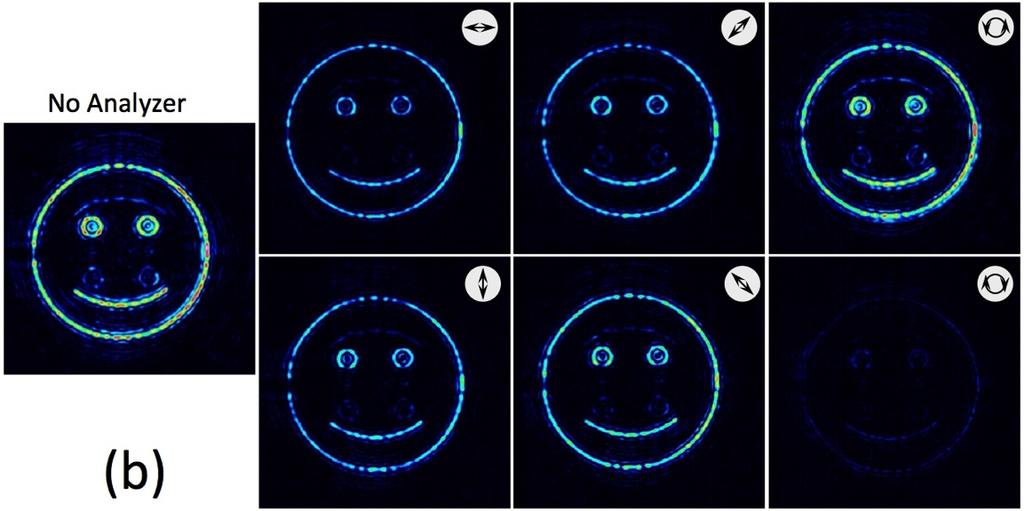
9 of d = 20 cm in Fig. 3(a) and of d = +20 cm in Fig. 3(c). Note that the virtual propagation can be of positive or negative distances, as already demonstrated in [14]. The three output reconstructions in Fig. 3 show a different scale due to the different encoded focal length F * (the Fresnel propagation does not change the scaling). This approach is therefore completely different to the change in scale achieved by using zoom lenses, as in [5,6]. 4.3 Control of the state of polarization In these previous experiments, we did not place the analyzer shown in Fig. 1, since the polarization state was not a concern. Next, we explore the polarization capabilities of the system. We again generate two copies of the hologram used in Fig. 3(b), so we simply apply the same pattern to the left and right halves of the LCSLM. This results in an output that is linearly polarized at 45 degrees. Experimental results are shown in Fig. 4(a). The case on the left shows the case without a polarization analyzer. The state of polarization becomes evident when we place six different polarization analyzers a linear polarizer analyzer oriented at 0, 45, 90, and 135 degrees and both left and right circular analyzers (LCP and RCP). We see that when the linear analyzer is oriented at -45 degrees, the hologram reconstruction is cancelled, indicating that the output is linearly polarized at +45 degrees. For all other analyzers, the full output reconstruction is retrieved. However, when a phase shift of π/2 is applied to the pattern on the right side (by uniformly adding the corresponding gray level to this side of the SLM), this results in a circularly polarized output, as shown in Fig. 4(b). Now we observe that the output disappears for the RCP analyzer, while it is fully transmitted for the LCP analyzer. For all linear polarizers the output is visible. This confirms that the hologram reconstruction is right circularly polarized, and confirms the polarization control. 5. Polarization logic 9
10 Finally, as a result demonstrating the potential of this system, an example of polarization-based logic operations is shown. We calculate two holograms from two smiling face patterns, but in one of them, the smile is removed. They have the same size and are encoded with the same focal length. Figure 5 shows the corresponding results when we use linear polarization analyzers. When the analyzers are oriented vertical and horizontal (Fig. 5(a) and Fig. 5(d)), the two patterns used in the holograms design are recovered: the complete smiling face for vertical polarization, and the face without the smile for horizontal polarization. Figures 5(b) and 5(e) correspond to the orientations of the linear polarization analyzers at +45 degrees and at -45 degrees respectively. In the first case, the result corresponds to the addition of the output reconstructions encoded in each (vertical and horizontal) polarization components. Figure 5(c) illustrates a diagram showing the addition operation. The outputs are encoded onto vertical and horizontal components of the electric field (vectors B and A respectively). These vectors project equally to the analyzer transmission axis when it is oriented at +45 degrees (resulting in the corresponding output vectors b and a ). Therefore, the addition of the two contributions is produced. This is not the case when the analyzer is oriented at -45 degrees, as Fig. 5(f) illustrates. Now the vertical and horizontal electric fields project to the orientation of the analyzer transmission axis in opposition, thus resulting in a subtraction operation. This is equivalent to the well-known operation of magneto-optic devices as binary phase-only modulators [23]. The output is now shown in Fig. 5(d), where only the difference between the two encoded outputs is observed, i.e., the smile. 6. Conclusions 10
11 In summary, we have experimentally demonstrated a proof-of-concept of a holographic projection system that combined two interesting features: 1) programmable control of the focusing plane and size of the reconstruction, and 2) programmable control of the state of polarization of the hologram reconstruction. The first feature is achieved thanks to the application of a technique [14], where the hologram plane is virtually propagated using a using Fresnel propagation algorithm, while being displayed in the same SLM. Using a previously reported angular spectrum algorithm [12] that allows fast calculations of the Fresnel propagated versions of the hologram. We have shown that this technique allows control of the axial position of the output reconstruction without changing the size. We have also shown that the technique also allows changing the size of the output reconstruction while keeping a fixed focusing plane. Note that this is fully achieved by encoding the Fourier transform lens function and the virtual displacement on the hologram displayed on the SLM, without requiring any additional zoom lens. The second feature, the polarization control, is achieved by using an optical system with a double pass through a LCSLM [10,11]. Two independent holograms can be displayed on each side of the SLM to control two orthogonal polarization components. This way we can apply the previously described Fourier encoded holograms to two independent patterns and provide a programmable control of the state of polarization of the holographic projection output. This can be an interesting property for 3D patterns visualization, where two images with orthogonal polarizations are required. Here, as an example, we have provided a demonstration of polarization-based logical operations, where the addition and subtraction of two images encoded on the two orthogonal linear polarizations is shown. We finally want to indicate some technological aspects where the system used here for demonstration could be adapted and made compact for practical application. First, note that the double-pass geometry in Fig. 1 implies the use of a beam-splitter, with the subsequent loss of power. Additionally this geometry forces us to divide the SLM screen in two parts, thus reducing the available space bandwidth and enlarging 11
12 the Nyquist focal length limit. This could be avoided simply using in cascade two transmissive SLMs as the prototype one used here. However, the SLM industry has moved to reflective liquid-crystal on silicon (LCOS) devices, with various newer high-resolution displays. An optical system similar to that in Fig. 1 can be built with LCOS-SLMs [24]. But since these are reflective devices, two beam-splitters would be required with substantial loss in intensity. Alternatively, LCOS-SLMs can be used with an angle, but then the system cannot be compact because requires enough room to separate the input and the reflected beam. We consider that the development of high-resolution transmissive parallel-aligned liquid-crystal SLMs could be of great interest for the practical implementation of the proposed technique, as well as for many others. Acknowledgements: IM and MMSL acknowledge financial support from Ministerio de Economía y Competitividad from Spain and FEDER Funds (ref. FIS C3-3-R) and from Conselleria d Educació, Investigació, Cultura i Esport, Generalitat Valenciana (ref. PROMETEO ). References [1]. E. Buckley, Holographic laser projection, J. Displ. Technol. 7(13), (2011). [2]. M. Makowski, I. Ducin, M. Sypek, A. Siemion, A. Siemion, J. Suszek, and A. Kolodziejczyk, Color image projection based on Fourier holograms, Opt. Lett. 35(8), (2010). [ [3]. A. Jesacher, S. Bernet, and M. Ritsch-Marte, Colour hologram projection with an SLM by exploiting its full phase modulation range, Opt. Express 22(17), (2014). [ [4]. J. Hecht, Cutting-edge cinema, Opt. & Photon. News 29(6), (2018). 12
13 [5]. H.-C. Lin, N. Collings, M.-S. Chen, and Y.-H. Lin, A holographic projection system with an electrically tuning and continuously adjustable optical zoom, Opt. Express 20(25), (2012). [ [6]. M.-S. Chen, N. Collings, H.-C. Lin, and Y.-H. Lin, A holographic projection system with an electrically adjustable optical zoom and a fixed location of zeroth-order diffraction, J. Displ. Technol. 10(6), (2014). [7]. J. A. Davis, T. I. Hall, I. Moreno, J. P. Sorger, D. M. Cottrell, Programmable zoom lens system with two spatial light modulators: Limits imposed by the spatial resolution, Appl. Sci. 8(6), 1006 (2018). [ [8]. T. Shimobaba, M. Makowski, T. Kakue, M. Oikawa, N. Okada, Y. Endo, R. Hirayama, and T. Ito, Lensless zoomable holographic projection using scaled Fresnel diffraction, Opt. Express 21(21), (2013). [ [9]. A. J. Woods, Crosstalk in stereoscopic displays: a review, J. Electron. Imaging 21(4), (2012). [ [10]. I. Moreno, J.A. Davis, T.M. Hernandez, D.M. Cottrell, and D. Sand, Complete polarization control of light from a liquid crystal spatial light modulator, Opt. Express 20(1), (2012). [ [11] J. A. Davis, I. Moreno, M. M. Sánchez-López, K. Badham, J. Albero, and D. M. Cottrell, Diffraction gratings generating orders with selective states of polarization, Opt. Express 24(2), (2016). [ [12]. J. A. Davis and D. M. Cottrell, Ray matrix analysis of the fast Fresnel transform with applications towards liquid crystal displays, Appl. Opt. 51(5), (2012). 13
14 [ [13]. J. Liang and M. F. Becker, Spatial bandwidth analysis of fast backward Fresnel diffraction for precise computer-generated hologram design, Appl. Opt. 53(27), G84-G94 (2014). [ [14]. J. A. Davis, I. Moreno, D. M. Cottrell, C. A. Berg, C. L. Freeman, A. Carmona, W. Debenham, Experimental implementation of a virtual optical beam propagator system based on a Fresnel diffraction algorithm, Opt. Eng. 54(10), (2015). [ [15]. J. L. Horner and P. D. Gianino, Phase-only matched filtering, Appl. Opt. 23(6), (1984). [ [16]. J. A. Davis, S. W. Flowers, D. M. Cottrell, and R. A. Lilly, Smoothing of the edge-enhanced impulse response from binary phase-only filters using random binary patterns, Appl. Opt. 28, (1989). [ [17]. F. Wyrowski, Diffractive optical elements: iterative calculation of quantized, blazed phase structures, J. Opt. Soc. Am. A 7(6), (1990). [ [18]. J. A. Davis, D. M. Cottrell, J. Campos, M. J. Yzuel, I. Moreno, Encoding amplitude information onto phase-only filters, Appl. Opt. 38(23), (1999). [ [19]. T. W. Clark, R. F. Offer, S. Franke-Arnold, A. S. Arnold, and N. Radwell, Comparison of beam generation techniques using a phase only spatial light modulator, Opt. Express 24(6), (2016). [ [20]. J. A. Davis, D. M. Cottrell, R. A. Lilly and S. W. Connely, Multiplexed phase-encoded lenses written on programmable spatial light modulators, Opt. Lett. 14, (1989). 14
15 [ [21]. J. A. Davis, M. A. Waring, G. W. Bach, R. A. Lilly and D. M. Cottrell, Compact optical correlator design, Appl. Opt. 28, (1989). [ [22]. J. W. Goodman, Introduction to Fourier Optics, McGraw Hill (1969). [23]. J. A. Davis, M. A. Waring, Contrast ratio improvement for the two-dimensional magneto-optic spatial light modulator, Appl. Opt. 31(29), (1992). [ [24]. X. Zheng, A. Lizana, A. Peinado, C. Ramírez, J. L. Martínez, A. Márquez, I. Moreno, J. Campos, Compact LCOS-SLM based polarization pattern beam generator, J. Lightwave Technol. 33(10), (2015). [ 15
16 Figure Captions Fig. 1. Double-pass system to generate polarization phase-only computer-generated holograms. The physical lens L3 can be removed and encoded onto the SLM. Fig. 2. Experimental demonstration of control of the focusing plane. Fourier lens encoded holograms are designed with focal lengths of F * = 50 cm (left) and F * = 75 cm (right). (a) Output at 50 cm from the SLM. (b) Output at 75 cm from the SLM. (c) Output at 75 cm when the left hologram is Fresnel propagated by a distance d = 25 cm. Fig. 3. Experimental demonstration of control of the size of the reconstruction. Detector is fixed, placed at a distance of 70 cm. The focal lengths of the encoded Fourier lens and virtual propagation distances are adjusted to keep a constant focus plane: (a) F * = 90 cm and d = 20 cm. (b) F * = 70 cm and d = 0 cm. (c) F * = 50 cm and d = +20 cm. Fig. 4. Experimental demonstration of control of the state of polarization. (a) Output linearly polarized at 45 degrees. (b) Output circularly polarized. Analyzers are indicated on each image. Fig. 5. Polarization logic: A and B denote the electric field orientations where the two holograms are encoded. a and b indicate the electric field orientations after the analyzer when oriented at ±45 degrees. (a)-(d) Experimental outputs for linear analyzers oriented vertical, at +45 degrees, horizontal, and at -45 degrees. Diagrams showing the projections of the electric fields in the cases of (e) addition and (f) subtraction of images. 16

17 Fig. 1

18 Fig. 2

19 Fig. 3

20 Fig. 4

21 Fig. 5
Complete polarization control of light from a liquid crystal spatial light modulator
 Complete polarization control of light from a liquid crystal spatial light modulator Ignacio Moreno, 1,* Jeffrey. Davis, 2 Travis M Hernandez, 2 Don M. Cottrell, 2 and David Sand 2 1. Departamento de Ciencia
arxiv: v1 [physics.optics] 1 Aug 2013
![arxiv: v1 [physics.optics] 1 Aug 2013](/thumbs/91/105313726.jpg "arxiv: v1 [physics.optics] 1 Aug 2013") arxiv:1308.0376v1 [physics.optics] 1 Aug 2013 Calculation reduction method for color computer-generated hologram using color space conversion Tomoyoshi Shimobaba 1, Takashi Kakue 1, Minoru Oikawa 1, Naoki
arxiv:1308.0376v1 [physics.optics] 1 Aug 2013 Calculation reduction method for color computer-generated hologram using color space conversion Tomoyoshi Shimobaba 1, Takashi Kakue 1, Minoru Oikawa 1, Naoki
Two pixel computer generated hologram using a zero twist nematic liquid crystal spatial light modulator
 Two pixel computer generated hologram using a zero twist nematic liquid crystal spatial light modulator Philip M. Birch, Rupert Young, David Budgett, Chris Chatwin School of Engineering, University of
arxiv: v1 [physics.optics] 1 Mar 2015
![arxiv: v1 [physics.optics] 1 Mar 2015](/thumbs/73/69509202.jpg "arxiv: v1 [physics.optics] 1 Mar 2015") Random phase-free kinoform for large objects arxiv:1503.00365v1 [physics.optics] 1 Mar 2015 Tomoyoshi Shimobaba, 1 Takashi Kakue, 1 Yutaka Endo, 1 Ryuji Hirayama, 1 Daisuke Hiyama, 1 Satoki Hasegawa, 1
Random phase-free kinoform for large objects arxiv:1503.00365v1 [physics.optics] 1 Mar 2015 Tomoyoshi Shimobaba, 1 Takashi Kakue, 1 Yutaka Endo, 1 Ryuji Hirayama, 1 Daisuke Hiyama, 1 Satoki Hasegawa, 1
Digital correlation hologram implemented on optical correlator
 Digital correlation hologram implemented on optical correlator David Abookasis and Joseph Rosen Ben-Gurion University of the Negev Department of Electrical and Computer Engineering P. O. Box 653, Beer-Sheva
Retardagraphy: A novel technique for optical recording of the. retardance pattern of an optical anisotropic object on a
 Retardagraphy: A novel technique for optical recording of the retardance pattern of an optical anisotropic object on a polarization-sensitive film using a single beam Daisuke Barada, 1,, Kiyonobu Tamura,
Generalized diffractive optical elements with asymmetric harmonic response and phase control
 Generalized diffractive optical elements with asymmetric harmonic response and phase control Jorge Albero, 1 Jeffrey A. Davis, 2 Don M. Cottrell, 2 Charles E. Granger, 2 Kyle R. McCormick, 2 and Ignacio
Invited Paper. Nukui-Kitamachi, Koganei, Tokyo, , Japan ABSTRACT 1. INTRODUCTION
 Invited Paper Wavefront printing technique with overlapping approach toward high definition holographic image reconstruction K. Wakunami* a, R. Oi a, T. Senoh a, H. Sasaki a, Y. Ichihashi a, K. Yamamoto
Shading of a computer-generated hologram by zone plate modulation
 Shading of a computer-generated hologram by zone plate modulation Takayuki Kurihara * and Yasuhiro Takaki Institute of Engineering, Tokyo University of Agriculture and Technology, 2-24-16 Naka-cho, Koganei,Tokyo
Fourier, Fresnel and Image CGHs of three-dimensional objects observed from many different projections
 Fourier, Fresnel and Image CGHs of three-dimensional objects observed from many different projections David Abookasis and Joseph Rosen Ben-Gurion University of the Negev Department of Electrical and Computer
HOLOEYE Photonics. HOLOEYE Photonics AG. HOLOEYE Corporation
 HOLOEYE Photonics Products and services in the field of diffractive micro-optics Spatial Light Modulator (SLM) for the industrial research R&D in the field of diffractive optics Micro-display technologies
Tutorial Solutions. 10 Holographic Applications Holographic Zone-Plate
 10 Holographic Applications 10.1 Holographic Zone-Plate Tutorial Solutions Show that if the intensity pattern for on on-axis holographic lens is recorded in lithographic film, then a one-plate results.
Supplementary Figure 1: Schematic of the nanorod-scattered wave along the +z. direction.
 Supplementary Figure 1: Schematic of the nanorod-scattered wave along the +z direction. Supplementary Figure 2: The nanorod functions as a half-wave plate. The fast axis of the waveplate is parallel to
Technologies of Digital Holographic Display
 Technologies of Digital Holographic Display Joonku Hahn Kyungpook National University Outline: 1. Classification of digital holographic display 2. Data capacity, View volume and Resolution 3. Holographic
Distortion Correction for Conical Multiplex Holography Using Direct Object-Image Relationship
 Proc. Natl. Sci. Counc. ROC(A) Vol. 25, No. 5, 2001. pp. 300-308 Distortion Correction for Conical Multiplex Holography Using Direct Object-Image Relationship YIH-SHYANG CHENG, RAY-CHENG CHANG, AND SHIH-YU
Multiple optical traps from a single laser beam using a mechanical element
 Multiple optical traps from a single laser beam using a mechanical element J.A. Dharmadhikari, A.K. Dharmadhikari, and D. Mathur * Tata Institute of Fundamental Research, 1 Homi Bhabha Road, Mumbai 400
Liquid Crystal Displays
 Liquid Crystal Displays Irma Alejandra Nicholls College of Optical Sciences University of Arizona, Tucson, Arizona U.S.A. 85721 iramirez@email.arizona.edu Abstract This document is a brief discussion of
Basic Polarization Techniques and Devices 1998, 2003 Meadowlark Optics, Inc
 Basic Polarization Techniques and Devices 1998, 2003 Meadowlark Optics, Inc This application note briefly describes polarized light, retardation and a few of the tools used to manipulate the polarization
Fresnel and Fourier digital holography architectures: a comparison.
 Fresnel and Fourier digital holography architectures: a comparison. Damien P., David S. Monaghan, Nitesh Pandey, Bryan M. Hennelly. Department of Computer Science, National University of Ireland, Maynooth,
Supplementary Figure 1 Optimum transmissive mask design for shaping an incident light to a desired
 Supplementary Figure 1 Optimum transmissive mask design for shaping an incident light to a desired tangential form. (a) The light from the sources and scatterers in the half space (1) passes through the
Diffractive optical elements with. square concentric rings of equal width
 Diffractive optical elements with square concentric rings of equal width Javier Alda 1, Luis Miguel Sanchez-Brea 2, Francisco Javier Salgado-Remacha 2, and José María Rico-García 2,3 Applied Optics Complutense
Hyperspectral interferometry for single-shot absolute measurement of 3-D shape and displacement fields
 EPJ Web of Conferences 6, 6 10007 (2010) DOI:10.1051/epjconf/20100610007 Owned by the authors, published by EDP Sciences, 2010 Hyperspectral interferometry for single-shot absolute measurement of 3-D shape
Limits of computational white-light holography
 Journal of Physics: Conference Series Limits of computational white-light holography To cite this article: Sebastian Mader et al 2013 J. Phys.: Conf. Ser. 415 012046 View the article online for updates
Supplementary materials of Multispectral imaging using a single bucket detector
 Supplementary materials of Multispectral imaging using a single bucket detector Liheng Bian 1, Jinli Suo 1,, Guohai Situ 2, Ziwei Li 1, Jingtao Fan 1, Feng Chen 1 and Qionghai Dai 1 1 Department of Automation,
specular diffuse reflection.
 Lesson 8 Light and Optics The Nature of Light Properties of Light: Reflection Refraction Interference Diffraction Polarization Dispersion and Prisms Total Internal Reflection Huygens s Principle The Nature
Chapter 2: Wave Optics
 Chapter : Wave Optics P-1. We can write a plane wave with the z axis taken in the direction of the wave vector k as u(,) r t Acos tkzarg( A) As c /, T 1/ and k / we can rewrite the plane wave as t z u(,)
OptiXplorer Optics experiments with an addressable Spatial Light Modulator (SLM) Dr. Andreas Hermerschmidt HOLOEYE Photonics AG
 Dr. Andreas Hermerschmidt HOLOEYE Photonics AG") OptiXplorer Optics experiments with an addressable Spatial Light Modulator (SLM) Dr. Andreas Hermerschmidt HOLOEYE Photonics AG Introduction Components based on optical technologies are used in more and
OptiXplorer Optics experiments with an addressable Spatial Light Modulator (SLM) Dr. Andreas Hermerschmidt HOLOEYE Photonics AG Introduction Components based on optical technologies are used in more and
Formulas of possible interest
 Name: PHYS 3410/6750: Modern Optics Final Exam Thursday 15 December 2011 Prof. Bolton No books, calculators, notes, etc. Formulas of possible interest I = ɛ 0 c E 2 T = 1 2 ɛ 0cE 2 0 E γ = hν γ n = c/v
Shift Multiplex Recording of Four-Valued Phase Data Pages by Volume Retardagraphy
 Appl. Sci. 2014, 4, 158-170; doi:10.3390/app4020158 Article OPEN ACCESS applied sciences ISSN 2076-3417 www.mdpi.com/journal/applsci Shift Multiplex Recording of Four-Valued Phase Data Pages by Volume
A digital holography technique for generating beams with arbitrary polarization and shape
 A digital holography technique for generating beams with arbitrary polarization and shape David aluenda a, Ignasi Juvells a, Rosario artínez-herrero b, Artur Carnicer a a Departament de Física Aplicada
White-light interference microscopy: minimization of spurious diffraction effects by geometric phase-shifting
 White-light interference microscopy: minimization of spurious diffraction effects by geometric phase-shifting Maitreyee Roy 1, *, Joanna Schmit 2 and Parameswaran Hariharan 1 1 School of Physics, University
Aberrations in Holography
 Aberrations in Holography D Padiyar, J Padiyar 1070 Commerce St suite A, San Marcos, CA 92078 dinesh@triple-take.com joy@triple-take.com Abstract. The Seidel aberrations are described as they apply to
Simulation study of phase retrieval for hard X-ray in-line phase contrast imaging
 450 Science in China Ser. G Physics, Mechanics & Astronomy 2005 Vol.48 No.4 450 458 Simulation study of phase retrieval for hard X-ray in-line phase contrast imaging YU Bin 1,2, PENG Xiang 1,2, TIAN Jindong
Spectrographs. C. A. Griffith, Class Notes, PTYS 521, 2016 Not for distribution.
 Spectrographs C A Griffith, Class Notes, PTYS 521, 2016 Not for distribution 1 Spectrographs and their characteristics A spectrograph is an instrument that disperses light into a frequency spectrum, which
Parallel two-step spatial carrier phase-shifting common-path interferometer with a Ronchi grating outside the Fourier plane
 Parallel two-step spatial carrier phase-shifting common-path interferometer with a Ronchi grating outside the Fourier plane Mingguang Shan, Bengong Hao, Zhi Zhong,* Ming Diao, and Yabin Zhang College of
An Intuitive Explanation of Fourier Theory
 An Intuitive Explanation of Fourier Theory Steven Lehar slehar@cns.bu.edu Fourier theory is pretty complicated mathematically. But there are some beautifully simple holistic concepts behind Fourier theory
Techniques of Noninvasive Optical Tomographic Imaging
 Techniques of Noninvasive Optical Tomographic Imaging Joseph Rosen*, David Abookasis and Mark Gokhler Ben-Gurion University of the Negev Department of Electrical and Computer Engineering P. O. Box 653,
Digital holographic display with two-dimensional and threedimensional convertible feature by high speed switchable diffuser
 https://doi.org/10.2352/issn.2470-1173.2017.5.sd&a-366 2017, Society for Imaging Science and Technology Digital holographic display with two-dimensional and threedimensional convertible feature by high
Final Exam. Today s Review of Optics Polarization Reflection and transmission Linear and circular polarization Stokes parameters/jones calculus
 Physics 42200 Waves & Oscillations Lecture 40 Review Spring 206 Semester Matthew Jones Final Exam Date:Tuesday, May 3 th Time:7:00 to 9:00 pm Room: Phys 2 You can bring one double-sided pages of notes/formulas.
A Single Grating-lens Focusing Two Orthogonally Polarized Beams in Opposite Direction
 , pp.41-45 http://dx.doi.org/10.14257/astl.2016.140.08 A Single Grating-lens Focusing Two Orthogonally Polarized Beams in Opposite Direction Seung Dae Lee 1 1* Dept. of Electronic Engineering, Namseoul
High spatial resolution measurement of volume holographic gratings
 High spatial resolution measurement of volume holographic gratings Gregory J. Steckman, Frank Havermeyer Ondax, Inc., 8 E. Duarte Rd., Monrovia, CA, USA 9116 ABSTRACT The conventional approach for measuring
Supporting Information for: Noninterleaved Metasurface for (2 6-1) Spin- and. Wavelength-Encoded Holograms
 Spin- and. Wavelength-Encoded Holograms") Supporting Information for: Noninterleaved Metasurface for (2 6-1) Spin- and Wavelength-Encoded Holograms Lei Jin 1,, Zhaogang Dong 2,, Shengtao Mei 1, Ye Feng Yu 3, Zhun Wei 1, Zhenying Pan 2,3, Soroosh
Supporting Information for: Noninterleaved Metasurface for (2 6-1) Spin- and Wavelength-Encoded Holograms Lei Jin 1,, Zhaogang Dong 2,, Shengtao Mei 1, Ye Feng Yu 3, Zhun Wei 1, Zhenying Pan 2,3, Soroosh
All forms of EM waves travel at the speed of light in a vacuum = 3.00 x 10 8 m/s This speed is constant in air as well
 Pre AP Physics Light & Optics Chapters 14-16 Light is an electromagnetic wave Electromagnetic waves: Oscillating electric and magnetic fields that are perpendicular to the direction the wave moves Difference
Projection of speckle patterns for 3D sensing
 Journal of Physics: Conference Series Projection of speckle patterns for 3D sensing To cite this article: J García et al 008 J. Phys.: Conf. Ser. 139 0106 View the article online for updates and enhancements.
Waves & Oscillations
 Physics 42200 Waves & Oscillations Lecture 40 Review Spring 2016 Semester Matthew Jones Final Exam Date:Tuesday, May 3 th Time:7:00 to 9:00 pm Room: Phys 112 You can bring one double-sided pages of notes/formulas.
Diffraction. Single-slit diffraction. Diffraction by a circular aperture. Chapter 38. In the forward direction, the intensity is maximal.
 Diffraction Chapter 38 Huygens construction may be used to find the wave observed on the downstream side of an aperture of any shape. Diffraction The interference pattern encodes the shape as a Fourier
TEAMS National Competition High School Version Photometry 25 Questions
 TEAMS National Competition High School Version Photometry 25 Questions Page 1 of 14 Telescopes and their Lenses Although telescopes provide us with the extraordinary power to see objects miles away, the
Chap. 4. Jones Matrix Method
 Chap. 4. Jones Matrix Method 4.1. Jones Matrix Formulation - For an incident light with a polarization state described by the Jones vector - Decompose the light into a linear combination of the "fast"
Exploiting scattering media for exploring 3D objects
 Exploiting scattering media for exploring 3D objects Alok Kumar Singh 1, Dinesh N Naik 1,, Giancarlo Pedrini 1, Mitsuo Takeda 1, 3 and Wolfgang Osten 1 1 Institut für Technische Optik and Stuttgart Research
Determining Wave-Optics Mesh Parameters for Complex Optical Systems
 Copyright 007 Society of Photo-Optical Instrumentation Engineers. This paper was published in SPIE Proc. Vol. 6675-7 and is made available as an electronic reprint with permission of SPIE. One print or
Image quality improvement of polygon computer generated holography
 Image quality improvement of polygon computer generated holography Xiao-Ning Pang, Ding-Chen Chen, Yi-Cong Ding, Yi-Gui Chen, Shao-Ji Jiang, and Jian-Wen Dong* School of Physics and Engineering, and State
Obtaining the curve Phase shift vs gray level of a spatial light modulator Holoeye LC2012
 Journal of Physics: Conference Series PAPER OPEN ACCESS Obtaining the curve Phase shift vs gray level of a spatial light modulator Holoeye LC2012 To cite this article: B Villalobos-Mendoza et al 2015 J.
Determining Wave-Optics Mesh Parameters for Modeling Complex Systems of Simple Optics
 Determining Wave-Optics Mesh Parameters for Modeling Complex Systems of Simple Optics Dr. Justin D. Mansell, Steve Coy, Liyang Xu, Anthony Seward, and Robert Praus MZA Associates Corporation Outline Introduction
Optics Vac Work MT 2008
 Optics Vac Work MT 2008 1. Explain what is meant by the Fraunhofer condition for diffraction. [4] An aperture lies in the plane z = 0 and has amplitude transmission function T(y) independent of x. It is
Holographic measurement and synthesis of optical field using a spatial light modulator
 Holographic measurement and synthesis of optical field using a spatial light modulator Joonku Hahn NCRCAPAS School of Electrical Engineering Seoul National University Introduction Overview of digital holography
Secondary grating formation by readout at Bragg-null incidence
 Secondary grating formation by readout at Bragg-null incidence Ali Adibi, Jose Mumbru, Kelvin Wagner, and Demetri Psaltis We show that when a dynamic hologram is read out by illumination at the Bragg nulls
Metallic Transmission Screen for Sub-wavelength Focusing
 Metallic Transmission Screen for Sub-wavelength Focusing A.M.H. Wong, C.D. Sarris and G.V. leftheriades Abstract: A simple metallic transmission screen is proposed that is capable of focusing an incident
Simple Spatial Domain Filtering
 Simple Spatial Domain Filtering Binary Filters Non-phase-preserving Fourier transform planes Simple phase-step filters (for phase-contrast imaging) Amplitude inverse filters, related to apodization Contrast
ratio of the volume under the 2D MTF of a lens to the volume under the 2D MTF of a diffraction limited
 SUPPLEMENTARY FIGURES.9 Strehl ratio (a.u.).5 Singlet Doublet 2 Incident angle (degree) 3 Supplementary Figure. Strehl ratio of the singlet and doublet metasurface lenses. Strehl ratio is the ratio of
Waves & Oscillations
 Physics 42200 Waves & Oscillations Lecture 41 Review Spring 2013 Semester Matthew Jones Final Exam Date:Tuesday, April 30 th Time:1:00 to 3:00 pm Room: Phys 112 You can bring two double-sided pages of
TEAMS National Competition Middle School Version Photometry 25 Questions
 TEAMS National Competition Middle School Version Photometry 25 Questions Page 1 of 13 Telescopes and their Lenses Although telescopes provide us with the extraordinary power to see objects miles away,
Comparison of Beam Shapes and Transmission Powers of Two Prism Ducts
 Australian Journal of Basic and Applied Sciences, 4(10): 4922-4929, 2010 ISSN 1991-8178 Comparison of Beam Shapes and Transmission Powers of Two Prism Ducts 1 Z. Emami, 2 H. Golnabi 1 Plasma physics Research
Conversion of evanescent waves into propagating waves by vibrating knife edge
 1 Conversion of evanescent waves into propagating waves by vibrating knife edge S. Samson, A. Korpel and H.S. Snyder Department of Electrical and Computer Engineering, 44 Engineering Bldg., The University
UNIT VI OPTICS ALL THE POSSIBLE FORMULAE
 58 UNIT VI OPTICS ALL THE POSSIBLE FORMULAE Relation between focal length and radius of curvature of a mirror/lens, f = R/2 Mirror formula: Magnification produced by a mirror: m = - = - Snell s law: 1
A Comparison of the Iterative Fourier Transform Method and. Evolutionary Algorithms for the Design of Diffractive Optical.
 A Comparison of the Iterative Fourier Transform Method and Evolutionary Algorithms for the Design of Diffractive Optical Elements Philip Birch, Rupert Young, Maria Farsari, David Budgett, John Richardson,
Computer-originated planar holographic optical elements
 Computer-originated planar holographic optical elements Silviu Reinhorn, Yaakov Amitai, and Albert A. Friesem We present novel, to our knowledge, methods for the analytical design and recording of planar
Experimental Observation of Invariance of Spectral Degree of Coherence. with Change in Bandwidth of Light
 Experimental Observation of Invariance of Spectral Degree of Coherence with Change in Bandwidth of Light Bhaskar Kanseri* and Hem Chandra Kandpal Optical Radiation Standards, National Physical Laboratory,
SIMULATION AND VISUALIZATION IN THE EDUCATION OF COHERENT OPTICS
 SIMULATION AND VISUALIZATION IN THE EDUCATION OF COHERENT OPTICS J. KORNIS, P. PACHER Department of Physics Technical University of Budapest H-1111 Budafoki út 8., Hungary e-mail: kornis@phy.bme.hu, pacher@phy.bme.hu
Chapter 3 Geometric Optics
 Chapter 3 Geometric Optics [Reading assignment: Goodman, Fourier Optics, Appendix B Ray Optics The full three dimensional wave equation is: (3.) One solution is E E o ûe i ωt± k r ( ). This is a plane
Fast Response Fresnel Liquid Crystal Lens for 2D/3D Autostereoscopic Display
 Invited Paper Fast Response Fresnel Liquid Crystal Lens for 2D/3D Autostereoscopic Display Yi-Pai Huang* b, Chih-Wei Chen a, Yi-Ching Huang a a Department of Photonics & Institute of Electro-Optical Engineering,
Digital Pulse Acoustic Lensless Fourier Method for Ultrasonic Imaging
 Bulg. J. Phys. 34 (2007) 59 70 Digital Pulse Acoustic Lensless Fourier Method for Ultrasonic Imaging A. Andreeva, M. Burova, J. Burov Faculty of Physics, University of Sofia, 5 James Bourchier Blvd., Sofia
Optics Final Exam Name
 Instructions: Place your name on all of the pages. Do all of your work in this booklet. Do not tear off any sheets. Show all of your steps in the problems for full credit. Be clear and neat in your work.
Two-dimensional optical wavelet decomposition with white-light illumination by wavelength multiplexing
 Esteve-aboada et al. Vol. 18, No. 1/January 2001/J. Opt. Soc. Am. A 157 wo-dimensional optical wavelet decomposition with white-light illumination by wavelength multiplexing José J. Esteve-aboada, Javier
Holographic elements for Fourier transform
 Optica Applicata, Vol. XXXIV, No. 1, 2004 Holographic elements for Fourier transform EUGENIUSZ JAGOSZEWSKI, ANDRZEJ ANDRUCHÓW Institute of Physics, Wrocław University of Technology, Wybrzeże Wyspiańskiego
Rotation-invariant optical recognition of three-dimensional objects
 Rotation-invariant optical recognition of three-dimensional objects José J. Esteve-Taboada, Javier García, and Carlos Ferreira An automatic method for rotation-invariant three-dimensional 3-D object recognition
9. Polarizers. Index of. Coefficient of Material Wavelength ( ) Brewster angle refraction (n)
 Brewster angle refraction (n)") 9. Polarizers All polarized light is to some degree elliptical in nature. Basic states of polarization like linear and circular are actually special cases of elliptically polarized light which is defined
9. Polarizers All polarized light is to some degree elliptical in nature. Basic states of polarization like linear and circular are actually special cases of elliptically polarized light which is defined
Null test for a highly paraboloidal mirror
 Null test for a highly paraboloidal mirror Taehee Kim, James H. Burge, Yunwoo Lee, and Sungsik Kim A circular null computer-generated hologram CGH was used to test a highly paraboloidal mirror diameter,
Holographic digital data storage using phasemodulated
 Holographic digital data storage using phasemodulated pixels Renu John, Joby Joseph, Kehar Singh* Photonics Group, Department of Physics, Indian Institute of Technology, Delhi, New Delhi 110 016, India
Synthesis of a multiple-peak spatial degree of coherence for imaging through absorbing media
 Synthesis of a multiple-peak spatial degree of coherence for imaging through absorbing media Mark Gokhler and Joseph Rosen The synthesis of a multiple-peak spatial degree of coherence is demonstrated.
Real-time relighting of digital holograms based on wavefront recording plane method
 Real-time relighting of digital holograms based on avefront recording plane method P.W.M. Tsang, 1,* K.W.K. Cheung, 1 and T.-C Poon 2 1 Department of Electronic Engineering, City University of Hong Kong,
Basic Optics : Microlithography Optics Part 4: Polarization
 Electromagnetic Radiation Polarization: Linear, Circular, Elliptical Ordinary and extraordinary rays Polarization by reflection: Brewster angle Polarization by Dichroism Double refraction (Birefringence)
Physics 123 Optics Review
 Physics 123 Optics Review I. Definitions & Facts concave converging convex diverging real image virtual image real object virtual object upright inverted dispersion nearsighted, farsighted near point,
PHYSICS 213 PRACTICE EXAM 3*
 PHYSICS 213 PRACTICE EXAM 3* *The actual exam will contain EIGHT multiple choice quiz-type questions covering concepts from lecture (16 points), ONE essay-type question covering an important fundamental
Interferometric method for phase calibration in liquid crystal spatial light modulators using a self-generated diffraction-grating
 Interferometric method for phase calibration in liquid crystal spatial light modulators using a self-generated diffraction-grating José Luis Martínez Fuentes, 1,2,3 Enrique J. Fernández, 2 Pedro M. Prieto,
Algorithm for Implementing an ABCD Ray Matrix Wave-Optics Propagator
 Copyright 007 Society of Photo-Optical Instrumentation Engineers. This paper was published in SPIE Proc. Vol. 6675-6 and is made available as an electronic reprint with permission of SPIE. One print or
LED holographic imaging by spatial-domain diffraction computation of. textured models
 LED holographic imaging by spatial-domain diffraction computation of textured models Ding-Chen Chen, Xiao-Ning Pang, Yi-Cong Ding, Yi-Gui Chen, and Jian-Wen Dong* School of Physics and Engineering, and
25 The vibration spiral
 25 The vibration spiral Contents 25.1 The vibration spiral 25.1.1 Zone Plates............................... 10 25.1.2 Circular obstacle and Poisson spot.................. 13 Keywords: Fresnel Diffraction,
Title. Author(s)Yamaguchi, Kazuhiro; Sakamoto, Yuji. CitationApplied Optics, 48(34): H203-H211. Issue Date Doc URL. Rights.
Yamaguchi, Kazuhiro; Sakamoto, Yuji. CitationApplied Optics, 48(34): H203-H211. Issue Date Doc URL. Rights.") Title Computer generated hologram with characteristics of Author(s)Yamaguchi, Kazuhiro; Sakamoto, Yuji CitationApplied Optics, 48(34): H203-H211 Issue Date 2009-12-01 Doc URL http://hdl.handle.net/2115/52148
Title Computer generated hologram with characteristics of Author(s)Yamaguchi, Kazuhiro; Sakamoto, Yuji CitationApplied Optics, 48(34): H203-H211 Issue Date 2009-12-01 Doc URL http://hdl.handle.net/2115/52148
Holography. How is that different than photography? How is it accomplished? Amplitude & Phase
 Holography 1948: Dennis Gabor proposes lensless imaging: wavefront reconstruction. Calls it total recording or Holo gram Concept: record and recreate wavefront incident on film. Amplitude & Phase How is
9. Polarization. 1) General observations [Room 310]
![9. Polarization. 1) General observations [Room 310]](/thumbs/74/70594885.jpg "9. Polarization. 1) General observations [Room 310]") 9. Polarization In this lab we are going to study the various phenomena related to the polarization of light. We will also learn how to analyze, control and transfer the polarization state of light. This
9. Polarization In this lab we are going to study the various phenomena related to the polarization of light. We will also learn how to analyze, control and transfer the polarization state of light. This
The branch of physics which studies light
 Mr.V The branch of physics which studies light Geometric model XVI century by W Snell Wave Model XIX century by JC Maxwell Photon Model XX century by Planck, Einstein Models of Light Basic Concept Laws
Single Photon Interference
 December 19, 2006 D. Lancia P. McCarthy Classical Interference Intensity Distribution Overview Quantum Mechanical Interference Probability Distribution Which Path? The Effects of Making a Measurement Wave-Particle
Light: Geometric Optics
 Light: Geometric Optics The Ray Model of Light Light very often travels in straight lines. We represent light using rays, which are straight lines emanating from an object. This is an idealization, but
Vibration parameter measurement using the temporal digital hologram sequence and windowed Fourier transform
 THEORETICAL & APPLIED MECHANICS LETTERS 1, 051008 (2011) Vibration parameter measurement using the temporal digital hologram sequence and windowed Fourier transform Chong Yang, 1, 2 1, a) and Hong Miao
ONE MARK QUESTIONS GEOMETRICAL OPTICS QUESTION BANK
 ONE MARK QUESTIONS 1. What is lateral shift? 2. What should be the angle of incidence to have maximum lateral shift? 3. For what angle, lateral shift is minimum? 4. What is Normal shift? 5. What is total
OPSE FINAL EXAM Fall CLOSED BOOK. Two pages (front/back of both pages) of equations are allowed.
 of equations are allowed.") CLOSED BOOK. Two pages (front/back of both pages) of equations are allowed. YOU MUST SHOW YOUR WORK. ANSWERS THAT ARE NOT JUSTIFIED WILL BE GIVEN ZERO CREDIT. ALL NUMERICAL ANSERS MUST HAVE UNITS INDICATED.
CLOSED BOOK. Two pages (front/back of both pages) of equations are allowed. YOU MUST SHOW YOUR WORK. ANSWERS THAT ARE NOT JUSTIFIED WILL BE GIVEN ZERO CREDIT. ALL NUMERICAL ANSERS MUST HAVE UNITS INDICATED.
AP* Optics Free Response Questions
 AP* Optics Free Response Questions 1978 Q5 MIRRORS An object 6 centimeters high is placed 30 centimeters from a concave mirror of focal length 10 centimeters as shown above. (a) On the diagram above, locate
Supplementary Information
 Supplementary Information Interferometric scattering microscopy with polarization-selective dual detection scheme: Capturing the orientational information of anisotropic nanometric objects Il-Buem Lee
Chapter 37. Wave Optics
 Chapter 37 Wave Optics Wave Optics Wave optics is a study concerned with phenomena that cannot be adequately explained by geometric (ray) optics. Sometimes called physical optics These phenomena include:
3.6 Rotational-Shearing Interferometry for Improved Target Characterization
 3.6 Rotational-Shearing Interferometry for Improved Target Characterization Inertial-fusion targets have strict requirements regarding sphericity, surface smoothness, and layer-thickness uniformity. During