Holography. How is that different than photography? How is it accomplished? Amplitude & Phase
|
|
|
- Anthony Gray
- 6 years ago
- Views:
Transcription
1
2 Holography 1948: Dennis Gabor proposes lensless imaging: wavefront reconstruction. Calls it total recording or Holo gram Concept: record and recreate wavefront incident on film. Amplitude & Phase How is that different than photography? How is it accomplished? Inclusion of a reference wave, record the interference, capture the phase.
3 Holography Invented in 1948 by Dennis Gabor for use in electron microscopy, before the invention of the laser Leith and Upatnieks (1962) applied laser light to holography and introduced an important off-axis technique
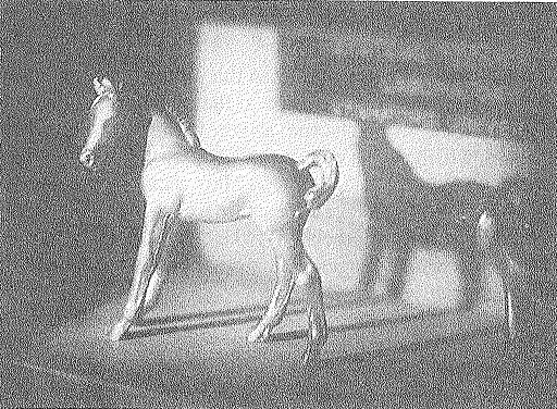
4 History Continued In 1962 Emmett Leith and Juris Upatnieks realized that holography could be used as a 3-D visual medium From their work, they used a laser to create the first hologram in history, that of a toy train and bird This type of hologram required laser light to be viewed, though.
5 White Light and High Speed Objects In 1962 Dr. Uri Denisyuk of the former U.S.S.R. developed a white light reflection hologram, which could be viewed in light from a normal incandescent bulb. In 1960, with the invention of the pulsedruby laser, holograms of high speed objects was made possible
6
7 Conventional vs. Holographic photography Conventional: 2-d version of a 3-d scene: irradiance map Photograph lacks depth perception or parallax Film sensitive only to radiant energy Phase relation (i.e. interference) are lost
8 Conventional vs. Holographic photography Hologram: Freezes the intricate wavefront of light that carries all the visual information of the scene To view a hologram, the wavefront is reconstructed View what we would have seen if present at the original scene through the window defined by the hologram Provides depth perception and parallax
9 Conventional vs. Holographic photography Hologram: Converts phase information into amplitude information (in-phase - maximum amplitude, out-ofphase minimum amplitude) Interfere wavefront of light from a scene with a reference wave The hologram is a complex interference pattern of microscopically spaced fringes holos Greek for whole message
10 Hologram of a point source Construction of the hologram of a point source Any object can be represented as a collection of points Photographic plate Reference wave - plane x Photosensitive plate 1. Records interference pattern (linear response) 2. Emulsion has small grain structure () y z Object wave - spherical
11 Point object hologram construction: Intensity distribution on plate Reference wave Object wave Intensity distribution on plate R O OR RR OO R O y x I z y x r where oe e z y x o z y x O re e z y x r z y x R ikr z y x i ikz z y x i * * * * ),, ( ),, ( ), ( ),, ( ),, ( ),, ( ),, (
12 Hologram construction I( x, y, z) r 2 o 2 2or cos( ) Fresnel zone plate z 0 film plane I( x, y) r 2 o 2 2or cos( kr) Maxima for kr=2m or r=m i.e. if the OPL difference OZ OP is an integral number of wavelengths, the reference beam arrives at P in step with the scattered (i.e. object) beam.
13 Hologram When developed the photographic plate will have a transmittance which depends on the intensity distribution in the recorded plate * t tb B( O O R 2 OR * ) t b background transmittance due to R 2 term B parameter which is a function of the recording and developing process
14 Hologram reconstruction When illuminated by a coherent wave, A(x,y), known as the reconstruction wave, the optical field emerging from the transparency is, A( x, y) t p t b A BOO * A BO * RA BOR * A i.e. a superposition of 4 waves If A(x,y)=R(x,y), i.e. reconstruction and reference waves are identical, R( x, y) t p ( t b BOO * ) R BR 2 O * B R 2 O
15 Hologram reconstruction Three terms in the reconstructed wave 2 * R( x, y) t ( t BOO * ) R BR O p b B R 2 O Direct wave identical to reference wave except for an overall change in amplitude Conjugate wave complex conjugate of object wave displaced by a phase angle 2 Object wave identical to object wave except for a change in intensity
16 Hologram reconstruction Three terms in the reconstructed wave of the point hologram R 2 ikz i2kz ikr ( x, y) t p ( tb B o ) e Be e B r 2 e ikr Direct wave identical to reference wave (propagates along z) except for an overall change in amplitude Conjugate wave spherical wave collapsing to a point at a distance z to the right of the hologram -a real image - displaced by a phase angle 2kz Object wave Spherical wave except for a change in intensity B r 2 i.e. reconstructed wavefront
17 Direct, object and conjugate waves Reference wave Object wave Real image Virtual image Conjugate wave Direct wave -z z z=0
18 Hologram : Direct, object and conjugate waves Direct wave: corresponds to zeroth order grating diffraction pattern Object wave: gives virtual image of the object (reconstructs object wavefront) first order diffraction Conjugate wave: conjugate point, real image (not useful since image is inside-out due to negative phase angle) first order diffraction In general, we wish to view only the object wave the other waves just confuse the issue
19 Off-axis- Direct, object and conjugate waves Use an off-axis system to record the hologram, ensuring separation of the three waves on reconstruction Reference wave Object wave Direct wave Virtual image Conjugate wave Real image
20 Holography
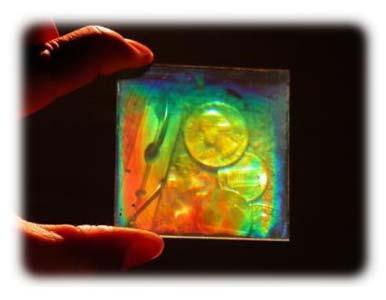
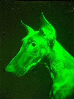
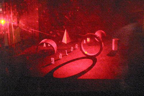
21 Hologram Playback Images are formed when light is projected through the hologram. The observer sees a virtual image formed behind the hologram.

22 Hologram and images


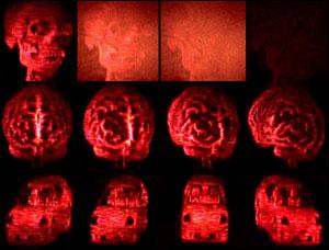
23 Sum of the Parts? Every part of a hologram contains the image of the whole object. You can cut off the corner of a hologram and see the entire image through it. For every viewing angle you see the image in a different perspective, as you would a real object. Each piece of a hologram contains a particular perspective of the image, but it includes the entire object. The top image is the view through the larger part of the hologram, while the bottom image is through a small corner cut off the hologram. The view through the small corner is from a particular point of view, but contains the whole object.
24 Hologram: Wavelength With a different color, the virtual image will appear at a different angle (i.e. as a grating, the hologram disperses light of different wavelengths at different angles) Volume hologram: emulsion thickness >> fringe spacing Can be used to reproduce images in their original color when illuminated by white light. Use multiple exposures of scene in three primary colors (R,G,B)
25 Hologram Reflection vs. Transmission Transmission hologram: reference and object waves traverse the film from the same side Reflection hologram: reference and object waves traverse the emulsion from opposite sides View in Transmission View in reflection


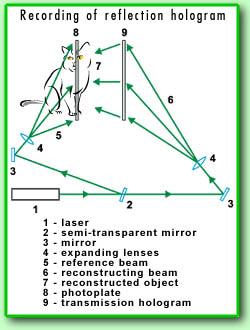
26 Recording of Types of Holograms
27 White light reflection holography laser reference wave object wave lamp
28 Hologram: Some Applications Microscopy M = r / s Increase magnification by viewing hologram with longer wavelength Produce hologram with x-ray laser, when viewed with visible light M ~ d images of microscopic objects DNA, viruses Interferometry Small changes in OPL can be measured by viewing the direct image of the object and the holographic image (interference pattern produce finges Δl) E.g. stress points, wings of fruit fly in motion, compression waves around a speeding bullet, convection currents around a hot filament

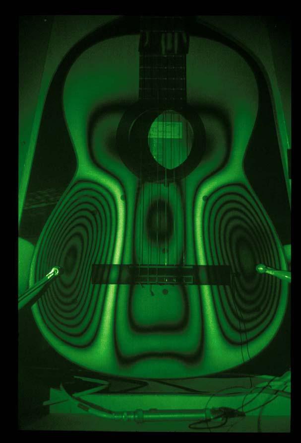
29 Vibrating Surface

30 Holographic Storage
16. Holography. Dennis Gabor (1947) Nobel Prize in Physics (1971)
 Nobel Prize in Physics (1971)") 16. Holography Dennis Gabor (1947) Nobel Prize in Physics (1971) Photography Records intensity distribution of light. Does not record direction. Two-dimensional image. Holography = whole + writing Records
16. Holography Dennis Gabor (1947) Nobel Prize in Physics (1971) Photography Records intensity distribution of light. Does not record direction. Two-dimensional image. Holography = whole + writing Records
Digitalna Holografija i Primjene
 Digitalna Holografija i Primjene Hrvoje Skenderović Institut za fiziku 5. PIF Radionica, IRB, 16.12.2014. Holography Dennis Gabor invented holography in 1948 as a method for recording and reconstructing
Holography & Coherence For Holography need coherent beams Two waves coherent if fixed phase relationship between them for some period of time
 Holography & Coherence For Holography need coherent beams Two waves coherent if fixed phase relationship between them for some period of time Coherence Coherence appear in two ways Spatial Coherence Waves
Holography 24th October 2005
 24th October 2005 Contents 1 Introduction 4 2 Wavefront Reconstruction 4 2.1 Recording Amplitude and Phase................. 4 2.2 The Recording Medium...................... 6 2.2.1 Amplitude Transmittance
HoloGraphics. Combining Holograms with Interactive Computer Graphics
 HoloGraphics Combining Holograms with Interactive Computer Graphics Gordon Wetzstein Bauhaus University Weimar [gordon.wetzstein@medien.uni-weimar.de] 1 Location Weimar Dunedin Courtesy: NASA 2 HoloGraphics
Tutorial Solutions. 10 Holographic Applications Holographic Zone-Plate
 10 Holographic Applications 10.1 Holographic Zone-Plate Tutorial Solutions Show that if the intensity pattern for on on-axis holographic lens is recorded in lithographic film, then a one-plate results.
Part 7 Holography. Basic Hologram Setup
 Part 7 Holography Basic Holographic Technique Light Sources Recording Materials Holographic Non-Destructive Testing Real-Time Double-Exposure Time-Average 2000 - James C. Wyant Part 7 Page 1 of 28 Basic
Chapter 2: Wave Optics
 Chapter : Wave Optics P-1. We can write a plane wave with the z axis taken in the direction of the wave vector k as u(,) r t Acos tkzarg( A) As c /, T 1/ and k / we can rewrite the plane wave as t z u(,)
Chapter 8: Physical Optics
 Chapter 8: Physical Optics Whether light is a particle or a wave had puzzled physicists for centuries. In this chapter, we only analyze light as a wave using basic optical concepts such as interference
Solution to the Twin Image Problem in Holography
 1 Solution to the Twin Image Problem in Holography Tatiana Latychevskaia & Hans-Werner Fink Institute of Physics, University of Zurich, Winterthurerstrasse 190, CH-8057, Switzerland While the invention
Introduction to Computer-Based Holography
 Mitglied der Helmholtz-Gemeinschaft Introduction to Computer-Based Holography October 29, 2013 Carsten Karbach, Jülich Supercomputing Centre (JSC) Why computergenerated holography? Applications Source:
PHYSICS. Chapter 33 Lecture FOR SCIENTISTS AND ENGINEERS A STRATEGIC APPROACH 4/E RANDALL D. KNIGHT
 PHYSICS FOR SCIENTISTS AND ENGINEERS A STRATEGIC APPROACH 4/E Chapter 33 Lecture RANDALL D. KNIGHT Chapter 33 Wave Optics IN THIS CHAPTER, you will learn about and apply the wave model of light. Slide
DIFFRACTION 4.1 DIFFRACTION Difference between Interference and Diffraction Classification Of Diffraction Phenomena
 4.1 DIFFRACTION Suppose a light wave incident on a slit AB of sufficient width b, as shown in Figure 1. According to concept of rectilinear propagation of light the region A B on the screen should be uniformly
Diffraction. Factors that affect Diffraction
 Diffraction What is one common property the four images share? Diffraction: Factors that affect Diffraction TELJR Publications 2017 1 Young s Experiment AIM: Does light have properties of a particle? Or
Basic optics. Geometrical optics and images Interference Diffraction Diffraction integral. we use simple models that say a lot! more rigorous approach
 Basic optics Geometrical optics and images Interference Diffraction Diffraction integral we use simple models that say a lot! more rigorous approach Basic optics Geometrical optics and images Interference
Aberrations in Holography
 Aberrations in Holography D Padiyar, J Padiyar 1070 Commerce St suite A, San Marcos, CA 92078 dinesh@triple-take.com joy@triple-take.com Abstract. The Seidel aberrations are described as they apply to
1 Laboratory #4: Division-of-Wavefront Interference
 1051-455-0073, Physical Optics 1 Laboratory #4: Division-of-Wavefront Interference 1.1 Theory Recent labs on optical imaging systems have used the concept of light as a ray in goemetrical optics to model
AP Physics Problems -- Waves and Light
 AP Physics Problems -- Waves and Light 1. 1975-4 (Physical Optics) a. Light of a single wavelength is incident on a single slit of width w. (w is a few wavelengths.) Sketch a graph of the intensity as
Shading of a computer-generated hologram by zone plate modulation
 Shading of a computer-generated hologram by zone plate modulation Takayuki Kurihara * and Yasuhiro Takaki Institute of Engineering, Tokyo University of Agriculture and Technology, 2-24-16 Naka-cho, Koganei,Tokyo
Chapter 24 - The Wave Nature of Light
 Chapter 24 - The Wave Nature of Light Summary Four Consequences of the Wave nature of Light: Diffraction Dispersion Interference Polarization Huygens principle: every point on a wavefront is a source of
Waves & Oscillations
 Physics 42200 Waves & Oscillations Lecture 37 Interference Spring 2016 Semester Matthew Jones Multiple Beam Interference In many situations, a coherent beam can interfere with itself multiple times Consider
Chapter 24 The Wave Nature of Light
 Chapter 24 The Wave Nature of Light 24.1 Waves Versus Particles; Huygens Principle and Diffraction Huygens principle: Every point on a wave front acts as a point source; the wavefront as it develops is
specular diffuse reflection.
 Lesson 8 Light and Optics The Nature of Light Properties of Light: Reflection Refraction Interference Diffraction Polarization Dispersion and Prisms Total Internal Reflection Huygens s Principle The Nature
Invited Paper. Nukui-Kitamachi, Koganei, Tokyo, , Japan ABSTRACT 1. INTRODUCTION
 Invited Paper Wavefront printing technique with overlapping approach toward high definition holographic image reconstruction K. Wakunami* a, R. Oi a, T. Senoh a, H. Sasaki a, Y. Ichihashi a, K. Yamamoto
E x Direction of Propagation. y B y
 x E x Direction of Propagation k z z y B y An electromagnetic wave is a travelling wave which has time varying electric and magnetic fields which are perpendicular to each other and the direction of propagation,
f. (5.3.1) So, the higher frequency means the lower wavelength. Visible part of light spectrum covers the range of wavelengths from
 So, the higher frequency means the lower wavelength. Visible part of light spectrum covers the range of wavelengths from") Lecture 5-3 Interference and Diffraction of EM Waves During our previous lectures we have been talking about electromagnetic (EM) waves. As we know, harmonic waves of any type represent periodic process
Lecture 5-3 Interference and Diffraction of EM Waves During our previous lectures we have been talking about electromagnetic (EM) waves. As we know, harmonic waves of any type represent periodic process
UNIT VI OPTICS ALL THE POSSIBLE FORMULAE
 58 UNIT VI OPTICS ALL THE POSSIBLE FORMULAE Relation between focal length and radius of curvature of a mirror/lens, f = R/2 Mirror formula: Magnification produced by a mirror: m = - = - Snell s law: 1
Lecture PowerPoints. Chapter 24 Physics: Principles with Applications, 7 th edition Giancoli
 Lecture PowerPoints Chapter 24 Physics: Principles with Applications, 7 th edition Giancoli This work is protected by United States copyright laws and is provided solely for the use of instructors in teaching
High spatial resolution measurement of volume holographic gratings
 High spatial resolution measurement of volume holographic gratings Gregory J. Steckman, Frank Havermeyer Ondax, Inc., 8 E. Duarte Rd., Monrovia, CA, USA 9116 ABSTRACT The conventional approach for measuring
Interference of Light
 Interference of Light Review: Principle of Superposition When two or more waves interact they interfere. Wave interference is governed by the principle of superposition. The superposition principle says
Control of Light. Emmett Ientilucci Digital Imaging and Remote Sensing Laboratory Chester F. Carlson Center for Imaging Science 8 May 2007
 Control of Light Emmett Ientilucci Digital Imaging and Remote Sensing Laboratory Chester F. Carlson Center for Imaging Science 8 May 007 Spectro-radiometry Spectral Considerations Chromatic dispersion
Diffraction. Light bends! Diffraction assumptions. Solution to Maxwell's Equations. The far-field. Fraunhofer Diffraction Some examples
 Diffraction Light bends! Diffraction assumptions Solution to Maxwell's Equations The far-field Fraunhofer Diffraction Some examples Diffraction Light does not always travel in a straight line. It tends
G3 TWO-SOURCE INTERFERENCE OF WAVES
 G3 TWO-SOURCE INTERFERENCE OF WAVES G4 DIFFRACTION GRATINGS HW/Study Packet Required: READ Tsokos, pp 624-631 SL/HL Supplemental: Hamper, pp 424-428 DO Questions pp 631-632 #1,3,8,9,10 REMEMBER TO. Work
To see how a sharp edge or an aperture affect light. To analyze single-slit diffraction and calculate the intensity of the light
 Diffraction Goals for lecture To see how a sharp edge or an aperture affect light To analyze single-slit diffraction and calculate the intensity of the light To investigate the effect on light of many
A 4. An electromagnetic wave travelling through a transparent medium is given by y. in S units. Then what is the refractive index of the medium?
 SECTION (A) : PRINCIPLE OF SUPERPOSITION, PATH DIFFERENCE, WAVEFRONTS, AND COHERENCE A 1. Two sources of intensity I & 4I are used in an interference experiment. Find the intensity at points where the
The topics are listed below not exactly in the same order as they were presented in class but all relevant topics are on the list!
 Ph332, Fall 2016 Study guide for the final exam, Part Two: (material lectured before the Nov. 3 midterm test, but not used in that test, and the material lectured after the Nov. 3 midterm test.) The final
Interference. Electric fields from two different sources at a single location add together. The same is true for magnetic fields at a single location.
 Interference Electric fields from two different sources at a single location add together. The same is true for magnetic fields at a single location. Thus, interacting electromagnetic waves also add together.
Physical Optics. 1 st year physics laboratories. University of Ottawa.
 Physical Optics 1 st year physics laboratories University of Ottawa https://uottawa.brightspace.com/d2l/home INTRODUCTION Physical optics deals with light as a wave which can bend around obstacles (diffraction)
ECE 4606 Undergraduate Optics Lab Holography. Holography. Outline. Subject of the Nobel prize in Physics to Gabor in 1971
 Holography C 4606 Undergraduate ptics Lab Holography utline Subject of the Nobel prize in Physics to Gabor in 1971 Basics Thin absorption holograms More considerations for thin holograms obert. McLeod,
Experiment 5: Polarization and Interference
 Experiment 5: Polarization and Interference Nate Saffold nas2173@columbia.edu Office Hour: Mondays, 5:30PM-6:30PM @ Pupin 1216 INTRO TO EXPERIMENTAL PHYS-LAB 1493/1494/2699 Introduction Outline: Review
Physics 309 Lab 3. where the small angle approximation has been used. This pattern has maxima at. Y Max. n L /d (2)
") Physics 309 Lab 3 Introduction This will be a lab whose purpose is to give you some hands-on experience with optical interference and diffraction, using small green diode lasers as the light sources. Each
Physics 309 Lab 3 Introduction This will be a lab whose purpose is to give you some hands-on experience with optical interference and diffraction, using small green diode lasers as the light sources. Each
Ray Optics. Lecture 23. Chapter 23. Physics II. Course website:
 Lecture 23 Chapter 23 Physics II Ray Optics Course website: http://faculty.uml.edu/andriy_danylov/teaching/physicsii Let s finish talking about a diffraction grating Diffraction Grating Let s improve (more
Chapter 37. Wave Optics
 Chapter 37 Wave Optics Wave Optics Wave optics is a study concerned with phenomena that cannot be adequately explained by geometric (ray) optics. Sometimes called physical optics These phenomena include:
Experiment 8 Wave Optics
 Physics 263 Experiment 8 Wave Optics In this laboratory, we will perform two experiments on wave optics. 1 Double Slit Interference In two-slit interference, light falls on an opaque screen with two closely
Simple Spatial Domain Filtering
 Simple Spatial Domain Filtering Binary Filters Non-phase-preserving Fourier transform planes Simple phase-step filters (for phase-contrast imaging) Amplitude inverse filters, related to apodization Contrast
The sources must be coherent. This means they emit waves with a constant phase with respect to each other.
 CH. 24 Wave Optics The sources must be coherent. This means they emit waves with a constant phase with respect to each other. The waves need to have identical wavelengths. Can t be coherent without this.
Final Exam. Today s Review of Optics Polarization Reflection and transmission Linear and circular polarization Stokes parameters/jones calculus
 Physics 42200 Waves & Oscillations Lecture 40 Review Spring 206 Semester Matthew Jones Final Exam Date:Tuesday, May 3 th Time:7:00 to 9:00 pm Room: Phys 2 You can bring one double-sided pages of notes/formulas.
SIMULATION AND VISUALIZATION IN THE EDUCATION OF COHERENT OPTICS
 SIMULATION AND VISUALIZATION IN THE EDUCATION OF COHERENT OPTICS J. KORNIS, P. PACHER Department of Physics Technical University of Budapest H-1111 Budafoki út 8., Hungary e-mail: kornis@phy.bme.hu, pacher@phy.bme.hu
INTERFERENCE. where, m = 0, 1, 2,... (1.2) otherwise, if it is half integral multiple of wavelength, the interference would be destructive.
 otherwise, if it is half integral multiple of wavelength, the interference would be destructive.") 1.1 INTERFERENCE When two (or more than two) waves of the same frequency travel almost in the same direction and have a phase difference that remains constant with time, the resultant intensity of light
1.1 INTERFERENCE When two (or more than two) waves of the same frequency travel almost in the same direction and have a phase difference that remains constant with time, the resultant intensity of light
Chapter 35 &36 Physical Optics
 Chapter 35 &36 Physical Optics Physical Optics Phase Difference & Coherence Thin Film Interference 2-Slit Interference Single Slit Interference Diffraction Patterns Diffraction Grating Diffraction & Resolution
Waves & Oscillations
 Physics 42200 Waves & Oscillations Lecture 40 Review Spring 2016 Semester Matthew Jones Final Exam Date:Tuesday, May 3 th Time:7:00 to 9:00 pm Room: Phys 112 You can bring one double-sided pages of notes/formulas.
We are IntechOpen, the world s leading publisher of Open Access books Built by scientists, for scientists. International authors and editors
 We are IntechOpen, the world s leading publisher of Open Access books Built by scientists, for scientists 3,800 116,000 120M Open access books available International authors and editors Downloads Our
Chapter 38. Diffraction Patterns and Polarization
 Chapter 38 Diffraction Patterns and Polarization Diffraction Light of wavelength comparable to or larger than the width of a slit spreads out in all forward directions upon passing through the slit This
Fresnel's biprism and mirrors
 Fresnel's biprism and mirrors 1 Table of Contents Section Page Back ground... 3 Basic Experiments Experiment 1: Fresnel's mirrors... 4 Experiment 2: Fresnel's biprism... 7 2 Back ground Interference of
HANDBOOK OF THE MOIRE FRINGE TECHNIQUE
 k HANDBOOK OF THE MOIRE FRINGE TECHNIQUE K. PATORSKI Institute for Design of Precise and Optical Instruments Warsaw University of Technology Warsaw, Poland with a contribution by M. KUJAWINSKA Institute
d has a relationship with ψ
 Principle of X-Ray Stress Analysis Metallic materials consist of innumerable crystal grains. Each grain usually faces in a random direction. When stress is applied on such materials, the interatomic distance
UNIT 102-9: INTERFERENCE AND DIFFRACTION
 Name St.No. - Date(YY/MM/DD) / / Section Group # UNIT 102-9: INTERFERENCE AND DIFFRACTION Patterns created by interference of light in a thin film. OBJECTIVES 1. Understand the creation of double-slit
L 32 Light and Optics [3]
![L 32 Light and Optics [3]](/thumbs/78/77867745.jpg "L 32 Light and Optics [3]") L 32 Light and Optics [3] Measurements of the speed of light The bending of light refraction Total internal reflection Dispersion Dispersion Rainbows Atmospheric scattering Blue sky red sunsets Light and
L 32 Light and Optics [3] Measurements of the speed of light The bending of light refraction Total internal reflection Dispersion Dispersion Rainbows Atmospheric scattering Blue sky red sunsets Light and
Digital hologram recording and stereo reconstruction from a single hologram
 Digital hologram recording and stereo reconstruction from a single hologram Angelo Arrifano and Marc Antonini and Paulo T. Fiadeiro and Manuela Pereira I3S laboratory, University of Nice - Sophia Antipolis
Textbook Reference: Physics (Wilson, Buffa, Lou): Chapter 24
: Chapter 24") AP Physics-B Physical Optics Introduction: We have seen that the reflection and refraction of light can be understood in terms of both rays and wave fronts of light. Light rays are quite compatible with
AP Physics-B Physical Optics Introduction: We have seen that the reflection and refraction of light can be understood in terms of both rays and wave fronts of light. Light rays are quite compatible with
Chapter 24. Wave Optics. Wave Optics. The wave nature of light is needed to explain various phenomena
 Chapter 24 Wave Optics Wave Optics The wave nature of light is needed to explain various phenomena Interference Diffraction Polarization The particle nature of light was the basis for ray (geometric) optics
Chapter 37. Interference of Light Waves
 Chapter 37 Interference of Light Waves Wave Optics Wave optics is a study concerned with phenomena that cannot be adequately explained by geometric (ray) optics These phenomena include: Interference Diffraction
AP* Optics Free Response Questions
 AP* Optics Free Response Questions 1978 Q5 MIRRORS An object 6 centimeters high is placed 30 centimeters from a concave mirror of focal length 10 centimeters as shown above. (a) On the diagram above, locate
Interference of Light
 Interference of Light Young s Double-Slit Experiment If light is a wave, interference effects will be seen, where one part of wavefront can interact with another part. One way to study this is to do a
Chapter 24. Wave Optics
 Chapter 24 Wave Optics Wave Optics The wave nature of light is needed to explain various phenomena Interference Diffraction Polarization The particle nature of light was the basis for ray (geometric) optics
Simple, complete, and novel quantitative model of holography for students of science and science education
 Journal of Physics: Conference Series Simple, complete, and novel quantitative model of holography for students of science and science education To cite this article: Dale W Olson 2013 J. Phys.: Conf.
College Physics B - PHY2054C
 Young College - PHY2054C Wave Optics: 10/29/2014 My Office Hours: Tuesday 10:00 AM - Noon 206 Keen Building Outline Young 1 2 3 Young 4 5 Assume a thin soap film rests on a flat glass surface. Young Young
OPTICS MIRRORS AND LENSES
 Downloaded from OPTICS MIRRORS AND LENSES 1. An object AB is kept in front of a concave mirror as shown in the figure. (i)complete the ray diagram showing the image formation of the object. (ii) How will
Lesson 1 Scattering, Diffraction, and Radiation
 Lesson 1 Scattering, Diffraction, and Radiation Chen-Bin Huang Department of Electrical Engineering Institute of Photonics Technologies National Tsing Hua University, Taiwan Various slides under courtesy
Phy 133 Section 1: f. Geometric Optics: Assume the rays follow straight lines. (No diffraction). v 1 λ 1. = v 2. λ 2. = c λ 2. c λ 1.
. v 1 λ 1. = v 2. λ 2. = c λ 2. c λ 1.") Phy 133 Section 1: f Geometric Optics: Assume the rays follow straight lines. (No diffraction). Law of Reflection: θ 1 = θ 1 ' (angle of incidence = angle of reflection) Refraction = bending of a wave
Phy 133 Section 1: f Geometric Optics: Assume the rays follow straight lines. (No diffraction). Law of Reflection: θ 1 = θ 1 ' (angle of incidence = angle of reflection) Refraction = bending of a wave
Lecture Wave Optics. Physics Help Q&A: tutor.leiacademy.org
 Lecture 1202 Wave Optics Physics Help Q&A: tutor.leiacademy.org Total Internal Reflection A phenomenon called total internal reflectioncan occur when light is directed from a medium having a given index
Waves & Oscillations
 Physics 42200 Waves & Oscillations Lecture 42 Review Spring 2013 Semester Matthew Jones Final Exam Date:Tuesday, April 30 th Time:1:00 to 3:00 pm Room: Phys 112 You can bring two double-sided pages of
Waves & Oscillations
 Physics 42200 Waves & Oscillations Lecture 41 Review Spring 2016 Semester Matthew Jones Final Exam Date:Tuesday, May 3 th Time:7:00 to 9:00 pm Room: Phys 112 You can bring one double-sided pages of notes/formulas.
Chapter 24. Wave Optics. Wave Optics. The wave nature of light is needed to explain various phenomena
 Chapter 24 Wave Optics Wave Optics The wave nature of light is needed to explain various phenomena Interference Diffraction Polarization The particle nature of light was the basis for ray (geometric) optics
Physics 123 Optics Review
 Physics 123 Optics Review I. Definitions & Facts concave converging convex diverging real image virtual image real object virtual object upright inverted dispersion nearsighted, farsighted near point,
Where n = 0, 1, 2, 3, 4
 Syllabus: Interference and diffraction introduction interference in thin film by reflection Newton s rings Fraunhofer diffraction due to single slit, double slit and diffraction grating Interference 1.
Physics 214 Midterm Fall 2003 Form A
 1. A ray of light is incident at the center of the flat circular surface of a hemispherical glass object as shown in the figure. The refracted ray A. emerges from the glass bent at an angle θ 2 with respect
index of refraction-light speed
 AP Physics Study Guide Chapters 22, 23, 24 Reflection, Refraction and Interference Name Write each of the equations specified below, include units for all quantities. Law of Reflection Lens-Mirror Equation
Figure 6.1 Determination of wavelength
 Figure 6.1 Determination of wavelength Figure 6.2 Particle size determination by LASER Department of Physical Sciences, Bannari Amman Institute of Technology, Sathyamangalam 47 Wavelength of Laser and
University Physics (Prof. David Flory) Chapt_37 Monday, August 06, 2007
 Chapt_37 Monday, August 06, 2007") Name: Date: 1. If we increase the wavelength of the light used to form a double-slit diffraction pattern: A) the width of the central diffraction peak increases and the number of bright fringes within
Name: Date: 1. If we increase the wavelength of the light used to form a double-slit diffraction pattern: A) the width of the central diffraction peak increases and the number of bright fringes within
College Physics 150. Chapter 25 Interference and Diffraction
 College Physics 50 Chapter 5 Interference and Diffraction Constructive and Destructive Interference The Michelson Interferometer Thin Films Young s Double Slit Experiment Gratings Diffraction Resolution
Wholefield Optical Metrology: Surface Displacement Measurement
 Wholefield Optical Metrology: Surface Displacement Measurement C.R. Coggrave Phase Vision Ltd http://www.phasevision.com/ Introduction... Smooth wavefront interferometry...3 3 Holographic interferometry...5
Unit 5.C Physical Optics Essential Fundamentals of Physical Optics
 Unit 5.C Physical Optics Essential Fundamentals of Physical Optics Early Booklet E.C.: + 1 Unit 5.C Hwk. Pts.: / 25 Unit 5.C Lab Pts.: / 20 Late, Incomplete, No Work, No Units Fees? Y / N 1. Light reflects
Diffraction. Single-slit diffraction. Diffraction by a circular aperture. Chapter 38. In the forward direction, the intensity is maximal.
 Diffraction Chapter 38 Huygens construction may be used to find the wave observed on the downstream side of an aperture of any shape. Diffraction The interference pattern encodes the shape as a Fourier
10.5 Polarization of Light
 10.5 Polarization of Light Electromagnetic waves have electric and magnetic fields that are perpendicular to each other and to the direction of propagation. These fields can take many different directions
A Level. A Level Physics. WAVES: Combining Waves (Answers) Edexcel. Name: Total Marks: /30
 Edexcel. Name: Total Marks: /30") Visit http://www.mathsmadeeasy.co.uk/ for more fantastic resources. Edexcel A Level A Level Physics WAVES: Combining Waves (Answers) Name: Total Marks: /30 Maths Made Easy Complete Tuition Ltd 2017 1.
Visit http://www.mathsmadeeasy.co.uk/ for more fantastic resources. Edexcel A Level A Level Physics WAVES: Combining Waves (Answers) Name: Total Marks: /30 Maths Made Easy Complete Tuition Ltd 2017 1.
Interference Effects. 6.2 Interference. Coherence. Coherence. Interference. Interference
 Effects 6.2 Two-Slit Thin film is a general property of waves. A condition for is that the wave source is coherent. between two waves gives characteristic patterns due to constructive and destructive.
Physical optics. Introduction. University of Ottawa Department of Physics
 Physical optics Introduction The true nature of light has been, and continues to be, an alluring subject in physics. While predictions of light behaviour can be made with great success and precision, the
Wallace Hall Academy
 Wallace Hall Academy CfE Higher Physics Unit 2 - Waves Notes Name 1 Waves Revision You will remember the following equations related to Waves from National 5. d = vt f = n/t v = f T=1/f They form an integral
Past Paper Questions Waves
 Past Paper Questions Waves Name 1. Explain the differences between an undamped progressive transverse wave and a stationary transverse wave, in terms of amplitude, (ii) phase and (iii) energy transfer.
Chapter 36. Image Formation
 Chapter 36 Image Formation Apr 22, 2012 Light from distant things We learn about a distant thing from the light it generates or redirects. The lenses in our eyes create images of objects our brains can
Diffraction. Introduction: Diffraction is bending of waves around an obstacle (barrier) or spreading of waves passing through a narrow slit.
 or spreading of waves passing through a narrow slit.") Introduction: Diffraction is bending of waves around an obstacle (barrier) or spreading of waves passing through a narrow slit. Diffraction amount depends on λ/a proportion If a >> λ diffraction is negligible
Introduction: Diffraction is bending of waves around an obstacle (barrier) or spreading of waves passing through a narrow slit. Diffraction amount depends on λ/a proportion If a >> λ diffraction is negligible
12. Reflection and Refraction
 12. Reflection and Refraction Wave fronts Spherical waves are solutions to Maxwell s equations Molecules scatter spherical waves Spherical waves can add up to plane waves Reflection and refraction from
Optics Wave Behavior in Optics Diffraction
 Optics Wave Behavior in Optics Diffraction Lana Sheridan De Anza College June 15, 2018 Last time Interference of light: the Double-Slit experiment multiple slit interference diffraction gratings Overview
Center for Nondestructive Evaluation The Johns Hopkins University Baltimore, Maryland 21218
 HIGH RESOLUTION HOLOGRAPHIC CONTOURING James W. Wagner Center for Nondestructive Evaluation The Johns Hopkins University Baltimore, Maryland 21218 INTRODUCTION Optical contouring techniques which incorporate
Phase. E = A sin(2p f t+f) (wave in time) or E = A sin(2p x/l +f) (wave in space)
 (wave in time) or E = A sin(2p x/l +f) (wave in space)") Interference When two (or more) waves arrive at a point (in space or time), they interfere, and their amplitudes may add or subtract, depending on their frequency and phase. 1 Phase E = A sin(2p f t+f)
Interference When two (or more) waves arrive at a point (in space or time), they interfere, and their amplitudes may add or subtract, depending on their frequency and phase. 1 Phase E = A sin(2p f t+f)
Applied Optics. Dr D. Arun Kumar Assistant Professor Department of Physical Sciences Bannari Amman Institute of Technology Sathyamangalam
 Applied Optics Dr D. Arun Kumar Assistant Professor Department of Physical Sciences Bannari Amman Institute of Technology Sathyamangalam LIGHT AS A WAVE Light has dual nature. It has both particle nature
Ray Optics. Lecture 23. Chapter 34. Physics II. Course website:
 Lecture 23 Chapter 34 Physics II Ray Optics Course website: http://faculty.uml.edu/andriy_danylov/teaching/physicsii Today we are going to discuss: Chapter 34: Section 34.1-3 Ray Optics Ray Optics Wave
Waves & Oscillations
 Physics 42200 Waves & Oscillations Lecture 41 Review Spring 2013 Semester Matthew Jones Final Exam Date:Tuesday, April 30 th Time:1:00 to 3:00 pm Room: Phys 112 You can bring two double-sided pages of
Two slit interference - Prelab questions
 Two slit interference - Prelab questions 1. Show that the intensity distribution given in equation 3 leads to bright and dark fringes at y = mλd/a and y = (m + 1/2) λd/a respectively, where m is an integer.