TAU mesh deformation. Thomas Gerhold
|
|
|
- Dennis Walsh
- 5 years ago
- Views:
Transcription

1 TAU mesh deformation Thomas Gerhold
2 The parallel mesh deformation of the DLR TAU-Code Introduction Mesh deformation method & Parallelization Results & Applications Conclusion & Outlook

3 Introduction CFD needs mesh deformation to account for changes of the geometry shape e.g. in simulations for fluid structure interaction or shape optimisation procedures or Mesh deformation adjusts the coordinates of the interior grid points according to the surface displacements given as input. This avoids expensive re-meshing and minimises grid dependencies of the solution due to constant grid connectivity.
4 The mesh deformation problem The problem is: how to move the interior grid points such that the grid remains valid. The surface displacements are most often much larger than the local cell sizes. As a result it is a non-trivial task to avoid collapsing of cells. For unstructured meshes usually strategies are employed, which are based on spring analogy (tension or torsion) or linear elasticity equations. The computational costs are not negligible. Sufficient robustness for 3D complex geometries is questionable. The literature does not provide the optimal solution (for fine NS grids for 3D complex geometries! 2D or Euler grids or coarse NS grids are not the problem)
5 Mesh deformation method of the TAU-Code An alternative mesh deformation method has been developed for the TAU Code. It is an algebraic method, which is fast and robust for many applications. The TAU-Code is employed routinely in parallel on distributed memory architectures. Grids of 10 million points (and often more) are distributed typically over 16, 32 or 64 processors (sometimes more). This requires a parallel mesh deformation, which works on the same grid partitions as the flow solver: to avoid memory bottlenecks on single computational nodes. to profit from a parallel speed up.
6 The algebraic mesh deformation method Basic principle of the method: Algebraic prolongation of the given input displacements into the interior of the grid. Compute interior displacements by averages from neighbour points in the backward layer Consider translation and rotation of points in the backward layer for avoiding skew cells and increasing robustness

7 Mesh deformation test for mesh deformation with rotation of points: A rotated mesh and a deformed mesh for which the rotation is given only on the deformation surface are compared.
8 Mesh deformation The algebraic method is based on an advancing front algorithm. Advancing front methods are not well suited for parallelization. parallel set up: partition 1 1 step: advance the front per partition in the interior of the grid 2 step: communicate displacements on grid overlap interior grid repeat step 1 and 2 till updates remain unchanged partition overlap Advancing the front has to be repeated (typically) 30 to 50 times in parallel mode partition 3 deformation surface partition 2

 wraps around the outer")
9 How to build the advancing front? The order in which interior points are updated influences the result. The shape of an advancing front of cell layers is strongly influenced by different cell sizes. the front originated on the fuselage (small or zero displacements) wraps around the outer wing, where typically are the largest displacements How to build the front alternatively?
10 How to build the advancing front? Making the prolongation of displacements independent of local cell sizes 1) sort interior grid points by distance to the initial deformation surface 2) update interior displacements in a loop over the sorted points each point update requires only data of neighbour points which have a smaller distance and which are thus already updated. As a result one single loop over all points is required only. How to compute step 1 in order to make the algorithm highly efficient?
11 How to compute the distance to the deformation surface for interior points efficiently in parallel? loop over all points, check for each ( ) if a neighbour point ( ) has a surface coordinate which is nearer than its own: if yes, take it repeat till no more point gets an update If the points are suitable sorted usually 15 to 20 sweeps are needed only (less than 10 seconds for one million grid points on a modern PC ) deformation surface already updated actual point in loop In parallel mode, communicate surface coordinates on grid partition boundaries after each sweep (increases the number of sweeps by a factor of 3 or 4).


12 Limit of the deformation method The described method is able to handle small and some times also medium size deformations. If the deformations become too large the first cells of the grid start to collapse. Hybrid mesh for DLR F6 N-tetras ~ N-prisms ~ N-points ~ outer chord length ~60 span of wing ~580 wing tip deformation collaped collapsed tetras collapseds prisms collapsed elements The capability of repairing some hundred collapsed elements only, increases the robustness of the mesh deformation method considerably
13 How to repair elements initial grid extract the same boundary in the initial grid apply transformation on points of collapsed elements deformed grid with collapsed cells extract boundary of the valid part of the grid compute transformation matrix optionally extend this region Its a volume spline applied locally in regions containing collapsed cells


14 Grid repair: results outer chord length span of the wing realistic range
15 Parallel efficiency Memory scales with the number of processes (not shown here). For static aeroelastic simulations (call deformation each 500 iteration) runtime of deformation is negligible. wing tip deflection 240 (4 outer chord length) For unsteady applications using large numbers of processes the costs of the deformation can be become remarkable. This is due to the non load balanced occurrence of collapsed cells and their local repair Timings for the main algorithmic parts of the deformation on a 2 GHz Opteron dual core cluster. F6 GRID for WBPN 3.75 million points, 4.88 million tetrahedra, 5.7 million prisms.


16 Limits of the deformation method they depends on the initial grid quality Grid for A380 with 2m wing tip deflection points 1.0 * 107 tetras 1.0 * 107 prisms 1.5 * 107 pyras 5.0 * 104 collapsed tets 5 Deformation can become impossible if elements are too flat in relation to the deformation size. top view side view deformation
17 Limits of the deformation method they depend on the initial grid quality Problems with collapsing elements seem to occure due to chopping of prism-layers such that high aspect ratio prisms are connected to flat tetras. For those cases we do not have a solution available yet.
18 Aeroelastic applications (by J. Neumann) Procedure for the following dynamic aeroelastic simulations temporal coupling conventional serial staggered scheme CSS spatial coupling: radial basis functions for interpolation between CSM & CFD surfaces Flap-Wing & AMP wing: infinite plate spline X31: volume spline structure: NASTRAN eigenvalue analysis to obtain mass and stiffness matrices equation of motion solved with Newmark scheme (structural damping neglected) start 1 Step: steady converged solution with non-deformed mesh 2 Step: compute response of structure & apply deformations per time step

19 Dynamic aeroelasticity for wing-flap model Test for deformation of chimera grids: angle of attack α=0.0 ; Flap angle Φ=0 ; Onflow Ma=0.5 Start from undeformed converged steady state solution 200 time steps; t=0.01s; change of flap angle from Φ=0 to 10 in the first 100 time steps, afterwards constant flap deflection


20 AMP-Wing Unsteady simulation - TAU-Nastran Ma=0.60 TAU-Euler-CFD Ma=0.82 TAU-URANS-CFD


21 AMP Wing: 3-D flutter simulation near transonic dip TAU-Code Navier/Stokes coupled with NASTRAN LCO for AMP: p 0 =1,1 bar; Ma=0.82; α=2,55
 model consists of 279 nodes and 312 elements CFD-surface mit 168935 surface points, 9.6 million elements, 1.")
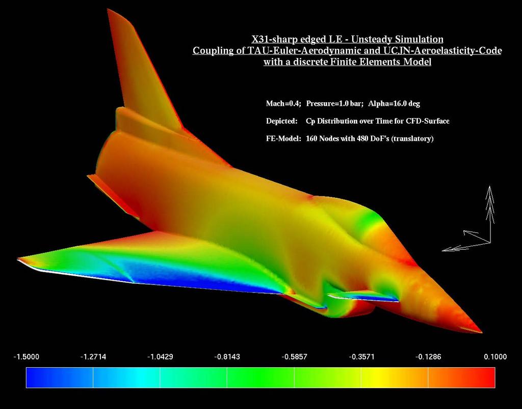
22 FE-modell of X-31-wind tunel model generic CSM-model for large deformations geometry based on CFD surface data model consists of shell elements (CQUAD4 und TRIA3) model consists of 279 nodes and 312 elements CFD-surface mit surface points, 9.6 million elements, 1.7 million points FE-model with 819 degrees of freedom
 and deformations at wing")
23 X-31: half-model with sharp leading edge α=16.0 ; Mach=0.4; t= s; p= N/m² Displacement vectors on finite element model (left) and deformations at wing tip and canard tip over the time (rechts)
24
25 Conclusion & outlook The parallel TAU deformation method has been described and demonstrated, it is robust for many applications. can be applied on the same grid partitions distributed over the processes for the TAU preprocessor/solver and adaptation, without re-partitioning and redistribution of data. the memory requirements scale with the number of processes, thus it is no memory bottleneck for large scale applications. the time requirements of the parallel deformation for static aeroelastic simulations are negligible. for dynamic aeroelastic simulations the runtime requirements of the parallel deformation can become relevant (> 25% of solver runtime). Improvements or alternative methods might have to be considered, especially for massive parallel applications.
26 end
TAU User Meeting, Göttingen,
 TAU User Meeting, Göttingen, 22.9.2005 Fluid-Structure-Coupling Using the TAU Code: Developments and Applications at the DLR Institute of Aeroelasticity Wolf Krüger DLR Institute of Aeroelasticity Fluid-Structure-Coupling
An advanced RBF Morph application: coupled CFD-CSM Aeroelastic Analysis of a Full Aircraft Model and Comparison to Experimental Data
 An advanced RBF Morph application: coupled CFD-CSM Aeroelastic Analysis of a Full Aircraft Model and Comparison to Experimental Data Dr. Marco Evangelos Biancolini Tor Vergata University, Rome, Italy Dr.
Numerical Simulations of Fluid-Structure Interaction Problems using MpCCI
 Numerical Simulations of Fluid-Structure Interaction Problems using MpCCI François Thirifay and Philippe Geuzaine CENAERO, Avenue Jean Mermoz 30, B-6041 Gosselies, Belgium Abstract. This paper reports
Numerical Methods in Aerodynamics. Fluid Structure Interaction. Lecture 4: Fluid Structure Interaction
 Fluid Structure Interaction Niels N. Sørensen Professor MSO, Ph.D. Department of Civil Engineering, Alborg University & Wind Energy Department, Risø National Laboratory Technical University of Denmark
39th AIAA Aerospace Sciences Meeting and Exhibit January 8 11, 2001/Reno, NV
 AIAA 1 717 Static Aero-elastic Computation with a Coupled CFD and CSD Method J. Cai, F. Liu Department of Mechanical and Aerospace Engineering University of California, Irvine, CA 92697-3975 H.M. Tsai,
Accurate and Efficient Turbomachinery Simulation. Chad Custer, PhD Turbomachinery Technical Specialist
 Accurate and Efficient Turbomachinery Simulation Chad Custer, PhD Turbomachinery Technical Specialist Outline Turbomachinery simulation advantages Axial fan optimization Description of design objectives
THE EFFECTS OF THE PLANFORM SHAPE ON DRAG POLAR CURVES OF WINGS: FLUID-STRUCTURE INTERACTION ANALYSES RESULTS
 March 18-20, 2013 THE EFFECTS OF THE PLANFORM SHAPE ON DRAG POLAR CURVES OF WINGS: FLUID-STRUCTURE INTERACTION ANALYSES RESULTS Authors: M.R. Chiarelli, M. Ciabattari, M. Cagnoni, G. Lombardi Speaker:
Validation of an Unstructured Overset Mesh Method for CFD Analysis of Store Separation D. Snyder presented by R. Fitzsimmons
 Validation of an Unstructured Overset Mesh Method for CFD Analysis of Store Separation D. Snyder presented by R. Fitzsimmons Stores Separation Introduction Flight Test Expensive, high-risk, sometimes catastrophic
FAR-Wake Workshop, Marseille, May 2008
 Wake Vortices generated by an Aircraft Fuselage : Comparison of Wind Tunnel Measurements on the TAK Model with RANS and RANS-LES Simulations T. Louagie, L. Georges & P. Geuzaine Cenaero CFD-Multiphysics
Aeroelasticity in MSC.Nastran
 Aeroelasticity in MSC.Nastran Hybrid Static Aeroelasticity new capabilities - CFD data management Presented By: Fausto Gill Di Vincenzo 04-06-2012 Hybrid Static Aeroelastic Solution with CFD data MSC.Nastran
Recent developments for the multigrid scheme of the DLR TAU-Code
 www.dlr.de Chart 1 > 21st NIA CFD Seminar > Axel Schwöppe Recent development s for the multigrid scheme of the DLR TAU-Code > Apr 11, 2013 Recent developments for the multigrid scheme of the DLR TAU-Code
Fluid-Structure Coupling for Aerodynamic Analysis and Design A DLR Perspective
 46th AIAA Aerospace Sciences Meeting and Exhibit 7-10 January 2008, Reno, Nevada AIAA 2008-561 Fluid-Structure Coupling for Aerodynamic Analysis and Design A DLR Perspective R. Heinrich 1 and N. Kroll.
Introduction to ANSYS CFX
 Workshop 03 Fluid flow around the NACA0012 Airfoil 16.0 Release Introduction to ANSYS CFX 2015 ANSYS, Inc. March 13, 2015 1 Release 16.0 Workshop Description: The flow simulated is an external aerodynamics
STABILITY ANALYSIS IN THE TIME-DOMAIN APPLIED TO ADAPTIVE TRANSPORT-AIRCRAFT WINGS
 ICAS 22 CONGRESS STABILITY ANALYSIS IN THE TIME-DOMAIN APPLIED TO ADAPTIVE TRANSPORT-AIRCRAFT WINGS Wolfgang Send and Ralph Voss Institute of Aeroelasticity, German Aerospace Center (DLR) 3773 Göttingen,
Application of Wray-Agarwal Turbulence Model for Accurate Numerical Simulation of Flow Past a Three-Dimensional Wing-body
 Washington University in St. Louis Washington University Open Scholarship Mechanical Engineering and Materials Science Independent Study Mechanical Engineering & Materials Science 4-28-2016 Application
UNSTEADY TAU AND ROM FOR FLUTTER COMPUTATIONS OF TRANSPORT AIRCRAFT. Reik Thormann, Ralph Voß. Folie 1
 UNSTEADY TAU AND ROM FOR FLUTTER COMPUTATIONS OF TRANSPORT AIRCRAFT Reik Thormann, Ralph Voß Folie 1 Standardfoliensatz >01.03.2007 Outline Motivation Synthetic Mode Correction (SMC) Linearized CFD Method
Constrained Aero-elastic Multi-Point Optimization Using the Coupled Adjoint Approach
 www.dlr.de Chart 1 Aero-elastic Multi-point Optimization, M.Abu-Zurayk, MUSAF II, 20.09.2013 Constrained Aero-elastic Multi-Point Optimization Using the Coupled Adjoint Approach M. Abu-Zurayk MUSAF II
MSC Software Aeroelastic Tools. Mike Coleman and Fausto Gill di Vincenzo
 MSC Software Aeroelastic Tools Mike Coleman and Fausto Gill di Vincenzo MSC Software Confidential 2 MSC Software Confidential 3 MSC Software Confidential 4 MSC Software Confidential 5 MSC Flightloads An
CFD studies of a 10 MW turbine equipped with trailing edge flaps
 CFD studies of a 10 MW turbine equipped with trailing edge flaps 10th EAWE PhD Seminar on Wind Energy in Europe 28-31 October 2014, Orléans, France Dipl.-Ing. Eva Jost e.jost@iag.uni-stuttgart.de Overview
Numerical Investigation of Transonic Shock Oscillations on Stationary Aerofoils
 Numerical Investigation of Transonic Shock Oscillations on Stationary Aerofoils A. Soda, T. Knopp, K. Weinman German Aerospace Center DLR, Göttingen/Germany Symposium on Hybrid RANS-LES Methods Stockholm/Sweden,
ANSYS Fluid Structure Interaction for Thermal Management and Aeroelasticity
 ANSYS Fluid Structure Interaction for Thermal Management and Aeroelasticity Phil Stopford Duxford Air Museum 11th May 2011 2011 2010 ANSYS, Inc. All rights reserved. 1 ANSYS, Inc. Proprietary Fluid Structure
1.2 Numerical Solutions of Flow Problems
 1.2 Numerical Solutions of Flow Problems DIFFERENTIAL EQUATIONS OF MOTION FOR A SIMPLIFIED FLOW PROBLEM Continuity equation for incompressible flow: 0 Momentum (Navier-Stokes) equations for a Newtonian
Usage of CFX for Aeronautical Simulations
 Usage of CFX for Aeronautical Simulations Florian Menter Development Manager Scientific Coordination ANSYS Germany GmbH Overview Elements of CFD Technology for aeronautical simulations: Grid generation
Fluid structure interaction analysis: vortex shedding induced vibrations
 Fluid structure interaction analysis: vortex shedding induced vibrations N. Di Domenico, M. E. * University of Rome «Tor Vergata», Department of Enterprise Engineering «Mario Lucertini» A. Wade, T. Berg,
Keisuke Sawada. Department of Aerospace Engineering Tohoku University
 March 29th, 213 : Next Generation Aircraft Workshop at Washington University Numerical Study of Wing Deformation Effect in Wind-Tunnel Testing Keisuke Sawada Department of Aerospace Engineering Tohoku
State of the art at DLR in solving aerodynamic shape optimization problems using the discrete viscous adjoint method
 DLR - German Aerospace Center State of the art at DLR in solving aerodynamic shape optimization problems using the discrete viscous adjoint method J. Brezillon, C. Ilic, M. Abu-Zurayk, F. Ma, M. Widhalm
Three-dimensional numerical simulations of flapping wings at low Reynolds numbers
 Three-dimensional numerical simulations of flapping wings at low Reynolds numbers OpenFOAM Workshop, Zagreb Frank Bos, Bas van Oudheusden, Hester Bijl 7-9 June 2007 1/22 Delft University of Technology
Digital-X. Towards Virtual Aircraft Design and Testing based on High-Fidelity Methods - Recent Developments at DLR -
 Digital-X Towards Virtual Aircraft Design and Testing based on High-Fidelity Methods - Recent Developments at DLR - O. Brodersen, C.-C. Rossow, N. Kroll DLR Institute of Aerodynamics and Flow Technology
An advanced RBF Morph application: coupled CFD-CSM Aeroelastic Analysis of a Full Aircraft Model and Comparison to Experimental Data
 An advanced RBF Morph application: coupled CFD-CSM Aeroelastic Analysis of a Full Aircraft Model and Comparison to Experimental Data Ubaldo Cella 1 Piaggio Aero Industries, Naples, Italy Marco Evangelos
High-Lift Aerodynamics: STAR-CCM+ Applied to AIAA HiLiftWS1 D. Snyder
 High-Lift Aerodynamics: STAR-CCM+ Applied to AIAA HiLiftWS1 D. Snyder Aerospace Application Areas Aerodynamics Subsonic through Hypersonic Aeroacoustics Store release & weapons bay analysis High lift devices
Multigrid Algorithms for Three-Dimensional RANS Calculations - The SUmb Solver
 Multigrid Algorithms for Three-Dimensional RANS Calculations - The SUmb Solver Juan J. Alonso Department of Aeronautics & Astronautics Stanford University CME342 Lecture 14 May 26, 2014 Outline Non-linear
Explicit Mesh Deformation Using Inverse Distance Weighting Interpolation
 19th AIAA Computational Fluid Dynamics 22-25 June 2009, San Antonio, Texas AIAA 2009-3996 Explicit Mesh Deformation Using Inverse Distance Weighting Interpolation Jeroen A.S. Witteveen, Hester Bijl Faculty
Second Symposium on Hybrid RANS-LES Methods, 17/18 June 2007
 1 Zonal-Detached Eddy Simulation of Transonic Buffet on a Civil Aircraft Type Configuration V.BRUNET and S.DECK Applied Aerodynamics Department The Buffet Phenomenon Aircraft in transonic conditions Self-sustained
MSC/NASTRAN FLUTTER ANALYSES OF T-TAILS INCLUDING HORIZONTAL STABILIZER STATIC LIFT EFFECTS AND T-TAIL TRANSONIC DIP
 MSC/NASTRAN FLUTTER ANALYSES OF T-TAILS INCLUDING HORIZONTAL STABILIZER STATIC LIFT EFFECTS AND T-TAIL TRANSONIC DIP by Emil Suciu* Gulfstream Aerospace Corporation Savannah, Georgia U.S.A. Presented at
2.7 Cloth Animation. Jacobs University Visualization and Computer Graphics Lab : Advanced Graphics - Chapter 2 123
 2.7 Cloth Animation 320491: Advanced Graphics - Chapter 2 123 Example: Cloth draping Image Michael Kass 320491: Advanced Graphics - Chapter 2 124 Cloth using mass-spring model Network of masses and springs
Status of Gradient-based Airframe MDO at DLR The VicToria Project
 DLR.de Chart 1 Status of Gradient-based Airframe MDO at DLR The VicToria Project M. Abu-Zurayk, C. Ilic, A. Merle, A. Stück, S. Keye, A. Rempke (Institute of Aerodynamics and Flow Technology) T. Klimmek,
Geometry Parameterization for Shape Optimization. Arno Ronzheimer
 Geometry Parameterization for Shape Optimization Arno Ronzheimer Dokumentname > 11.07.2006 23.11.2004 Overview Motivation for Geometry Parameterization Classification of Methods Criteria for Choosing a
Adjoint-Based Sensitivity Analysis for Computational Fluid Dynamics
 Adjoint-Based Sensitivity Analysis for Computational Fluid Dynamics Dimitri J. Mavriplis Max Castagne Professor Department of Mechanical Engineering University of Wyoming Laramie, WY USA Motivation Computational
First TAU Theory and Praxis Training From CAD to Grid
 First TAU Theory and Praxis Training From CAD to Grid S. Melber-Wilkending First TAU Theory and Praxis Training From CAD to Grid or How to use the Centaur-Grid-Generator S. Melber-Wilkending Outline Introduction
Efficient Aero-Acoustic Simulation of the HART II Rotor with the Compact Pade Scheme Gunther Wilke DLR AS-HEL Sept 6th nd ERF Lille, France
 www.dlr.de Chart 1 Efficient Aero-Acoustic Simulation of the HART II Rotor with the Compact Pade Scheme Gunther Wilke DLR AS-HEL Sept 6th 2016 42nd ERF Lille, France www.dlr.de Chart 2 Overview - Motivation
Development of an Integrated Computational Simulation Method for Fluid Driven Structure Movement and Acoustics
 Development of an Integrated Computational Simulation Method for Fluid Driven Structure Movement and Acoustics I. Pantle Fachgebiet Strömungsmaschinen Karlsruher Institut für Technologie KIT Motivation
Challenges in Boundary- Layer Stability Analysis Based On Unstructured Grid Solutions
 Challenges in Boundary- Layer Stability Analysis Based On Unstructured Grid Solutions Wei Liao National Institute of Aerospace, Hampton, Virginia Collaborators: Mujeeb R. Malik, Elizabeth M. Lee- Rausch,
CFD Best Practice Guidelines: A process to understand CFD results and establish Simulation versus Reality
 CFD Best Practice Guidelines: A process to understand CFD results and establish Simulation versus Reality Judd Kaiser ANSYS Inc. judd.kaiser@ansys.com 2005 ANSYS, Inc. 1 ANSYS, Inc. Proprietary Overview
Revised Sheet Metal Simulation, J.E. Akin, Rice University
 Revised Sheet Metal Simulation, J.E. Akin, Rice University A SolidWorks simulation tutorial is just intended to illustrate where to find various icons that you would need in a real engineering analysis.
NEW METHOD FOR MESH MOVING BASED ON RADIAL BASIS FUNCTION INTERPOLATION
 European Conference on Computational Fluid Dynamics ECCOMAS CFD 2006 P. Wesseling, E. Oñate and J. Périaux (Eds) c TU Delft, The Netherlands, 2006 NEW METHOD FOR MESH MOVING BASED ON RADIAL BASIS FUNCTION
computational Fluid Dynamics - Prof. V. Esfahanian
 Three boards categories: Experimental Theoretical Computational Crucial to know all three: Each has their advantages and disadvantages. Require validation and verification. School of Mechanical Engineering
Marine Hydrodynamics Solver in OpenFOAM
 Marine Hydrodynamics Solver in OpenFOAM p. 1/14 Marine Hydrodynamics Solver in OpenFOAM Hrvoje Jasak and Henrik Rusche h.jasak@wikki.co.uk, h.rusche@wikki.co.uk Wikki, United Kingdom and Germany 4 December
A Scalable GPU-Based Compressible Fluid Flow Solver for Unstructured Grids
 A Scalable GPU-Based Compressible Fluid Flow Solver for Unstructured Grids Patrice Castonguay and Antony Jameson Aerospace Computing Lab, Stanford University GTC Asia, Beijing, China December 15 th, 2011
Missile External Aerodynamics Using Star-CCM+ Star European Conference 03/22-23/2011
 Missile External Aerodynamics Using Star-CCM+ Star European Conference 03/22-23/2011 StarCCM_StarEurope_2011 4/6/11 1 Overview 2 Role of CFD in Aerodynamic Analyses Classical aerodynamics / Semi-Empirical
Prediction of the Unsteady Behavior of Maneuvering Aircraft by CFD Aerodynamic, Flight-Mechanic and Aeroelastic Coupling
 CFD Aerodynamic, Flight-Mechanic and Aeroelastic Coupling Andreas Schütte, Gunnar Einarsson, Axel Raichle, Britta Schöning Deutsches Zentrum für Luft- und Raumfahrt e.v. in der Helmholtz-Gemeinschaft,
Simulating Sinkage & Trim for Planing Boat Hulls. A Fluent Dynamic Mesh 6DOF Tutorial
 Simulating Sinkage & Trim for Planing Boat Hulls A Fluent Dynamic Mesh 6DOF Tutorial 1 Introduction Workshop Description This workshop describes how to perform a transient 2DOF simulation of a planing
Contribution to GMGW-1
 Contribution to GMGW-1 Vivek Ahuja, Shaunak Pai, John Wilson, Rajesh Kumar, Michael Stubert Inc. (003) Restricted Siemens AG 2017 Realize innovation. Summary of meshes generated Star-CCM+ Geometry Core
Morphing high lift structures: Smart leading edge device and smart single slotted flap Hans Peter Monner, Johannes Riemenschneider Madrid, 30 th
 Morphing high lift structures: Smart leading edge device and smart single slotted flap Hans Peter Monner, Johannes Riemenschneider Madrid, 30 th March 2011 Outline Background Project overview Selected
Hydro-elastic analysis of a propeller using CFD and FEM co-simulation
 Fifth International Symposium on Marine Propulsors smp 17, Espoo, Finland, June 2017 Hydro-elastic analysis of a propeller using CFD and FEM co-simulation Vesa Nieminen 1 1 VTT Technical Research Centre
Implementation of an integrated efficient parallel multiblock Flow solver
 Implementation of an integrated efficient parallel multiblock Flow solver Thomas Bönisch, Panagiotis Adamidis and Roland Rühle adamidis@hlrs.de Outline Introduction to URANUS Why using Multiblock meshes
Multigrid Solvers in CFD. David Emerson. Scientific Computing Department STFC Daresbury Laboratory Daresbury, Warrington, WA4 4AD, UK
 Multigrid Solvers in CFD David Emerson Scientific Computing Department STFC Daresbury Laboratory Daresbury, Warrington, WA4 4AD, UK david.emerson@stfc.ac.uk 1 Outline Multigrid: general comments Incompressible
NUMERICAL 3D TRANSONIC FLOW SIMULATION OVER A WING
 Review of the Air Force Academy No.3 (35)/2017 NUMERICAL 3D TRANSONIC FLOW SIMULATION OVER A WING Cvetelina VELKOVA Department of Technical Mechanics, Naval Academy Nikola Vaptsarov,Varna, Bulgaria (cvetelina.velkova1985@gmail.com)
Your Home for Advanced Aerodynamic/ Aeroelastic/Aeroservoelastic/Computer Aided Engineering Software Products and Services
 Your Home for Advanced Aerodynamic/ Aeroelastic/Aeroservoelastic/Computer Aided Engineering Software Products and Services About ZONA ZONA Technology, Inc. (ZONA) is a privately held company that was founded
GEOMETRY MODELING & GRID GENERATION
 GEOMETRY MODELING & GRID GENERATION Dr.D.Prakash Senior Assistant Professor School of Mechanical Engineering SASTRA University, Thanjavur OBJECTIVE The objectives of this discussion are to relate experiences
Best Practices Workshop: Overset Meshing
 Best Practices Workshop: Overset Meshing Overview Introduction to Overset Meshes Range of Application Workflow Demonstrations and Best Practices What are Overset Meshes? Overset meshes are also known as
UNSTEADY RANS BASED IMPULSE RESPONSE STUDIES OF AGARD WING FOR AEROELASTIC AND FLUTTER ANALYSIS
 Symposium on Applied Aerodynamics and Design of Aerospace Vehicles (SAROD 2) November 68, 2, Bangalore, India UNSTEADY RANS BASED IMPULSE RESPONSE STUDIES OF AGARD WING FOR AEROELASTIC AND FLUTTER ANALYSIS
Handling Parallelisation in OpenFOAM
 Handling Parallelisation in OpenFOAM Hrvoje Jasak hrvoje.jasak@fsb.hr Faculty of Mechanical Engineering and Naval Architecture University of Zagreb, Croatia Handling Parallelisation in OpenFOAM p. 1 Parallelisation
Advances in Turbomachinery Simulation Fred Mendonça and material prepared by Chad Custer, Turbomachinery Technology Specialist
 Advances in Turbomachinery Simulation Fred Mendonça and material prepared by Chad Custer, Turbomachinery Technology Specialist Usage From Across the Industry Outline Key Application Objectives Conjugate
MAJOR IMPROVEMENTS IN STORES SEPARATION ANALYSIS USING FLEXIBLE AIRCRAFT
 27 TH INTERNATIONAL CONGRESS OF THE AERONAUTICAL SCIENCES MAJOR IMPROVEMENTS IN STORES SEPARATION ANALYSIS USING FLEXIBLE AIRCRAFT Hans Wallenius, Anders Lindberg Saab AB, SE-581 88 Linkoping, Sweden Keywords:
OzenCloud Case Studies
 OzenCloud Case Studies Case Studies, April 20, 2015 ANSYS in the Cloud Case Studies: Aerodynamics & fluttering study on an aircraft wing using fluid structure interaction 1 Powered by UberCloud http://www.theubercloud.com
Finite Element Method. Chapter 7. Practical considerations in FEM modeling
 Finite Element Method Chapter 7 Practical considerations in FEM modeling Finite Element Modeling General Consideration The following are some of the difficult tasks (or decisions) that face the engineer
Chapter 7 Practical Considerations in Modeling. Chapter 7 Practical Considerations in Modeling
 CIVL 7/8117 1/43 Chapter 7 Learning Objectives To present concepts that should be considered when modeling for a situation by the finite element method, such as aspect ratio, symmetry, natural subdivisions,
THE INFLUENCE OF MESH CHARACTERISTICS ON OPENFOAM SIMULATIONS OF THE DRIVAER MODEL
 6 th BETA CAE International Conference THE INFLUENCE OF MESH CHARACTERISTICS ON OPENFOAM SIMULATIONS OF THE DRIVAER MODEL Grigoris Fotiadis *, Vangelis Skaperdas, Aristotelis Iordanidis BETA CAE Systems
Prediction of Helicopter Blade- Vortex Interaction Noise using Motion Data from Experiment
 Prediction of Helicopter Blade- Vortex Interaction Noise using Motion Data from Experiment Yoshinobu Inada, Choongmo Yang, and Takashi Aoyama Computational Science Research Group (CSRG) Institute of Aerospace
DNV GL s 16th Technology Week
 OIL & GAS DNV GL s 16th Technology Week Advanced Simulation for Offshore Application: Application of CFD for Computing VIM of Floating Structures 1 SAFER, SMARTER, GREENER OUTLINE Introduction Elements
Coupled Simulation of Flow and Body Motion Using Overset Grids. Eberhard Schreck & Milovan Perić
 Coupled Simulation of Flow and Body Motion Using Overset Grids Eberhard Schreck & Milovan Perić Contents Dynamic Fluid-Body Interaction (DFBI) model in STAR-CCM+ Overset grids method in STAR-CCM+ Advantages
AIAA APPLICATION OF THE TRANSPIRATION METHOD FOR AEROSERVOELASTIC PREDICTION USING CFD
 1 AIAA-98-271 APPLICATION OF THE TRANSPIRATION METHOD FOR AEROSERVOELASTIC PREDICTION USING CFD Abstract Research presented in this paper illustrates the implementation of the transpiration boundary condition
NASA Rotor 67 Validation Studies
 NASA Rotor 67 Validation Studies ADS CFD is used to predict and analyze the performance of the first stage rotor (NASA Rotor 67) of a two stage transonic fan designed and tested at the NASA Glenn center
Optimate CFD Evaluation Optimate Glider Optimization Case
 Optimate CFD Evaluation Optimate Glider Optimization Case Authors: Nathan Richardson LMMFC CFD Lead 1 Purpose For design optimization, the gold standard would be to put in requirements and have algorithm
The Use of Python Scripts in TAU. Thomas Gerhold. Folie 1 > TAU -Python scripting capability. 22/23t September 20055
 The Use of Python Scripts in TAU Thomas Gerhold Folie 1 > TAU -Python scripting capability 22/23t September 20055 Overview Background Idea Perspectives Usage of python scripts Scripting examples & capabilities
Improvements to a Newton-Krylov Adjoint Algorithm for Aerodynamic Optimization
 Improvements to a Newton-Krylov Adjoint Algorithm for Aerodynamic Optimization David W. Zingg, Timothy M. Leung, Laslo Diosady, Anh H. Truong, and Samy Elias Institute for Aerospace Studies, University
NUMERICAL SIMULATION OF THE FREE PITCH OSCILLATION FOR A RE-ENTRY VEHICLE IN TRANSONIC WIND TUNNEL FLOW
 NUMERICAL SIMULATION OF THE FREE PITCH OSCILLATION FOR A RE-ENTRY VEHICLE IN TRANSONIC WIND TUNNEL FLOW Bodo Reimann German Aerospace Center (DLR), Institute of Aerodynamics and Flow Technology, Lilienthalplatz
German Aerospace Center, Institute of Aerodynamics and Flow Technology, Numerical Methods
 Automatische Transitionsvorhersage im DLR TAU Code Status der Entwicklung und Validierung Automatic Transition Prediction in the DLR TAU Code - Current Status of Development and Validation Andreas Krumbein
T6: Position-Based Simulation Methods in Computer Graphics. Jan Bender Miles Macklin Matthias Müller
 T6: Position-Based Simulation Methods in Computer Graphics Jan Bender Miles Macklin Matthias Müller Jan Bender Organizer Professor at the Visual Computing Institute at Aachen University Research topics
Improved Unsteady Aerodynamic Influence Coefficients for Dynamic Aeroelastic Response
 Improved Unsteady Aerodynamic Influence Coefficients for Dynamic Aeroelastic Response Quinn Murphy Department of Mechanical Engineering McGill University Montréal, Canada December 212 A thesis submitted
Partitioned strongly coupled Fluid-Structure Interaction
 Partitioned strongly coupled Fluid-Structure Interaction 7 th OpenFOAM Workshop Darmstadt, Germany Manuel Kosel * 1 and Ulrich Heck 2 1 Center for Computational Engineering Science, RWTH Aachen University,
ABOUT THE GENERATION OF UNSTRUCTURED MESH FAMILIES FOR GRID CONVERGENCE ASSESSMENT BY MIXED MESHES
 VI International Conference on Adaptive Modeling and Simulation ADMOS 2013 J. P. Moitinho de Almeida, P. Díez, C. Tiago and N. Parés (Eds) ABOUT THE GENERATION OF UNSTRUCTURED MESH FAMILIES FOR GRID CONVERGENCE
A DRAG PREDICTION VALIDATION STUDY FOR AIRCRAFT AERODYNAMIC ANALYSIS
 A DRAG PREDICTION VALIDATION STUDY FOR AIRCRAFT AERODYNAMIC ANALYSIS Akio OCHI, Eiji SHIMA Kawasaki Heavy Industries, ltd Keywords: CFD, Drag prediction, Validation Abstract A CFD drag prediction validation
Studies of the Continuous and Discrete Adjoint Approaches to Viscous Automatic Aerodynamic Shape Optimization
 Studies of the Continuous and Discrete Adjoint Approaches to Viscous Automatic Aerodynamic Shape Optimization Siva Nadarajah Antony Jameson Stanford University 15th AIAA Computational Fluid Dynamics Conference
Figure 30. Degrees of freedom of flat shell elements
 Shell finite elements There are three types of shell finite element; 1) flat elements, 2) elements based on the Sanders-Koiter equations and 3) elements based on reduction of a solid element. Flat elements
GRID PATTERN EFFECTS ON AERODYNAMIC CHARACTERISTICS OF GRID FINS
 24 TH INTERNATIONAL CONGRESS OF THE AERONAUTICAL SCIENCES GRID PATTERN EFFECTS ON AERODYNAMIC CHARACTERISTICS OF GRID FINS Fumiya Hiroshima, Kaoru Tatsumi* *Mitsubishi Electric Corporation, Kamakura Works,
A STUDY ON THE UNSTEADY AERODYNAMICS OF PROJECTILES IN OVERTAKING BLAST FLOWFIELDS
 HEFAT2012 9 th International Conference on Heat Transfer, Fluid Mechanics and Thermodynamics 16 18 July 2012 Malta A STUDY ON THE UNSTEADY AERODYNAMICS OF PROJECTILES IN OVERTAKING BLAST FLOWFIELDS Muthukumaran.C.K.
LS-DYNA s Linear Solver Development Phase 2: Linear Solution Sequence
 LS-DYNA s Linear Solver Development Phase 2: Linear Solution Sequence Allen T. Li 1, Zhe Cui 2, Yun Huang 2 1 Ford Motor Company 2 Livermore Software Technology Corporation Abstract This paper continues
Coupling of STAR-CCM+ to Other Theoretical or Numerical Solutions. Milovan Perić
 Coupling of STAR-CCM+ to Other Theoretical or Numerical Solutions Milovan Perić Contents The need to couple STAR-CCM+ with other theoretical or numerical solutions Coupling approaches: surface and volume
Funded by the European Union INRIA. AEROGUST Workshop 27 th - 28 th April 2017, University of Liverpool. Presented by Andrea Ferrero and Angelo Iollo
 INRIA AEROGUST Workshop 27 th - 28 th April 2017, University of Liverpool Presented by Andrea Ferrero and Angelo Iollo Aero-elastic study of a wind turbine subjected to a gust Development of high-fidelity
Introduction to Multigrid and its Parallelization
 Introduction to Multigrid and its Parallelization! Thomas D. Economon Lecture 14a May 28, 2014 Announcements 2 HW 1 & 2 have been returned. Any questions? Final projects are due June 11, 5 pm. If you are
Mesh Morphing and the Adjoint Solver in ANSYS R14.0. Simon Pereira Laz Foley
 Mesh Morphing and the Adjoint Solver in ANSYS R14.0 Simon Pereira Laz Foley 1 Agenda Fluent Morphing-Optimization Feature RBF Morph with ANSYS DesignXplorer Adjoint Solver What does an adjoint solver do,
smooth coefficients H. Köstler, U. Rüde
 A robust multigrid solver for the optical flow problem with non- smooth coefficients H. Köstler, U. Rüde Overview Optical Flow Problem Data term and various regularizers A Robust Multigrid Solver Galerkin
Lecture 7: Introduction to HFSS-IE
 Lecture 7: Introduction to HFSS-IE 2015.0 Release ANSYS HFSS for Antenna Design 1 2015 ANSYS, Inc. HFSS-IE: Integral Equation Solver Introduction HFSS-IE: Technology An Integral Equation solver technology
Driven Cavity Example
 BMAppendixI.qxd 11/14/12 6:55 PM Page I-1 I CFD Driven Cavity Example I.1 Problem One of the classic benchmarks in CFD is the driven cavity problem. Consider steady, incompressible, viscous flow in a square
RBF Morph An Add-on Module for Mesh Morphing in ANSYS Fluent
 RBF Morph An Add-on Module for Mesh Morphing in ANSYS Fluent Gilles Eggenspieler Senior Product Manager 1 Morphing & Smoothing A mesh morpher is a tool capable of performing mesh modifications in order
Single and multi-point aerodynamic optimizations of a supersonic transport aircraft using strategies involving adjoint equations and genetic algorithm
 Single and multi-point aerodynamic optimizations of a supersonic transport aircraft using strategies involving adjoint equations and genetic algorithm Prepared by : G. Carrier (ONERA, Applied Aerodynamics/Civil
AEROELASTICITY IN AXIAL FLOW TURBOMACHINES
 von Karman Institute for Fluid Dynamics Lecture Series Programme 1998-99 AEROELASTICITY IN AXIAL FLOW TURBOMACHINES May 3-7, 1999 Rhode-Saint- Genèse Belgium CASE STUDIES IN TURBOMACHINERY AEROELASTICITY
Coupled Analysis of FSI
 Coupled Analysis of FSI Qin Yin Fan Oct. 11, 2008 Important Key Words Fluid Structure Interface = FSI Computational Fluid Dynamics = CFD Pressure Displacement Analysis = PDA Thermal Stress Analysis = TSA
Shape optimisation using breakthrough technologies
 Shape optimisation using breakthrough technologies Compiled by Mike Slack Ansys Technical Services 2010 ANSYS, Inc. All rights reserved. 1 ANSYS, Inc. Proprietary Introduction Shape optimisation technologies