3DView Installation and Operation
|
|
|
- Benjamin Bishop
- 5 years ago
- Views:
Transcription
1 The following notes are intended as a guide to the installation and operation of the 3DView Volume Rendering Application. As this software is still under development, some of the features and screenshots may differ from those described. NOTE BEFORE USING 3DVIEW, PLEASE REFER TO THE LICENSE AND COPYRIGHT NOTICES INSTALLED IN THE APPLICATION FOLDER AND REPRODUCED AT THE END OF THIS DOCUMENT. Acknowledgements 3DView has been developed as a joint initiative between RMR Systems Limited, represented byroger Rowland, and Dr. Rudy Lapeer from the School of Computing Sciences at the University of East Anglia. Installation Rudy J. Lapeer, PhD Roger S. Rowland MSc MBCS CITP MIAP School of Computing Sciences RMR Systems Limited University of East Anglia (UEA) Cardinal House Norwich NR4 7TJ 46 St Nicholas Street England Ipswich IP1 1TT Tel. +44 (0) / 2692 (Lab) Tel. +44 (0) Mob Mob rjal@sys.uea.ac.uk roger.rowland@rmrsystems.co.uk To install the 3DView executable and sample data, run the SETUP.EXE program contained in the CD or downloaded distribution. Follow the instructions on screen. Although this application will run on most modern PC hardware, the following configuration is recommended for best performance: Windows 2000 or Windows XP Pentium IV Processor 2.0GHz or faster 512Mb RAM ATI Radeon 9000 or above, or Nvidia GeForce 4 with 128Mb RAM Getting Started After installation, a shortcut to 3DView will be present on the Start/Programs menu. Use this to launch the application. Most of the applications features are driven from the menu or toolbar or by using the mouse over the working area of the display. The toolbar allows easy selection of the following options: Selects fly-through mode Interactive cut-plane manipulation (6 planes) Multi-Planar Reformatting view (MPR) Reset display to default position and orientation. Also removes any cut-planes Maximum Intensity Projection view (MIP) Select normal alpha blended volume view Open a file for display. 3DView supports the following file formats: *.3dv Native format files *.raw Raw data (8 or 16 bit) *.dcm DICOM Images *.* DICOM Series
2 Launch the application and use the toolbar button or menu option (File/Open) to open the sample data file HEAD256.3DV. A screen similar to the following should be shown: The panel on the left shows three planar views of the volume in preview mode. A red cross shows the point of interest in MPR view or the camera position/orientation in fly-through mode. In all views, the point of interest may be selected by left-clicking and/or dragging with the mouse over any of the three planar images. The individual slider bars may also be used to scroll through the slices. The three views will remain synchronised. The main window shows the default volume view. The image may be rotated by left-clicking and dragging on the image itself. By dragging and releasing the mouse, it is possible to initiate a spinning of the displayed object. A single click with the left mouse button will stop the spin. The Reset button on the toolbar may also be used. There are four thumbwheel controls in the border of the main window. Left-click and drag over these controls to rotate the view about the X, Y or Z axis, or to zoom in or out as required. Again, the Reset option on the toolbar will return to the default view as shown above. Maximum Intensity Projection (MIP) Clicking this button on the toolbar will switch the display to MIP mode. In this view, the blending function is altered so that the voxels with the maximum intensity through the line of view are mapped to the display. This results in the characteristic semi-transparent view, used primarily with MR images that have a well defined internal structure. For an example of this display, refer to the Stereo View section later in this document. Click again on the VOL button on the toolbar to return to the default view.
3 Multi-Planar Reformatting (MPR) The MPR features available in 3DView are at present fairly basic. To demonstrate how this works, load the sample data as described above, then click on the MPR button in the toolbar. A display similar to that below will be shown. The volume data is displayed as an intersection of three planes (in the x, y and z orientations). The relevant slice for each plane is projected onto the front and back of each plane. The planes may be moved either by clicking and dragging with the left mouse button over any of the three planar preview images in the left hand panel of the display, or by clicking and dragging with the right mouse button over the image in the main display: The above screenshot shows the latter method. Simply right-click on the surface of the plane you wish to move (use left-click/drag to rotate the view first if necessary). With the right mouse button held down, the selected plane will be highlighted in red as shown. Drag in the direction of the corner indicators to adjust the position of the selected plane. The planar preview images will be automatically synchronised with this view. In MPR view, the rotation and zoom thumbwheels operate as normal. Interactive Cut-Planes At the moment, six fixed-orientation cut planes are available to allow a sub-volume to be isolated from the loaded data. With the sample data loaded, click on the CUT button on the toolbar. The current positions of the six cut planes will be shown outlined in blue (see overleaf).

4 In a similar way to the MPR view, the cut planes are manipulated by using the right mouse button to click and drag over a particular plane. Again, it may be necessary to rotate the volume in order to gain access to the plane you wish to move. The above screenshot shows the sample volume with just one of the cut planes active. To remove the blue borders around the cut planes, click the VOL button on the toolbar to return to the normal view. The cut planes will remain in place until the Reset button is selected. Fly Through The fly-through view places the camera inside the volume, and allows it to be moved so that you can travel inside the data. The display is still rendered as a volume, rather than as a surface mesh, and so the quality of the image will be dependent on the characteristics of the data and the settings of the transfer function (see later). Navigation in fly-through mode is achieved in various ways: The location of the camera may be set by clicking on any of the three planar views in the left hand panel of the display. An arrow will indicate the current view direction of the camera. The camera may also be moved by clicking the mouse over the main display. In this view, the normal rotate/spin operation of the mouse is disabled. Clicking and holding the left mouse over the image will move the camera forward. Clicking and holding the right mouse button will move the camera backward. The camera s view direction may be changed by using the left/right/up/down cursor keys. Note that with large display sizes and/or lower-spec hardware, there may be a delay between pressing a key and the display being updated. This is an area that we are currently developing further and will be improved in subsequent releases.


5 It is advisable to use the Zoom thumbwheel when in fly through mode to produce an acceptable image. By zooming out, a more wide-angle view is obtained, which can aid navigation. The above screenshot shows a view from inside the lung and chest cavity, using data from a CT scan of the thorax. Stereo View 3DView also offers a stereoscopic view. In this view, which is in a separate window, two images of the volume are rendered each from a slightly different position. The stereo view may be shown in anaglyph mode, in which case it is necessary to wear, for example, red/blue anaglyph glasses, or for commercial stereo displays (we use the left and right images may be shown in dual viewports. As with many areas of 3DView, the stereo display is currently under development. At present, it is possible to achieve effective stereo effects by manipulating the focal length and eye separation controls. The screen shot overleaf shows this in action, with a stereo window over a MIP view of an MRI data set. In this view, we use multiple displays for best effect. The stereo window may be dragged to a secondary display (whether a stereo screen or not) and maximised. The volume may be manipulated as normal (spin, zoom etc.) from the main display. In anaglyph mode, it is possible to select the colours used to match the 3D glasses available.
 from the main menu.")
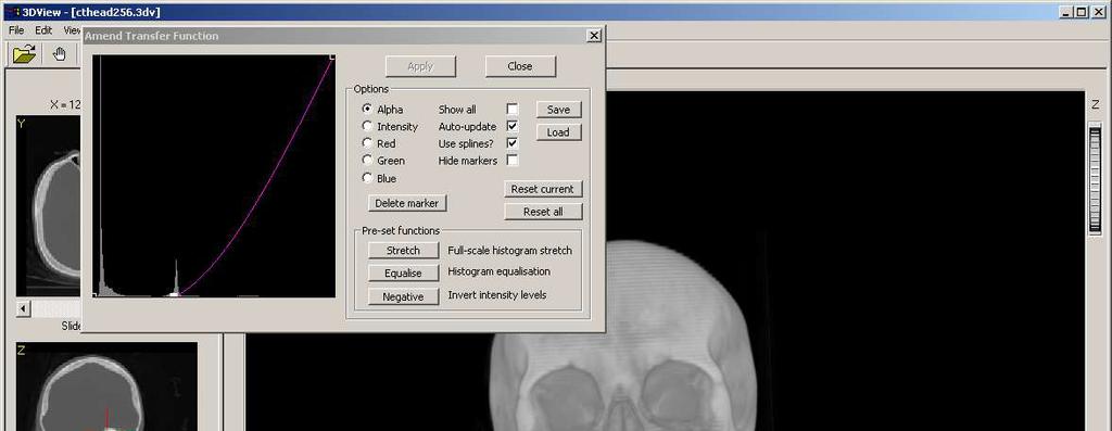
6 Interactive Transfer Function On many modern systems, particularly those using the recommended hardware, it is possible to interactively adjust the transfer function that maps voxel intensities to displayed colours. The transfer function may be amended by selecting (Edit/Transfer function) from the main menu. A histogram display of the intensities present in the volume data will be shown, along with the response curve of each of the available colour channels (red, green, blue, alpha). While it is possible to colourise the data by individual manipulation of the RGB curves, it is more useful to use the alpha channel to vary the transparency of the voxels, and/or the Intensity option (which varies RG & B together). The transfer function is by default implemented as a spline curve although a piecewise linear mapping is possible by selecting the relevant check-box. To add a control point on the graph, simply click with the left mouse at the place where you want the new point. Any existing control points may be selected by left-clicking (the select point will be shown highlighted in white), and then dragging to a new position or deleted by clicking the Delete Marker button on the dialog. The two screenshots overleaf show how the alpha response (transparency) may be varied to produce different views of the same data. In this case, the data set (not supplied) is a CT scan of a skull.

7
 from the main menu. A dialog will be displayed, allowing you to review the volume data in order to select a value for the iso-surface.")
8 Generating a Surface Mesh 3DView uses the Marching Cubes algorithm to produce a 3D mesh representation of an iso-surface from the volume data. To perform surface generation, select (Edit/Generate iso-surface) from the main menu. A dialog will be displayed, allowing you to review the volume data in order to select a value for the iso-surface. The X, Y or Z plane may be selected using the option buttons shown above, and the slices displayed using the scroll bar. Moving the mouse over the image will display the value of the voxel at that position, and left-clicking with the mouse will enter that value in the text box as shown above. At present, this option is only available for 8-bit data sets. Once you have selected a value for the iso-surface, click Process and a mesh of the required surface will be generated. When complete (depending on hardware!), the original volume display will be replaced with a rendering of a 3D mesh (see overleaf). Note that this can produce a very high number of polygons (>600,000 in the above case), and may not operate correctly on lower spec hardware.

9 Note when a surface mesh is displayed, additional toolbar buttons allow selection of solid or wireframe views. Segmentation Segmentation is implemented using a marker-based 3D Watershed algorithm. This allows structures within the data to be isolated from the remainder of the volume. Note this is only available for 8-bit data sets. To perform segmentation, select (Edit/Perform segmentation) from the main menu. A dialog will be displayed, allowing you to review the volume data in order to place markers to control the segmentation. The segmentation dialog is similar to that used for iso-surface generation. It is possible to view the volume as slices through each of the three major axes and to place markers by clicking with the mouse. Click once with the left mouse button on the image to create a marker that is inside the region you wish to segment. The marker will be displayed in green on the image and will also be entered in the topmost of the two list boxes on the dialog. If you place a marker in error, click on the coordinates of the marker in the list box and remove the marker by clicking the delete button. Click once with the right mouse button on the image to create a marker that is outside the region you wish to segment. The marker will be displayed in red on the image and will also be entered in the lower of the two list boxes on the dialog. If you place a marker in error, click on the coordinates of the marker in the list box and remove the marker by clicking the delete button. If, on any particular slice, you have placed both an inside and an outside marker, you may preview the effect of the segmentation in two dimensions by clicking and holding the preview button. If the segmentation leaks in two dimensions, it will probably leak in three dimensions so this can be a useful check.

 and three outside.")
10 The above screenshot shows the supplied sample data undergoing segmentation. Four markers have been placed on this one slice, one inside the region (the brain) and three outside. Clicking and holding the Preview button shows the segmentation applied to this slice:

11 When you have finished adding markers, click the Process button to perform the segmentation over the whole data set. For the above example, using just four markers, this is the result: The segmented data has been trimmed to remove the blank voxels and reduce the size of the volume. This can be done using the option (Edit/Trim redundant voxels) from the main menu. The new volume may be saved to a separate file by selecting (File/Save as..) or (File/Export raw data). Loading Raw Data Among the file formats used by 3DView is a raw data import. By selecting a file with the extension.raw, the following dialog will be displayed, allowing entry of the relevant details:


12 At present, only 8 and 16 bit data is supported. As you adjust the dimensions of the data in the above dialog, the expected file size will be displayed alongside the actual size of the file you have selected. If these are not in agreement when you click the OK button, the results may differ from what you expect! Loading DICOM Data Sets The usual method for loading data from DICOM format files is to select the All Files option from the File/Open dialog. Then just select any one file from the DICOM series: 3DView will examine all other files in the same folder as the selected file, and will determine if these relate to the same series. When it has completed examining the files, a second dialog will be displayed: In this dialog, you will see how many slices have been found and at what size. Also the window and level will be set according to the default set in the DICOM data. These may be adjusted by using the above controls and the preview window will show the effect. When you click OK, these values will be used to build the voxels for display. You may also change the size of the slices. If, as shown above, the resulting volume may be too large, you may safely reduce the dimensions (say to 256 x 256) with acceptable results. The ability of the application to handle larger data sets will depend on your own hardware configuration. If you receive unexpected displays, or the application stops responding, try using a smaller value for the X and Y dimensions. Saving Data Any displayed data may be saved in 3DView s native format by selecting (File/Save As) from the main menu. In the case of 16 bit data (e.g. DICOM data), you will be given the chance to resample this data to 8-bits during saving. This can be useful if you want to perform segmentation or iso-surface generation on DICOM data as these functions only support 8-bit data sets at present.
13 COPYRIGHT & TERMS OF USE Unless otherwise specified, the 3DVIEW software package has the following copyright: Copyright (C) , RMR Systems Limited This software and supporting documentation were developed by Roger Rowland RMR Systems Limited Cardinal House 46 St Nicholas Street Ipswich Suffolk IP1 1TT ENGLAND roger.rowland@rmrsystems.co.uk This software is a work in progress and not a full commercial product. It is offered here for use by researchers, academics, medical staff, graphics developers or other interested parties solely for the purpose of disseminating information with the aim of furthering development in this field. THIS SOFTWARE IS MADE AVAILABLE, AS IS, AND WE MAKE NO WARRANTY REGARDING THE SOFTWARE, ITS PERFORMANCE, ITS MERCHANTABILITY OR FITNESS FOR ANY PARTICULAR USE, FREEDOM FROM ANY COMPUTER DISEASES OR ITS CONFORMITY TO ANY SPECIFICATION. THE ENTIRE RISK AS TO QUALITY AND PERFORMANCE OF THE SOFTWARE IS WITH THE USER. Copyright of the software and supporting documentation is, unless otherwise stated, owned by RMR Systems Limited, and free access is hereby granted as a license to use this software, copy this software, and distribute free copies of this software. However, any distribution of this software for commercial gain whether or not it is packaged with another product is not permitted without prior written approval from the authors. In all cases, the following conditions shall apply: (1) If any part of the source code for this software is distributed then this file must be included, with this copyright and no-warranty notice unaltered; and any additions, deletions, or changes to the original files must be clearly indicated in accompanying documentation. Distribution of source code is not permitted without the prior written approval of the authors (2) If only executable code is distributed, then the accompanying documentation must state that "this software is based in part on the work of Roger Rowland of RMR Systems Limited, England". If a charge is made for this distribution, you must first obtain written agreement from the authors (3) Permission for use of this software is granted only if the user accepts full responsibility for any undesirable consequences; the author accepts NO LIABILITY for damages of any kind. These conditions apply to any software derived from or based on this code not just to the unmodified source. If you use our work, you should acknowledge us in any resulting publications.
INTRODUCTION TO MEDICAL IMAGING- 3D LOCALIZATION LAB MANUAL 1. Modifications for P551 Fall 2013 Medical Physics Laboratory
 INTRODUCTION TO MEDICAL IMAGING- 3D LOCALIZATION LAB MANUAL 1 Modifications for P551 Fall 2013 Medical Physics Laboratory Introduction Following the introductory lab 0, this lab exercise the student through
BlueViewer Software Handbook
 BlueViewer Software Handbook Part Number: 204022-00 Revised April 2011 BlueView Technologies, Inc. All rights reserved. All product names are trademarks of their respective companies. Table of Contents
Autodesk Navisworks Freedom Quick Reference Guide
 WP CAD 00074 March 2012 Guide by Andy Davis Autodesk Navisworks Freedom Quick Reference Guide Quick Reference Guide to Autodesk Navisworks Freedom Opening a Model To open a model, click on the Application
IMPAX Volume Viewing 3D Visualization & Segmentation
 Getting started guide IMPAX Volume Viewing 3D Visualization & Segmentation This guide outlines the basic steps to perform and manipulate a 3D reconstruction of volumetric image data using IMPAX Volume
MANUAL NO. OPS647-UM-151 USER S MANUAL
 MANUAL NO. OPS647-UM-151 USER S MANUAL Software Usage Agreement Graphtec Corporation ( Graphtec ) hereby grants the purchaser and authorized User (the User ) the right to use the software (the Software
3DMMVR REFERENCE MANUAL V 0.81
 3DMMVR REFERENCE MANUAL V 0.81 Page 1 of 30 Index: 1.0 System Requirements...5 1.1 System Processor...5 1.2 System RAM...5 1.3 Graphics Card...5 1.4 Operating System...5 2.0 Conventions...6 2.1 Typographic
Lens Selection Software. User Manual
 Lens Selection Software User Manual Legal Information User Manual 2018 Hangzhou Hikvision Digital Technology Co., Ltd. About this Manual This Manual is subject to domestic and international copyright protection.
June 05, 2018, Version 3.0.6
 June 05, 2018, Version 3.0.6 VolViCon is an advanced application for reconstruction of computed tomography (CT), magnetic resonance (MR), ultrasound, and x-rays images. It gives features for exporting
CTvox Quick Start Guide
 CTvox Quick Start Guide For Software Version 3.0 CTvox Quick Start Guide (for Software Version 3.0) Page 1 Contents Version history... 3 Introduction... 4 Loading a dataset... 5 Navigating the scene...
Learn Image Segmentation Basics with Hands-on Introduction to ITK-SNAP. RSNA 2016 Courses RCB22 and RCB54
 Learn Image Segmentation Basics with Hands-on Introduction to ITK-SNAP RSNA 2016 Courses RCB22 and RCB54 RCB22 Mon, Nov 28 10:30-12:00 PM, Room S401CD RCB54 Thu, Dec 1 2:30-4:30 PM, Room S401CD Presenters:
icatvision Quick Reference
 icatvision Quick Reference Navigating the i-cat Interface This guide shows how to: View reconstructed images Use main features and tools to optimize an image. REMINDER Images are displayed as if you are
How to use Movie Maker 2
 How to use Movie Maker 2 System Requirements Windows Movie Maker requires the following minimum system configuration for your PC. Microsoft Windows XP 600 MHz processor such as an Intel Pentium III 128
Autodesk Inventor Design Exercise 2: F1 Team Challenge Car Developed by Tim Varner Synergis Technologies
 Autodesk Inventor Design Exercise 2: F1 Team Challenge Car Developed by Tim Varner Synergis Technologies Tim Varner - 2004 The Inventor User Interface Command Panel Lists the commands that are currently
T-Invoicer User Guide
 - 1 - T-Invoicer User Guide Introduction T-Invoicer is an entry level invoicing system designed for small & startup business's who need to invoice customers quickly & easily. T-Invoicer has all the basic
BrainSuite Lab Exercises. presented at the UCLA/NITP Advanced Neuroimaging Summer Program 29 July 2014
 BrainSuite Lab Exercises presented at the UCLA/NITP Advanced Neuroimaging Summer Program 29 July 2014 1. Opening and Displaying an MRI Start BrainSuite Drag and drop the T1 image from the native space
Advance Design. Tutorial
 TUTORIAL 2018 Advance Design Tutorial Table of Contents About this tutorial... 1 How to use this guide... 3 Lesson 1: Preparing and organizing your model... 4 Step 1: Start Advance Design... 5 Step 2:
Gamepad Controls. Figure 1: A diagram of an Xbox controller. Figure 2: A screenshot of the BodyViz Controller Panel. BodyViz 3 User Manual 1
 BodyViz User Manual Gamepad Controls The first step in becoming an expert BodyViz user is to get acquainted with the Xbox gamepad, also known as a controller, and the BodyViz Controller Panel. These can
Microsoft PowerPoint 2010 Beginning
 Microsoft PowerPoint 2010 Beginning PowerPoint Presentations on the Web... 2 Starting PowerPoint... 2 Opening a Presentation... 2 File Tab... 3 Quick Access Toolbar... 3 The Ribbon... 4 Keyboard Shortcuts...
multimodality image processing workstation Visualizing your SPECT-CT-PET-MRI images
 multimodality image processing workstation Visualizing your SPECT-CT-PET-MRI images FUSION FUSION is a new visualization and evaluation software developed by Mediso built on state of the art technology,
PIVOT CMS CLIENT SOFTWARE USER MANUAL
 PIVOT CMS CLIENT SOFTWARE USER MANUAL 1 CMS USER GUIDE 1.1 PC REQUIREMENT Recommended PC Requirement OS CPU VGA RAM HDD Graphics Card OS CPU VGA RAM HDD Windows Vista, 7 or higher Intel Core2Quad Q9400
Or select Reset button under the application button (3ds Max symbol top left of screen)
") 3ds Max Notes 1. Starting 3ds Max file Open 3ds Max If Welcome to 3ds Max menu appears then select New Empty Scene Or select Reset button under the application button (3ds Max symbol top left of screen)
3ds Max Notes 1. Starting 3ds Max file Open 3ds Max If Welcome to 3ds Max menu appears then select New Empty Scene Or select Reset button under the application button (3ds Max symbol top left of screen)
Creating T-Spline Forms
 1 / 28 Goals 1. Create a T-Spline Primitive Form 2. Create a T-Spline Revolve Form 3. Create a T-Spline Sweep Form 4. Create a T-Spline Loft Form 2 / 28 Instructions Step 1: Go to the Sculpt workspace
Getting Started. What is SAS/SPECTRAVIEW Software? CHAPTER 1
 3 CHAPTER 1 Getting Started What is SAS/SPECTRAVIEW Software? 3 Using SAS/SPECTRAVIEW Software 5 Data Set Requirements 5 How the Software Displays Data 6 Spatial Data 6 Non-Spatial Data 7 Summary of Software
Sante DICOM Editor 3D
 Sante DICOM Editor 3D Quick start guide Copyright 2017 Santesoft, all rights reserved Contents The user interface... 2 The modes of the Main Window (4)... 5 Customize the toolbars... 11 Open a file...
Create a Rubber Duck. This tutorial shows you how to. Create simple surfaces. Rebuild a surface. Edit surface control points. Draw and project curves
 Page 1 of 24 Create a Rubber Duck This exercise focuses on the free form, squishy aspect. Unlike the flashlight model, the exact size and placement of the objects is not critical. The overall form is the
Autodesk Fusion 360: Render. Overview
 Overview Rendering is the process of generating an image by combining geometry, camera, texture, lighting and shading (also called materials) information using a computer program. Before an image can be
RT_Image v0.2β User s Guide
 RT_Image v0.2β User s Guide RT_Image is a three-dimensional image display and analysis suite developed in IDL (ITT, Boulder, CO). It offers a range of flexible tools for the visualization and quantitation
LAB DEMONSTRATION COMPUTED TOMOGRAPHY USING DESKCAT Lab Manual: 0
 LAB DEMONSTRATION COMPUTED TOMOGRAPHY USING DESKCAT Lab Manual: 0 Introduction This lab demonstration explores the physics and technology of Computed Tomography (CT) and guides the student and instructor
ImageVis3D User's Manual
 ImageVis3D User's Manual 1 1. The current state of ImageVis3D Remember : 1. If ImageVis3D causes any kind of trouble, please report this to us! 2. We are still in the process of adding features to the
Spring 2011 Workshop ESSENTIALS OF 3D MODELING IN RHINOCEROS February 10 th 2011 S.R. Crown Hall Lower Core Computer Lab
 [1] Open Rhinoceros. PART 1 INTRODUCTION [4] Click and hold on the Boundary Lines in where they form a crossing and Drag from TOP RIGHT to BOTTOM LEFT to enable only the PERSPECTIVE VIEW. [2] When the
ClinicalConnect TM eunity TM Training Guide
 ClinicalConnect TM eunity TM Training Guide October, 2013 Launch eunity TM from ClinicalConnect TM Search and select the patient whose record you wish to view. Navigate to the Radiology module in ClinicalConnect
Using TeraRecon intuition Viewer with STAT Quick Reference Guide
 Using TeraRecon intuition Viewer with STAT Quick Reference Guide 1. Launching intuition 2. 3D Assessment of Coronary Arteries for Stenosis 3. Time Volume Analysis (TVA) for Determination of Left Ventricular
Lesson 1: Creating T- Spline Forms. In Samples section of your Data Panel, browse to: Fusion 101 Training > 03 Sculpt > 03_Sculpting_Introduction.
 3.1: Sculpting Sculpting in Fusion 360 allows for the intuitive freeform creation of organic solid bodies and surfaces by leveraging the T- Splines technology. In the Sculpt Workspace, you can rapidly
Modifications for P551 Fall 2014
 LAB DEMONSTRATION COMPUTED TOMOGRAPHY USING DESKCAT 1 Modifications for P551 Fall 2014 Introduction This lab demonstration explores the physics and technology of Computed Tomography (CT) and guides the
Getting Started with ShowcaseChapter1:
 Chapter 1 Getting Started with ShowcaseChapter1: In this chapter, you learn the purpose of Autodesk Showcase, about its interface, and how to import geometry and adjust imported geometry. Objectives After
13. Albums & Multi-Image Printing
 13. Albums & Multi-Image Printing The Album function is a flexible layout and printing tool that can be used in a number of ways: Two kinds of albums: At left we used automatic mode to print a collection
Module 1: Basics of Solids Modeling with SolidWorks
 Module 1: Basics of Solids Modeling with SolidWorks Introduction SolidWorks is the state of the art in computer-aided design (CAD). SolidWorks represents an object in a virtual environment just as it exists
3D Image Visualization System Volume Extractor Version 3.0 i-plants Systems Limited Company Volume Extractor Version 3.
 3D Image Visualization System Volume Extractor Version 3.0 i-plants Systems Limited Company Volume Extractor Version 3.0 Operation Manual i Forewords In recent years, with rapid improvement in high speed
Multi-NVR Manager. Quick Start Configuration Usage
 Multi-NVR Manager Quick Start Configuration Usage 2014. All rights are reserved. No portion of this document may be reproduced without permission. All trademarks and brand names mentioned in this publication
Microsoft PowerPoint 2007 Beginning
 Microsoft PowerPoint 2007 Beginning Educational Technology Center PowerPoint Presentations on the Web... 2 Starting PowerPoint... 2 Opening a Presentation... 2 Microsoft Office Button... 3 Quick Access
Blender Lesson Ceramic Bowl
 Blender Lesson Ceramic Bowl This lesson is going to show you how to create a ceramic looking bowl using the free program Blender. You will learn how to change the view, add, delete, scale and edit objects
Cleaver Lab Walkthrough
 Cleaver Lab Walkthrough Cleaver 2.0 Beta Documentation Center for Integrative Biomedical Computing Scientific Computing & Imaging Institute University of Utah Cleaver software download: http://software.sci.utah.edu
Create the Through Curves surface
 Create the Through Curves surface 1. Open ffm4_mc_fender. 2. Select all three strings, and then on the Analyze Shape toolbar, click Show End Points. Notice there are two curves in the strings on the left
Microsoft PowerPoint 2013 Beginning
 Microsoft PowerPoint 2013 Beginning PowerPoint Presentations on the Web... 2 Starting PowerPoint... 2 Opening a Presentation... 2 File Tab... 3 Quick Access Toolbar... 3 The Ribbon... 4 Keyboard Shortcuts...
Alibre Design Tutorial - Simple Revolve Translucent Glass Lamp Globe
 Alibre Design Tutorial - Simple Revolve Translucent Glass Lamp Globe Part Tutorial Exercise 2: Globe-1 In this Exercise, We will set System Parameters first. Then, in sketch mode, we will first Outline
14 July Ver CRView V3 User Guide. 1 P a g e
 Ver. 080707 CRView V3 User Guide 1 P a g e Contents Copyright notice... 3 Trademarks... 3 System requirements... 4 Required hardware... 4 Recommended hardware... 4 Installing CRView... 5 Installing from
solidthinking Environment...1 Modeling Views...5 Console...13 Selecting Objects...15 Working Modes...19 World Browser...25 Construction Tree...
 Copyright 1993-2009 solidthinking, Inc. All rights reserved. solidthinking and renderthinking are trademarks of solidthinking, Inc. All other trademarks or service marks are the property of their respective
1. Open up PRO-DESKTOP from your programmes menu. Then click on the file menu > new> design.
 Radio Tutorial Draw your spatula shape by:- 1. Open up PRO-DESKTOP from your programmes menu. Then click on the file menu > new> design. 2. The new design window will now open. Double click on design 1
Voxar 3D ColonMetrix. Reference Guide
 Voxar 3D ColonMetrix Reference Guide The software described in this document is furnished under a license, and may be used or copied only according to the terms of such license. Toshiba means, Toshiba
Podium Plus Data Analysis Software. User Manual. SWIS10 Version
 SWIS10 Version Issue 1.10 February 2005 Contents 1 Introduction 6 1.1 What is Podium Plus? 6 1.2 About This Manual 6 1.3 Typographical Conventions 7 1.4 Getting Technical Support 7 2 Getting Started 8
Section 4 Working with Text
 ECDL Section 4 Working with Text Section 4 Working with Text By the end of this section you should be able to: Start and close the WordPad program Recognise common program features Create text-based documents
HOW TO SETUP AND RUN SHIVA...
 TABLE OF CONTENTS HOW TO SETUP AND RUN SHIVA... 1 REQUIREMENTS... 1 Java... 1 Architecture... 2 LAUNCHING SHIVA... 2 LOADING THE ATLAS... 2 USAGE INSTRUCTIONS... 2 FILES... 2 Image Volumes... 2 Label Indices...
Video Management Software
 Video Management Software User Manual Web: europesecurity.eu Mail: info@europesecurity.eu Tel.: 0541 352 952 User s Manual 2 Contents CHAPTER : XMS CENTRAL USER MANUAL 1 PC REQUIREMENT 3 2 INSTALL 3 3
Ambush Client Software User Guide For use with the full Range of Ambush DVRs Version 1.2
 Ambush Client Software User Guide For use with the full Range of Ambush DVRs Version 1.2 Overview This user guide will take you through the process of obtaining and archiving footage from the Ambush Technologies
ImageVis3D "Hands On"-Session
 ImageVis3D "Hands On"-Session Center for Integrative Biomedical Computing 2009 Workshop, Northeastern University 1 1. The current state of ImageVis3D Remember : 1. If you find any problems in ImageVis3D,
Equipment Support Structures
 Equipment Support Structures Overview Conventions What's New? Getting Started Setting Up Your Session Creating a Simple Structural Frame Creating Non-uniform Columns Creating Plates with Openings Bracing
Voice Again Documentation
 Screaming Bee LLC 6907 University Avenue Suite 252 Middleton, WI 53562 Voice Again Documentation Revision 4/13/2009 These documents represent the details on how to use Voice Again. These include a basic
Slides & Presentations
 Section 2 Slides & Presentations ECDL Section 2 Slides & Presentations By the end of this section you should be able to: Understand and Use Different Views Understand Slide Show Basics Save, Close and
American Board of Orthodontics (ABO) Model Conversion Utility User Guide Updated 7/2/2014. Authorized Users
 Model Conversion Utility User Guide Updated 7/2/2014. Authorized Users") Authorized Users American Board of Orthodontics (ABO) Model Conversion Utility User Guide Updated 7/2/2014 All orthodontists who have made application for ABO examination will be authorized to register
Authorized Users American Board of Orthodontics (ABO) Model Conversion Utility User Guide Updated 7/2/2014 All orthodontists who have made application for ABO examination will be authorized to register
Spectrometer Visible Light Spectrometer V4.4
 Visible Light Spectrometer V4.4 Table of Contents Package Contents...3 Trademarks...4 Manual Driver and Application installation...5 Manual Application Installation...6 First Start of the Application...8
Views of a 3-D Clevis
 LESSON 5 Views of a 3-D Clevis Objectives: To become familiar with different view options. To create and modify z-axis and arbitrary clipping planes. PATRAN301ExerciseWorkbook-Release7.5 5-1 5-2 PATRAN
Equipment Support Structures
 Page 1 Equipment Support Structures Preface Using This Guide Where to Find More Information Conventions What's New? Getting Started Setting Up Your Session Creating a Simple Structural Frame Creating Non-uniform
VieW 3D. 3D Post-Processing WorKstation THE THIRD DIMENSION. Version 3.1
 VieW 3D 3D Post-Processing WorKstation THE THIRD DIMENSION Version 3.1 iq-view 3D THE FULLY-FEATURED 3D MEDICAL IMAGING SOLUTION FOR RADIOLOGISTS iq-view 3D contains all components of iq-view with the
Ript User Guide (v )
") Ript User Guide (v.0.5.1218) 1 2 Contents 1. Meet Ript... 3 What you can Rip... 3 Definitions... 3 2. Getting Started... 4 3. Ripping Things... 8 Ripping an Image... 8 Ripping Multiple Images... 9 Ripping
Ript User Guide (v.0.5.1218) 1 2 Contents 1. Meet Ript... 3 What you can Rip... 3 Definitions... 3 2. Getting Started... 4 3. Ripping Things... 8 Ripping an Image... 8 Ripping Multiple Images... 9 Ripping
Exercise 2: Bike Frame Analysis
 Exercise 2: Bike Frame Analysis This exercise will analyze a new, innovative mountain bike frame design under structural loads. The objective is to determine the maximum stresses in the frame due to the
Contents... 1 Installation... 3
 Contents Contents... 1 Installation... 3 1 Prerequisites (check for.net framework 3.5)... 3 Install Doctor Eye... 3 Start Using Doctor Eye... 4 How to create a new user... 4 The Main Window... 4 Open a
PurVIEW. for ESRI ArcGIS 9 AT A GLANCE. PurVIEW Toolbar. Stereoscopic image model display with geodatabase objects superimposed.
 PurVIEW Toolbar AT A GLANCE Stereoscopic image model display with geodatabase objects superimposed. Real-time XYZ coordinate 2 Installing the software Prerequisites: Must have the English version of Windows
For ClassPad 300. ClassPad Manager. (ProgramLink) Limited Version. User s Guide. RJA
 Limited Version. User s Guide. RJA") For ClassPad 300 E ClassPad Manager (ProgramLink) Limited Version User s Guide RJA510188-4 http://world.casio.com/edu_e/ Note Display examples shown in this User s Guide are intended for illustrative purposes
For ClassPad 300 E ClassPad Manager (ProgramLink) Limited Version User s Guide RJA510188-4 http://world.casio.com/edu_e/ Note Display examples shown in this User s Guide are intended for illustrative purposes
Windows Movie Maker / Microsoft Photo Story Digital Video
 Windows Movie Maker / Microsoft Photo Story Digital Video http://intranet/technology/index.html TRC HELP DESK X5092 April 2006 Photo Story and Movie Maker Microsoft Photo Story 3 allows you to create fantastic
AUTODESK FUSION 360 Designing a RC Car Body
 AUTODESK FUSION 360 Designing a RC Car Body Abstract This project explores how to use the sculpting tools available in Autodesk Fusion 360 Ultimate to design the body of a RC car. John Helfen john.helfen@autodesk.com
MiBio Reference Manual
 MiBio Reference Manual www.microtek.com Copyright 2012 by Microtek International, Inc. All rights reserved. Trademarks Microtek, ScanMaker, ArtixScan, ScanWizard and ColoRescue are trademarks or registered
Introduction Panning the View...9 Zooming the View...9 Zooming into the Selection...10 Zooming into a Rectangle...10 Adding Objects...
 Copyright Hengestone Holdings, Inc. All Rights Reserved. Copyright Idea Spectrum, Inc. All Rights Reserved. Idea Spectrum, and the Idea Spectrum logo are all trademarks of Idea Spectrum, Inc. Windows is
Structural MRI of Amygdala Tutorial: Observation, Segmentation, Quantification
 Structural MRI of Amygdala Tutorial: Observation, Segmentation, Quantification The FMRIB Software Library (FSL) is a powerful tool that allows users to observe the human brain in various planes and dimensions,
Product information. Hi-Tech Electronics Pte Ltd
 Product information Introduction TEMA Motion is the world leading software for advanced motion analysis. Starting with digital image sequences the operator uses TEMA Motion to track objects in images,
Animating the Page IN THIS CHAPTER. Timelines and Frames
 e r ch02.fm Page 41 Friday, September 17, 1999 10:45 AM c h a p t 2 Animating the Page IN THIS CHAPTER Timelines and Frames Movement Tweening Shape Tweening Fading Recap Advanced Projects You have totally
Selective Space Structures Manual
 Selective Space Structures Manual February 2017 CONTENTS 1 Contents 1 Overview and Concept 4 1.1 General Concept........................... 4 1.2 Modules................................ 6 2 The 3S Generator
Advances in MicroStation 3D
 MW1HC515 Advances in MicroStation 3D Hands-on class sponsored by the Bentley Institute Presenter: Sam Hendrick, Senior MicroStation Product Consultant Bentley Systems, Incorporated 685 Stockton Drive Exton,
REFERENCE MANUAL. DressingSim EX. Copyright Digital Fashion Ltd.
 REFERENCE MANUAL DressingSim EX Copyright 2003 Digital Fashion Ltd. www.dressingsim.com 1 TABLE OF CONTENTS 1. Introduction to DressingSim EX 1.1 Product Description 1.2 Graphical User Interface Description
Lens Selection Software. User Manual
 Lens Selection Software User Manual User Manual COPYRIGHT 2017 Hangzhou Hikvision Digital Technology Co., Ltd. ALL RIGHTS RESERVED. Any and all information, including, among others, wordings, pictures,
Contents. Launching Word
 Using Microsoft Office 2007 Introduction to Word Handout INFORMATION TECHNOLOGY SERVICES California State University, Los Angeles Version 1.0 Winter 2009 Contents Launching Word 2007... 3 Working with
efilm Workstation Quick Reference
 efilm Workstation Quick Reference Toolbar Features Customizing the Toolbar Toolbar Properties NOTE: Some tools have function key shortcuts, which can be adjusted. You can alter the mouse button selection
LAB # 2 3D Modeling, Properties Commands & Attributes
 COMSATS Institute of Information Technology Electrical Engineering Department (Islamabad Campus) LAB # 2 3D Modeling, Properties Commands & Attributes Designed by Syed Muzahir Abbas 1 1. Overview of the
BrainMask. Quick Start
 BrainMask Quick Start Segmentation of the brain from three-dimensional MR images is a crucial preprocessing step in morphological and volumetric brain studies. BrainMask software implements a fully automatic
The University of Nottingham Second Life Building Tutorial
 s Web Campus Sandbox is open to the public for anyone to practise their building and scripting skills. A personal building tutorial is available in the sandbox (simply click the crate beneath the sign
Recording Your Audio and Creating Your MP3 File using Audacity
 http://www.larkin.net.au/ Page 1 Recording Your Audio and Creating Your MP3 File using Audacity Many people who are working with digital audio are choosing a program called Audacity for many reasons: 1.
POWERPOINT BASICS: MICROSOFT OFFICE 2010
 POWERPOINT BASICS: MICROSOFT OFFICE 2010 GETTING STARTED PAGE 02 Prerequisites What You Will Learn USING MICROSOFT POWERPOINT PAGE 03 Microsoft PowerPoint Components SIMPLE TASKS IN MICROSOFT POWERPOINT
GEOCIRRUS 3D Viewer. User Manual: GEOCIRRUS 3D Viewer Document version 1.6 Page 1
 GEOCIRRUS 3D Viewer Page 1 Table of Contents 3D Viewer Functionality... 3 Line of Sight (LoS)... 4 Identify... 8 Measurement... 9 3D Line Measure Tool... 10 3D Area Measure Tool... 11 Environment... 12
Scalar Data. Visualization Torsten Möller. Weiskopf/Machiraju/Möller
 Scalar Data Visualization Torsten Möller Weiskopf/Machiraju/Möller Overview Basic strategies Function plots and height fields Isolines Color coding Volume visualization (overview) Classification Segmentation
2010 by Microtek International, Inc. All rights reserved.
 2010 by Microtek International, Inc. All rights reserved. Microtek and DocWizard are trademarks of Microtek International, Inc. Windows is a registered trademark of Microsoft Corporation. All other products
Chapter 10 Working with Graphs and Charts
 Chapter 10: Working with Graphs and Charts 163 Chapter 10 Working with Graphs and Charts Most people understand information better when presented as a graph or chart than when they look at the raw data.
Pin Dot Design System. Getting Started Guide
 Pin Dot Design System Getting Started Guide November 12, 2007 Copyright 2007 Punch! Software All rights reserved. No part of this publication may be reproduced or used in any form by any means, without
Synapse Quick Guide PACS
 The FUJIFILM UK Limited Pension and Life Assurance Scheme provides a range of benefits that are competitive when compared with those of other UK companies. The benefits are designed to ensure that you
Premiere Pro Desktop Layout (NeaseTV 2015 Layout)
") Premiere Pro 2015 1. Contextually Sensitive Windows - Must be on the correct window in order to do some tasks 2. Contextually Sensitive Menus 3. 1 zillion ways to do something. No 2 people will do everything
Premiere Pro 2015 1. Contextually Sensitive Windows - Must be on the correct window in order to do some tasks 2. Contextually Sensitive Menus 3. 1 zillion ways to do something. No 2 people will do everything
Panaboard Overlayer User's Guide. Image Capture Software for Electronic Whiteboard (Panaboard)
") Panaboard Overlayer User's Guide Image Capture Software for Electronic Whiteboard (Panaboard) Contents Introduction... 3 Functional Overview... 3 Operation Flow... 3 Abbreviations... 4 Trademarks... 4
Panaboard Overlayer User's Guide Image Capture Software for Electronic Whiteboard (Panaboard) Contents Introduction... 3 Functional Overview... 3 Operation Flow... 3 Abbreviations... 4 Trademarks... 4
SyncFirst Standard. Quick Start Guide User Guide Step-By-Step Guide
 SyncFirst Standard Quick Start Guide Step-By-Step Guide How to Use This Manual This manual contains the complete documentation set for the SyncFirst system. The SyncFirst documentation set consists of
SketchUp. SketchUp. Google SketchUp. Using SketchUp. The Tool Set
 Google Google is a 3D Modelling program which specialises in making computer generated representations of real-world objects, especially architectural, mechanical and building components, such as windows,
AMD Radeon ProRender plug-in for PTC Creo. User Guide
 AMD Radeon ProRender plug-in for PTC Creo User Guide This document is a user and setup guide on how to render photorealistic images in real-time and apply decals for PTC Creo. DISCLAIMER The information
Forensic Image Comparator3D Tutor 3. Fingerprint images comparison. Latent Fingerprint Examination.
 Forensic Image Comparator3D Tutor 3. Fingerprint images comparison. Latent Fingerprint Examination. Introduction. In general, 3D image enhancement is an easy procedure, but it requires some understanding
Quick Reference Guide
 Key functions Quick Reference Guide Philips isite Enterprise Version 3.6 Enhance mouse cursor mode Function Wheel mouse 2-button mouse Adjust WW/WL Left click and drag Left click and drag Scroll/Cine Wheel
OptionPower 3.2. for Office 2007 STARTUP GUIDE. Interactive Audience Response Systems
 OptionPower for Office 2007 3.2 STARTUP GUIDE Interactive Audience Response Systems OptionPower for Office 2007 3.2 STARTUP GUIDE 2008 Option Technologies Interactive This document is the copyrighted and