ORBSCAN Corneal Imaging M.Nejabat
|
|
|
- Noah Norris
- 6 years ago
- Views:
Transcription
1 ORBSCAN Corneal Imaging M.Nejabat Shiraz University of medical sciences
2 Topographic technologies Placido disk based topography AstraMax : ( three-dimensional topography ) Elevation-based topography: Slit-scanning topography (orbscan) Scheimpflug imaging (Pentacam-Galilei-Precisio) Artemis : (ultrasound digital topography)
3 Elevation based topography Orbscan: Placido disc & slit scanning Pentacam: Scheimpflug imaging Galilei : Dual scheimpflug imaging & placido disc Precisio: Scheimpflug imaging


4 Orbscan IIz

5 Orbscan IIz Placido disk - 40 rings Slit scanning system - 20 R, 20 L : 40 scans seconds - 45 degree angle 240 points measure per slit : 9600 points totally Tracking system measure eye movement
 Multiple images, multiple surfaces Omni-direction diffuse backscatter Triangulates")
6 Reflective and Slit-scan Technologies One image, one surface Angle-dependent specular reflection Measures slope (as a function of distance) Multiple images, multiple surfaces Omni-direction diffuse backscatter Triangulates elevation
7 ORBSCAN is Multidimensional Integrates multiple disparate technologies: slit-scan, reflective, ultrasound Measures multiple ocular surfaces: anterior cornea, posterior cornea, anterior iris, anterior lens Displays multiple and complete mathematical surfaces: curvature, power, elevation, thickness Multidimensionality makes Orbscan powerful The wide variety of maps can make Orbscan bewildering

8 Orbscan IIz Slit scanning system
9 Orbscan IIz is able to measure AC depth Angle kappa Pupil diameter Sim K Pachymetry Anterior corneal surface Posterior corneal surface
10 Maps in orbscan quad map Dual map 3-D map Differenc map Ant elevation Post elevation Pachy metry Curvature Axial power Mean power Tangential power Optical power Astigmatic power
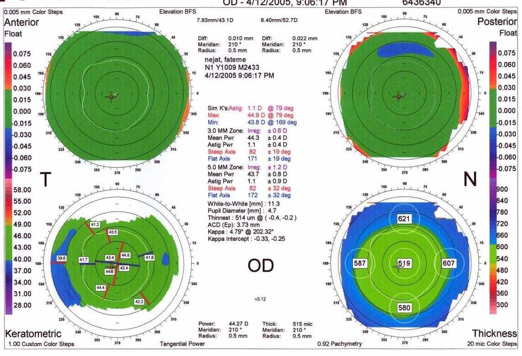
11 Quad map : show 4 pictures Anterior float Posterior float Keratometric pattern Pachymetry
12
13 BEST FIT SPHERE The computer calculates a hypothetical sphere that matches as close as possible to the actual corneal shape being measured. Compares the real surface to the hypothetical sphere showing areas above the surface of the sphere in warm colors and areas below the surface in cool colors
14 Best fit sphere ( BFS ) BFS-eye surface in mm Best fit between eye surface and sphere : GREEN Area under this spherical ideal surface: BLUE Area above this ideal sphere ORANGE-RED

15 Elevation Topology:Central Hill Sharp center Flat periphery The normal cornea is Prolate, meaning that meridional curvature decreases from center to periphery. Prolateness of the normal cornea causes it to rise centrally above the reference sphere. The result is a Central Hill.
16 BFS-eye surface in mm
17 Best fit between eye surface and sphere : GREEN
18 Area under this spherical ideal surface: BLUE
19 Area above this ideal sphere ORANGE-RED

20 Quad Map

21 Quad Map + Normal Band


22 Normal Band Scale Accentuates anomalies Filters small irregularities
23 Quad Map + Normal Band ( NB ) Anterior corneal elevation : NB = ± 25 µ of BFS Posterior corneal elevation : NB = ± 25 µ of BFS Keratometric mean curvature : NB = 40 to 48D Pachymetry : NB = 500 to 600 µ

24

25 Orbscan IIz elevation BFS posterior

26 Orbscan IIz elevation BFS posterior

27 Orbscan IIz elevation BFS posterior

28 Orbscan IIz elevation BFS posterior
29 Quad Map + Normal Band ( NB )
30 Quad Map
31 Quad Map + Normal Band ( NB )
32 Three step rule
33 Quad Map + Normal Band ( NB )
34 Three step rule
35 Quad Map
36 Quad Map + Normal Band ( NB )
37 Quad Map
38 Quad Map + Normal Band ( NB )
39 Three step rule


40 Three step rule
41 Quad Map
42 Quad Map + Normal Band ( NB )
43 Three step rule Three Abnormal Maps: Contraindication

44

45 Keratoconus: Recommended Quad Elevation, Anterior Elevation, Posterior Mean Curvature, Anterior Thickness, Cornea As all four maps are free of axial artifacts, accurate cone locations can be determined in each. Notice that the four cone locations nearly identical
46 Forme Fruste K.C Average post BFS : D (50.2 to 55.3 ) Ratio of radii of Ant to post curvature of cornea 1.21 and 1.27 Average pachymetry difference 7mm to thinnest point 127µ ( 96 to 206µ ) = 100µ
47 Posterior elevation map Posterior BFS > 55D: RED FLAG BUT may be seen in: small cornea : WTW < 11mm a very steep cornea Asian eye More prolateness Posterior BFS :53-55D : YELLOW FLAG
48 Risk Factors for Lasik Candidates : Ratio of radii of ant to post curvatures cornea : >1.21 and <1.27 Post BFS : > 50 D Difference thickness (pachymetry 7mm to thinnest pachymetry : > 90 µ ) Post corneal elevation : > 50 µ

49 Ratio of radii of Ant to post curvature of cornea 1.21 and 1.27
50 Orbscan Risk of Ectasia index: 1.Number of abnormal maps 2.Posterior surface float 3.3 mm and 5 mm irregularity 4.peripheral thickness changes 5.Astigmatism variance between eyes 6.Steep k s mean power map
51 10 µm ANT 20 µm POST
52 Most Astigmatic power ; Simulated K Reading <47.2D: Normal 47.2 to 48.7D: Suspect KCN Higher than 48.7D: Clinical KCN
53 Most Steepest anterior point Difference from BSF Most Steepest posterior point Difference from BSF More than mm Mean=0.048

54 Best Fit shere (Back Surface) Infero-temporal shift Difference>100 Micron
55 Difference between thinnest and the apex of cornea >0.9 to 1 mm

56 -Marked vertical or oblique asymmetry on elevation ant. or post maps -Infero-temporal displacement of highest point on ant and post elevation -Highest point on post elevation is either the thinnest, the point of max. curvature, or coincides with the highest point on anterior elevation
57 Keratoconus Identification with the Orbscan -Mean central thickness < 500 microns -Thinnest point < 470 microns -Difference of > 100 microns from thinnest point to 7 mm zone -Marked eccentric location of the thinnest point
58
59
60 More than 1.5 D (3.0 mm Zone) and >2.00 D (5.00 mm Zone) irregularity is abnormal
61 Orbscan indices for risk of keratectasia Normal Suspect abnormal Posterior BFS <52D 52-55D >55D Difference (most elevated point to BFS) posterior <40µm 40-50µm >50µm Ratio of ant BFSmm/post BFSmm < >1.27 Inferior temporal displacement of highest point (anterior & posterior elevation maps) Correlation of signs in anterior elevation on power map, thinnest point on pachymetry with highest point on posterior elevation Irregularity >1.5 in the 3mm optical zone & >2.0 in 5mm optical zone Axial & tongenital topography map (Rabinowitz-Mc Donnel index): <47.2 D D >48.7D Irregular profile - - > 3D difference in central 3mm Astigmatism variance between eyes - - > 1D Topography pattern - - Assymetric bow-tie, broken bow-tie (Lazy-c) Kr mean power map >46D or total mean power map >45D Pachymetry map Thinnest point >470 µm - <470µm Thinnest point is outside the central 5mm of cornea Difference between pachymetry in 7mm & thinnest pachymetry Difference between pachymetry in 7mm & central reading <90µm µm >100µm - <30µm <20µm Thinnest point >30µm thinner than the central reading
Imaging of the Cornea. Arun Brahma
 Imaging of the Cornea Arun Brahma 1 In the last 30 years we have advanced rapidly in relation to corneal imaging due to Refractive Surgery Keratometer 1880-1990 was the Gold standard. Placido topography-
Wavefront (Center) 502. EMPOWER YOUR PRACTICE WITH comprehensive complete anterior segment analysis
 502. EMPOWER YOUR PRACTICE WITH comprehensive complete anterior segment analysis") Wavefront 584 547 494 493 (Center) 502 496 507 520 529 559 EMPOWER YOUR PRACTICE WITH comprehensive complete anterior segment analysis Narrow Angles Cataracts Glaucoma Risk THE POWER OF THREE The VX130
Wavefront 584 547 494 493 (Center) 502 496 507 520 529 559 EMPOWER YOUR PRACTICE WITH comprehensive complete anterior segment analysis Narrow Angles Cataracts Glaucoma Risk THE POWER OF THREE The VX130
Topography / Tomography 2010 update
 Topography / Tomography 2010 update Anterior Segment Topology-2010 1.Placido based technology with arc step reconstruction τοπογραφία ανάκλασης 2. Scanning Slit / transverse and rotational τοπογραφία προβολής
Holladay Report Pages
 Jack T. Holladay, MD, MSEE, FACS Holladay Report Interpretation Guidelines 2015 Page 1 of 14 Pentacam Interpretation Guideline (Software 1.20b68 or later) Holladay Report 2015 2 Pages This Holladay Report
Scheimpflug topographical changes after Femtosecond LASIK for mixed astigmatism theoretical aspects and case study
 Romanian Journal of Ophthalmology, Volume 61, Issue 1, January-March 2017. pp:69-75 CASE REPORT Scheimpflug topographical changes after Femtosecond LASIK for mixed astigmatism theoretical aspects and case
Introduction. Misconceptions
 ix Even today, corneal topography remains one of the most misunderstood diagnostic tools for the clinician, despite its apparent simplicity, due to unrecognized complexities and oversimplification of formulas.
SCHWIND Diagnostic Devices Experience a new Level of Convenience
 SCHWIND Diagnostic Devices Experience a new Level of Convenience DIAGNOSTIC DEVICES 2 DIAGNOSTIC DEVICES SCHWIND Diagnostic Devices High-precision, multifunctional, user-friendly SCHWIND Diagnostic Devices
The I Kone Lens. Boston XO. Valley CONTAX. Springfield, OR. Manufactured in
 The I Kone Lens Manufactured in Boston XO Valley CONTAX Springfield, OR Contact Lens Fitting Goals for Keratoconus Vision Comfort Corneal Health Fit / Centration Happy Patient Selecting the Best Contact
OCULUS Pentacam Pentacam HR
 OCULUS Pentacam Pentacam HR The Gold Standard in Anterior Segment Tomography We focus on progress Providing the best care to your patients > The eye is extremely sensitive. Loss or impairment of sight
ONEFIT TM MED PUTS YOU IN CONTROL: Full customization when a larger diameter is needed for highly irregular, medically indicated or normal corneas.
 ONEFIT TM MED PUTS YOU IN CONTROL: Full customization when a larger diameter is needed for highly irregular, medically indicated or normal corneas. FITTING GUIDE Applications Design Options IRREGULAR CORNEAS
ISO INTERNATIONAL STANDARD. Ophthalmic instruments Corneal topographers. Instruments ophtalmiques Topographes de la cornée
 INTERNATIONAL STANDARD ISO 19980 First edition 2005-08-15 Ophthalmic instruments Corneal topographers Instruments ophtalmiques Topographes de la cornée Reference number ISO 2005 Provläsningsexemplar /
festta d.o.o Zagreb, Braće Cvijića 32 tel (0) , fax (0)
 , fax (0)") ZASTUPNIK I SERVIS : festta d.o.o. 10000 Zagreb, Braće Cvijića 32 tel. ++385 (0)1 36 35 500, fax. ++385 (0)1 36 36 760 e-mail : festta@festta.hr www.festta.hr OCULUS PENTACAM BASIC CLASSIC We focus on
ZASTUPNIK I SERVIS : festta d.o.o. 10000 Zagreb, Braće Cvijića 32 tel. ++385 (0)1 36 35 500, fax. ++385 (0)1 36 36 760 e-mail : festta@festta.hr www.festta.hr OCULUS PENTACAM BASIC CLASSIC We focus on
ISO Ophthalmic instruments Corneal topographers. Instruments ophtalmiques Topographes de la cornée. Second edition
 INTERNATIONAL STANDARD ISO 19980 Second edition 01-04-01 Ophthalmic instruments Corneal topographers Instruments ophtalmiques Topographes de la cornée Reference number ISO 19980:01(E) ISO 01 ISO 19980:01(E)
Digital Imaging and Communications in Medicine (DICOM)
") Digital Imaging and Communications in edicine (DICO) Supplement 168 Corneal Topography ap Storage SOP Class Prepared by: DICO Working Group 9 1300 N. 17 th Street Suite 1752 Rosslyn, Virginia 22209 USA
Digital Imaging and Communications in edicine (DICO) Supplement 168 Corneal Topography ap Storage SOP Class Prepared by: DICO Working Group 9 1300 N. 17 th Street Suite 1752 Rosslyn, Virginia 22209 USA
IOVS - IOVS R2. Total corneal power estimation: Ray tracing method vs. Gaussian optics formula
 IOVS - IOVS-0-.R Total corneal power estimation: Ray tracing method vs. Gaussian optics formula Journal: Investigative Ophthalmology & Visual Science Manuscript ID: IOVS-0-.R Manuscript Type: Article Date
Damped least-squares approach for point-source corneal topography
 Ophthal. Physiol. Opt. 2009 29: 330 337 Damped least-squares approach for point-source corneal topography Vyacheslav Sokurenko 1 and Vasyl Molebny 1,2 1 National Technical University of Ukraine, Kiev,
Medicine. Longitudinal Evaluation of Cornea With Swept-Source Optical Coherence Tomography and Scheimpflug Imaging Before and After Lasik
 Medicine OBSERVATIONAL STUDY Longitudinal Evaluation of Cornea With Swept-Source Optical Coherence Tomography and Scheimpflug Imaging Before and After Lasik Tommy C.Y. Chan, MMedSc, FRCS, Sayantan Biswas,
An introduction to understanding elevation-based topography: how elevation data are displayed a review
 Review Clinical and Experimental Ophthalmology 2008 doi: 10.1111/j.1442-9071.2008.01821.x An introduction to understanding elevation-based topography: how elevation data are displayed a review Michael
Wavefront Diagnostic. One-Touch COMPREHENSIVE VISUAL ASSESSMENT IN UNDER 90 SECONDS.
 Wavefront Diagnostic One-Touch COMPREHENSIVE VISUAL ASSESSMENT IN UNDER 90 SECONDS. VX120 A GAME CHANGING WAVEFRONT DIAGNOSTIC DEVICE FOR COMPREHENSIVE VISUAL ASSESSMENT REFRACTION AND VISUAL PERFORMANCE
Biometry in the post refractive surgery patient
 Biometry in the post refractive surgery patient The Frontiers of Cataract Surgery Royal Society of Medicine 8 th October 2015 Ali A. Mearza FRCOphth Consultant Ophthalmic Surgeon Imperial College Healthcare
OCULUS Pentacam /Pentacam HR Anterior Segment Tomography
 OCULUS Pentacam /Pentacam HR Anterior Segment Tomography OCULUS Pentacam /Pentacam HR The Gold Standard for Anterior Segment Tomography Since its introduction in 2002 the OCULUS Pentacam has proven to
Total Corneal Power Estimation: Ray Tracing Method versus Gaussian Optics Formula PATIENTS AND METHODS
 Cornea Total Corneal Power Estimation: Ray Tracing Method versus Gaussian Optics Formula Li Wang, 1 Ashraf M. Mahmoud, 2 Betty Lise Anderson, 3 Douglas D. Koch, 1 and Cynthia J. Roberts 2 PURPOSE. To evaluate
3D SWEPT SOURCE OCT. Very high scanning speed: 30,000 A-Scans/sec. 130,800 A-Scans. Cut plane 16 x 16 x 6 mm. Topo/Pachy Map in 0.3 sec.
 3D SWEPT SOURCE OCT FOURIER DOMAIN OCT CASIA SS-1000 Very high scanning speed: 30,000 A-Scans/sec. 130,800 A-Scans Cut plane 16 x 16 x 6 mm Topo/Pachy Map in 0.3 sec. Free adjustable display in 2D and
Fitting Keratoconic Patients with Rigid Gas Permeable Contact Lenses Using Topography
 Fitting Keratoconic Patients with Rigid Gas Permeable Contact Lenses Using Topography Jon Wieringa Michigan College of Optometry 2006 Fitting Keratoconic patients with Rigid Gas Permeable Contact Lenses
Aberration Theory. Lens. Optical systems convert the shapes of wavefronts
 Aberration Theory Lens Optical systems convert the shapes of wavefronts Aberrations A perfectly spherical wave will converge to a point. Any deviation from the ideal spherical shape is said to be an aberration.
LASIK experience with the FS200 femto and EX500 excimer (the Refractive Suite)
") LASIK experience with the FS200 femto and EX500 excimer (the Refractive Suite) A. John Kanellopoulos, MD Clinical Professor of Ophthalmology, NYU, New York, USA Medical Director, Laservision.gr Institute,
LASIK experience with the FS200 femto and EX500 excimer (the Refractive Suite) A. John Kanellopoulos, MD Clinical Professor of Ophthalmology, NYU, New York, USA Medical Director, Laservision.gr Institute,
PalmScan PRO 5 in 1 Biometer Your Complete Biometry System - Fully Configurable
 B-Scan A-Scan Pachymeter Keratometer UBM PalmScan PRO 5 in 1 Biometer Your Complete Biometry System - Fully Configurable A-Scan + IOL Calculator Keratometer Pachymeter B-Scan UBM www.micromedinc.com 818.222.3310
Over the past 20 years, corneal shape analysis has evolved
 Construction of a 3-D Atlas of Corneal Shape Jean-François Laliberté, 1 Jean Meunier, 2,3 Miguel Chagnon, 4 Jean-Claude Kieffer, 5 and Isabelle Brunette 1,3 PURPOSE. A methodology is proposed to build
Scheimpflug photography keratometry readings for routine intraocular lens power calculation
 ARTICLE Scheimpflug photography keratometry readings for routine intraocular lens power calculation H. John Shammas, MD, Kenneth J. Hoffer, MD, Maya C. Shammas, MD PURPOSE: To prospectively evaluate keratometry
HOYA isert 351 toric
 HOYA isert 351 toric Patient selection Suitable patient: ametropia with corneal astigmatism > 1.0 D regular astigmatism stable cornea wish for glasses independence / realistic expectations and motivation
"Using a Systematic Approach when Fitting Keratoconus, Irregular and Post Surgical Corneas" Dr. Paul Rose OD
 Dr. Paul Rose OD New Zealand New Zealand Some facts Has 4m people and 40m sheep Is a 3 hours flight from Australia Is an 13 hour direct flight from Vancouver Local sport is rugby/ All Blacks Home of the
Raytracing for IOL Power Calculation
 Raytracing for IOL Power Calculation Paul-Rolf Preußner 1, Oliver Findl 2, Thomas Olsen 3, Peter Hoffmann 4, Jochen Wahl 1 1 University Eye Hospital Mainz, Germay, 2 Hanusch Eye Hospital, Vienna, Austria,
We focus on progress OCULUS KERATOGRAPH
 We focus on progress OCULUS KERATOGRAPH 3 in 1 : Keratometer Topograph Pupillometer precise, easy and intuitive Built-in keratometer and automatic measurement release guarantee reproducibility Extremely
Welcome to the World of Scleral Lenses (Fitting Workshop)
") Welcome to the World of Scleral Lenses (Fitting Workshop) 1409 Kensington Blvd. Bowling Green, OH 43402 Mile Brujic, O.D., F.A.A.O. Dave Kading, O.D., F.A.A.O. Lynette Johns, O.D., F.A.A.O. Summary This
Welcome to the World of Scleral Lenses (Fitting Workshop) 1409 Kensington Blvd. Bowling Green, OH 43402 Mile Brujic, O.D., F.A.A.O. Dave Kading, O.D., F.A.A.O. Lynette Johns, O.D., F.A.A.O. Summary This
Eye & Health Care. NIDEK Co, Ltd. Product Development E/X3, Medical Division
 NIDEK Co, Ltd. Product Development E/X3, Medical Division OPD-Scan III Development team What s new of OPD-ScanⅢ Ease of use Simple operation MAP & Layout selection Must select the Maps,Layout and Settings
(Goal 3) (Goal 3) (Goals 4 and 5) (Goals 4 and 5)
 (Goal 3) (Goals 4 and 5) (Goals 4 and 5)") 10 This thesis addresses the measurement of geometrical properties (surface geometry, tilt and decentration) of the crystalline lens in normal eyes, and their changes with accommodation. In addition, it
10 This thesis addresses the measurement of geometrical properties (surface geometry, tilt and decentration) of the crystalline lens in normal eyes, and their changes with accommodation. In addition, it
Zeiss VisuMax/MEL for LASIK and Keratoplasty. William W. Culbertson, MD; Bascom Palmer Eye Institute, Miami, FL
 Zeiss VisuMax/MEL for LASIK and Keratoplasty William W. Culbertson, MD; Bascom Palmer Eye Institute, Miami, FL 1 VisuMax Femtosecond Laser Precision Low IOP Low energy Gentle on patient Minimal applanation
Effect of lamellar flap location on corneal topography after laser in situ keratomileusis
 Effect of lamellar flap location on corneal topography after laser in situ keratomileusis Neal E. Ginsberg, MD, Peter S. Hersh, MD ABSTRACT Purpose: To investigate the effect of hinge position on corneal
Keratoconus is a bilateral non-inflammatory degenerative
 Basic Research Mathematical analysis of corneal remodelling after intracorneal ring surgery in keratoconus Elias F. Jarade 1,2, Elise Slim 1,3, Carole Cherfan 1, Hala El Rami 3, Toufic Hassan 3, Elias
SURFACE BOUNDARY MEASUREMENT USING 3D PROFILOMETRY
 SURFACE BOUNDARY MEASUREMENT USING 3D PROFILOMETRY Prepared by Craig Leising 6 Morgan, Ste156, Irvine CA 92618 P: 949.461.9292 F: 949.461.9232 nanovea.com Today's standard for tomorrow's materials. 2013
GONIOSCOPY Gonioscopy is a technique that allows visualization of the anterior chamber angle structures and is used to diagnose abnormalities of the a
 Gonioscopic Evaluation of the Anterior Chamber Angle University of Milan Bicocca June 2010 Anthony Cavallerano, O.D. VA Boston Health Care System Draft Only The New England College of Optometry Boston
Evaluations and geometrical measurements of the human eye in order to establish the design parameters for the customized contact lens
 IOP Conference Series: Materials Science and Engineering PAPER OPEN ACCESS Evaluations and geometrical measurements of the human eye in order to establish the design parameters for the customized contact
Quantitative Three-Dimensional Imaging of the Posterior Segment with the Heidelberg Retina Tomograph
 Quantitative Three-Dimensional Imaging of the Posterior Segment with the Heidelberg Retina Tomograph Heidelberg Engineering GmbH, Heidelberg, Germany Contents 1 Introduction... 1 2 Confocal laser scanning
Optimal cornea shape design problem for corneal refractive surgery
 10 th World Congress on Structural and Multidisciplinary Optimization May 19-4, 013, Orlando, Florida, USA Optimal cornea shape design problem for corneal refractive surgery Takaki Nakayama, Hisashi Naito,
26-th ECMI Modelling Week Final Report Dresden, Germany
 26-th ECMI Modelling Week Final Report 19.08.2012 25.08.2012 Dresden, Germany Group 4 Mathematics of the eye: modelling corneal curvature. Federica Bani Dept. of Mathematical Sciences, University of Florence,
KERATOCONUS IS THE MOST FREQUENT CORNEAL
 Reproducibility and Repeatability of Central Corneal Thickness Measurement in Keratoconus Using the Rotating Scheimpflug Camera and Ultrasound Pachymetry UGO DE SANCTIS, ALESSANDRO MISSOLUNGI, BERNARDO
CWhatUC : A Visual Acuity Simulator Daniel D. Garcia a, Brian A. Barsky a,b, Stanley A. Klein b
 CWhatUC : A Visual Acuity Simulator Daniel D. Garcia a, Brian A. Barsky a,b, Stanley A. Klein b a University of California, EECS Computer Science Division, 387 Soda Hall # 1776, Berkeley CA 94720-1776
A software simmulation of Hartmann-Schack patterns for real corneas
 A software simmulation of Hartmann-Schack patterns for real corneas L. A. Carvalho*, Jarbas C. Castro*, P. Schor, W. Chamon *Instituto de Física de São Carlos (IFSC - USP), Brazil lavcf@ifsc.sc.usp.br
EPSRC Centre for Doctoral Training in Industrially Focused Mathematical Modelling
 EPSRC Centre for Doctoral Training in Industrially Focused Mathematical Modelling More Accurate Optical Measurements of the Cornea Raquel González Fariña Contents 1. Introduction... 2 Background... 2 2.
Updated Protocol to Provide Best Vision after CXL in Keratoconus
 Updated Protocol to Provide Best Vision after CXL in Keratoconus Mohamed Shafik Shaheen MD, PhD Professor of Ophthalmology, University of Alexandria, Horus Vision Correction Center, Egypt What is after
IOL Calculation after Corneal Refractive Surgery
 P. Zotta Abstract Cataract surgery after corneal refractive surgery can be challenging due to the difficulty with accurate IOL power determination. An increasing number of methods designed to measure IOL
LENSTAR LS 900 Improving outcomes
 LENSTAR LS 900 Improving outcomes Tradition and Innovation Since 1858, visionary thinking and a fascination with technology have guided us to develop innovative products of outstanding reliability: Anticipating
Anterior corneal asphericity calculated by the tangential radius of curvature
 Anterior corneal asphericity calculated by the tangential radius of curvature Jinglu Ying Bo Wang Mingguang Shi Journal of Biomedical Optics 17(7), 075005 (July 2012) Anterior corneal asphericity calculated
Measure at the speed of light...
 Measure at the speed of light... LENSTAR LS 900 Biometry Explore new dimensions... Complete optical biometer including CCT and lens thickness Align once, get all results fast biometrical assessment Non
Conceptual Physics 11 th Edition
 Conceptual Physics 11 th Edition Chapter 28: REFLECTION & REFRACTION This lecture will help you understand: Reflection Principle of Least Time Law of Reflection Refraction Cause of Refraction Dispersion
CHARACTERIZATION OF FISH SCALE USING 3D PROFILOMETRY
 CHARACTERIZATION OF FISH SCALE USING 3D PROFILOMETRY 2 4 6 8 1 mm 1 2 3 4 5 6 7 8 mm Prepared by Andrea Novitsky 6 Morgan, Ste156, Irvine CA 92618 P: 949.461.9292 F: 949.461.9232 nanovea.com Today's standard
Videokeratography for Quantitative Surface Analysis of Used Soft Contact Lenses
 ELSEVIER Videokeratography for Quantitative Surface Analysis of Used Soft Contact Lenses Naoyuki Maeda,* Stephen D. Klyce, * Michael K. Smolek, t Hikaru Hamano,* Sachiko Mitsunaga * and Kiyoshi Watanabe*
ORIGINAL ARTICLE. Simulation of Machine-Specific Topographic Indices for Use Across Platforms
 1040-5488/06/8309-0682/0 VOL. 83, NO. 9, PP. 682 693 OPTOMETRY AND VISION SCIENCE Copyright 2006 American Academy of Optometry ORIGINAL ARTICLE Simulation of Machine-Specific Topographic Indices for Use
Detection of Keratoconus by Semi-Supervised Learning
 Keywords: Semi Supervised Learning, Manifold Learning, Multi Dimensional Scaling, IsoMap Abstract Keratoconus, is a non-inflammatory disorder of the eye in which structural changes within the cornea cause
City Research Online. Permanent City Research Online URL:
 Gruppetta, S, Koechlin, L, Lacombe, F & Puget, P (0015). Curvature sensor for the measurement of the static corneal topography and the dynamic tear film topography in the human eye.. Opt Lett, 30(20),
Overview. Clinical Indications. Clinical Indications 10/4/2017
 Scleral Lenses for Dummies -a guide to scleral lens design, fitting, and troubleshooting Julie DeKinder, O.D. Clinical Associate Professor Overview Clinical Indications Advantages and Challenges Terminology
Detection of Keratoconus by Semi-Supervised Learning
 Deepthi Cheboli Indian Institute of Technology Madras, India Balaraman Ravindran Indian Institute of Technology Madras, India keepthi@cse.iitm.ac.in ravi@cse.iitm.ac.in Keywords: Semi Supervised Learning,
DISSERTATION. presented by Nina Korablinova born in Kaliningrad, Russia
 DISSERTATION submitted to the Combined Faculties for the Natural Sciences and Mathematics of the Ruperto-Carola University of Heidelberg, Germany for the degree of Doctor of Natural Sciences presented
Spherical Soft Contact Lenses
 Spherical Soft Contact Lenses Principles of Design and Fitting Module 3, IACLE created by: L Sorbara, OD, MSc, FAAO, Dipl C&CL presented by: M. Steenbakkers, OD, FAAO Soft Contact Lenses Primary lens type
STEEL SURFACE CHARACTERIZATION USING 3D PROFILOMETRY
 STEEL SURFACE CHARACTERIZATION USING 3D PROFILOMETRY Prepared by Andrea Novitsky 6 Morgan, Ste156, Irvine CA 92618 P: 949.461.9292 F: 949.461.9232 nanovea.com Today's standard for tomorrow's materials.
MICRO SCRATCH DEPTH USING 3D PROFILOMETRY
 MICRO SCRATCH DEPTH USING 3D PROFILOMETRY Prepared by Jorge Ramirez 6 Morgan, Ste156, Irvine CA 92618 P: 949.461.9292 F: 949.461.9232 nanovea.com Today's standard for tomorrow's materials. 2012 NANOVEA
Alicona Specifications
 Alicona Specifications The Alicona optical profilometer works using focus variation. Highest Specifications Table 1: Highest specification for optical profilometer parameters. Parameter Specification *Vertical
PREMIER DIAGNOSTIC ULTRASOUND. Diagnostic ultrasound. that delivers unparalleled. image resolution.
 PREMIER DIAGNOSTIC ULTRASOUND Diagnostic ultrasound that delivers unparalleled image resolution. High Resolution Goes Ultra THE NEW GENERATION EYE CUBED TM M A K E S I T P O S S I B L E T O EVALUATE OCULAR
Object surface for applying a modified Hartmann test to measure corneal topography
 Object surface for applying a modified Hartmann test to measure corneal topography Yobani Mejía-Barbosa and Daniel Malacara-Hernández A modified Hartmann test is proposed for measuring corneal topography.
ORIGINAL ARTICLE. Repeatability and Reproducibility of Central Corneal Thickness Measurement With Pentacam, Orbscan, and Ultrasound
 1040-5488/05/8210-0892/0 VOL. 82, NO. 10, PP. 892 899 OPTOMETRY AND VISION SCIENCE Copyright 2005 American Academy of Optometry ORIGINAL ARTICLE Repeatability and Reproducibility of Central Corneal Thickness
TECHNICAL REPORT. Corneal Topographer Based on the Hartmann Test. Yobani Mejía* and Janneth C. Galeano
 1040-5488/09/8604-0370/0 VOL. 86, NO. 4, PP. 370 381 OPTOMETRY AND VISION SCIENCE Copyright 2009 American Academy of Optometry TECHNICAL REPORT Corneal Topographer Based on the Hartmann Test Yobani Mejía*
Corneal surgery and corneal replacement techniques have
 Cornea Corneal Shape, Volume, and Interocular Symmetry: Parameters to Optimize the Design of Biosynthetic Corneal Substitutes Georges M. Durr, 1 Edouard Auvinet, 2 Jeb Ong, 1,3 Jean Meunier, 1,2 and Isabelle
TISSUE SURFACE TOPOGRAPHY USING 3D PRFILOMETRY
 TISSUE SURFACE TOPOGRAPHY USING 3D PRFILOMETRY Prepared by Craig Leising 6 Morgan, Ste156, Irvine CA 92618 P: 949.461.9292 F: 949.461.9232 nanovea.com Today's standard for tomorrow's materials. 2011 NANOVEA
Light: Geometric Optics (Chapter 23)
") Light: Geometric Optics (Chapter 23) Units of Chapter 23 The Ray Model of Light Reflection; Image Formed by a Plane Mirror Formation of Images by Spherical Index of Refraction Refraction: Snell s Law 1
Light: Geometric Optics (Chapter 23) Units of Chapter 23 The Ray Model of Light Reflection; Image Formed by a Plane Mirror Formation of Images by Spherical Index of Refraction Refraction: Snell s Law 1
Lecture 4 Recap of PHYS110-1 lecture Physical Optics - 4 lectures EM spectrum and colour Light sources Interference and diffraction Polarization
 Lecture 4 Recap of PHYS110-1 lecture Physical Optics - 4 lectures EM spectrum and colour Light sources Interference and diffraction Polarization Lens Aberrations - 3 lectures Spherical aberrations Coma,
NEW! PORTABLE DIAGNOSTIC ULTRASOUND PLATFORM. Considered to be the gold standard in ophthalmic diagnostic ultrasound,
 NEW! PORTABLE DIAGNOSTIC ULTRASOUND PLATFORM Considered to be the gold standard in ophthalmic diagnostic ultrasound, Eye Cubed features advanced movie mode using the fastest sampling Eye One rate available,
Lenses for your lifestyle FREE FORM LENSES MANUFACTURED IN THE UK
 Lenses for your lifestyle FREE FORM LENSES MANUFACTURED IN THE UK Index Technologies... Camber... Digital Ray-Path... Surface Power... 5 Smart Add... 5 Personalization parameters... 6 Lens Portfolio...
A. K. Srivastava, K.C. Sati, Satyander Kumar alaser Science and Technology Center, Metcalfe House, Civil Lines, Delhi , INDIA
 International Journal of Scientific & Engineering Research Volume 8, Issue 7, July-2017 1752 Optical method for measurement of radius of curvature of large diameter mirrors A. K. Srivastava, K.C. Sati,
PLANO LENSES. Memo Written by D. B. Whitney on April 28, 1985 American Optical
 PLANO LENSES Memo Written by D. B. Whitney on April 28, 1985 American Optical The subject of plano lenses is one about which much has been said and written. Even so, I think it might be well for me to
Nicholas J. Giordano. Chapter 24. Geometrical Optics. Marilyn Akins, PhD Broome Community College
 Nicholas J. Giordano www.cengage.com/physics/giordano Chapter 24 Geometrical Optics Marilyn Akins, PhD Broome Community College Optics The study of light is called optics Some highlights in the history
STUDY ON LASER SPECKLE CORRELATION METHOD APPLIED IN TRIANGULATION DISPLACEMENT MEASUREMENT
 STUDY ON LASER SPECKLE CORRELATION METHOD APPLIED IN TRIANGULATION DISPLACEMENT MEASUREMENT 2013 г. L. Shen*, D. G. Li*, F. Luo** * Huazhong University of Science and Technology, Wuhan, PR China ** China
nstruments.com ADVANCED SURFACE METROLOGY
 www.rhopoin nstruments.com ADVANCED SURFACE METROLOGY Fast full field surface measurement Suitable for all finishes, from ma to mirror On-screen image analysis Powerful analysis with portability POWERED
CARBON FIBER SURFACE MEASUREMENT USING 3D PROFILOMETRY
 CARBON FIBER SURFACE MEASUREMENT USING 3D PROFILOMETRY Prepared by Craig Leising 6 Morgan, Ste156, Irvine CA 92618 P: 949.461.9292 F: 949.461.9232 nanovea.com Today's standard for tomorrow's materials.
AmericanNationalStand
 ANSI Z80.23-2008 (R2013) ANSIZ80.23-2008 AmericanNationalStand ard for Ophthalmics Corneal Topography Systems Standard Terminology, Requirements ANSI Z80.23-2008 (R2013) (Revision of ANSI Z80.23-1999)
Advanced Lens Design
 Advanced Lens Design Lecture 9: Field flattening 04--6 Herbert Gross Winter term 04 www.iap.uni-ena.de Preliminary Schedule.0. Basics Paraxial optics, imaging, Zemax handling 8.0. Optical systems Optical
LENSTAR 900 Improving outcomes
 LENSTAR 900 Improving outcomes Tradition and Innovation Since 1858, visionary thinking and a fascination with technology have guided us to develop innovative products of outstanding reliability: Anticipating
SURFACE TEXTURE CONSISTENCY USING 3D PROFILOMETRY
 SURFACE TEXTURE CONSISTENCY USING 3D PROFILOMETRY Prepared by Craig Leising 6 Morgan, Ste156, Irvine CA 92618 P: 949.461.9292 F: 949.461.9232 nanovea.com Today's standard for tomorrow's materials. 2013
Chapter 7: Geometrical Optics. The branch of physics which studies the properties of light using the ray model of light.
 Chapter 7: Geometrical Optics The branch of physics which studies the properties of light using the ray model of light. Overview Geometrical Optics Spherical Mirror Refraction Thin Lens f u v r and f 2
DICOM Correction Proposal
 DICOM Correction Proposal STATUS Draft Date of Last Update 2018/06/26 Person Assigned Don van Syckle Submitter Name Submission Date 2018/03/09 Patrick A. Nast (patrick.nast@zeiss.com) Correction Number
2/26/2016. Chapter 23 Ray Optics. Chapter 23 Preview. Chapter 23 Preview
 Chapter 23 Ray Optics Chapter Goal: To understand and apply the ray model of light. Slide 23-2 Chapter 23 Preview Slide 23-3 Chapter 23 Preview Slide 23-4 1 Chapter 23 Preview Slide 23-5 Chapter 23 Preview
Light: Geometric Optics
 Light: Geometric Optics 23.1 The Ray Model of Light Light very often travels in straight lines. We represent light using rays, which are straight lines emanating from an object. This is an idealization,
STEP HEIGHT MEASUREMENT OF PRINTED ELECTRODES USING 3D PROFILOMETRY
 STEP HEIGHT MEASUREMENT OF PRINTED ELECTRODES USING D PROFILOMETRY Prepared by Andrea Herrmann Morgan, Ste, Irvine CA 98 P: 99..99 F: 99..9 nanovea.com Today's standard for tomorrow's materials. NANOVEA
Refractive correction method for digital charge-coupled device-recorded Scheimpflug photographs by means of ray tracing
 Journal of Biomedical Optics 10(2), 024003 (March/April 2005) Refractive correction method for digital charge-coupled device-recorded Scheimpflug photographs by means of ray tracing Wolfgang Fink University
PHYSICS. Chapter 34 Lecture FOR SCIENTISTS AND ENGINEERS A STRATEGIC APPROACH 4/E RANDALL D. KNIGHT
 PHYSICS FOR SCIENTISTS AND ENGINEERS A STRATEGIC APPROACH 4/E Chapter 34 Lecture RANDALL D. KNIGHT Chapter 34 Ray Optics IN THIS CHAPTER, you will learn about and apply the ray model of light Slide 34-2
KR-1 Auto Kerato-Refractometer
 KR-1 Auto Kerato-Refractometer The next generation of refractive care Function and aesthetics combined in the KR-1 The KR-1 is a revolutionary auto Kerato-Refractometer. The tiltable and rotatable touchscreen
Calibration of a portable interferometer for fiber optic connector endface measurements
 Calibration of a portable interferometer for fiber optic connector endface measurements E. Lindmark Ph.D Light Source Reference Mirror Beamsplitter Camera Calibrated parameters Interferometer Interferometer
New Opportunities for 3D SPI
 New Opportunities for 3D SPI Jean-Marc PEALLAT Vi Technology St Egrève, France jmpeallat@vitechnology.com Abstract For some years many process engineers and quality managers have been questioning the benefits
L880E. Slit lamps L880E. 5 steps magnification microscope with achromatic optics REF
 Slit lamps L880E 5 steps magnification microscope with achromatic optics REF 7460034 The 5 steps magnification microscope with achromatic optics gives sharp and grips images. Clearness > The five primary
ksa MOS Ultra-Scan Performance Test Data
 ksa MOS Ultra-Scan Performance Test Data Introduction: ksa MOS Ultra Scan 200mm Patterned Silicon Wafers The ksa MOS Ultra Scan is a flexible, highresolution scanning curvature and tilt-measurement system.
MICROSPHERE DIMENSIONS USING 3D PROFILOMETRY
 MICROSPHERE DIMENSIONS USING 3D PROFILOMETRY Prepared by Craig Leising 6 Morgan, Ste156, Irvine CA 92618 P: 949.461.9292 F: 949.461.9232 nanovea.com Today's standard for tomorrow's materials. 2010 NANOVEA