Radiation Oncology treatment facility design. Simulators, CT scanners, HDR Brachytherapy
|
|
|
- Philip Garrett
- 6 years ago
- Views:
Transcription


1 Radiation Oncology treatment facility design Simulators, CT scanners, HDR Brachytherapy McGill MDPH 613 Fall 2004
2 UNITS For this class only: 1 R = 1 cgy = 1 csv = 10 msv

3 Reference book McGinley NCRP 49 NCRP 51 Health Physics notes, Robert Corns Safety code 20A, Health Canada
4 Radiation Oncology Linear accelerator Brachytherapy CT simulator simulator
5 Basic shielding concepts Establish a target dose-rate at a certain point behind a barrier Calculate barrier thickness necessary to achieve the target dose rate
6 Shielding considerations Machine workload Type of person to protect NEW Public Type of space to protect Public access area Restricted access
7 Shielding considerations Type of radiation Primary beam incidence Primary beam scatter Patient scatter Leakage radiation

8 Simulator Operates with same geometry as LINAC Radiation source is diagnostic x-ray tube Capable of radiographic and fluoroscopic functions
9 Simulator Most exposures made in fluoroscopy mode X-ray beam collimated, always incident on image intensifier (II) Primary beam significantly attenuated by patient and II
10 Shielding materials Lead (Pb) backed gypsum board (dry wall) Shielding provided to height of 7 feet unless space above is occupied Viewing window with lead glass is used at console area
11 Types of barriers Primary barriers Attenuate primary (direct) beam Secondary barriers Leakage Patient scatter Wall scatter
12 Simulator room secondary isocenter primary Target rotational plane Lead glass window Simulator control area shielded door
13 Primary beam Barrier thickness depends on: Distance to POI from source (d) Target dose rate (P) Workload (W) Occupancy (T) Usage (U) *Patient and table attenuation not taken into account
14 Basic situation s source isocenter 1 m d
15 Primary barrier At isocenter max FS is 40 x 40 cm 2 Largest dimension is diagonal (56 cm) At barrier this will project to larger size at iso ~ 56 cm at barrier ~ 200 cm
16 Simulators: Primary beam K ux is transmission factor Expressed in (R/mA min) at 1m NCRP 49 (1976) K ux = Pd 2 WUT
17 Target dose rate P Group ICRP 60 Dose limit Exposure rate Exposure rate (msv/y) (R/week) (R/y) NEW ~ 2 Public ~ 0.1 *1 year has 50 weeks of 40 hrs/week or 2000 hr/year ** diagnostic X-ray installations are not licensed by CNSC but may fall under provincial regulations
18 Workload W workload expressed in ma-min/wk: Radiography 50 patient/wk x 500 mas/patient x 1 s/60 min = 400 ma min/wk Fluoroscopy K ux = 50 patient/wk x 5 ma/patient x 1 min = 250 ma min/wk Pd 2 W UT W = 1000 ma-min/wk

19 Typical workload
20 Usage factor U U Accounts for beam orientation Isocentric units have same usage for floors, ceiling, and walls. U = 0.25 Pd 2 K ux = W U T
21 Occupancy factor T T 1 1/4 1/16 Type of area Full Offices, shops, labs, living area Partial Corridors, restrooms, parking Occasional Waiting room, stairway, janitor closet Pd 2 K ux = W U T
22 Transmission factor Kux
23 Transmission - lead
24 Transmission - concrete (cm)
25 Simulators: Leakage Assumption leakage is 0.1 R/hr at 1m Shielded to a factor of 600 per minute B = 600 I Pd s 2 WT
26 Simulators: Leakage B is the factor by which the intensity of radiation (P o ) must be reduced to achieve the target dose rate P P 600 I Pd s 2 B = B = P o WT
27 Simulators: Leakage I is the tube current (ma) d s is the distance from source to POI B = 600 I Pd s 2 WT
28 TVL - Tenth Value Layer 1 n = log ( ) B HVL - Half Value Layer 1 TVL = 3.32 HVL
29 TVL and HVL 1 2 x = 1 10 = 2 x 10 x log 2 = log 10 x = 3.32
30 TVL-HVL
31 Simulators: Scatter Scattered x-rays have same barrier penetration as primary beam NCRP 49 (1976) K = 400 P D 2 d 2 F awt
32 Simulators: Scatter D is the distance from the source to scatterer d is the distance from scatterer to POI F is the field area on patient a is the scatter fraction K = 400 P D 2 d 2 F awt

33 Scatter fraction
34 Lead Glass Leaded glass may be used for patient observation window thickness (mm) Lead 1.9 (1/16 ) 2.6 (3/32 ) 3.1 (1/8 ) Glass X-ray kv p Cost/m
35 Doors Doors contain the lead equivalent thickness required for secondary barrier shielding 1-2 mm Pb in wood Make sure door is not in primary beam
36 Simulator (125 kv p ) room B secondary Target rotational plane isocenter primary A Determine wall thickness (concrete and Pb) required for POI A and B. What would be the thickness of the lead glass required for the console area? Lead glass window d iso to POI is 4m Simulator control area A is an office T =1 shielded door B is a waiting room T = 1/16 U = 0.25 for simulators W = 1000 ma min/week
37 Simulator room Determine target P At A, office with NEW (+ALARA?) 20 msv/year (ICRP 60) Target dose rate is 20 msv/yr = 2 R/yr = 0.04 R/wk
38 Simulator room P = 0.04 R/week d = 4m W = 1000 ma min/week U = 0.25, T = 1 Pd 2 K ux = = WUT
39 Simulator room K ux = 0.04 R/wk x ma min/wk x 0.25 x 1 K ux = R/mA min at 1m ~ 12 cm concrete or 1-2 mm Pb
40 Simulator example
41 Simulator example cm
42 Leakage barrier Leakage barrier (at B ) I = 5 ma, T = 1/16, d s = 4m B = 600 I Pd s 2 WT
43 Simulator room Leakage barrier (at B) B = 600 I Pd s 2 WT = 600 x (5) x R/wk x 4 2 = x 1/16 = TVLs or HVLs
44 Simulator room 125 kvp = x 6.6 cm = 1.2 cm 125 kvp = x 0.93 = 1.7 mm Lead glass equivalent = 8 mm
45 Scatter barrier (at B ) Scatter barrier F = 20 2 cm 2, T = 1/16, D = 1m, d = 4m a = P D 2 d 2 K = = F awt Equivalent to about 1 cm concrete so use leakage calculation
46 Simulator example cm


47 CT simulator room Dedicated CT scanner for radiotherapy Flat table, lasers, big bore X-ray tube operating at 125 kvp and 250 mas Primary beam is inherently shielded and U = 1
48 CT simulator room control area waiting room
49 CT simulator Workload W = 50 pt/wk x 100 slices/pt = 5000 slices/wk Isodose plots are provided from the manufacturer to estimate the dose rate in different parts of the room
50 CT scanner dose
51 CT scanner dose The workload at any unprotected point in the room: D = W D o T D o is the isodose value, T is the occupancy
52 CT simulator room The required transmission is: TR = P / D = P / W D o T and TR = X s /X o X s = X o TR X s = X o P / W D o T X s is the shielded intensity X o is conversion R per ma min at 1m
53 CT simulator room R per ma min at 1 m from the x-ray target kv Xo
54 CT simulator room Calculate the barrier thickness required at point X. 10 patients are scanned a day, 100 slices each patient. The area to be protected is a public access area with occupancy T=1. X a) Calculate the Workload b) Calculate the P c) Determine the thickness of lead required The scanner operates at 125 kv and 200 ma for 1.5s per slice.
55 X s = X o P / W D o T Workload W 10 pt/day x 100 slices/pt x 5 day/wk = 5000 slices/wk Target dose rate P Public limit 1 msv/year is 0.02 msv/wk Dose from isodoses D o D o = 0.03 R per ma min conversion X o X o = 0.95
56 CT simulator room X s = X o P / W D o T = (0.95 x 0.02 msv/wk) 5000 slices/wk x 0.02 x 10⁻³ mgy X s = 0.19
57 X s = X o P / W D o T X s = X o P / W D o T = (0.95 x 0.02 msv/wk) 5000 slices/wk x 0.03 x 10⁻³ mgy = cm


58 HDR brachytherapy Ir Ci, welded to flexible steel cable Remotely controlled Source driven out of safe through a catheter to patient Typical room ~ 60 cm concrete
59 HDR brachytherapy Shielding calculations based on transmission factor B, where: B = Pd 2 WT d is distance from source to POI
60 HDR brachytherapy Workload based on the total dose delivered to all patients to be treated per week W is also function of source activity and treatment time W = Γ f A t
61 HDR brachytherapy W = Γ f A t Γ exposure rate constant Relates exposure rate to activity at 1m For Ir-192 Γ = 0.48 m 2 R/hr Ci F factor relates cgy to R and is 0.96 cgy/r for Ir-192 t treatment time per week T = dose x #patients / 1cm
62 HDR brachytherapy Calculate thickness of concrete required for a 10 Ci Ir-192 installation that treats 25 pt/wk to a dose of 10 Gy per patient. The dose is delivered at 1 Gy per minute. d = 2 m, and the POI is a control area T = 1, we want to protect NEWs. Workload Target dose rate
63 HDR brachytherapy W = Γ f A t Workload Time = dose / doserate = 25 patients x 10 Gy / 1 Gy/min = 250 min = 4.16 hr/wk W = 0.48 R/hr Ci x 0.96 cgy/r x 10 Ci x 4.16 hr/wk = 19.2 Target dose rate NEW 0.04 cgy/wk (or csv)
64 HDR brachytherapy Pd 2 B = = WT From graph ~ 48 cm concrete
65 Brachytherapy - concrete
66 Brachytherapy - lead

67 Lead underwear
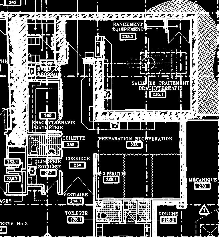
68 MGH brachytherapy/sim
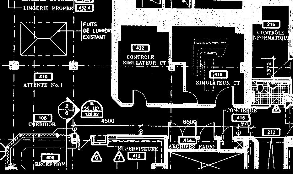
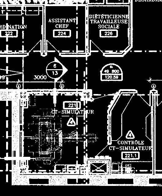
69 MGH CT simulators 1
70 MGH CT simulators 2
Shielding Design Methods for Radiation Oncology Departments
 Shielding Design Methods for Radiation Oncology Departments Melissa C. Martin, M.S., FACR, FACMP Therapy Physics Inc., Gardena, CA 90248 Melissa@TherapyPhysics.com ACMP 25th Annual Meeting Seattle, WA
Dose Distributions. Purpose. Isodose distributions. To familiarize the resident with dose distributions and the factors that affect them
 Dose Distributions George Starkschall, Ph.D. Department of Radiation Physics U.T. M.D. Anderson Cancer Center Purpose To familiarize the resident with dose distributions and the factors that affect them
RadShield: semiautomated shielding design using a floor plan driven graphical user interface
 JOURNAL OF APPLIED CLINICAL MEDICAL PHYSICS, VOLUME 17, NUMBER 5, 016 RadShield: semiautomated shielding design using a floor plan driven graphical user interface Matthew C. DeLorenzo, 1a Dee H. Wu, 1
Photon beam dose distributions in 2D
 Photon beam dose distributions in 2D Sastry Vedam PhD DABR Introduction to Medical Physics III: Therapy Spring 2014 Acknowledgments! Narayan Sahoo PhD! Richard G Lane (Late) PhD 1 Overview! Evaluation
Future Topics. Projection Imaging Dose Reporting, XA 3D Volume Objects. for DICOM WG-02. Presented by Heinz Blendinger, Siemens Medical Solutions
 Future Topics for Projection Imaging Dose Reporting, XA 3D Volume Objects DICOM WG-02 Presented by Heinz Blendinger, Siemens Medical Solutions 1 Presentation outline Dose Reporting Why Dose Reporting?
Shielding factors for traditional safety glasses
 Shielding factors for traditional safety glasses Malcolm McEwen, Hong Shen and Ernesto Mainegra-Hing Ionizing Radiation Standards, National Research Council Canada Alan DuSautoy, Radiation and Health Sciences
Introduction to Biomedical Imaging
 Alejandro Frangi, PhD Computational Imaging Lab Department of Information & Communication Technology Pompeu Fabra University www.cilab.upf.edu X-ray Projection Imaging Computed Tomography Digital X-ray
Use of Monte Carlo modelling in radiotherapy linac design. David Roberts, PhD Senior Physicist Elekta
 Use of Monte Carlo modelling in radiotherapy linac design David Roberts, PhD Senior Physicist Elekta Contents Overview of Elekta What we do Where we use Monte Carlo Codes and resources Example : Agility
New Technology in Radiation Oncology. James E. Gaiser, Ph.D. DABR Physics and Computer Planning Charlotte, NC
 New Technology in Radiation Oncology James E. Gaiser, Ph.D. DABR Physics and Computer Planning Charlotte, NC Technology s s everywhere From the imaging chain To the planning system To the linac To QA..it..it
Investigation of Scattered Radiation Dose at the Door of a Radiotherapy Vault When the Maze Intersects the Primary Beam
 Journal of Modern Physics, 015, 6, 141-149 Published Online February 015 in SciRes. http://www.scirp.org/journal/jmp http://dx.doi.org/10.436/jmp.015.6019 Investigation of Scattered Radiation Dose at the
Attenuation Coefficients for Layered Ceiling and Floor Shields in PET/CT Clinics
 Attenuation Coefficients for Layered Ceiling and Floor Shields in PET/CT Clinics Robert L. Metzger and Kenneth A. Van Riper Radiation Safety Engineering, Inc 3245 North Washington Street, Chandler, AZ
Spiral CT. Protocol Optimization & Quality Assurance. Ge Wang, Ph.D. Department of Radiology University of Iowa Iowa City, Iowa 52242, USA
 Spiral CT Protocol Optimization & Quality Assurance Ge Wang, Ph.D. Department of Radiology University of Iowa Iowa City, Iowa 52242, USA Spiral CT Protocol Optimization & Quality Assurance Protocol optimization
Production of neutrons in laminated barriers of radiotherapy rooms: comparison between the analytical methodology and Monte Carlo simulations
 JOURNAL OF APPLIED CLINICAL MEDICAL PHYSICS, VOLUME 15, NUMBER 6, 2014 Production of neutrons in laminated barriers of radiotherapy rooms: comparison between the analytical methodology and Monte Carlo
A Monte Carlo shielding model for PET/CT clinics
 A Monte Carlo shielding model for PET/CT clinics Robert L. Metzger and Kenneth A. Van Riper Radiation Safety Engineering, Inc Chandler, AZ Abstract Modern PET/CT clinics consist of a scanner room housing
A SYSTEM OF DOSIMETRIC CALCULATIONS
 A SYSTEM OF DOSIMETRIC CALCULATIONS INTRODUCTION Dose calculation based on PDD and TAR have Limitations The dependence of PDD on SSD Not suitable for isocentric techniques TAR and SAR does not depend on
I. INTRODUCTION. Figure 1. Radiation room model at Dongnai General Hospital
 International Journal of Computational Engineering Research Vol, 04 Issue, 4 Simulation of Photon and Electron dose distributions 5 code for the treatment area using the linear electron accelerator (LINAC)
Radiology. Marta Anguiano Millán. Departamento de Física Atómica, Molecular y Nuclear Facultad de Ciencias. Universidad de Granada
 Departamento de Física Atómica, Molecular y Nuclear Facultad de Ciencias. Universidad de Granada Overview Introduction Overview Introduction Tecniques of imaging in Overview Introduction Tecniques of imaging
1.1. FireCR Calibration
 1.1. FireCR Calibration Select IP Calibration in the System Menu, then the following window will pop up. Follow the steps in the menu. WARNING Calibrate the scanner before use. The Please calibrate system
Basic Radiation Oncology Physics
 Basic Radiation Oncology Physics T. Ganesh, Ph.D., DABR Chief Medical Physicist Fortis Memorial Research Institute Gurgaon Acknowledgment: I gratefully acknowledge the IAEA resources of teaching slides
Automated ADVANTG Variance Reduction in a Proton Driven System. Kenneth A. Van Riper1 and Robert L. Metzger2
 Automated ADVANTG Variance Reduction in a Proton Driven System Kenneth A. Van Riper1 and Robert L. Metzger2 1 White Rock Science, P. O. Box 4729, White Rock, NM 87547, kvr@rt66.com Radiation Safety Engineering,
S. Guru Prasad, Ph.D., DABR
 PURPOSE S. Guru Prasad, Ph.D., DABR Director of Medical Physics IAEA Consultant NorthShore University Health System and University of Chicago, Pritzker School of Medicine Current TPS utilize more information
Optimization of CT Simulation Imaging. Ingrid Reiser Dept. of Radiology The University of Chicago
 Optimization of CT Simulation Imaging Ingrid Reiser Dept. of Radiology The University of Chicago Optimization of CT imaging Goal: Achieve image quality that allows to perform the task at hand (diagnostic
Evaluation of RayXpert for shielding design of medical facilities
 Evaluation of Raypert for shielding design of medical facilities Sylvie Derreumaux 1,*, Sophie Vecchiola 1, Thomas Geoffray 2, and Cécile Etard 1 1 Institut for radiation protection and nuclear safety,
Tomotherapy Physics. Machine Twinning and Quality Assurance. Emilie Soisson, MS
 Tomotherapy Physics Machine Twinning and Quality Assurance Emilie Soisson, MS Tomotherapy at UW- Madison Treating for nearly 5 years Up to ~45 patients a day on 2 tomo units Units twinned to facilitate
Geant4 in Brachytherapy
 Geant4 in Brachytherapy 1. 2. 3. 4. 5. Brachytherapy: Brief Overview Clinical applications Basic research Ultrafast & biology applications Issues for the work group 1 Brachytherapy: Overview Brachy: Greek
The smaller, simpler, safer alternative to radioisotope irradiators. Precision s MultiRad160 is ideal for irradiating larger cell cultures and/or
 The smaller, simpler, safer alternative to radioisotope irradiators. Precision s MultiRad160 is ideal for irradiating larger cell cultures and/or superficial small animal irradiation. STOP Off On The MultiRad160
Ch. 4 Physical Principles of CT
 Ch. 4 Physical Principles of CT CLRS 408: Intro to CT Department of Radiation Sciences Review: Why CT? Solution for radiography/tomography limitations Superimposition of structures Distinguishing between
Fujifilm DR Solution. FDR AcSelerate. The new pinnacle in diagnostic imaging from Fujifilm ISS. CsI. Dynamic Visualization. Technology.
 Fujifilm DR Solution FDR AcSelerate The new pinnacle in diagnostic imaging from Fujifilm CsI Scintillator ISS Technology Dynamic Visualization Welcome to the X-ray room of the future! A streamlined solution
3D printing technologies
 AFTERNOON SESSION / 5 / 3:30 4:00 / 9 Sep, 2016 method for secondary James Jung Department of Radiation Oncology, University of Florida Courtesy of ForUsDocs/consultant360 webpage
Automated Image Analysis Software for Quality Assurance of a Radiotherapy CT Simulator
 Automated Image Analysis Software for Quality Assurance of a Radiotherapy CT Simulator Andrew J Reilly Imaging Physicist Oncology Physics Edinburgh Cancer Centre Western General Hospital EDINBURGH EH4
THESIS NEUTRON PRODUCTION AND TRANSPORT AT A MEDICAL LINEAR ACCELERATOR. Submitted by. Amber Allardice
 THESIS NEUTRON PRODUCTION AND TRANSPORT AT A MEDICAL LINEAR ACCELERATOR Submitted by Amber Allardice Department of Environmental and Radiological Health Sciences In partial fulfillment of the requirements
Michael Speiser, Ph.D.
 IMPROVED CT-BASED VOXEL PHANTOM GENERATION FOR MCNP MONTE CARLO Michael Speiser, Ph.D. Department of Radiation Oncology UT Southwestern Medical Center Dallas, TX September 1 st, 2012 CMPWG Workshop Medical
Z-MOTION. Universal Digital Radiographic System Z-MOTION. Control-X Medical CONTROL-X MEDICAL
 Control-X Medical Z-MOTION Compact design, low ceiling height requirement Motorized and manual movement capability Wide motion / SID range Best-in-class image quality Flexible connectivity to PACS systems
XRAY SHARK xpb X-ray Scanner for transformer paperboards
 XRAY SHARK xpb X-ray Scanner for transformer paperboards Introduction Generator Collimator Beam Detector XRAY SHARK - The Better Solution The XRAY SHARK is an x-ray device which is to be integrated in
CBCT Equivalent Source Generation Using HVL and Beam Profile Measurements. Johnny Little PSM - Medical Physics Graduate Student University of Arizona
 CBCT Equivalent Source Generation Using HVL and Beam Profile Measurements. Johnny Little PSM - Medical Physics Graduate Student University of Arizona Introduction CBCT has become a routine procedure for
Design and performance characteristics of a Cone Beam CT system for Leksell Gamma Knife Icon
 Design and performance characteristics of a Cone Beam CT system for Leksell Gamma Knife Icon WHITE PAPER Introduction Introducing an image guidance system based on Cone Beam CT (CBCT) and a mask immobilization
INTERNATIONAL STANDARD
 INTERNATIONAL STANDARD IEC 60601-2-44 2001 AMENDMENT 1 2002-09 Amendment 1 Medical electrical equipment Part 2-44: Particular requirements for the safety of X-ray equipment for computed tomography Amendement
DX-D 100 with wireless detector
 M O B I L E D R S O L U T I O N DX-D 100 with wireless detector Patients who most need imaging exams may lack the mobility necessary to move to the X-ray room or to position themselves properly for optimum
Philips SPECT/CT Systems
 Philips SPECT/CT Systems Ling Shao, PhD Director, Imaging Physics & System Analysis Nuclear Medicine, Philips Healthcare June 14, 2008 *Presented SNM08 Categorical Seminar - Quantitative SPECT and PET
IMSURE QA SOFTWARE FAST, PRECISE QA SOFTWARE
 QA SOFTWARE FAST, PRECISE Software for accurate and independent verification of monitor units, dose, and overall validity of standard, IMRT, VMAT, SRS and brachytherapy plans no film, no phantoms, no linac
Financial disclosure. Onboard imaging modality for IGRT
 Tetrahedron Beam Computed Tomography Based On Multi-Pixel X- Ray Source and Its Application in Image Guided Radiotherapy Tiezhi Zhang, Ph.D. Advanced X-ray imaging Lab Financial disclosure Patent royalty
Centralite CT Moving Laser Patient Positioning System (MRR-1)
") Centralite CT Moving Laser Patient Positioning System (MRR-1) Installation and Setup Manual DIACOR, INC. 2550 DECKER LAKE BLVD., SUITE 26, WEST VALLEY CITY, UTAH 84119 800 342-2679 / 801 467-0050 / 801
Centralite CT Moving Laser Patient Positioning System (MRR-1) Installation and Setup Manual DIACOR, INC. 2550 DECKER LAKE BLVD., SUITE 26, WEST VALLEY CITY, UTAH 84119 800 342-2679 / 801 467-0050 / 801
UNIVERSITY OF SOUTHAMPTON
 UNIVERSITY OF SOUTHAMPTON PHYS2007W1 SEMESTER 2 EXAMINATION 2014-2015 MEDICAL PHYSICS Duration: 120 MINS (2 hours) This paper contains 10 questions. Answer all questions in Section A and only two questions
EXTERNAL PHOTON BEAMS: PHYSICAL ASPECTS
 EXTERNAL PHOTON BEAMS: PHYSICAL ASPECTS E.B. PODGORSAK Department of Medical Physics, McGill University Health Centre, Montreal, Quebec, Canada 6.1. INTRODUCTION Radiotherapy procedures fall into two main
Annexure XII SPECIFICATIONS FOR A NEW STATE OF ART 16 SLICE ALL PURPOSE C. T. SCANNER
 Annexure XII SPECIFICATIONS FOR A NEW STATE OF ART 16 SLICE ALL PURPOSE C. T. SCANNER A) Scanner Design X-Ray generator and tube: 1. Scanner: Whole body spiral CT scanner (16 slices) of latest technology.
ImPACT. Information Leaflet No. 1: CT Scanner Acceptance Testing
 ImPACT Information Leaflet No. 1: CT Scanner Acceptance Testing Version 1.02, 18/05/01 CONTENTS: 1. SCOPE OF LEAFLET 2. GENERAL PRINCIPLES OF ACCEPTANCE AND COMMISSIONING 2.1 PHANTOMS 2.2 EXPOSURE AND
3/27/2012 WHY SPECT / CT? SPECT / CT Basic Principles. Advantages of SPECT. Advantages of CT. Dr John C. Dickson, Principal Physicist UCLH
 3/27/212 Advantages of SPECT SPECT / CT Basic Principles Dr John C. Dickson, Principal Physicist UCLH Institute of Nuclear Medicine, University College London Hospitals and University College London john.dickson@uclh.nhs.uk
Fits you like no other
 Fits you like no other BrightView X and XCT specifications The new BrightView X system is a fully featured variableangle camera that is field-upgradeable to BrightView XCT without any increase in room
LASER SOLUTIONS. Ensure Accurate Setup from Simulation to Treatment. MOVEABLE: CT SIM+ // FIXED: MICRO and MICRO+
 LASER SOLUTIONS Ensure Accurate Setup from Simulation to Treatment MOVEABLE: CT SIM+ // FIXED: MICRO and MICRO+ THE LEADER IN LASER ALIGNMENT Gammex was the first company to replace incandescent lightbulbs
PURE. ViSION Edition PET/CT. Patient Comfort Put First.
 PURE ViSION Edition PET/CT Patient Comfort Put First. 2 System features that put patient comfort and safety first. Oncology patients deserve the highest levels of safety and comfort during scans. Our Celesteion
GPU implementation for rapid iterative image reconstruction algorithm
 GPU implementation for rapid iterative image reconstruction algorithm and its applications in nuclear medicine Jakub Pietrzak Krzysztof Kacperski Department of Medical Physics, Maria Skłodowska-Curie Memorial
Measurement of Skin Dose
 Measurement of Skin Dose Sources of Uncertainty Kenneth A. Fetterly, Ph.D. William Pavlicek, Ph.D. Dan Bednarek, PhD 2014 AAPM Annual Meeting, Austin Texas 2013 MFMER slide-1 Purpose 1. Present a framework
VCU Radiation Oncology
 Semi-empirical Dose-Calculation Models in Brachytherapy AAPM 2005 Summer School 25 July 2004 Jeffrey F. Williamson, Ph.D. VCU Radiation Oncology Virginia Commonwealth University Semi-Empirical Dose-Calculation
Combining Analytical and Monte Carlo Modelling for Industrial Radiology
 19 th World Conference on Non-Destructive Testing 2016 Combining Analytical and Monte Carlo Modelling for Industrial Radiology Carsten BELLON, Gerd-Rüdiger JAENISCH, Andreas DERESCH BAM Bundesanstalt für
O-ARM IMAGING SYSTEM TECHNICAL SPECIFICATION GUIDE
 IMAGING SYSTEM TECHNICAL SPECIFICATION GUIDE SYSTEM FEATURES CATEGORY PHYSICAL DIMENSIONS IMAGING MODALITY PERFORMANCE SPECIFICATION Length Width Height Weight Gantry Opening Bore Diameter Single Plane
Thank-You Members of TG147 TG 147: QA for nonradiographic
 Thank-You Members of TG147 TG 147: QA for nonradiographic localization and positioning systems Twyla Willoughby, M.S. Medical Physicist Clinical AAPM Meeting March 2013 Department of Radiation Oncology
IAEA-TECDOC-1583 Commissioning of Radiotherapy Treatment Planning Systems: Testing for Typical External Beam Treatment Techniques
 IAEA-TECDOC-1583 Commissioning of Radiotherapy Treatment Planning Systems: Testing for Typical External Beam Treatment Techniques Report of the Coordinated Research Project (CRP) on Development of Procedures
A NEW LASER FOCUS ON PATIENT SAFETY
 A NEW LASER FOCUS ON PATIENT SAFETY PATIENT SAFETY STARTS HERE During CT Simulation, clinics rely on moveable lasers to mark where radiation will enter a patient s body to target the tumor. Fixed lasers
SUMMARY OF DENTAL MEASUREMENT PROCEDURES (Abridged Protocol)
") SUMMARY OF DENTAL MEASUREMENT PROCEDURES (Abridged Protocol) INTRAORAL IMAGING PROCEDURE Entrance Skin Exposure / Air Kerma To measure the typical intraoral Entrance Skin Exposure (ESE) and Entrance Skin
SUMMARY OF DENTAL MEASUREMENT PROCEDURES (Abridged Protocol) INTRAORAL IMAGING PROCEDURE Entrance Skin Exposure / Air Kerma To measure the typical intraoral Entrance Skin Exposure (ESE) and Entrance Skin
DX-D 100 WITH WIRELESS DETECTOR
 DX-D 100 WITH WIRELESS DETECTOR MOBILE DR SOLUTION WITH ITS EXCELLENT IMAGE QUALITY AND FLEXIBLE HANDLING, THE MOBILE DX-D 100 WITH WIRELESS DETECTOR OFFERS FAST IMAGING THAT CAN BE VALIDATED IMMEDIATELY.
product data Raybow dr mobile digital radiographic system with wireless detector product data
 Raybow dr mobile digital radiographic system with wireless detector Integrating all the advanced technologies, the ergonomic and high quality system Raybow dr lets you perform digital radiographies anywhere:
RADIOLOGY AND DIAGNOSTIC IMAGING
 Day 2 part 2 RADIOLOGY AND DIAGNOSTIC IMAGING Dr hab. Zbigniew Serafin, MD, PhD serafin@cm.umk.pl 2 3 4 5 CT technique CT technique 6 CT system Kanal K: RSNA/AAPM web module: CT Systems & CT Image Quality
8/3/2016. Outline. The EPID Strikes Back: Future EPID Technology and Applications. Active Matrix Flat-Panel Imagers (AMFPIs)
") 8//6 The EPID Strikes Back: Future EPID Technology and Applications Larry E. Antonuk Department of Radiation Oncology University of Michigan, Ann Arbor Acknowledgements: Youcef El-Mohri, Qihua Zhao (U.
8//6 The EPID Strikes Back: Future EPID Technology and Applications Larry E. Antonuk Department of Radiation Oncology University of Michigan, Ann Arbor Acknowledgements: Youcef El-Mohri, Qihua Zhao (U.
Digital Laminography and Computed Tomography with 600 kv for Aerospace Applications
 4th International Symposium on NDT in Aerospace 2012 - Tu.3.A.1 Digital Laminography and Computed Tomography with 600 kv for Aerospace Applications Malte KURFISS 1, Gerd STRECKENBACH 2 1 YXLON International
Fits you like no other
 Fits you like no other Philips BrightView X and XCT specifications The new BrightView X system is a fully featured variableangle camera that is field-upgradeable to BrightView XCT without any increase
SRI GURU RAMDAS INSTITUTE OF MEDICAL SCIENCES & RESEARCH MEHTA ROAD, VALLAH, SRI AMRITSAR
 SRI GURU RAMDAS INSTITUTE OF MEDICAL SCIENCES & RESEARCH MEHTA ROAD, VALLAH, SRI AMRITSAR TECHNICAL SPECIFICATIONS FOR PURCHASE OF CT SIMULATOR FOR DEPARTMENT OF RADIOTHERAPY 1. MANDATORY REQUIREMENTS
1075 SCARPro. SENTINEL TM QSA Global Inc.
 1075 SCARPro SENTINEL TM QSA Global Inc. Origins of SCAR SCAR = Small Controlled Area Radiography Techniques originally developed for offshore radiography IAEA* dose limits (0.75 / 0.25 mr/hr) Benefit:
Attenuator Correction Package Measurement
 Attenuator Correction Package Measurement Contents Contents 1. Package measurement flow...1 2. Measurement procedures...3 2.1 Startup... 3 2.2 Hardware setup... 4 2.3 Setting Package measurement conditions...
Disclosure. Outline. Acknowledgments. Ping Xia, Ph.D., Page 1. LINAC and MLC QA for IMRT. Received research support from Siemens Medical Solutions
 LINAC and MLC QA for IMRT Ping Xia, Ph.D., Department of Radiation Oncology Disclosure Received research support from Siemens Medical Solutions University of California San Francisco Therapy Series (SAM)
Image Acquisition Systems
 Image Acquisition Systems Goals and Terminology Conventional Radiography Axial Tomography Computer Axial Tomography (CAT) Magnetic Resonance Imaging (MRI) PET, SPECT Ultrasound Microscopy Imaging ITCS
DX-D 100 with WITH ITS EXCELLENT IMAGE QUALITY AND
 M O B I L E D R S O L U T I O N DX-D 100 with wireless detector Patients who most need imaging exams may lack the mobility necessary to move to the X-ray room or to position themselves properly for optimum
Proton dose calculation algorithms and configuration data
 Proton dose calculation algorithms and configuration data Barbara Schaffner PTCOG 46 Educational workshop in Wanjie, 20. May 2007 VARIAN Medical Systems Agenda Broad beam algorithms Concept of pencil beam
Data. ModuLeaf Mini Multileaf Collimator Precision Beam Shaping for Advanced Radiotherapy
 Data ModuLeaf Mini Multileaf Collimator Precision Beam Shaping for Advanced Radiotherapy ModuLeaf Mini Multileaf Collimator Precision Beam Shaping for Advanced Radiotherapy The ModuLeaf Mini Multileaf
xorantech.com Suite of DR Products
 xorantech.com Suite of DR Products 2 / xorantech.com Xoran provides unsurpassed, white-glove customer service and high quality, reliable products that are user- and patient-friendly Xoran is the pioneer
PROVIDE A UNIFORM DOSE IN THE SMALL ANIMAL.
 Considerations in the Use of the RS 2000 X ray Irradiator for Biological Research (Primarily Small Animal, tissue, and cells) and the fallacy of the High KV spectrum. The performance goal for a small animal
Optimisation of Toshiba Aquilion ONE Volume Imaging
 Optimisation of Toshiba Aquilion ONE Volume Imaging Jane Edwards, RPRSG Royal Free London NHS Foundation Trust Dr Mufudzi Maviki, Plymouth Hospitals NHS Trust Background In 2011/12 Radiology at RFH was
A study of densitometry comparison among three radiographic processing solutions
 Iran. J. Radiat. Res., 2006; 4 (2): 81-86 A study of densitometry comparison among three radiographic processing solutions V. Changizi 1*, E. Jazayeri 1,A.Talaeepour 2 1 Department of Radiology Technology,
DETERMINISTIC 3D RADIATION TRANSPORT SIMULATION FOR DOSE DISTRIBUTION AND ORGAN DOSE EVALUATION IN DIAGNOSTIC CT
 DETERMINISTIC 3D RADIATION TRANSPORT SIMULATION FOR DOSE DISTRIBUTION AND ORGAN DOSE EVALUATION IN DIAGNOSTIC CT Monica Ghita,, Glenn Sjoden, Manuel Arreola, Ahmad Al-Basheer Basheer, Choonsik Lee, Wesley
8/4/2016. Emerging Linac based SRS/SBRT Technologies with Modulated Arc Delivery. Disclosure. Introduction: Treatment delivery techniques
 Emerging Linac based SRS/SBRT Technologies with Modulated Arc Delivery Lei Ren, Ph.D. Duke University Medical Center 2016 AAPM 58 th annual meeting, Educational Course, Therapy Track Disclosure I have
DX-D WITH DX-D 40/45 DETECTOR FAMILY MOBILE DR SOLUTION
 DX-D 100 + WITH DX-D 40/45 DETECTOR FAMILY MOBILE DR SOLUTION WITH ITS EXCELLENT IMAGE QUALITY AND FLEXIBLE HANDLING, THE MOBILE DX-D 100 + WITH WIRELESS DETECTOR OFFERS FAST IMAGING THAT CAN BE VALIDATED
Physics 4C Chabot College Scott Hildreth
 Physics 4C Chabot College Scott Hildreth Snell s Law with Microwave Optics Experiment Goals: Experimentally verify Snell s Law holds for microwaves. Lab Safety Note! Although the microwaves in this experiment
CLASS HOURS: 4 CREDIT HOURS: 4 LABORATORY HOURS: 0
 Revised 10/10 COURSE SYLLABUS TM 220 COMPUTED TOMOGRAPHY PHYSICS CLASS HOURS: 4 CREDIT HOURS: 4 LABORATORY HOURS: 0 CATALOG COURSE DESCRIPTION: This course is one of a three course set in whole body Computed
Equipment Specification
 MULTISLICE CT SCANNER ( 16 Slices ) Merk : Hitachi Japan Model : SUPRIA 5 MHU Price : Rp 6.512.360.215,27 No Equipment Specification 1 2 3 Scanner Gantry Object for scanning : Whole body including head
Panalytical MRD X-Ray Diffraction SOP
 Panalytical MRD X-Ray Diffraction SOP Table of Contents 1.0 Safety 2.0 Training 3.0 Sample Preparation 4.0 Pre-Operation 5.0 Sample Height Adjustment 6.0 Running Programs 7.0 Sample Unloading 8.0 Post-Operation
AIDR 3D Iterative Reconstruction:
 Iterative Reconstruction: Integrated, Automated and Adaptive Dose Reduction Erin Angel, PhD Manager, Clinical Sciences, CT Canon Medical Systems USA Iterative Reconstruction 1 Since the introduction of
Monaco VMAT. The Next Generation in IMRT/VMAT Planning. Paulo Mathias Customer Support TPS Application
 Monaco VMAT The Next Generation in IMRT/VMAT Planning Paulo Mathias Customer Support TPS Application 11.05.2011 Background What is Monaco? Advanced IMRT/VMAT treatment planning system from Elekta Software
Digital phantoms for the evaluation of a software used for an automatic analysis of the Winston-Lutz test in image guided radiation therapy
 Author manuscript, published in "Medical Imaging 008: Physics of Medical Imaging, San Diego, CA, USA : United States (008)" DOI : 10.1117/1.768668 Digital phantoms for the evaluation of a software used
Monte Carlo methods in proton beam radiation therapy. Harald Paganetti
 Monte Carlo methods in proton beam radiation therapy Harald Paganetti Introduction: Proton Physics Electromagnetic energy loss of protons Distal distribution Dose [%] 120 100 80 60 40 p e p Ionization
Breaking Through the Barriers to GPU Accelerated Monte Carlo Particle Transport
 Breaking Through the Barriers to GPU Accelerated Monte Carlo Particle Transport GTC 2018 Jeremy Sweezy Scientist Monte Carlo Methods, Codes and Applications Group 3/28/2018 Operated by Los Alamos National
THE SIMULATION OF THE 4 MV VARIAN LINAC WITH EXPERIMENTAL VALIDATION
 2007 International Nuclear Atlantic Conference - INAC 2007 Santos, SP, Brazil, September 30 to October 5, 2007 ASSOCIAÇÃO BRASILEIRA DE ENERGIA NUCLEAR - ABEN ISBN: 978-85-99141-02-1 THE SIMULATION OF
Code of practice: Create a verification plan for OCTAVIUS Detector 729 in Philips Pinnacle³
 Technical Note D655.208.03/00 Code of practice: Create a verification plan for OCTAVIUS Detector 729 in There are basically three ways to carry out verification of IMRT fluences. For all options, it is
4 Measurement. and Analysis. 4.1 Overview and Underlying Principles 4-1
 Measurement and Analysis.1 Overview and Underlying Principles.1.1 Introductory Remarks The physics and setup for film dosimetry have been described in the previous chapters. The measurement setup for IMRT
MEDICAL IMAGING 2nd Part Computed Tomography
 MEDICAL IMAGING 2nd Part Computed Tomography Introduction 2 In the last 30 years X-ray Computed Tomography development produced a great change in the role of diagnostic imaging in medicine. In convetional
Calibration of Video Cameras to the Coordinate System of a Radiation Therapy Treatment Machine
 Calibration of Video Cameras to the Coordinate System of a Radiation Therapy Treatment Machine Scott W. Hadley, L. Scott Johnson, and Charles A. Pelizzari University of Chicago The Department of Radiation
Grazing Angle 2 Theta Phase Analysis
 Page 1 of 7 Grazing Angle 2 Theta Phase Analysis 1. Log into the User Log System on the SMIF web site Hardware Setup X-Ray Tube The line focus configuration of the x-ray tube is used. This is the default
Influence of electron density spatial distribution and X-ray beam quality during CT simulation on dose calculation accuracy
 JOURNAL OF APPLIED CLINICAL MEDICAL PHYSICS, VOLUME 12, NUMBER 3, summer 2011 Influence of electron density spatial distribution and X-ray beam quality during CT simulation on dose calculation accuracy
Accessories for RaySafe Diagnostic X-ray Equipment
 Accessories for RaySafe Diagnostic X-ray Equipment RaySafe Solo RaySafe Xi RaySafe X2 Solo RaySafe X2 CASES 1922014/1922016* 4559871/4559880* RAYSAFE Xi STORM CASE Heavy duty, waterproof case with customized
At the interface between two materials, where light can be reflected or refracted. Within a material, where the light can be scattered or absorbed.
 At the interface between two materials, where light can be reflected or refracted. Within a material, where the light can be scattered or absorbed. The eye sees by focusing a diverging bundle of rays from
XiO DICOM Conformance Statement
 XiO DICOM Conformance Statement For Release 5.10 IMPAC Medical Systems, Inc. Document ID: LEDDCMXIO0001 Language: English Copyright statement 2014 IMPAC Medical Systems, Inc. All rights reserved. Do not
MEDICAL EQUIPMENT: COMPUTED TOMOGRAPHY. Prof. Yasser Mostafa Kadah
 MEDICAL EQUIPMENT: COMPUTED TOMOGRAPHY Prof. Yasser Mostafa Kadah www.k-space.org Recommended Textbook X-Ray Computed Tomography in Biomedical Engineering, by Robert Cierniak, Springer, 211 Computed Tomography