RADIOLOGY AND DIAGNOSTIC IMAGING
|
|
|
- Loren Griffin
- 5 years ago
- Views:
Transcription
1 Day 2 part 2 RADIOLOGY AND DIAGNOSTIC IMAGING Dr hab. Zbigniew Serafin, MD, PhD serafin@cm.umk.pl
2 2
3 3
4 4
5 5 CT technique


6 CT technique 6 CT system Kanal K: RSNA/AAPM web module: CT Systems & CT Image Quality and Protocols


7 CT technique 7 CT system stationary x-ray tube, rotating multi-row panel of detectors Kanal K: RSNA/AAPM web module: CT Systems & CT Image Quality and Protocols
8 CT technique 8 CT system stationary x-ray tube, rotating multi-row panel of detectors advanced x-ray tube technology: instant current up to 500 ma over 5-40 s large heat capacity and fast cooling rates mechanical stress due to rotation up to 13 G
9 CT technique 9 CT system each detector, along with the focal spot of x-ray tube, defines a ray the intensity of the beam within each ray depends on the total attenuation of the tissue through which it passes. the data acquired during a CT scan consist of a series of views for each view, all detectors make intensity measurements simultaneously over a short period of time. The set of simultaneous measurements constitutes a profile/projection
10 CT technique 10 CT system c.f. Kalender WA, Computed Tomography, Second Edition, pg. 26, 2005

11 CT technique 11 CT system a CT reconstruction algorithm is used to produce the CT image filtered back projection is most widely used in clinical CT scanners 11
12 CT technique 12 CT scanning two basic modes of acquisition
13 CT technique 13 CT scanning acquisition parameters determine production of scan data sets reconstruction parameters determine presentation of the data single slice scanners multislice scanners, multi-detector row scanners (MDCT)
14 CT technique 14 CT scanning acquisition parameters tube potential ( kvp) voltage between cathode and anode; higher potential accelerates electrons more, giving x-rays more energy tube current ( ma) current following through cathode; larger current produces more electrons and greated x-ray beam intensity scan time (0.3-4 s) time of x-ray production during one rotation; longer scan time incresases x-ray count slice width ( mm) slice thickness in z-axis beam filtration beam shaping filter optimized for body parts helical pitch (0.5-2)
15 CT technique 15 CT scanning acquisition parameters pitch = table movement per rotation (mm) / beam width (mm)
16 CT technique 16 CT scanning reconstruction parameters helical interoplation reduces artifacts due to changing structure in z-axis interpolation averages dataon either side of the reconstruction position to estimate projection at that point
17 CT technique 17 EXERCISE give the effects in patient dose, scan time, and image quality when using a pitch <1 a pitch > 1
18 CT technique 18 image processing pixel (picture element) is the basic 2D element of the digital image each pixel displays brightness information concerning the patient s anatomy that is located in the corresponding voxel (volume element) the pixel width and height are equal to the voxel width and height the voxel has a third dimension that represents the slice thickness of the CT scan
19 CT technique 19 CT scanning reconstruction parameters reconstruction field of view (FOV, cm) total image size in x and y directions reconstruction matrix (usually 512x512) image resolution convolution kernel / reconstruction filter variety of reconstruction settings emphasize different characteristics in the CT image, offering tradeoffs between spatial resolution and noise bone algorithm - fine detail but with increased noise soft tissue filters - smoothing, which decreases image noise but also decreases spatial resolution

20 CT technique 20 CT scanning convolution kernels
21 CT technique 21 CT scanning convolution kernels

22 CT technique 22 CT scanning convolution kernels
23 CT technique 23 CT scanning reconstruction parameters isotropic resolution = all sides of the voxel have equal dimensions, which results in better reconstructions and lower artifacts in 3D flexible image reconstruction data from more than one detector row can be summed to reconstruct wider slices: native acquisition 256 slices / 0,625 mm standard head 32 slices / 5 mm thin slice head 160 slices / 1 mm

24 CT technique 24 image processing CT reconstruction process results in a 2D matrix of floating point numbers in the computer which range from near 0.0 to 1.0 these numbers correspond to the average linear attenuation coefficient of the tissue contained in each voxel The CT images are normalized and truncated to integer values that encompass 4096 values, between and 3095 (typically) CT numbers are rescaled linear attenuation coefficients
25 CT technique 25 CT numbers = Hounsfield Units Kalender WA, Computed Tomography, Second Edition, pg. 31, 2005

26 CT technique 26 image processing CT numbers and hence CT images derive their contrast mainly from the physical properties of tissue that influence Compton scatter the linear attenuation coefficient tracks linearly with density of tissue and plays the dominant role in forming contrast in medical CT CT numbers are quantitative, pulmonary nodules that are calcified are typically benign, and amount of calcification can be determined from the mean CT number of the nodule CT is also quantitative in terms of linear dimensions and can be used to accurately access tumor volume or lesion diameter
27 CT technique 27 EXERCISE Why do CT images offer higher contrast than plain films?


28 CT technique 28 EXERCISE Why do CT images offer higher contrast than plain films? CT images offer high contrast due to the imaging principle where the contrast depends on local differences in attenuation unlike conventional radiography where signal is a sum of all signal contributions along a ray from x-ray source Kalender WA, Computed Tomography, Second Edition, pg. 31, 2005
29 CT technique 29 image processing computer monitors and laser imagers for printing have about 8 bits of display fidelity (2 8 =256) the 12-bit CT images must be reduced to 8 bits to accommodate most image display hardware the window width (W) determines the contrast of the image, with narrower windows resulting in greater contrast the level (L) is the CT number at the center of the window

30 CT technique 30 image processing window settings c.f. Kalender WA, Computed Tomography, Second Edition, pg. 32, 2005

31 CT technique 31 image processing window settings

32 CT technique 32 image processing window settings

33 CT technique 33 image processing window settings
34 CT technique 34 image processing multiplanar reformatting (MPR) is a method for generating coronal, sagittal, or oblique images from the original axial image data the in-plane pixel dimensions approximate the x-y axis resolution, but the slice thickness limits the z-axis resolution


35 CT technique 35 image processing multiplanar reformatting (MPR)
36 CT technique 36 image processing oblique reformatting is quite similar to sagittal or coronal reformatting, except that the CT voxels in the stack are sampled along an axis that is tilted from either the x or y planes.

37 CT technique 37 image processing oblique reformatting
38 CT technique 38 image processing curved reformatting

39 CT technique 39 image processing curved reformatting
 minimum-intensity")
40 CT technique 40 image processing reformatting maximum-intensity projection (MIP) minimum-intensity projection (miniip)

41 CT technique 41 image processing
42 CT technique 42 image processing adjustable slab thickness

43 CT technique 43 image processing adjustable slab thickness

44 CT technique 44 image processing volume rendering


45 CT technique 45 image processing surface rendering, virtual endoscopy
46 46 CT basic applications
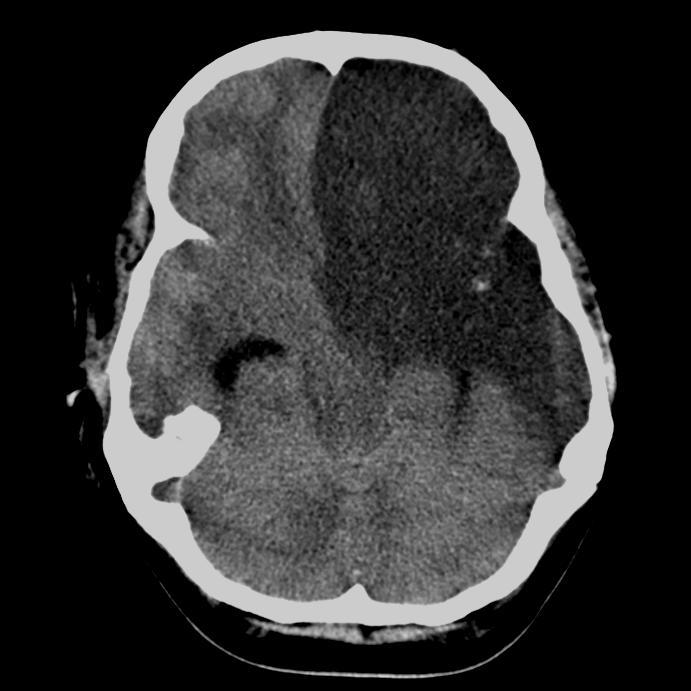
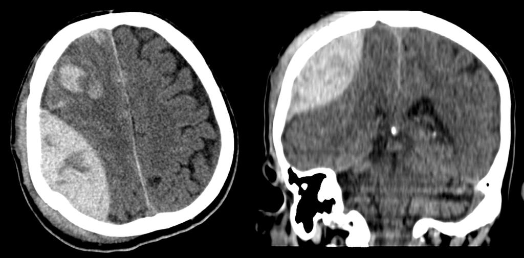
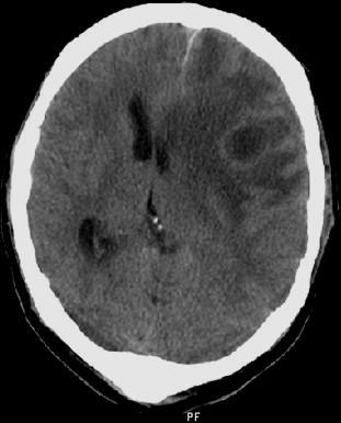
47 CT basic applications 47 brain imaging stroke
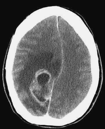
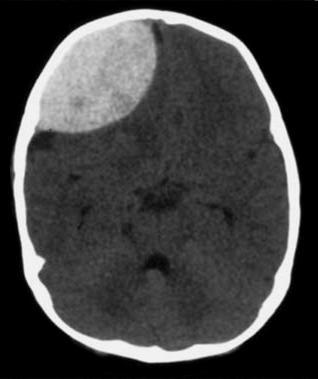
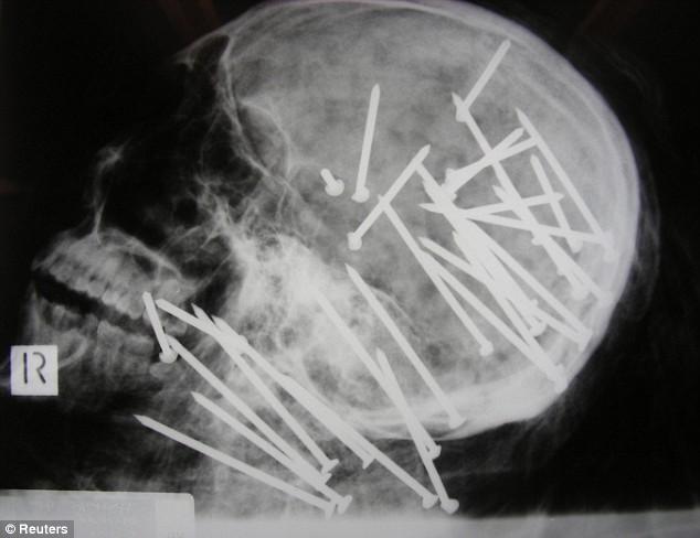
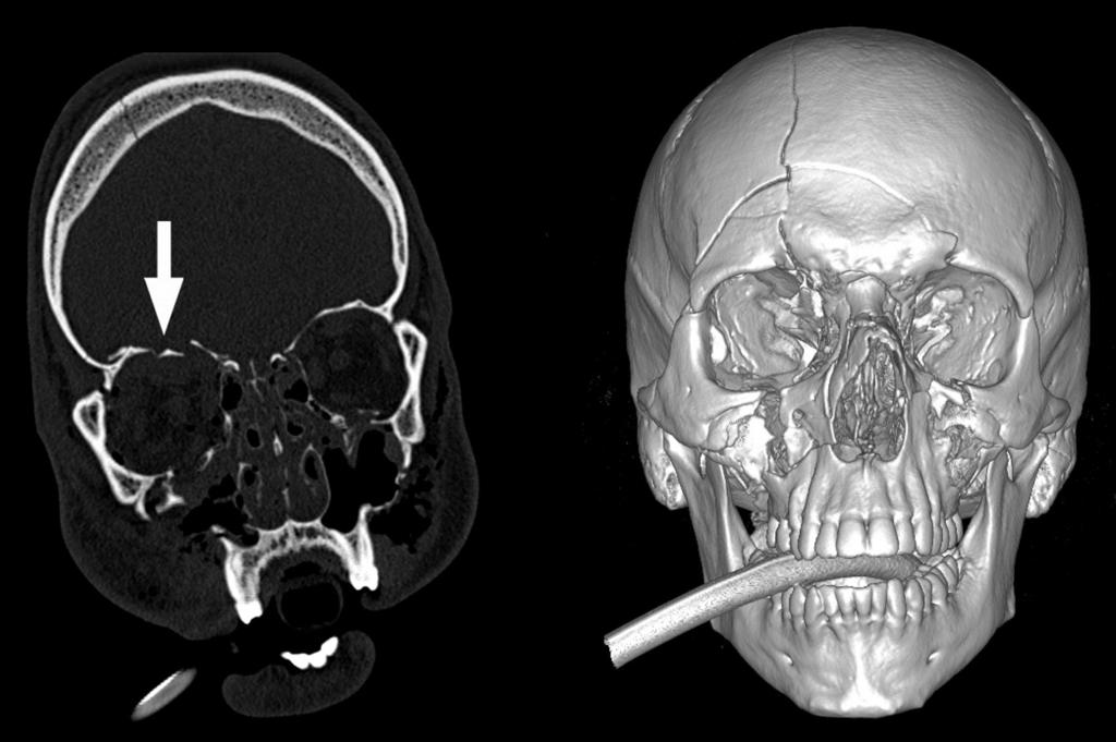
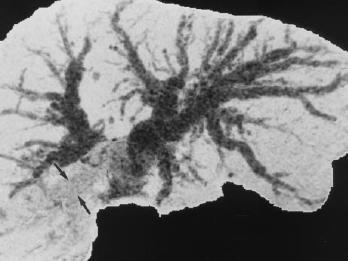
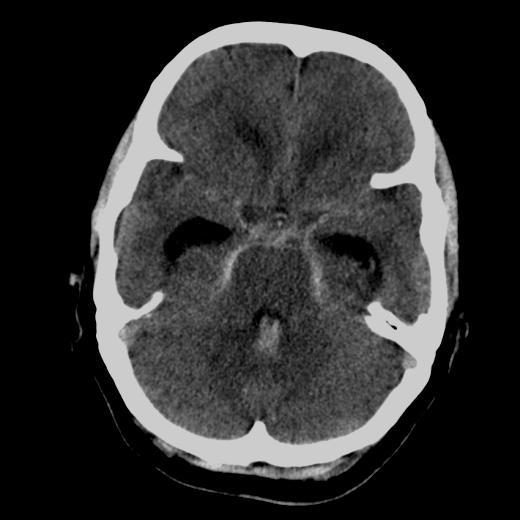
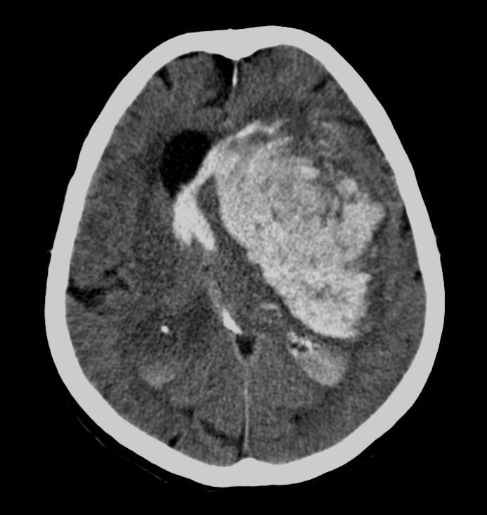
48 CT basic applications 48 brain imaging injury, tumor, infection


49 CT basic applications 49 spine injury, degenarive disease
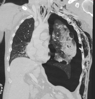
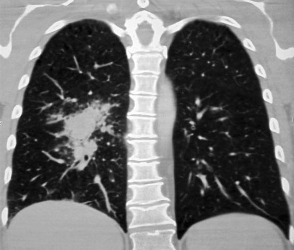
50 CT basic applications 50 chest injury, cancer,
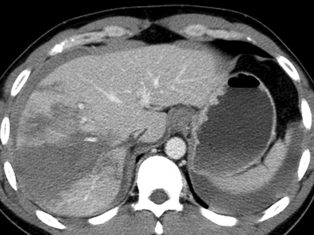
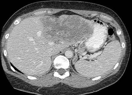
51 CT basic applications 51 abdomen injury, cancer


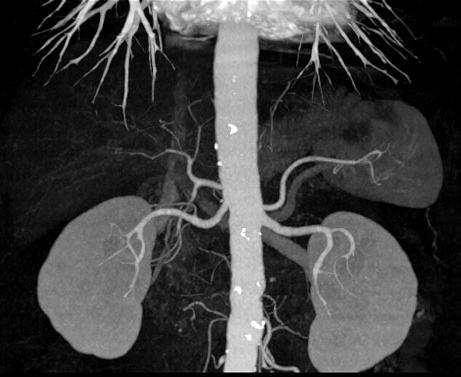
52 CT basic applications 52 vascular imaging aorta, carotids


53 CT basic applications 53 vascular imaging renal graft

54 CT basic applications 54 bone injury
55 CT contraindications 55 contraindications to x-ray imaging to iodinated contrast media inability to hold on the exam (dyspnea, tremor, children) lacking indications
56 CT complications 56 complications x-rays contrast media
57 57 CT advanced applications
58 CT advanced applications 58 perfusion CT perfusion imaging rbf rbv TTP MTT PS

59 59 CT technique

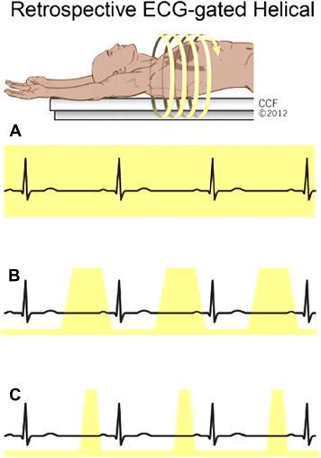
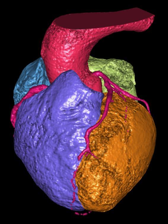
60 CT advanced applications 60 cardiac CT

61 61 CT advanced applications

62 62 CT advanced applications

63 CT advanced applications 63 0% 10% 20% 30% 40% 50% 60% 70% 80% 90%

64 64 CT advanced applications

65 65 CT advanced applications


66 CT advanced applications 66 wall motion wall thickenning ED wall thickness
67 CT advanced applications 67 advances in CT technology wide detector panels z-flying focal spot dual-source CT dual-energy CT PET-CT
68 CT advanced applications 68 advances in CT technology wide detector panels z-flying focal spot dual-source CT dual-energy CT PET-CT

69 CT advanced applications 69 advances in CT technology wide detector panels z-flying focal spot dual-source CT dual-energy CT PET-CT


70 CT advanced applications 70 advances in CT technology wide detector panels z-flying focal spot dual-source CT dual-energy CT PET-CT


71 CT advanced applications 71 advances in CT technology wide detector panels z-flying focal spot dual-source CT dual-energy CT PET-CT


72 CT advanced applications 72 advances in CT technology wide detector panels z-flying focal spot dual-source CT dual-energy CT PET-CT Kalender WA, Computed Tomography, Second Edition, pg. 74,

 used to")
73 CT advanced applications 73 CT fluoroscopy the scanner provides pseudo-real time tomographic images that are most commonly used for guidance during biopsies the CT image is constantly updated to include the latest projection data images are displayed on a monitor in the cine mode low tube currents (20 to 50 ma) used to minimize dose
74 74 CT artifacts
75 CT artifacts 75 CT artifacts physics-based artifacts result from the physical processes involved in the acquisition of CT data patient-based artifacts caused by such factors as patient movement or the presence of metallic materials in or on the patient scanner-based artifacts result from imperfections in scanner function Barrett JF, et al: Artifacts in CT: Recognition and Avoidance. RadioGraphics 2004.

76 CT artifacts 76 physics-based artifacts beam hardening x-ray beam is composed of individual photons with a range of energies. As the beam passes through an object, it becomes harder, that is to say its mean energy increases, because the lower-energy photons are absorbed more rapidly than the higherenergy photons

77 CT artifacts 77 physics-based artifacts partial volume artifacts caused by a mixture of tissues with very different attenuation coefficients within any given voxel, resulting in tissue shading

78 CT artifacts 78 physics-based artifacts photon starvation can occur in highly attenuating areas such as the shoulders. When the x-ray beam is traveling horizontally, the attenuation is greatest and insufficient photons reach the detectors. The result is that very noisy projections are produced at these tube angulations. The reconstruction process has the effect of greatly magnifying the noise, resulting in horizontal streaks in the image.

79 CT artifacts 79 patient-based artifacts metallic artifacts severe streaking artifacts that occur because the density of the metal is beyond the normal range that can be handled by the computer, resulting in incomplete attenuation profiles

80 CT artifacts 80 patient-based artifacts motion artifacts patient motion can cause misregistration artifacts, which usually appear as shading or streaking in the reconstructed image

81 CT artifacts 81 scanner-based artifacts ring artifacts the detector gives a consistently erroneous reading at each angular position when one of the detectors is out of calibration
82 82 CT radiation dose
83 CT radiation dose 83 rationale 1 person / 1000 would develop cancer from 10 msv (abdomen CT) Committee to assess health risks from exposure to low levels of ionizing radiation. Washington DC
84 CT radiation dose 84 basics beam energy kvp vs. low-dose imaging photon fluence radiation dose is directly proportional to the milliampere-seconds value Mc Nitt-Gray MF: AAPM/RSNA Physics Tutorial for Residents: Topics in CT Radiation Dose in CT. RadioGraphics 2002.
85 CT radiation dose 85 basics pitch value (table distance traveled in one 360 rotation/total collimated width of the x-ray beam) has a direct influence on patient radiation dose. As pitch increases, the time that any one point in space spends in the x-ray beam is decreased. beam collimation Mc Nitt-Gray MF: AAPM/RSNA Physics Tutorial for Residents: Topics in CT Radiation Dose in CT. RadioGraphics 2002.
86 CT radiation dose 86 basics patient size when the same technical parameters are used, the appropriate index shows that the smaller object always absorbs the higher dose and that the difference is at least a factor of two z-axis coverage scanner dose-reducing systems (tube current modulation, automatic mas settings, iteative reconstructions) Lee CH, et al.: Radiation Dose Modulation Techniques in the Multidetector CT Era: From Basics to Practice. RadioGraphics 2008.
87 CT radiation dose 87 measures weighted CTDI x-ray beam often passes directly into the entire surface of the patient s body primary x-ray beam contains the most photons and is most attenuated by the patient tissue energy delivered to the patient is higher at the skin surface than in the center of the body, even though the x-ray beams from all the way around the gantry pass through the center of the body.
88 CT radiation dose 88 measures volume CTDI CTDI adjusted for pitch (the gap or overlap of the helical pattern of radiation) = CTDI w divided by the pitch scan with a pitch less than 1 would therefore have a CTDI vol value larger than the CTDI w value scans with a pitch greater than 1 would have a CTDI vol value smaller than the CTDI w value
89 CT radiation dose 89 measures dose-length product DLP is calculated to account for the differences in the scan extent for a CT examination the risk of radiation-induced damage to patient tissues increases with the volume of body scanned DLP is calculated by multiplying CTDI vol in Gy by the scan extent in cm
90 CT radiation dose 90 measures kvp not only controls the image contrast but also controls the amount of penetration that the x-ray beam will have as it traverses the patient 80 kvp 120 kvp 140 kvp image contrast best intermediate poor noise most average least penetration least average most patient dose lowest intermediate highest

91 CT radiation dose 91 measures kvp not only controls the image contrast but also controls the amount of penetration that the x-ray beam will have as it traverses the patient 120 kvp 140 kvp
92 CT radiation dose 92 measures kvp not only controls the image contrast but also controls the amount of penetration that the x-ray beam will have as it traverses the patient mas CTDI w head CTDI w body mgy 6 mgy mgy 12 mgy mgy 18 mgy mgy 23 mgy
93 CT radiation dose 93 doses Lee CH, et al.: Radiation Dose Modulation Techniques in the Multidetector CT Era: From Basics to Practice. RadioGraphics 2008.
94 CT radiation dose 94 recommendations Patient size relative dose more for smaller patients (Am Coll Radiol) pediatric abdomen CT (5 yr old) < 25 mgy adult abdomen CT < 30 mgy FDA notice: for pediatric and small patients reduce tube ma (current) increase pitch develop ma settings based on patient weight or diameter and body region reduce number of multiple scans without contrast eliminate inappropriate referrals for CT
95 CT radiation dose 95 trade-offs decrease ma or current increase noise increase pitch increase volume averaging increase axial increment introduce gaps eff. dose (msv) no. of chest x-rays period of background radiation chest x-ray d mmg mo abdomen x-ray mo chest CT y abdomen CT y
96 CT radiation dose 96 EXERCISE How to reduce the patient dose without decreasing image quality?
Digital Image Processing
 Digital Image Processing SPECIAL TOPICS CT IMAGES Hamid R. Rabiee Fall 2015 What is an image? 2 Are images only about visual concepts? We ve already seen that there are other kinds of image. In this lecture
Optimization of CT Simulation Imaging. Ingrid Reiser Dept. of Radiology The University of Chicago
 Optimization of CT Simulation Imaging Ingrid Reiser Dept. of Radiology The University of Chicago Optimization of CT imaging Goal: Achieve image quality that allows to perform the task at hand (diagnostic
Computed Tomography. Principles, Design, Artifacts, and Recent Advances. Jiang Hsieh THIRD EDITION. SPIE PRESS Bellingham, Washington USA
 Computed Tomography Principles, Design, Artifacts, and Recent Advances THIRD EDITION Jiang Hsieh SPIE PRESS Bellingham, Washington USA Table of Contents Preface Nomenclature and Abbreviations xi xv 1 Introduction
Shadow casting. What is the problem? Cone Beam Computed Tomography THE OBJECTIVES OF DIAGNOSTIC IMAGING IDEAL DIAGNOSTIC IMAGING STUDY LIMITATIONS
 Cone Beam Computed Tomography THE OBJECTIVES OF DIAGNOSTIC IMAGING Reveal pathology Reveal the anatomic truth Steven R. Singer, DDS srs2@columbia.edu IDEAL DIAGNOSTIC IMAGING STUDY Provides desired diagnostic
Corso di laurea in Fisica A.A Fisica Medica 4 TC
 Corso di laurea in Fisica A.A. 2007-2008 Fisica Medica 4 TC Computed Tomography Principles 1. Projection measurement 2. Scanner systems 3. Scanning modes Basic Tomographic Principle The internal structure
Ch. 4 Physical Principles of CT
 Ch. 4 Physical Principles of CT CLRS 408: Intro to CT Department of Radiation Sciences Review: Why CT? Solution for radiography/tomography limitations Superimposition of structures Distinguishing between
A closer look at CT scanning
 Vet Times The website for the veterinary profession https://www.vettimes.co.uk A closer look at CT scanning Author : Charissa Lee, Natalie Webster Categories : General, Vets Date : April 3, 2017 A basic
Computer-Tomography II: Image reconstruction and applications
 Computer-Tomography II: Image reconstruction and applications Prof. Dr. U. Oelfke DKFZ Heidelberg Department of Medical Physics (E040) Im Neuenheimer Feld 280 69120 Heidelberg, Germany u.oelfke@dkfz.de
Some reference material
 Some reference material Physics reference book on medical imaging: A good one is The Essential Physics of Medical Imaging, 3 rd Ed. by Bushberg et al. ($170! new). However, there are several similar books
Image Acquisition Systems
 Image Acquisition Systems Goals and Terminology Conventional Radiography Axial Tomography Computer Axial Tomography (CAT) Magnetic Resonance Imaging (MRI) PET, SPECT Ultrasound Microscopy Imaging ITCS
CLASS HOURS: 4 CREDIT HOURS: 4 LABORATORY HOURS: 0
 Revised 10/10 COURSE SYLLABUS TM 220 COMPUTED TOMOGRAPHY PHYSICS CLASS HOURS: 4 CREDIT HOURS: 4 LABORATORY HOURS: 0 CATALOG COURSE DESCRIPTION: This course is one of a three course set in whole body Computed
CT Basics Principles of Spiral CT Dose. Always Thinking Ahead.
 1 CT Basics Principles of Spiral CT Dose 2 Who invented CT? 1963 - Alan Cormack developed a mathematical method of reconstructing images from x-ray projections Sir Godfrey Hounsfield worked for the Central
Introduction to Biomedical Imaging
 Alejandro Frangi, PhD Computational Imaging Lab Department of Information & Communication Technology Pompeu Fabra University www.cilab.upf.edu X-ray Projection Imaging Computed Tomography Digital X-ray
Spiral CT. Protocol Optimization & Quality Assurance. Ge Wang, Ph.D. Department of Radiology University of Iowa Iowa City, Iowa 52242, USA
 Spiral CT Protocol Optimization & Quality Assurance Ge Wang, Ph.D. Department of Radiology University of Iowa Iowa City, Iowa 52242, USA Spiral CT Protocol Optimization & Quality Assurance Protocol optimization
3/27/2012 WHY SPECT / CT? SPECT / CT Basic Principles. Advantages of SPECT. Advantages of CT. Dr John C. Dickson, Principal Physicist UCLH
 3/27/212 Advantages of SPECT SPECT / CT Basic Principles Dr John C. Dickson, Principal Physicist UCLH Institute of Nuclear Medicine, University College London Hospitals and University College London john.dickson@uclh.nhs.uk
MEDICAL IMAGING 2nd Part Computed Tomography
 MEDICAL IMAGING 2nd Part Computed Tomography Introduction 2 In the last 30 years X-ray Computed Tomography development produced a great change in the role of diagnostic imaging in medicine. In convetional
AIDR 3D Iterative Reconstruction:
 Iterative Reconstruction: Integrated, Automated and Adaptive Dose Reduction Erin Angel, PhD Manager, Clinical Sciences, CT Canon Medical Systems USA Iterative Reconstruction 1 Since the introduction of
MEDICAL EQUIPMENT: COMPUTED TOMOGRAPHY. Prof. Yasser Mostafa Kadah
 MEDICAL EQUIPMENT: COMPUTED TOMOGRAPHY Prof. Yasser Mostafa Kadah www.k-space.org Recommended Textbook X-Ray Computed Tomography in Biomedical Engineering, by Robert Cierniak, Springer, 211 Computed Tomography
Medical Image Processing: Image Reconstruction and 3D Renderings
 Medical Image Processing: Image Reconstruction and 3D Renderings 김보형 서울대학교컴퓨터공학부 Computer Graphics and Image Processing Lab. 2011. 3. 23 1 Computer Graphics & Image Processing Computer Graphics : Create,
Radiology. Marta Anguiano Millán. Departamento de Física Atómica, Molecular y Nuclear Facultad de Ciencias. Universidad de Granada
 Departamento de Física Atómica, Molecular y Nuclear Facultad de Ciencias. Universidad de Granada Overview Introduction Overview Introduction Tecniques of imaging in Overview Introduction Tecniques of imaging
Philips SPECT/CT Systems
 Philips SPECT/CT Systems Ling Shao, PhD Director, Imaging Physics & System Analysis Nuclear Medicine, Philips Healthcare June 14, 2008 *Presented SNM08 Categorical Seminar - Quantitative SPECT and PET
AAPM Standard of Practice: CT Protocol Review Physicist
 AAPM Standard of Practice: CT Protocol Review Physicist Dianna Cody, Ph.D., DABR, FAAPM U.T.M.D. Anderson Cancer Center September 11, 2014 2014 Texas Radiation Regulatory Conference Goals Understand purpose
Multi-slice CT Image Reconstruction Jiang Hsieh, Ph.D.
 Multi-slice CT Image Reconstruction Jiang Hsieh, Ph.D. Applied Science Laboratory, GE Healthcare Technologies 1 Image Generation Reconstruction of images from projections. textbook reconstruction advanced
Metal Artifact Reduction CT Techniques. Tobias Dietrich University Hospital Balgrist University of Zurich Switzerland
 Metal Artifact Reduction CT Techniques R S S S Tobias Dietrich University Hospital Balgrist University of Zurich Switzerland N. 1 v o 4 1 0 2. Postoperative CT Metal Implants CT is accurate for assessment
Biomedical Imaging. Computed Tomography. Patrícia Figueiredo IST
 Biomedical Imaging Computed Tomography Patrícia Figueiredo IST 2013-2014 Overview Basic principles X ray attenuation projection Slice selection and line projections Projection reconstruction Instrumentation
Cardiac Dual Energy CT: Technique
 RSNA 2013, VSCA51-01, Chicago, Dec. 5, 2013 Cardiac Radiology Series Cardiac Dual Energy CT: Technique Willi A. Kalender, Ph.D. Institute of Medical Physics University of Erlangen www.imp.uni-erlangen.de
8/7/2017. Disclosures. MECT Systems Overview and Quantitative Opportunities. Overview. Computed Tomography (CT) CT Numbers. Polyenergetic Acquisition
 CT Numbers. Polyenergetic Acquisition") Quantitative Multi-Energy Computed Tomography: Imaging and Therapy Advancements Disclosures MECT Systems Overview and Quantitative Opportunities The speaker receives research funding from GE Healthcare
Quantitative Multi-Energy Computed Tomography: Imaging and Therapy Advancements Disclosures MECT Systems Overview and Quantitative Opportunities The speaker receives research funding from GE Healthcare
Fundamentals of CT imaging
 SECTION 1 Fundamentals of CT imaging I History In the early 1970s Sir Godfrey Hounsfield s research produced the first clinically useful CT scans. Original scanners took approximately 6 minutes to perform
CT Protocol Review: Practical Tips for the Imaging Physicist Physicist
 CT Protocol Review: Practical Tips for the Imaging Physicist Physicist Dianna Cody, Ph.D., DABR, FAAPM U.T.M.D. Anderson Cancer Center August 8, 2013 AAPM Annual Meeting Goals Understand purpose and importance
Effect of Scattering on the Image. Reducing Compton Scatter with a Grid
 Effect of Scattering on the Image Increasing Compton scattering degrades image. Webb 21 Reducing Compton Scatter with a Grid Grids Parallel (focused at infinity) Linear Focused (see figure) Moving grids
Joint ICTP-TWAS Workshop on Portable X-ray Analytical Instruments for Cultural Heritage. 29 April - 3 May, 2013
 2455-5 Joint ICTP-TWAS Workshop on Portable X-ray Analytical Instruments for Cultural Heritage 29 April - 3 May, 2013 Lecture NoteBasic principles of X-ray Computed Tomography Diego Dreossi Elettra, Trieste
Optimisation of Toshiba Aquilion ONE Volume Imaging
 Optimisation of Toshiba Aquilion ONE Volume Imaging Jane Edwards, RPRSG Royal Free London NHS Foundation Trust Dr Mufudzi Maviki, Plymouth Hospitals NHS Trust Background In 2011/12 Radiology at RFH was
Equipment Specification
 MULTISLICE CT SCANNER ( 16 Slices ) Merk : Hitachi Japan Model : SUPRIA 5 MHU Price : Rp 6.512.360.215,27 No Equipment Specification 1 2 3 Scanner Gantry Object for scanning : Whole body including head
Tomographic Reconstruction
 Tomographic Reconstruction 3D Image Processing Torsten Möller Reading Gonzales + Woods, Chapter 5.11 2 Overview Physics History Reconstruction basic idea Radon transform Fourier-Slice theorem (Parallel-beam)
CT vs. VolumeScope: image quality and dose comparison
 CT vs. VolumeScope: image quality and dose comparison V.N. Vasiliev *a, A.F. Gamaliy **b, M.Yu. Zaytsev b, K.V. Zaytseva ***b a Russian Sci. Center of Roentgenology & Radiology, 86, Profsoyuznaya, Moscow,
ML reconstruction for CT
 ML reconstruction for CT derivation of MLTR rigid motion correction resolution modeling polychromatic ML model dual energy ML model Bruno De Man, Katrien Van Slambrouck, Maarten Depypere, Frederik Maes,
ImPACT. Information Leaflet No. 1: CT Scanner Acceptance Testing
 ImPACT Information Leaflet No. 1: CT Scanner Acceptance Testing Version 1.02, 18/05/01 CONTENTS: 1. SCOPE OF LEAFLET 2. GENERAL PRINCIPLES OF ACCEPTANCE AND COMMISSIONING 2.1 PHANTOMS 2.2 EXPOSURE AND
Solid Capabilities Are Built Into the Supria Plus. Putting You On The Path of High Quality, Cost-Effective CT Scanning
 Specification Data Putting You On The Path of High Quality, Cost-Effective CT Scanning Solid Capabilities Are Built Into the Supria Plus Addressing the challenges of controlling healthcare organization
MEDICAL IMAGING 2nd Part Computed Tomography
 MEDICAL IMAGING 2nd Part Computed Tomography Introduction 2 In the last 30 years X-ray Computed Tomography development produced a great change in the role of diagnostic imaging in medicine. In convetional
INTERNATIONAL STANDARD
 INTERNATIONAL STANDARD IEC 60601-2-44 2001 AMENDMENT 1 2002-09 Amendment 1 Medical electrical equipment Part 2-44: Particular requirements for the safety of X-ray equipment for computed tomography Amendement
LAB DEMONSTRATION COMPUTED TOMOGRAPHY USING DESKCAT Lab Manual: 0
 LAB DEMONSTRATION COMPUTED TOMOGRAPHY USING DESKCAT Lab Manual: 0 Introduction This lab demonstration explores the physics and technology of Computed Tomography (CT) and guides the student and instructor
Fits you like no other
 Fits you like no other BrightView X and XCT specifications The new BrightView X system is a fully featured variableangle camera that is field-upgradeable to BrightView XCT without any increase in room
CT: Physics Principles & Equipment Design
 CT: Physics Principles & Equipment Design James Kofler, Ph.D Radiology Mayo Clinic Rochester, MN June 27, 2012 Disclosures Nothing to disclose Learning Objectives Understand fundamental concepts of - CT
The Near Future in Cardiac CT Image Reconstruction
 SCCT 2010 The Near Future in Cardiac CT Image Reconstruction Marc Kachelrieß Institute of Medical Physics (IMP) Friedrich-Alexander Alexander-University Erlangen-Nürnberg rnberg www.imp.uni-erlangen.de
ImPACT. CT dosimetry and a data base for CTDI values. EFOMP Workshop at ECR Imaging Performance Assessment of CT Scanners
 ImPACT Imaging Performance Assessment of CT Scanners A Medical Devices Agency Evaluation Group CT dosimetry and a data base for CTDI values EFOMP Workshop at ECR 2002 S. Edyvean, ImPACT St George s Hospital,
Background. Outline. Radiographic Tomosynthesis: Image Quality and Artifacts Reduction 1 / GE /
 Radiographic Tomosynthesis: Image Quality and Artifacts Reduction Baojun Li, Ph.D Department of Radiology Boston University Medical Center 2012 AAPM Annual Meeting Background Linear Trajectory Tomosynthesis
Fujifilm DR Solution. FDR AcSelerate. The new pinnacle in diagnostic imaging from Fujifilm ISS. CsI. Dynamic Visualization. Technology.
 Fujifilm DR Solution FDR AcSelerate The new pinnacle in diagnostic imaging from Fujifilm CsI Scintillator ISS Technology Dynamic Visualization Welcome to the X-ray room of the future! A streamlined solution
Design and performance characteristics of a Cone Beam CT system for Leksell Gamma Knife Icon
 Design and performance characteristics of a Cone Beam CT system for Leksell Gamma Knife Icon WHITE PAPER Introduction Introducing an image guidance system based on Cone Beam CT (CBCT) and a mask immobilization
BME I5000: Biomedical Imaging
 1 Lucas Parra, CCNY BME I5000: Biomedical Imaging Lecture 4 Computed Tomography Lucas C. Parra, parra@ccny.cuny.edu some slides inspired by lecture notes of Andreas H. Hilscher at Columbia University.
Brilliance CT Big Bore.
 1 2 2 There are two methods of RCCT acquisition in widespread clinical use: cine axial and helical. In RCCT with cine axial acquisition, repeat CT images are taken each couch position while recording respiration.
CT Basics: Image Processing and Reconstruction Module 4
 Module 4 For educational and institutional use. This transcript is licensed for noncommercial, educational inhouse or online educational course use only in educational and corporate institutions. Any broadcast,
[PDR03] RECOMMENDED CT-SCAN PROTOCOLS
![[PDR03] RECOMMENDED CT-SCAN PROTOCOLS](/thumbs/72/66454100.jpg "[PDR03] RECOMMENDED CT-SCAN PROTOCOLS") SURGICAL & PROSTHETIC DESIGN [PDR03] RECOMMENDED CT-SCAN PROTOCOLS WORK-INSTRUCTIONS DOCUMENT (CUSTOMER) RECOMMENDED CT-SCAN PROTOCOLS [PDR03_V1]: LIVE 1 PRESCRIBING SURGEONS Patient-specific implants,
SURGICAL & PROSTHETIC DESIGN [PDR03] RECOMMENDED CT-SCAN PROTOCOLS WORK-INSTRUCTIONS DOCUMENT (CUSTOMER) RECOMMENDED CT-SCAN PROTOCOLS [PDR03_V1]: LIVE 1 PRESCRIBING SURGEONS Patient-specific implants,
Computational Medical Imaging Analysis Chapter 4: Image Visualization
 Computational Medical Imaging Analysis Chapter 4: Image Visualization Jun Zhang Laboratory for Computational Medical Imaging & Data Analysis Department of Computer Science University of Kentucky Lexington,
Interaction map. X-Ray Computed Tomography Measures Tissue Properties from Macro to Micro. Outline
 X-Ray Computed Tomography Measures Tissue Properties from Macro to Micro Michael Andre, Ph.D. Department of Radiology University of California, San Diego San Diego VA Healthcare System Outline Perspective
PRODUCT DATA. Advanced 128
 PRODUCT DATA Advanced 128 Supria 16 Slice CT Puts You On The Path of High Quality, Cost-Effective CT Scanning Solid Capabilities Are Built Into the Supria Addressing the challenges of controlling healthcare
icatvision Quick Reference
 icatvision Quick Reference Navigating the i-cat Interface This guide shows how to: View reconstructed images Use main features and tools to optimize an image. REMINDER Images are displayed as if you are
CT NOISE POWER SPECTRUM FOR FILTERED BACKPROJECTION AND ITERATIVE RECONSTRUCTION
 CT NOISE POWER SPECTRUM FOR FILTERED BACKPROJECTION AND ITERATIVE RECONSTRUCTION Frank Dong, PhD, DABR Diagnostic Physicist, Imaging Institute Cleveland Clinic Foundation and Associate Professor of Radiology
DUAL energy X-ray radiography [1] can be used to separate
![DUAL energy X-ray radiography [1] can be used to separate](/thumbs/91/106229592.jpg "DUAL energy X-ray radiography [1] can be used to separate") IEEE TRANSACTIONS ON NUCLEAR SCIENCE, VOL. 53, NO. 1, FEBRUARY 2006 133 A Scatter Correction Using Thickness Iteration in Dual-Energy Radiography S. K. Ahn, G. Cho, and H. Jeon Abstract In dual-energy
IEEE TRANSACTIONS ON NUCLEAR SCIENCE, VOL. 53, NO. 1, FEBRUARY 2006 133 A Scatter Correction Using Thickness Iteration in Dual-Energy Radiography S. K. Ahn, G. Cho, and H. Jeon Abstract In dual-energy
Spectral analysis of non-stationary CT noise
 Spectral analysis of non-stationary CT noise Kenneth M. Hanson Los Alamos Scientific Laboratory Int. Symposium and Course on Computed Tomography, Las Vegas, April 7-11, 1980 This presentation available
FINDING THE TRUE EDGE IN CTA
 FINDING THE TRUE EDGE IN CTA by: John A. Rumberger, PhD, MD, FACC Your patient has chest pain. The Cardiac CT Angiography shows plaque in the LAD. You adjust the viewing window trying to evaluate the stenosis
Scatter Correction for Dual source Cone beam CT Using the Pre patient Grid. Yingxuan Chen. Graduate Program in Medical Physics Duke University
 Scatter Correction for Dual source Cone beam CT Using the Pre patient Grid by Yingxuan Chen Graduate Program in Medical Physics Duke University Date: Approved: Lei Ren, Supervisor Fang Fang Yin, Chair
Computed Tomography Imaging: CT Protocol Management. Caveat 8/3/2017
 Computed Tomography Imaging: CT Protocol Management Mark P. Supanich, Ph.D., DABR AAPM Annual Meeting 3 rd August, 2017 Slides at: goo.gl/k8n8jf Rush is an academic health system comprising Rush University
Fits you like no other
 Fits you like no other Philips BrightView X and XCT specifications The new BrightView X system is a fully featured variableangle camera that is field-upgradeable to BrightView XCT without any increase
Financial disclosure. Onboard imaging modality for IGRT
 Tetrahedron Beam Computed Tomography Based On Multi-Pixel X- Ray Source and Its Application in Image Guided Radiotherapy Tiezhi Zhang, Ph.D. Advanced X-ray imaging Lab Financial disclosure Patent royalty
Application of 450 kv Computed Tomography to Engine Blocks with Steel Liners
 Application of 450 kv Computed Tomography to Engine Blocks with Steel Liners Charles R. Smith, Kevin Holt BIR, Inc. Uwe Bischoff, Bernd Georgi, Ferdinand Hansen, Frank Jeltsch Volkswagen Commercial Vehicles
Simulation of Mammograms & Tomosynthesis imaging with Cone Beam Breast CT images
 Simulation of Mammograms & Tomosynthesis imaging with Cone Beam Breast CT images Tao Han, Chris C. Shaw, Lingyun Chen, Chao-jen Lai, Xinming Liu, Tianpeng Wang Digital Imaging Research Laboratory (DIRL),
Carestream s 2 nd Generation Metal Artifact Reduction Software (CMAR 2)
") Carestream s 2 nd Generation Metal Artifact Reduction Software (CMAR 2) Author: Levon Vogelsang Introduction Cone beam computed tomography (CBCT), or cone beam CT technology, offers considerable promise
Carestream s 2 nd Generation Metal Artifact Reduction Software (CMAR 2) Author: Levon Vogelsang Introduction Cone beam computed tomography (CBCT), or cone beam CT technology, offers considerable promise
Medical Imaging BMEN Spring 2016
 Name Medical Imaging BMEN 420-501 Spring 2016 Homework #4 and Nuclear Medicine Notes All questions are from the introductory Powerpoint (based on Chapter 7) and text Medical Imaging Signals and Systems,
Micro-CT Methodology Hasan Alsaid, PhD
 Micro-CT Methodology Hasan Alsaid, PhD Preclinical & Translational Imaging LAS, PTS, GlaxoSmithKline 20 April 2015 Provide basic understanding of technical aspects of the micro-ct Statement: All procedures
X-ray Computed Tomography: Principle and Recent Advancements
 X-ray Computed Tomography: Principle and Recent Advancements Jiang Hsieh, Ph.D. GE Medical Systems, Milwaukee, WI Jiang Hsieh SPIE MI 2003 Course Note 1 Principle and Recent Advancements in X-ray Computed
Reduction of Metal Artifacts in Computed Tomographies for the Planning and Simulation of Radiation Therapy
 Reduction of Metal Artifacts in Computed Tomographies for the Planning and Simulation of Radiation Therapy T. Rohlfing a, D. Zerfowski b, J. Beier a, P. Wust a, N. Hosten a, R. Felix a a Department of
Digital Scatter Removal in Mammography to enable Patient Dose Reduction
 Digital Scatter Removal in Mammography to enable Patient Dose Reduction Mary Cocker Radiation Physics and Protection Oxford University Hospitals NHS Trust Chris Tromans, Mike Brady University of Oxford
Empirical cupping correction: A first-order raw data precorrection for cone-beam computed tomography
 Empirical cupping correction: A first-order raw data precorrection for cone-beam computed tomography Marc Kachelrieß, a Katia Sourbelle, and Willi A. Kalender Institute of Medical Physics, University of
Modifications for P551 Fall 2014
 LAB DEMONSTRATION COMPUTED TOMOGRAPHY USING DESKCAT 1 Modifications for P551 Fall 2014 Introduction This lab demonstration explores the physics and technology of Computed Tomography (CT) and guides the
O-ARM IMAGING SYSTEM TECHNICAL SPECIFICATION GUIDE
 IMAGING SYSTEM TECHNICAL SPECIFICATION GUIDE SYSTEM FEATURES CATEGORY PHYSICAL DIMENSIONS IMAGING MODALITY PERFORMANCE SPECIFICATION Length Width Height Weight Gantry Opening Bore Diameter Single Plane
First CT Scanner. How it Works. Contemporary CT. Before and After CT. Computer Tomography: How It Works. Medical Imaging and Pattern Recognition
 Computer Tomography: How t Works Medical maging and Pattern Recognition Lecture 7 Computed Tomography Oleh Tretiak Only one plane is illuminated. Source-subject motion provides added information. 2 How
Computed Tomography. Principles of Medical Imaging. Contents. Prof. Dr. Philippe Cattin. MIAC, University of Basel. Sep 26th/Oct 3rd, 2016
 Computed Tomography Principles of Medical Imaging Prof. Dr. Philippe Cattin MIAC, University of Basel Contents Abstract 1 Computed Tomography Basics Introduction Computed Tomography Hounsfield's CT Prototype
PURE. ViSION Edition PET/CT. Patient Comfort Put First.
 PURE ViSION Edition PET/CT Patient Comfort Put First. 2 System features that put patient comfort and safety first. Oncology patients deserve the highest levels of safety and comfort during scans. Our Celesteion
GPU implementation for rapid iterative image reconstruction algorithm
 GPU implementation for rapid iterative image reconstruction algorithm and its applications in nuclear medicine Jakub Pietrzak Krzysztof Kacperski Department of Medical Physics, Maria Skłodowska-Curie Memorial
DUE to beam polychromacity in CT and the energy dependence
 1 Empirical Water Precorrection for Cone-Beam Computed Tomography Katia Sourbelle, Marc Kachelrieß, Member, IEEE, and Willi A. Kalender Abstract We propose an algorithm to correct for the cupping artifact
Computer-Tomography I: Principles, History, Technology
 Computer-Tomography I: Principles, History, Technology Prof. Dr. U. Oelfke DKFZ Heidelberg Department of Medical Physics (E040) Im Neuenheimer Feld 280 69120 Heidelberg, Germany u.oelfke@dkfz.de History
INTRODUCTION TO MEDICAL IMAGING- 3D LOCALIZATION LAB MANUAL 1. Modifications for P551 Fall 2013 Medical Physics Laboratory
 INTRODUCTION TO MEDICAL IMAGING- 3D LOCALIZATION LAB MANUAL 1 Modifications for P551 Fall 2013 Medical Physics Laboratory Introduction Following the introductory lab 0, this lab exercise the student through
Dose Distributions. Purpose. Isodose distributions. To familiarize the resident with dose distributions and the factors that affect them
 Dose Distributions George Starkschall, Ph.D. Department of Radiation Physics U.T. M.D. Anderson Cancer Center Purpose To familiarize the resident with dose distributions and the factors that affect them
Annexure XII SPECIFICATIONS FOR A NEW STATE OF ART 16 SLICE ALL PURPOSE C. T. SCANNER
 Annexure XII SPECIFICATIONS FOR A NEW STATE OF ART 16 SLICE ALL PURPOSE C. T. SCANNER A) Scanner Design X-Ray generator and tube: 1. Scanner: Whole body spiral CT scanner (16 slices) of latest technology.
Assessment of 3D performance metrics. X-ray based Volumetric imaging systems: Fourier-based imaging metrics. The MTF in CT
 Assessment of 3D performance metrics D and 3D Metrics of Performance Towards Quality Index: Volumetric imaging systems X-ray based Volumetric imaging systems: CBCT/CT Tomosynthesis Samuel Richard and Ehsan
Artifacts in Spiral X-ray CT Scanners: Problems and Solutions
 Artifacts in Spiral X-ray CT Scanners: Problems and Solutions Mehran Yazdi, and Luc Beaulieu International Science Index, Electrical and Computer Engineering waset.org/publication/12966 Abstract Artifact
C a t p h a n / T h e P h a n t o m L a b o r a t o r y
 C a t p h a n 5 0 0 / 6 0 0 T h e P h a n t o m L a b o r a t o r y C a t p h a n 5 0 0 / 6 0 0 Internationally recognized for measuring the maximum obtainable performance of axial, spiral and multi-slice
1970 Projection Radiography 2D projection of 3D anatomy
 Speakers: L. N. Rothenberg, Ph.D. Computed Tomography G. D. Clarke, Ph.D. Magnetic Resonance Imaging J. A. Zagzebski, Ph.D. Ultrasonic Imaging August 1, 2012 Lawrence N. Rothenberg, Ph.D. Keith S. Pentlow,
Improvement of Efficiency and Flexibility in Multi-slice Helical CT
 J. Shanghai Jiaotong Univ. (Sci.), 2008, 13(4): 408 412 DOI: 10.1007/s12204-008-0408-x Improvement of Efficiency and Flexibility in Multi-slice Helical CT SUN Wen-wu 1 ( ), CHEN Si-ping 2 ( ), ZHUANG Tian-ge
Introduction to Positron Emission Tomography
 Planar and SPECT Cameras Summary Introduction to Positron Emission Tomography, Ph.D. Nuclear Medicine Basic Science Lectures srbowen@uw.edu System components: Collimator Detector Electronics Collimator
4/19/2016. Deborah Thames R.T. (R)(M)(QM) Theory & Technology and advancement in 3D imaging DBT
(M)(QM) Theory & Technology and advancement in 3D imaging DBT") Deborah Thames R.T. (R)(M)(QM) Theory & Technology and advancement in 3D imaging DBT 1 Three manufacturers approved for Tomo Hologic and GE, and Siemens Why 2D Digital Mammography 2D FFDM it appears to
Deborah Thames R.T. (R)(M)(QM) Theory & Technology and advancement in 3D imaging DBT 1 Three manufacturers approved for Tomo Hologic and GE, and Siemens Why 2D Digital Mammography 2D FFDM it appears to
Corso di laurea in Fisica A.A Fisica Medica 5 SPECT, PET
 Corso di laurea in Fisica A.A. 2007-2008 Fisica Medica 5 SPECT, PET Step 1: Inject Patient with Radioactive Drug Drug is labeled with positron (β + ) emitting radionuclide. Drug localizes
Basics of treatment planning II
 Basics of treatment planning II Sastry Vedam PhD DABR Introduction to Medical Physics III: Therapy Spring 2015 Dose calculation algorithms! Correction based! Model based 1 Dose calculation algorithms!
Lecture 6: Medical imaging and image-guided interventions
 ME 328: Medical Robotics Winter 2019 Lecture 6: Medical imaging and image-guided interventions Allison Okamura Stanford University Updates Assignment 3 Due this Thursday, Jan. 31 Note that this assignment
The effects of metal on size specific dose estimation (SSDE) in CT : a phantom study
 in CT : a phantom study") The University of Toledo The University of Toledo Digital Repository Theses and Dissertations 2016 The effects of metal on size specific dose estimation (SSDE) in CT : a phantom study Maram M. Alsanea
The University of Toledo The University of Toledo Digital Repository Theses and Dissertations 2016 The effects of metal on size specific dose estimation (SSDE) in CT : a phantom study Maram M. Alsanea
Diagnostic imaging techniques. Krasznai Zoltán. University of Debrecen Medical and Health Science Centre Department of Biophysics and Cell Biology
 Diagnostic imaging techniques Krasznai Zoltán University of Debrecen Medical and Health Science Centre Department of Biophysics and Cell Biology 1. Computer tomography (CT) 2. Gamma camera 3. Single Photon
SCENARIA 64-Slice CT Putting Advanced CT Within Reach.
 SCENARIA 64-Slice CT Putting Advanced CT Within Reach. Advancing the technology of Computed Tomography for over 30 years, Hitachi is a recognized innovator of lower dose*, high diagnostic value CT solutions.
MDCT and 3D Workstations
 MDCT and 3D Workstations Scott A. Lipson, MD Associate Director of Imaging, Long Beach Memorial Medical Center, Long Beach, California MDCT and 3D Workstations A Practical How-To Guide and Teaching File
Computational Medical Imaging Analysis
 Computational Medical Imaging Analysis Chapter 2: Image Acquisition Systems Jun Zhang Laboratory for Computational Medical Imaging & Data Analysis Department of Computer Science University of Kentucky
As fl exible as your care requires
 As fl exible as your care requires Philips Ingenuity Flex 32 CT Built on Ingenuity The Philips Ingenuity Flex 32 helps you provide excellent care with outstanding flexibility, now and in the future. Built