Full-field optical methods for mechanical engineering: essential concepts to find one way
|
|
|
- Felix Barton
- 6 years ago
- Views:
Transcription
1 Full-field optical methods for mechanical engineering: essential concepts to find one way Yves Surrel Techlab September
2 Contents 1 Introduction 3 2 White light methods Random encoding Carrier modulation encoding Examples: displacement measurements Examples: slope measurements Shape measurement Discussion Interferometric methods Light-surface interactions Synthetic sensitivity vectors Different types of interferometry Reference beam and test beam Two test beams at the same point with different sensitivity vectors Two laterally shifted beams Summary 34 5 Conclusion 37 2
3 1 Introduction Large variety of techniques. Terminology issue (structured light, fringe projection, electronic speckle pattern interferometry, shearography, TV holography...). Some keys for a systematic sorting: white light or laser light; nature of information encoding (carrier, random) light/surface interaction (reflection,diffraction,diffusion) interfering beams Surface techniques 3
4 1 Introduction Large variety of techniques. Terminology issue (structured light, fringe projection, electronic speckle pattern interferometry, shearography, TV holography...). Some keys for a systematic sorting: white light or laser light; nature of information encoding (carrier, random) light/surface interaction (reflection,diffraction,diffusion) interfering beams Surface techniques 3
5 1 Introduction Large variety of techniques. Terminology issue (structured light, fringe projection, electronic speckle pattern interferometry, shearography, TV holography...). Some keys for a systematic sorting: white light or laser light; nature of information encoding (carrier, random) light/surface interaction (reflection,diffraction,diffusion) interfering beams Surface techniques 3
6 1 Introduction Large variety of techniques. Terminology issue (structured light, fringe projection, electronic speckle pattern interferometry, shearography, TV holography...). Some keys for a systematic sorting: white light or laser light; nature of information encoding (carrier, random) light/surface interaction (reflection,diffraction,diffusion) interfering beams Surface techniques 3
7 1 Introduction Large variety of techniques. Terminology issue (structured light, fringe projection, electronic speckle pattern interferometry, shearography, TV holography...). Some keys for a systematic sorting: white light or laser light; nature of information encoding (carrier, random) light/surface interaction (reflection,diffraction,diffusion) interfering beams Surface techniques 3
8 1 Introduction Large variety of techniques. Terminology issue (structured light, fringe projection, electronic speckle pattern interferometry, shearography, TV holography...). Some keys for a systematic sorting: white light or laser light; nature of information encoding (carrier, random) light/surface interaction (reflection,diffraction,diffusion) interfering beams Surface techniques 3
9 1 Introduction Large variety of techniques. Terminology issue (structured light, fringe projection, electronic speckle pattern interferometry, shearography, TV holography...). Some keys for a systematic sorting: white light or laser light; nature of information encoding (carrier, random) light/surface interaction (reflection,diffraction,diffusion) interfering beams Surface techniques 3
10 1 Introduction Large variety of techniques. Terminology issue (structured light, fringe projection, electronic speckle pattern interferometry, shearography, TV holography...). Some keys for a systematic sorting: white light or laser light; nature of information encoding (carrier, random) light/surface interaction (reflection,diffraction,diffusion) interfering beams Surface techniques 3
11 2 White light methods Comptest 2004 Bristol Can often be called geometrical methods (optics are generally restricted to image formation). Physical phenomena allowing the measurement are geometrical: deformation of a surface pattern, triangulation etc 2.1 Random encoding A random pattern (local signature) will allow to match pairs of points between the initial and final stages: there is no quantitative information. digital image correlation for displacement measurments; stereocorrelation ( stereophotogrammetry; principle is the same, only implementation is different) : 2 cameras + triangulation = mesure 3D; speckle intensity correlation (the speckle is the signal) 4
12 2 White light methods Comptest 2004 Bristol Can often be called geometrical methods (optics are generally restricted to image formation). Physical phenomena allowing the measurement are geometrical: deformation of a surface pattern, triangulation etc 2.1 Random encoding A random pattern (local signature) will allow to match pairs of points between the initial and final stages: there is no quantitative information. digital image correlation for displacement measurments; stereocorrelation ( stereophotogrammetry; principle is the same, only implementation is different) : 2 cameras + triangulation = mesure 3D; speckle intensity correlation (the speckle is the signal) 4
13 2 White light methods Can often be called geometrical methods (optics are generally restricted to image formation). Physical phenomena allowing the measurement are geometrical: deformation of a surface pattern, triangulation etc 2.1 Random encoding A random pattern (local signature) will allow to match pairs of points between the initial and final stages: there is no quantitative information. digital image correlation for displacement measurments; stereocorrelation ( stereophotogrammetry; principle is the same, only implementation is different) : 2 cameras + triangulation = mesure 3D; speckle intensity correlation (the speckle is the signal) 4
14 Figure 1: Speckle pattern 5
15 Possible random pattern markings: the material itself can be textured by itself heterogeneous materials, fabrics, microstructures, rugosity); the surface must be marked: light paint spray or laser light speckle; in both preceding cases, the pattern is attached to the surface: 3D displacements can be measured; the diffusive surface can be immersed in a coding volume (e.g. videoprojector displaying a random pattern); only shape and shape variation can be measured; 6
16 Possible random pattern markings: the material itself can be textured by itself heterogeneous materials, fabrics, microstructures, rugosity); the surface must be marked: light paint spray or laser light speckle; in both preceding cases, the pattern is attached to the surface: 3D displacements can be measured; the diffusive surface can be immersed in a coding volume (e.g. videoprojector displaying a random pattern); only shape and shape variation can be measured; 6
17 Possible random pattern markings: the material itself can be textured by itself heterogeneous materials, fabrics, microstructures, rugosity); the surface must be marked: light paint spray or laser light speckle; in both preceding cases, the pattern is attached to the surface: 3D displacements can be measured; the diffusive surface can be immersed in a coding volume (e.g. videoprojector displaying a random pattern); only shape and shape variation can be measured; 6
18 Possible random pattern markings: the material itself can be textured by itself heterogeneous materials, fabrics, microstructures, rugosity); the surface must be marked: light paint spray or laser light speckle; in both preceding cases, the pattern is attached to the surface: 3D displacements can be measured; the diffusive surface can be immersed in a coding volume (e.g. videoprojector displaying a random pattern); only shape and shape variation can be measured; 6
19 2.2 Carrier modulation encoding The information is in the phase modulation of a temporal or spatial carrier: it is a quantitative information. The measurand is related (linearly or not) to the phase. Phase-stepping methods are routine. Less than 2π/500 resolution is common. Displacement measurement: grid method ; moiré: add-on to the grid method: frequency shift through a beat between grids; shape measurement: 2 cameras + triangulation; = 3D measurement; deflectometry: measurement of displacements in the reflected image of a grid: measurement of local slopes. 7
20 2.2 Carrier modulation encoding The information is in the phase modulation of a temporal or spatial carrier: it is a quantitative information. The measurand is related (linearly or not) to the phase. Phase-stepping methods are routine. Less than 2π/500 resolution is common. Displacement measurement: grid method ; moiré: add-on to the grid method: frequency shift through a beat between grids; shape measurement: 2 cameras + triangulation; = 3D measurement; deflectometry: measurement of displacements in the reflected image of a grid: measurement of local slopes. 7
21 2.2 Carrier modulation encoding The information is in the phase modulation of a temporal or spatial carrier: it is a quantitative information. The measurand is related (linearly or not) to the phase. Phase-stepping methods are routine. Less than 2π/500 resolution is common. Displacement measurement: grid method ; moiré: add-on to the grid method: frequency shift through a beat between grids; shape measurement: 2 cameras + triangulation; = 3D measurement; deflectometry: measurement of displacements in the reflected image of a grid: measurement of local slopes. 7
22 2.2 Carrier modulation encoding The information is in the phase modulation of a temporal or spatial carrier: it is a quantitative information. The measurand is related (linearly or not) to the phase. Phase-stepping methods are routine. Less than 2π/500 resolution is common. Displacement measurement: grid method ; moiré: add-on to the grid method: frequency shift through a beat between grids; shape measurement: 2 cameras + triangulation; = 3D measurement; deflectometry: measurement of displacements in the reflected image of a grid: measurement of local slopes. 7

23 2.2.1 Examples: displacement measurements Figure 2: Distorsion of a grid: frequency or phase modulation 8
24 Figure 3: Moiré fringes 9
.")

25 (a)...the moiré pattern (b)...the grid Figure 4: Phase maps obtained from... 10
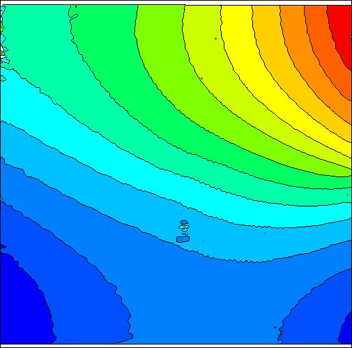
26 theoretical direction of isodisplacement lines fibre direction Displacement (µm) Without end-tabs With [±45] s glass/epoxy end-tabs With oblique end-tabs Figure 5: Off-axis tensile test on a unidirectional graphite/epoxy composite; p = 610 µm. Resolution evaluated from the noise amount: 2π/500 or 1.2 µm. Axial displacement. 11
. 4-point bending.")
27 Déplacements (µm) Figure 6: Crack propagation in reinforced concrete (100 mm 100 mm area, p = 500 µm). 4-point bending. Horizontal displacement 12
28 2.2.2 Examples: slope measurements Comptest 2004 Bristol caméra caméra grille O Q P h z h M α x x plaque masse M support h 2α x Ω Ω P (a) Principle (b) Image rotation Figure 7: Deflectometry 13
29 PMMA plate loading conditions: 1 3 B C A 2 Figure 8: Loading of the plate: simple support at points 1, 2 and 3, and mass suspension at points A, B or C (90.9 g) 14
 φ y, A")
 φ")
 φ x, A")
 φ x, A")


30 (a) φ x, A (b) φ y, A (c) φ x, A + C (d) φ y, A + C (e) φ x, A (f) φ y, A (g) φ x, A + C (h) φ y, A + C Figure 9: Wrapped and unwrapped phase maps, proportional to slopes 15

 (a) xx-curvature (b) yy-curvature")
31 Curvature (km 1 ) Curvature (km 1 ) (a) xx-curvature (b) yy-curvature Figure 10: Curvatures; loading at point A 16

 yx-curvature (c)")
 Figure 11:")
32 (km 1 ) Curvature (a) xy-curvature (b) yx-curvature (c) Deviation (σ = 1.25 km 1 ) Figure 11: Curvatures; loading at point A 17
33 2.2.3 Shape measurement M 1 C 1 M C 2 M 2 Figure 12: Shape measurement using stereocorrelation or fringe projection stereocorrelation: qualitative information go from M to M 1 and M 2 ; given any M 1, the software must find the matching M 2 ; fringe projection: quantitative information go from M 1 to M, then from M to M 2. The (unwrapped) phase value gives the matching. 18
34 2.2.3 Shape measurement M 1 C 1 M C 2 M 2 Figure 12: Shape measurement using stereocorrelation or fringe projection stereocorrelation: qualitative information go from M to M 1 and M 2 ; given any M 1, the software must find the matching M 2 ; fringe projection: quantitative information go from M 1 to M, then from M to M 2. The (unwrapped) phase value gives the matching. 18
35 2.3 Discussion Comptest 2004 Bristol most techniques exist under both dual implementations (periodic, random); their names should be related; performances are better with a periodic encoding (efficient phase detection); better to use a single frequency carrier than to use noise; typical: 1/50 pixel resolution (provable), 5 pixels spatial resolution (carrier); 1/50 pixel resolution (questionable), 32 pixels spatial resolution; carriers are easier to characterize (frequency, amplitude, SNR) than random patterns... carrier-based methods: more difficult, more expensive; problem with periodic carriers: periodic information (phase unwrapping may be necessary; nontrivial problem). 19
36 2.3 Discussion Comptest 2004 Bristol most techniques exist under both dual implementations (periodic, random); their names should be related; performances are better with a periodic encoding (efficient phase detection); better to use a single frequency carrier than to use noise; typical: 1/50 pixel resolution (provable), 5 pixels spatial resolution (carrier); 1/50 pixel resolution (questionable), 32 pixels spatial resolution; carriers are easier to characterize (frequency, amplitude, SNR) than random patterns... carrier-based methods: more difficult, more expensive; problem with periodic carriers: periodic information (phase unwrapping may be necessary; nontrivial problem). 19
37 2.3 Discussion Comptest 2004 Bristol most techniques exist under both dual implementations (periodic, random); their names should be related; performances are better with a periodic encoding (efficient phase detection); better to use a single frequency carrier than to use noise; typical: 1/50 pixel resolution (provable), 5 pixels spatial resolution (carrier); 1/50 pixel resolution (questionable), 32 pixels spatial resolution; carriers are easier to characterize (frequency, amplitude, SNR) than random patterns... carrier-based methods: more difficult, more expensive; problem with periodic carriers: periodic information (phase unwrapping may be necessary; nontrivial problem). 19
38 2.3 Discussion Comptest 2004 Bristol most techniques exist under both dual implementations (periodic, random); their names should be related; performances are better with a periodic encoding (efficient phase detection); better to use a single frequency carrier than to use noise; typical: 1/50 pixel resolution (provable), 5 pixels spatial resolution (carrier); 1/50 pixel resolution (questionable), 32 pixels spatial resolution; carriers are easier to characterize (frequency, amplitude, SNR) than random patterns... carrier-based methods: more difficult, more expensive; problem with periodic carriers: periodic information (phase unwrapping may be necessary; nontrivial problem). 19
39 2.3 Discussion Comptest 2004 Bristol most techniques exist under both dual implementations (periodic, random); their names should be related; performances are better with a periodic encoding (efficient phase detection); better to use a single frequency carrier than to use noise; typical: 1/50 pixel resolution (provable), 5 pixels spatial resolution (carrier); 1/50 pixel resolution (questionable), 32 pixels spatial resolution; carriers are easier to characterize (frequency, amplitude, SNR) than random patterns... carrier-based methods: more difficult, more expensive; problem with periodic carriers: periodic information (phase unwrapping may be necessary; nontrivial problem). 19
40 2.3 Discussion Comptest 2004 Bristol most techniques exist under both dual implementations (periodic, random); their names should be related; performances are better with a periodic encoding (efficient phase detection); better to use a single frequency carrier than to use noise; typical: 1/50 pixel resolution (provable), 5 pixels spatial resolution (carrier); 1/50 pixel resolution (questionable), 32 pixels spatial resolution; carriers are easier to characterize (frequency, amplitude, SNR) than random patterns... carrier-based methods: more difficult, more expensive; problem with periodic carriers: periodic information (phase unwrapping may be necessary; nontrivial problem). 19
41 2.3 Discussion most techniques exist under both dual implementations (periodic, random); their names should be related; performances are better with a periodic encoding (efficient phase detection); better to use a single frequency carrier than to use noise; typical: 1/50 pixel resolution (provable), 5 pixels spatial resolution (carrier); 1/50 pixel resolution (questionable), 32 pixels spatial resolution; carriers are easier to characterize (frequency, amplitude, SNR) than random patterns... carrier-based methods: more difficult, more expensive; problem with periodic carriers: periodic information (phase unwrapping may be necessary; nontrivial problem). 19
42 3 Interferometric methods Comptest 2004 Bristol Interference fringe intensity: I = I 0 (1 + γ cos Φ) = I 0 [1 + γ cos(φ 2 φ 1 )] Variation between two states: Φ = (φ 2 φ 1 ) f (φ 2 φ 1 ) i = (φ f φ i ) 2 (φ f φ i ) 1 = φ 2 φ 1 For the beam(s) interacting with a moving surface: φ = ( k e k o ). u = g. u Sensitivity: depends on the setup. Rule of thumb: 2π λ. Resolution: 2π/50 routinely achieved. P u M ke ko g S T Figure 13: Sensitivity vector 20
43 3.1 Light-surface interactions θ Grating (a) Specular reflection (b) Diffusion (c) Diffraction Figure 14: Different possibilities Only (b) and 14(c) involve an in-plane component of the displacement. 21
44 3.2 Synthetic sensitivity vectors With N illumination directions: φ 0 = g 0. u φ 1 = g 1. u... φ N 1 = g N 1. u (1) With simple linear combinations, one can create synthetic sensitivity vectors: ( N 1 N 1 ) α i φ i = α i g i. u = G. u (2) i=0 It is possible with symmetric vectors to create in-plane and out-of-plane synthetic sensitivity vectors i=0 22
45 kt g T θ g y kb g B (a) Subtraction of sensitivity vectors kt g T θ θ g z kb g B (b) Addition of sensitivity vectors 23
46 3.3 Different types of interferometry Comptest 2004 Bristol Reference beam and test beam Then Φ = φ test φ ref = φ test = g. u: displacement component along g. tested surface ke α ko BS1 BS2 laser camera ke g k o Figure 16: In-plane speckle interferometry 24
47 3.3.2 Two test beams at the same point with different sensitivity vectors Then Φ = φ 2 φ 1 = g 2. u g 1. u = ( g 2 g 1 ). u = G. u. Example with symmetric illumination: k1 g 1 α k0 G k2 g 2 Figure 17: Sensitivity vectors 25
48 x α Beam 2 Screen α diffracted beams (+1 et -1 orders) Grating Beam 1 Figure 18: Interferometric moiré 26


49 (a) Initial intensity (b) Initial phase Figure 19: Horizontal tensile test on a composite specimen with a 4 mm hole. Initial state. [J.-R. Lee, ENSMSE] 27


50 (a) Final phase (b) Displacement u x Figure 20: Horizontal tensile test on a composite specimen with a 4 mm hole. Final state. No smoothing. [J.-R. Lee, ENSMSE] 28
51 tested object laser camera Figure 21: In-plane speckle interferometry 29

52 Figure 22: u x field during a rotation 30
53 3.3.3 Two laterally shifted beams Then Φ = φ 2 φ 1 = g.( u +δ u) g. u = g.δ u. Insensitive to vibrations! y x kd gratingz θ k0 sample imaging lens shearing system y x Figure 23: Grating shearography (differential interferometry in diffused light) With two shear directions and four illumination directions (top, bottom, left and right), all components of strain as well as slopes are measured. 31
 2082 1785 1487 1190 892.5 595.0 297.5.0000-297.5-595.0-892.")
54 Figure 24: Residual stress in aluminium, incremental hole-drilling method. Strain ɛ xx Strain ɛ xx (µδ)
 2082 1785 1487 1190 892.5 595.0 297.5.0000-297.5-595.0-892.")
55 Figure 25: Residual stress in aluminium, incremental hole-drilling method. Shear strain 2ɛ xy Shear 2ɛ yx (µδ)
56 4 Summary White light Measurand Random encoding Phase encoding Remarks In-plane displ. Shape 3D displ. image correlation Stereocorrelation Stereocorrelation (attached speckle) Grid (with/out moiré) fringe projection (structured light) Impossible Slopes Not used Deflectometry Coupling with out-of-plane Distorsion correction essential id. Coupling with shape 34
57 Interferometry Measurand Refl. light Diffus. light Diffrac. light In-plane displ. Impossible In-plane speckle Out-of-plane displ. Differential setup (slopes, strains) Interferometry Michelson- Twymann-Green e.g. Nomarski microscopy Out-of-plane speckle Shearography Interferometric moiré unused Grating shearography 35
58 Table 1: Performances White light, random White light, phase Interferometry Ease of use ++ + Cost + Performances
59 5 Conclusion OFFMT can be strictly sorted using single concepts: white or monochromatic light, random or carrier encoding, light-surface interaction, proper understanding of interfering beams. Terminology is messy. Completely different names refer to techniques which are the same (ESPI, TV-holography) or closely connected (grid method, moiré). On the contrary, close names (speckle correlation, speckle interferometry) refer to conceptually different techniques. For metrological issues, carrier-based techniques are better in principle: better characterization, better resolution. 37
60 5 Conclusion OFFMT can be strictly sorted using single concepts: white or monochromatic light, random or carrier encoding, light-surface interaction, proper understanding of interfering beams. Terminology is messy. Completely different names refer to techniques which are the same (ESPI, TV-holography) or closely connected (grid method, moiré). On the contrary, close names (speckle correlation, speckle interferometry) refer to conceptually different techniques. For metrological issues, carrier-based techniques are better in principle: better characterization, better resolution. 37
61 5 Conclusion OFFMT can be strictly sorted using single concepts: white or monochromatic light, random or carrier encoding, light-surface interaction, proper understanding of interfering beams. Terminology is messy. Completely different names refer to techniques which are the same (ESPI, TV-holography) or closely connected (grid method, moiré). On the contrary, close names (speckle correlation, speckle interferometry) refer to conceptually different techniques. For metrological issues, carrier-based techniques are better in principle: better characterization, better resolution. 37
Draft SPOTS Standard Part III (7)
") SPOTS Good Practice Guide to Electronic Speckle Pattern Interferometry for Displacement / Strain Analysis Draft SPOTS Standard Part III (7) CALIBRATION AND ASSESSMENT OF OPTICAL STRAIN MEASUREMENTS Good
SPOTS Good Practice Guide to Electronic Speckle Pattern Interferometry for Displacement / Strain Analysis Draft SPOTS Standard Part III (7) CALIBRATION AND ASSESSMENT OF OPTICAL STRAIN MEASUREMENTS Good
DETECTION AND QUANTIFICATION OF CRACKS IN PRESSURE VESSELS USING ESPI AND FEA MODELLS
 DETECTION AND QUANTIFICATION OF CRACKS IN PRESSURE VESSELS USING ESPI AND FEA MODELLS J GRYZAGORIDIS, DM FINDEIS, JR MYLES Department of Mechanical Engineering University of Cape Town Abstract Non destructive
DYNAMIC ELECTRONIC SPECKLE PATTERN INTERFEROMETRY IN APPLICATION TO MEASURE OUT-OF-PLANE DISPLACEMENT
 Engineering MECHANICS, Vol. 14, 2007, No. 1/2, p. 37 44 37 DYNAMIC ELECTRONIC SPECKLE PATTERN INTERFEROMETRY IN APPLICATION TO MEASURE OUT-OF-PLANE DISPLACEMENT Pavla Dvořáková, Vlastimil Bajgar, Jan Trnka*
d has a relationship with ψ
 Principle of X-Ray Stress Analysis Metallic materials consist of innumerable crystal grains. Each grain usually faces in a random direction. When stress is applied on such materials, the interatomic distance
INFLUENCE OF CURVATURE ILLUMINATION WAVEFRONT IN QUANTITATIVE SHEAROGRAPHY NDT MEASUREMENT
 1 th A-PCNDT 6 Asia-Pacific Conference on NDT, 5 th 1 th Nov 6, Auckland, New Zealand INFLUENCE OF CURVATURE ILLUMINATION WAVEFRONT IN QUANTITATIVE SHEAROGRAPHY NDT MEASUREMENT Wan Saffiey Wan Abdullah
SIMULATION AND VISUALIZATION IN THE EDUCATION OF COHERENT OPTICS
 SIMULATION AND VISUALIZATION IN THE EDUCATION OF COHERENT OPTICS J. KORNIS, P. PACHER Department of Physics Technical University of Budapest H-1111 Budafoki út 8., Hungary e-mail: kornis@phy.bme.hu, pacher@phy.bme.hu
Coherent Gradient Sensing Microscopy: Microinterferometric Technique. for Quantitative Cell Detection
 Coherent Gradient Sensing Microscopy: Microinterferometric Technique for Quantitative Cell Detection Proceedings of the SEM Annual Conference June 7-10, 010 Indianapolis, Indiana USA 010 Society for Experimental
Applications of Temporal Phase Shift Shearography
 Chapter 5 Applications of Temporal Phase Shift Shearography The main applications of temporal phase shift shearography are in NDT and strain measurement. 5.1. Temporal Phase Shift Shearography for NDT
Full surface strain measurement using shearography
 Full surface strain measurement using shearography Roger M. Groves, Stephen W. James * and Ralph P. Tatam Centre for Photonics and Optical Engineering, School of Engineering, Cranfield University ABSTRACT
Inspection of Laser Generated Lamb Waves using Shearographic Interferometry
 1st International Symposium on Laser Ultrasonics: Science, Technology and Applications July 16-18 28, Montreal, Canada Inspection of Laser Generated Lamb Waves using Shearographic Interferometry Oliver
NOVEL TEMPORAL FOURIER-TRANSFORM SPECKLE PATTERN SHEARING INTERFEROMETER
 NOVEL TEMPORAL FOURIER-TRANSFORM SPECKLE PATTERN SHEARING INTERFEROMETER C. Joenathan*, B. Franze, P. Haible, and H. J. Tiziani Universitaet Stuttgart, Institut fuer Technische Optik, Pfaffenwaldring 9,
Metrology and Sensing
 Metrology and Sensing Lecture 4: Fringe projection 2018-11-09 Herbert Gross Winter term 2018 www.iap.uni-jena.de 2 Schedule Optical Metrology and Sensing 2018 No Date Subject Detailed Content 1 16.10.
Metrology and Sensing
 Metrology and Sensing Lecture 4: Fringe projection 2016-11-08 Herbert Gross Winter term 2016 www.iap.uni-jena.de 2 Preliminary Schedule No Date Subject Detailed Content 1 18.10. Introduction Introduction,
HANDBOOK OF THE MOIRE FRINGE TECHNIQUE
 k HANDBOOK OF THE MOIRE FRINGE TECHNIQUE K. PATORSKI Institute for Design of Precise and Optical Instruments Warsaw University of Technology Warsaw, Poland with a contribution by M. KUJAWINSKA Institute
Auburn Hills, MI, USA, 2 Dept. of Mechanical Engineering, Oakland University, Rochester, MI, USA
 APPLICATIONS OF FULL FIELD OPTICAL METHOD FOR MEASURING STRAIN CONCENTRATION L. Zhang 1,, C. Du 1, Y.J. Zhou 1 and L.X. Yang 1 DaimlerChrysler Corporation, Advanced Stamping Manufacturing Engineering,
Metrology and Sensing
 Metrology and Sensing Lecture 4: Fringe projection 2017-11-09 Herbert Gross Winter term 2017 www.iap.uni-jena.de 2 Preliminary Schedule No Date Subject Detailed Content 1 19.10. Introduction Introduction,
Analysis of mutually incoherent symmetrical illumination for electronic speckle pattern shearing interferometry
 Loughborough University Institutional Repository Analysis of mutually incoherent symmetrical illumination for electronic speckle pattern shearing interferometry This item was submitted to Loughborough
Laser Technology Inc.
 Laser Shearography Inspection of Helicopter Rotor Blades A helicopter is an aircraft that has a main lifting rotor. Main rotor blades come in a variety of configurations. They can be a hollow composite
Red-Green-Blue wavelength interferometry and TV holography for surface metrology
 J Opt (October-December 2011) 40(4):176 183 DOI 10.1007/s12596-011-0051-z RESEARCH ARTICLE Red-Green-Blue wavelength interferometry and TV holography for surface metrology U. Paul Kumar & N. Krishna Mohan
Photopolymer Diffractive Optical Elements in Electronic Speckle Pattern Shearing Interferometry
 Dublin Institute of Technology ARROW@DIT Articles Centre for Industrial and Engineering Optics 2006-01-01 Photopolymer Diffractive Optical Elements in Electronic Speckle Pattern Shearing Interferometry
Multi-component shearography using optical fibre imaging-bundles
 Multi-component shearography using optical fibre imaging-bundles Roger M. Groves, Stephen W. James and Ralph P. Tatam * Optical Sensors Group, Centre for Photonics and Optical Engineering, School of Engineering,
A Comparison of Results Obtained from Alternative Digital Shearography and ESPI Inspection Methods
 A Comparison of Results Obtained from Alternative Digital Shearography and ESPI Inspection Methods Dirk Findeis and Jasson Gryzagoridis Department of Mechanical Engineering University of Cape Town, Private
16. Holography. Dennis Gabor (1947) Nobel Prize in Physics (1971)
 Nobel Prize in Physics (1971)") 16. Holography Dennis Gabor (1947) Nobel Prize in Physics (1971) Photography Records intensity distribution of light. Does not record direction. Two-dimensional image. Holography = whole + writing Records
16. Holography Dennis Gabor (1947) Nobel Prize in Physics (1971) Photography Records intensity distribution of light. Does not record direction. Two-dimensional image. Holography = whole + writing Records
DOCTORAL THESIS ANGELICA SVANBRO. Department of Applied Physics and Mechanical Engineering Division of Experimental Mechanics
 2004:05 DOCTORAL THESIS Speckle Interferometry and Correlation Applied to Large-Displacement Fields ANGELICA SVANBRO Department of Applied Physics and Mechanical Engineering Division of Experimental Mechanics
Comparative measurement of in plane strain by shearography and electronic speckle pattern interferometry
 INVESTIGACIÓN Revista Mexicana de Física 57 (2011) 518 523 DICIEMBRE 2011 Comparative measurement of in plane strain by shearography and electronic speckle pattern interferometry A. Martínez a, J.A. Rayas
Digital Shearographic Non-destructive Testing Laboratory
 Digital Shearographic Non-destructive Testing Laboratory Digital Shearography is a laser technique which directly measures strain data in real time. Digital Shearography is insensitive to environmental
Application of Photopolymer Holographic Gratings
 Dublin Institute of Technology ARROW@DIT Conference Papers Centre for Industrial and Engineering Optics 2004-2 Application of Photopolymer Holographic Gratings Emilia Mihaylova Dublin Institute of Technology,
Vibration parameter measurement using the temporal digital hologram sequence and windowed Fourier transform
 THEORETICAL & APPLIED MECHANICS LETTERS 1, 051008 (2011) Vibration parameter measurement using the temporal digital hologram sequence and windowed Fourier transform Chong Yang, 1, 2 1, a) and Hong Miao
FULL-FIELD STRAIN MEASUREMENT OF CARBON FIBER REINFORCED PLASTIC USING SAMPLING MOIRÉ FRINGES
 21 st International Conference on Composite Materials Xi an, 20-25 th August 2017 FULL-FIELD STRAIN MEASUREMENT OF CARBON FIBER REINFORCED PLASTIC USING SAMPLING MOIRÉ FRINGES Q. Wang 1, S. Ri 1 and H.
Digital Image Correlation combined with Electronic Speckle Pattern Interferometery for 3D Deformation Measurement in Small Samples
 Digital Image Correlation combined with Electronic Speckle Pattern Interferometery for 3D Deformation Measurement in Small Samples Phillip L. Reu * and Bruce D. Hansche Sandia National Laboratories, PO
Dual Mode Interferometer for Measuring Dynamic Displacement of Specular and Diffuse Components
 Dual Mode Interferometer for Measuring Dynamic Displacement of Specular and Diffuse Components Michael North Morris, Tim Horner, Markar Naradikian, Joe Shiefman 4D Technology Corporation, 3280 E. Hemisphere
Wholefield Optical Metrology: Surface Displacement Measurement
 Wholefield Optical Metrology: Surface Displacement Measurement C.R. Coggrave Phase Vision Ltd http://www.phasevision.com/ Introduction... Smooth wavefront interferometry...3 3 Holographic interferometry...5
Hyperspectral interferometry for single-shot absolute measurement of 3-D shape and displacement fields
 EPJ Web of Conferences 6, 6 10007 (2010) DOI:10.1051/epjconf/20100610007 Owned by the authors, published by EDP Sciences, 2010 Hyperspectral interferometry for single-shot absolute measurement of 3-D shape
Formulas of possible interest
 Name: PHYS 3410/6750: Modern Optics Final Exam Thursday 15 December 2011 Prof. Bolton No books, calculators, notes, etc. Formulas of possible interest I = ɛ 0 c E 2 T = 1 2 ɛ 0cE 2 0 E γ = hν γ n = c/v
WORCESTER POLYTECHNIC INSTITUTE
 WORCESTER POLYTECHNIC INSTITUTE MECHANICAL ENGINEERING DEPARTMENT Optical Metrology and NDT ME-593L, C 2018 Introduction: Wave Optics January 2018 Wave optics: coherence Temporal coherence Review interference
Range Imaging Through Triangulation. Range Imaging Through Triangulation. Range Imaging Through Triangulation. Range Imaging Through Triangulation
 Obviously, this is a very slow process and not suitable for dynamic scenes. To speed things up, we can use a laser that projects a vertical line of light onto the scene. This laser rotates around its vertical
Optics Vac Work MT 2008
 Optics Vac Work MT 2008 1. Explain what is meant by the Fraunhofer condition for diffraction. [4] An aperture lies in the plane z = 0 and has amplitude transmission function T(y) independent of x. It is
Dynamic three-dimensional sensing for specular surface with monoscopic fringe reflectometry
 Dynamic three-dimensional sensing for specular surface with monoscopic fringe reflectometry Lei Huang,* Chi Seng Ng, and Anand Krishna Asundi School of Mechanical and Aerospace Engineering, Nanyang Technological
Phase Stepping Shearography and Electronic Speckle Pattern Interferometry
 Phase Stepping Shearography and Electronic Speckle Pattern Interferometry D Findeis, J Gryzagoridis, M Matlali Department of Mechanical Engineering University of Cape Town, Rondebosch, 7700, South Africa
PSI Precision, accuracy and validation aspects
 PSI Precision, accuracy and validation aspects Urs Wegmüller Charles Werner Gamma Remote Sensing AG, Gümligen, Switzerland, wegmuller@gamma-rs.ch Contents Aim is to obtain a deeper understanding of what
Projection of speckle patterns for 3D sensing
 Journal of Physics: Conference Series Projection of speckle patterns for 3D sensing To cite this article: J García et al 008 J. Phys.: Conf. Ser. 139 0106 View the article online for updates and enhancements.
NONDESTRUCTIVE EVALUATION USING SHEARING INTERFEROMETRY
 NONDESTRUCTIVE EVALUATION USING SHEARING INTERFEROMETRY Thomas C. Chatters and Sridhar Krishnaswamy Center for Quality Engineering and Failure Prevention Northwestem University Evanston, Illinois 60208-3020
CHAPTER 6 ELASTO- PLASTIC STRAIN MEASUREMENTS USING MOIRE INTERFEROMETRIC TECHNIQUE
 28 CHAPTER 6 ELASTO- PLASTIC STRAIN MEASUREMENTS USING MOIRE INTERFEROMETRIC TECHNIQUE 6.1 PRINCIPLES OF THE TECHNIQUE Moire interferometry is a modern and attractive optical technique for full field strain
Full Field Displacement and Strain Measurement. On a Charpy Specimen. Using Digital Image Correlation.
 Full Field Displacement and Strain Measurement On a Charpy Specimen Using Digital Image Correlation. Chapter 1: Introduction to Digital Image Correlation D.I.C. The method of 3-D DIGITAL IMAGE CORRELATION
STUDY ON LASER SPECKLE CORRELATION METHOD APPLIED IN TRIANGULATION DISPLACEMENT MEASUREMENT
 STUDY ON LASER SPECKLE CORRELATION METHOD APPLIED IN TRIANGULATION DISPLACEMENT MEASUREMENT 2013 г. L. Shen*, D. G. Li*, F. Luo** * Huazhong University of Science and Technology, Wuhan, PR China ** China
Double-Shot 3-D Displacement Field Measurement Using Hyperspectral Interferometry
 Proceedings Double-Shot 3-D Displacement Field Measurement Using Hyperspectral Interferometry Tobias V. Reichold *, Pablo D. Ruiz and Jonathan M. Huntley Wolfson School of Mechanical, Electrical and Manufacturing
Thermal Stress Analysis Based on Shadow Moiré Technique in a Convective Dryer.
 Thermal Stress Analysis Based on Shadow Moiré Technique in a Convective Dryer. Rafael A. de Oliveira a, Daniel Albiero b,inaciom.dalfabbro c,kil J. Park d, and Kil J.B. Park e a State University of Campinas-UNICAMP,13083-875
Accurately measuring 2D position using a composed moiré grid pattern and DTFT
 1 2 3 4 5 6 7 8 9 10 11 12 13 14 15 16 17 18 19 20 21 22 23 24 25 26 27 28 29 30 31 32 33 34 35 36 37 38 39 40 41 42 Accurately measuring 2D position using a composed moiré grid pattern and DTFT S. Van
Roughness parameters and surface deformation measured by "Coherence Radar" P. Ettl, B. Schmidt, M. Schenk, I. Laszlo, G. Häusler
 Roughness parameters and surface deformation measured by "Coherence Radar" P. Ettl, B. Schmidt, M. Schenk, I. Laszlo, G. Häusler University of Erlangen, Chair for Optics Staudtstr. 7/B2, 91058 Erlangen,
REMOTE SENSING OF SURFACE STRUCTURES
 REMOTE SENSING OF SURFACE STRUCTURES A.W. Koch, P. Evanschitzky and M. Jakobi Technische Universität München Institute for Measurement Systems and Sensor Technology D-8090 München, Germany Abstract: The
Minimizing Noise and Bias in 3D DIC. Correlated Solutions, Inc.
 Minimizing Noise and Bias in 3D DIC Correlated Solutions, Inc. Overview Overview of Noise and Bias Digital Image Correlation Background/Tracking Function Minimizing Noise Focus Contrast/Lighting Glare
Flatness Measurement of a Moving Object Using Shadow Moiré Technique with Phase Shifting
 Flatness Measurement of a Moving Object Using Shadow Moiré Technique with Phase Shifting Jiahui Pan, Dirk Zwemer, Gregory Petriccione, and Sean McCarron AkroMetrix, LLC, 700 NE Expy., C-100, Atlanta, GA,
Shape and deformation measurements by high-resolution fringe projection methods February 2018
 Shape and deformation measurements by high-resolution fringe projection methods February 2018 Outline Motivation System setup Principles of operation Calibration Applications Conclusions & Future work
3D Optics (including Photogrammetry)
") To: USDOT/RITA research team members From: C. Brooks, D. Evans CC: P. Hannon Date: October 15 th, 2010 Number: 07 Re: Work plans progress to date The following summarizes the work plans associated with
To: USDOT/RITA research team members From: C. Brooks, D. Evans CC: P. Hannon Date: October 15 th, 2010 Number: 07 Re: Work plans progress to date The following summarizes the work plans associated with
2D Digital Image Correlation in strain analysis by Edge Detection And its Optimisation
 IOSR Journal of VLSI and Signal Processing (IOSR-JVSP) Volume 4, Issue 2, Ver. III (Mar-Apr. 214), PP 184 e-issn: 2319 42, p-issn No. : 2319 4197 2D Digital Image Correlation in strain analysis by Edge
SHEAROGRAPHY TESTING ON AEROSPACE CFRP COMPONENTS AND OTHER COMPOUNDS. Abstract. Introduction
 SHEAROGRAPHY TESTING ON AEROSPACE CFRP COMPONENTS AND OTHER COMPOUNDS NDE2002 predict. assure. improve. National Seminar of ISNT Chennai, 5. 7. 12. 2002 www.nde2002.org Jörg Collrep (Steinbichler Optotechnik
And. Modal Analysis. Using. VIC-3D-HS, High Speed 3D Digital Image Correlation System. Indian Institute of Technology New Delhi
 Full Field Displacement And Strain Measurement And Modal Analysis Using VIC-3D-HS, High Speed 3D Digital Image Correlation System At Indian Institute of Technology New Delhi VIC-3D, 3D Digital Image Correlation
Digital Laser Speckle Image Correlation
 Southern Illinois University Carbondale OpenSIUC Theses Theses and Dissertations 5-1-2017 Digital Laser Speckle Image Correlation Mahshad Mosayebi Southern Illinois University Carbondale, mahshad.mosayebi@siu.edu
Inspection system for microelectronics BGA package using wavelength scanning interferometry
 Inspection system for microelectronics BGA package using wavelength scanning interferometry C.M. Kang a, H.G. Woo a, H.S. Cho a, J.W. Hahn b, J.Y. Lee b a Dept. of Mechanical Eng., Korea Advanced Institute
Phase unwrapping applied to portable digital shearography
 IV Conferencia Panamericana de END Buenos Aires Octubre 2007 Phase unwrapping applied to portable digital shearography Dirk Findeis, Jasson Gryzagoridis, Emlind Asur Department of Mechanical Engineering
Extension of a Reflection-Mode Digital Gradient Sensor (r-dgs) to Study Impact Induced Deformations, Damage, and Fracture. Amith Subhash Chandra Jain
 to Study Impact Induced Deformations, Damage, and Fracture. Amith Subhash Chandra Jain") Extension of a Reflection-Mode Digital Gradient Sensor (r-dgs) to Study Impact Induced Deformations, Damage, and Fracture by Amith Subhash Chandra Jain A thesis submitted to the Graduate Faculty of Auburn
Extension of a Reflection-Mode Digital Gradient Sensor (r-dgs) to Study Impact Induced Deformations, Damage, and Fracture by Amith Subhash Chandra Jain A thesis submitted to the Graduate Faculty of Auburn
MEASUREMENT OF THE WAVELENGTH WITH APPLICATION OF A DIFFRACTION GRATING AND A SPECTROMETER
 Warsaw University of Technology Faculty of Physics Physics Laboratory I P Irma Śledzińska 4 MEASUREMENT OF THE WAVELENGTH WITH APPLICATION OF A DIFFRACTION GRATING AND A SPECTROMETER 1. Fundamentals Electromagnetic
QUANTITATIVE ANALYSIS OF A CLASS OF SUBSURFACE CRACKS USING
 QUANTITATIVE ANALYSIS OF A CLASS OF SUBSURFACE CRACKS USING SHEAROGRAPHY AND FINITE ELEMENT MODELING Leland D. Melvin and Brooks A. Childers NASA Langley Research Center Hampton, Virginia 23681 James P.
Past Paper Questions Waves
 Past Paper Questions Waves Name 1. Explain the differences between an undamped progressive transverse wave and a stationary transverse wave, in terms of amplitude, (ii) phase and (iii) energy transfer.
Calibration of a portable interferometer for fiber optic connector endface measurements
 Calibration of a portable interferometer for fiber optic connector endface measurements E. Lindmark Ph.D Light Source Reference Mirror Beamsplitter Camera Calibrated parameters Interferometer Interferometer
Structural Integrity Evaluation of Polymer Composites using Optical Strain Measurement (ARAMIS)
") Structural Integrity Evaluation of Polymer Composites using Optical Strain Measurement (ARAMIS) Z Y Zhang M O W Richardson Centre of Excellence - Manufacturing (RCMI) Department of Mechanical and Manufacturing
Structural Integrity Evaluation of Polymer Composites using Optical Strain Measurement (ARAMIS) Z Y Zhang M O W Richardson Centre of Excellence - Manufacturing (RCMI) Department of Mechanical and Manufacturing
What is Frequency Domain Analysis?
 R&D Technical Bulletin P. de Groot 9/3/93 What is Frequency Domain Analysis? Abstract: The Zygo NewView is a scanning white-light interferometer that uses frequency domain analysis (FDA) to generate quantitative
1 Laboratory #4: Division-of-Wavefront Interference
 1051-455-0073, Physical Optics 1 Laboratory #4: Division-of-Wavefront Interference 1.1 Theory Recent labs on optical imaging systems have used the concept of light as a ray in goemetrical optics to model
A Correlation Test: What were the interferometric observation conditions?
 A Correlation Test: What were the interferometric observation conditions? Correlation in Practical Systems For Single-Pass Two-Aperture Interferometer Systems System noise and baseline/volumetric decorrelation
INTERFERENCE. where, m = 0, 1, 2,... (1.2) otherwise, if it is half integral multiple of wavelength, the interference would be destructive.
 otherwise, if it is half integral multiple of wavelength, the interference would be destructive.") 1.1 INTERFERENCE When two (or more than two) waves of the same frequency travel almost in the same direction and have a phase difference that remains constant with time, the resultant intensity of light
1.1 INTERFERENCE When two (or more than two) waves of the same frequency travel almost in the same direction and have a phase difference that remains constant with time, the resultant intensity of light
Sentinel-1 Toolbox. TOPS Interferometry Tutorial Issued May 2014
 Sentinel-1 Toolbox TOPS Interferometry Tutorial Issued May 2014 Copyright 2015 Array Systems Computing Inc. http://www.array.ca/ https://sentinel.esa.int/web/sentinel/toolboxes Interferometry Tutorial
Interference with polarized light
 Interference with polarized light Summary of the previous lecture (see lecture 3 - slides 12 to 25) With polarized light E 1 et E 2 are complex amplitudes: E 1 + E 2 e iϕ 2 = E 1 2 + E 2 2 + 2 Re(E 1 *
ENHANCED DYNAMIC RANGE FRINGE PROJECTION FOR MICRO-STRUCTURE CHARACTERIZATION. Ayman Mohammad Samara. A dissertation submitted to the faculty of
 ENHANCED DYNAMIC RANGE FRINGE PROJECTION FOR MICRO-STRUCTURE CHARACTERIZATION by Ayman Mohammad Samara A dissertation submitted to the faculty of The University of North Carolina at Charlotte in partial
MEMS SENSOR FOR MEMS METROLOGY
 MEMS SENSOR FOR MEMS METROLOGY IAB Presentation Byungki Kim, H Ali Razavi, F. Levent Degertekin, Thomas R. Kurfess 9/24/24 OUTLINE INTRODUCTION Motivation Contact/Noncontact measurement Optical interferometer
HOLE-DRILLING RESIDUAL STRESS MEASUREMENT IN AN INTERMEDIATE THICKNESS SPECIMEN
 HOLE-DRILLING RESIDUAL STRESS MEASUREMENT IN AN INTERMEDIATE THICKNESS SPECIMEN by Colin Abraham B.Sc., University of Santa Clara, 2009 A THESIS SUBMITTED IN PARTIAL FULFILLMENT OF THE REQUIREMENTS FOR
Diffraction. Introduction: Diffraction is bending of waves around an obstacle (barrier) or spreading of waves passing through a narrow slit.
 or spreading of waves passing through a narrow slit.") Introduction: Diffraction is bending of waves around an obstacle (barrier) or spreading of waves passing through a narrow slit. Diffraction amount depends on λ/a proportion If a >> λ diffraction is negligible
Introduction: Diffraction is bending of waves around an obstacle (barrier) or spreading of waves passing through a narrow slit. Diffraction amount depends on λ/a proportion If a >> λ diffraction is negligible
LED holographic imaging by spatial-domain diffraction computation of. textured models
 LED holographic imaging by spatial-domain diffraction computation of textured models Ding-Chen Chen, Xiao-Ning Pang, Yi-Cong Ding, Yi-Gui Chen, and Jian-Wen Dong* School of Physics and Engineering, and
White-light interference microscopy: minimization of spurious diffraction effects by geometric phase-shifting
 White-light interference microscopy: minimization of spurious diffraction effects by geometric phase-shifting Maitreyee Roy 1, *, Joanna Schmit 2 and Parameswaran Hariharan 1 1 School of Physics, University
Advanced Stamping Manufacturing Engineering, Auburn Hills, MI
 RECENT DEVELOPMENT FOR SURFACE DISTORTION MEASUREMENT L.X. Yang 1, C.Q. Du 2 and F. L. Cheng 2 1 Dep. of Mechanical Engineering, Oakland University, Rochester, MI 2 DaimlerChrysler Corporation, Advanced
Real-time quantitative differential interference contrast (DIC) microscopy implemented via novel liquid crystal prisms
 microscopy implemented via novel liquid crystal prisms") Real-time quantitative differential interference contrast (DIC) microscopy implemented via novel liquid crystal prisms Ramzi N. Zahreddine a, Robert H. Cormack a, Hugh Masterson b, Sharon V. King b, Carol
Real-time quantitative differential interference contrast (DIC) microscopy implemented via novel liquid crystal prisms Ramzi N. Zahreddine a, Robert H. Cormack a, Hugh Masterson b, Sharon V. King b, Carol
Scene Matching on Imagery
 Scene Matching on Imagery There are a plethora of algorithms in existence for automatic scene matching, each with particular strengths and weaknesses SAR scenic matching for interferometry applications
Structured Light. Tobias Nöll Thanks to Marc Pollefeys, David Nister and David Lowe
 Structured Light Tobias Nöll tobias.noell@dfki.de Thanks to Marc Pollefeys, David Nister and David Lowe Introduction Previous lecture: Dense reconstruction Dense matching of non-feature pixels Patch-based
Range Sensors (time of flight) (1)
 (1)") Range Sensors (time of flight) (1) Large range distance measurement -> called range sensors Range information: key element for localization and environment modeling Ultrasonic sensors, infra-red sensors
Range Sensors (time of flight) (1) Large range distance measurement -> called range sensors Range information: key element for localization and environment modeling Ultrasonic sensors, infra-red sensors
ANALYSIS AND MEASUREMENT OF SCARF-LAP AND STEP-LAP JOINT REPAIR IN COMPOSITE LAMINATES
 16 TH INTERNATIONAL CONFERENCE ON COMPOSITE MATERIALS ANALYSIS AND MEASUREMENT OF SCARF-LAP AND STEP-LAP JOINT REPAIR IN COMPOSITE LAMINATES David H. Mollenhauer*, Brian Fredrickson*, Greg Schoeppner*,
AP Physics Problems -- Waves and Light
 AP Physics Problems -- Waves and Light 1. 1975-4 (Physical Optics) a. Light of a single wavelength is incident on a single slit of width w. (w is a few wavelengths.) Sketch a graph of the intensity as
4D Technology Corporation
 4D Technology Corporation Dynamic Laser Interferometry for Company Profile Disk Shape Characterization DiskCon Asia-Pacific 2006 Chip Ragan chip.ragan@4dtechnology.com www.4dtechnology.com Interferometry
Digitalna Holografija i Primjene
 Digitalna Holografija i Primjene Hrvoje Skenderović Institut za fiziku 5. PIF Radionica, IRB, 16.12.2014. Holography Dennis Gabor invented holography in 1948 as a method for recording and reconstructing
Holography & Coherence For Holography need coherent beams Two waves coherent if fixed phase relationship between them for some period of time
 Holography & Coherence For Holography need coherent beams Two waves coherent if fixed phase relationship between them for some period of time Coherence Coherence appear in two ways Spatial Coherence Waves
Using Python with Smoke and JWST Mirrors. Warren Hack, Perry Greenfield, Babak Saif, Bente Eegholm Space Telescope Science Institute
 Using Python with Smoke and JWST Mirrors Warren Hack, Perry Greenfield, Babak Saif, Bente Eegholm Space Telescope Science Institute The James Webb Space Telescope (JWST) will be the next NASA Great Observatory
OPTICAL TOOL FOR IMPACT DAMAGE CHARACTERIZATION ON AIRCRAFT FUSELAGE
 OPTICAL TOOL FOR IMPACT DAMAGE CHARACTERIZATION ON AIRCRAFT FUSELAGE N.Fournier 1 F. Santos 1 - C.Brousset 2 J.L.Arnaud 2 J.A.Quiroga 3 1 NDT EXPERT, 2 AIRBUS France, 3 Universidad Cmplutense de Madrid
Chapter 37. Wave Optics
 Chapter 37 Wave Optics Wave Optics Wave optics is a study concerned with phenomena that cannot be adequately explained by geometric (ray) optics. Sometimes called physical optics These phenomena include:
Downloaded from UNIT 06 Optics
 1 Mark UNIT 06 Optics Q1: A partially plane polarised beam of light is passed through a polaroid. Show graphically the variation of the transmitted light intensity with angle of rotation of the Polaroid.
Using a multipoint interferometer to measure the orbital angular momentum of light
 CHAPTER 3 Using a multipoint interferometer to measure the orbital angular momentum of light Recently it was shown that the orbital angular momentum of light can be measured using a multipoint interferometer,
Lecture 6 Proper,es of laser beams *
 Lecture 6 Proper,es of laser beams * Min Yan Op,cs and Photonics, KTH 12/04/16 1 * Some figures and texts belong to: O. Svelto, Principles of Lasers, 5th Ed., Springer. Reading Principles of Lasers (5th
A RADIAL WHITE LIGHT INTERFEROMETER FOR MEASUREMENT OF CYLINDRICAL GEOMETRIES
 A RADIAL WHITE LIGHT INTERFEROMETER FOR MEASUREMENT OF CYLINDRICAL GEOMETRIES Andre R. Sousa 1 ; Armando Albertazzi 2 ; Alex Dal Pont 3 CEFET/SC Federal Center for Technological Education of Sta. Catarina
Second International Conference on Photomechanics and Speckle Metrology
 PROCEEDINGS REPRINT ~ SPIE-The International Society for Optical Engineering Reprinted from Second International Conference on Photomechanics and Speckle Metrology, Speckle Techniques, Birefringence Methods,
Winter College on Optics in Environmental Science February Adaptive Optics: Introduction, and Wavefront Correction
 2018-23 Winter College on Optics in Environmental Science 2-18 February 2009 Adaptive Optics: Introduction, and Wavefront Correction Love G. University of Durham U.K. Adaptive Optics: Gordon D. Love Durham
Application of ESPI-Method for Strain Analysis in Thin Wall Cylinders
 Dublin Institute of Technology ARROW@DIT Articles Centre for Industrial and Engineering Optics 2004-01-01 Application of ESPI-Method for Strain Analysis in Thin Wall Cylinders David Kennedy Dublin Institute
Tutorial Solutions. 10 Holographic Applications Holographic Zone-Plate
 10 Holographic Applications 10.1 Holographic Zone-Plate Tutorial Solutions Show that if the intensity pattern for on on-axis holographic lens is recorded in lithographic film, then a one-plate results.
Laser scanning approach to acquire operational deflection shapes of civil structures: the SCADD system
 Laser scanning approach to acquire operational deflection shapes of civil structures: the SCADD system José L. Fernández ndez,, Rafael Comesaña, Cristina Trillo, Ángel F. Doval and J. Carlos LópezL pez-vázquezzquez