THE FUTURE OF STATE PLANE COORDINATES AT ODOT
|
|
|
- Gwen McBride
- 5 years ago
- Views:
Transcription


1 THE FUTURE OF STATE PLANE COORDINATES AT ODOT BY: RAY FOOS P.S. AND BRIAN MEADE P.S. THE OHIO DEPARTMENT OF TRANSPORTATION WORKING WITH STATE PLANE COORDINATES OR HOW TO MAKE THE EARTH FLAT SURVEYORS AND MAP MAKERS HAVE HAD TO CREATE MAPS OF THE EARTH FOR CENTURIES. THE WAY WE DRAW A CURVED SURFACE ON A FLAT PLAIN IS BY USING MAP PROJECTIONS. AS SURVEYORS WE ARE AWARE THAT WE CANNOT REPRESENT A CURVED SURFACE ON A FLAT PLAIN WITHOUT SOME DISTORTION. 1
 OHIO STATE PLANE COORDINATE SYSTEM LATITUDE 41 42 N NORTH")
2 THE CURRENT STATE PLANE COORDINATE SYSTEM DEVELOPED ALMOST 100 YEARS AGO (NAD 27) 158 MILE WIDE ZONES LINEAR DISTORTION DESIGNED AT 1:10,000 DISTORTION DUE TO ELEVATION ADDS TO THE TOTAL, REDUCING THE ACCURACY EVEN MORE NEED TO SCALE GRID DISTANCES TO GROUND TO ACHIEVE ACCURACIES NEEDED WITH TODAYS MODERN EQUIPMENT (GPS = TOTAL STATION) OHIO STATE PLANE COORDINATE SYSTEM LATITUDE N NORTH ZONE LATITUDE N ORIGIN LAT X=600,000 m, Y=0 m CENTRAL MERIDIAN LONGITUDE W LATITUDE N SOUTH ZONE LATITUDE N ORIGIN LAT X=600,000 m, Y=0 m 2
3 Linear distortion due to Earth curvature Projection (secant) Ellipsoid Grid length greater than ellipsoidal length (distortion > 0) Grid length less than ellipsoidal length (distortion < 0) Maximum projection zone width for balanced positive and negative distortion Linear Distortion due to Curvature and Elevation Ground Projection (secant) Ellipsoid Grid length greater than ellipsoidal length (distortion > 0) Grid length less than ellipsoidal length (distortion < 0) Maximum projection zone width for balanced positive and negative distortion Dave Minkel and Michael Dennis NGS/NOAA 3
4 ISSUES WITH THE USE OF CURRENT STATE PLANE COORDINATE SYSTEM: CURRENT STATE PLANE COORDINATE SYSTEM DESIGNED AT 1 : 10,000 ACCURACY TODAYS EQUIPMENT IS MUCH MORE ACCURATE THAN THIS OAC : SETS THE MINIMUM STANDARD FOR BOUNDARY SURVEYS AT 1 : 10,000 MINIMUM ACCURACY. THIS EATS UP YOUR ERROR BUDGET RATHER QUICKLY THIS SCALING IS DONE ON A PROJECT BY PROJECT BASIS NO STANDARD SCALE FACTOR USED FOR MULTIPLE PROJECTS PROJECTS IN CLOSE PROXIMITRY TO EACH OTHER HAVE DIFFERENT SCALE FACTORS AND DO NOT FIT EACH OTHER GRID DISTANCES DO NOT REFLECT TRUE GROUND DISTANCES DOES NOT WORK SEAMLESSLY WITH OTHER PRODUCTS (GOOGLE EARTH, ESRI, OSIP IMAGERY, CADD PLATFORMS) LINEAR DISTORTION IN OHIO NORTH ZONE Ohio North Zone Grid to Ground Combined Scale Factor Calculations Latitude Elevation Combined Scale Factor Distance variation in 1000' Location N 40-12'-55" 930 ' Delaware South N 40-26'-02" 946' Delaware/Marion N 40-42'-09" 945' Marion/Wyandot N 40-59'-38" 956' Wyandot/Seneca N 41-15'-19" 785' Seneca/Sandusky N 41-27'-14" 574' Sandusky/Ottawa N 41-42'-00" 558' North Bass Island 4

5 WAYS WE ARE HANDLING THIS CURRENTLY: SCALE INDIVIDUAL PROJECTS TO GROUND BY CALCULATING A COMBINED SCALE FACTOR EFFECTIVELY RAISES MAPPING PLANE TO MATCH GROUND SURFACE SCALED GRID DISTANCES GROUND DISTANCES GPS EQUIPMENT AND TOTAL STATIONS WORK SEAMLESSLY TOGETHER STAYING ON GRID NO SCALING SOMETIMES USED ON SMALL PROJECTS SOMETIMES USED ON PROJECTS CLOSE TO THE STANDARD PARALLELS DISTORTION IS IGNORED AND ADDED DIRECTLY TO YOUR ERROR BUDGET GPS EQUIPMENT AND TOTAL STATIONS DO NOT WORK WELL TOGETHER PRETEND IT DOESN T EXIST IS IT TIME TO RE THINK STATE PLANE COORDINATES? IS THERE A BETTER WAY? CAN WE DEVELOP A COORDINATE SYSTEM THAT WOULD ESSENTIALLY ELIMINATE DISTORTION (OR MAKE IT SO INSIGNIFICANT THAT IT CAN BE IGNORED)? CAN WE WORK SEAMLESSLY BETWEEN OUR GPS EQUIPMENT AND TOTAL STATION WITHOUT CALCULATING A SCALE FACTOR? CAN WE INCORPORATE GIS DATA INTO OUR SURVEYS (OR INCORPORATE OUR SURVEYS INTO GIS) SEAMLESSLY? 5


6 THE ANSWER IS: YES WE CAN! HOW? OHIO STATE PLANE COORDINATE SYSTEM LET S RE THINK HOW WE PROJECT LAT/LONG TO PLANE COORDINATES 6


7 BY LOOKING AT OUR STATE IN A DIFFERENT WAY INSTEAD OF DIVIDING OHIO INTO TWO ZONES (NORTH AND SOUTH) LET S LOOK AT HOW CURVATURE AND ELEVATION AFFECT LINEAR DISTORTION: LINEAR DISTORTION DUE TO CURVATURE: MAXIMUM ZONE WIDTH FOR SECANT PROJECTIONS MAXIMUM LINEAR HORIZONTAL DISTORTION MILES Parts per Million Feet per Mile Ratio 35 MILES ± 5 ppm ± 0.03ft. / mile 1 : 200, MILES ± 10 ppm ± 0.05ft. / mile 1 : 100, MILES ± 20 ppm ± 0.10ft. / mile 1 : 50, MILES ± 50 ppm ± 0.30ft. / mile 1 : 20, MILES ± 100 ppm ± 0.50ft. / mile 1 : 10,000 Dave Minkel and Michael Dennis NGS/NOAA 7
8 LINEAR DISTORTION DUE TO ELEVATION: HEIGHT ABOVE AND BELOW PROJECTION SURFACE LINEAR DISTORTION DUE TO ELEVATION FEET Parts per Million Feet per Mile Ratio ± 100 ft. ± 4.8 ppm ± 0.03ft. / mile 1 : 209,000 ± 400 ft. ± 19 ppm ± 0.10ft. / mile 1 : 52,000 ±1,000 ft. ± 48 ppm ± 0.25ft. / mile 1 : 21,000 Dave Minkel and Michael Dennis NGS/NOAA Ground Typical State Plane (secant) Low Distortion Ellipsoid Low Distortion Projection Grid length greater than ellipsoidal length (distortion > 0) Grid length less than ellipsoidal length (distortion < 0) Typical State Plane Zone width for balanced positive and negative distortion Dave Minkel and Michael Dennis NGS/NOAA 8
 TO A PLANE COORDINATE SYSTEM (LDP) WITH LITTLE EFFORT.")
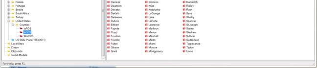
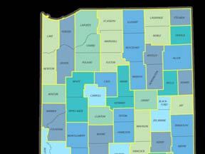
9 LOW DISTORTION PROJECTIONS A LOW DISTORTION PROJECTION MINIMIZES THE DIFFERENCE BETWEEN THE GRID AND GROUND DISTANCES BY CREATING A MINNIE STATE PLANE TYPE PROJECTION OVER A SMALLER AREA THAN WHAT IS TYPICALLY DONE. THIS ALLOWS THE USER OF THE LDP TO CONVERT WGS 84 COORDINATES (LAT/LONG) TO A PLANE COORDINATE SYSTEM (LDP) WITH LITTLE EFFORT. THE END USER SELECTS HIS/HER COUNTY PROJECTION AS SIMPLY AS SELECTING OHIO NORTH OR SOUTH ZONE. LOW DISTORTION PROJECTIONS THE NEW LOW DISTORTION PROJECTION SYSTEM WE ARE PROPOSING AT ODOT IS BASED ON COUNTY BOUNDARIES BY USING COUNTY BOUNDARIES (TYPICALLY MILES WIDE) WE MANIPULATE OUR CENTRAL MERIDIAN AND SCALE FACTOR TO TWEAK THE PLANE TO CLOSELY MATCH THE SIZE AND GENERAL TERRAIN OF THE COUNTY. DISTORTION BETWEEN GRID AND GROUND FOUND IN OUR TESTING IS ROUGHLY 1:300,000 IN OUR NORTHERN FLATLANDS AND 1:50,000 IN OUR SOUTHEASTERN HILLS 1:300,000 9


10 LOW DISTORTION PROJECTIONS PROJECTIONS ARE DESIGNED BASED ON THE SHAPE OF THE COUNTY. COUNTIES THAT LIE PREDOMINANTLY EAST AND WEST RECEIVE LAMBERT CONFORMAL CONIC PROJECTIONS MAHONING LOW DISTORTION PROJECTIONS COUNTIES THAT PREDOMINATELY LIE NORTH AND SOUTH RECEIVE TRANSVERSE MERCATOR PROJECTIONS. SUMMIT 10
11 LOW DISTORTION PROJECTIONS WORK FLOW FOR SURVEYORS USING A LOW DISTORTION PROJECTION IS AS SIMPLE AS SELECTING THE COUNTY YOU ARE WORKING IN. NO CALCULATING SCALE FACTORS PROJECTS WITHIN A COUNTY ALL FIT SEAMLESSLY TOGETHER GEODETIC TOOL KITS AND EQUIPMENT MANUFACTUER S SOFTWARE HANDLE THE PROJECTION. WE ARE NOT THE FIRST TO COME UP WITH THIS: Oregon has regional Low Distortion Projection Zones established that minimize distortion based on topography. Iowa also has regional Low Distortion Projection Zones Wisconsin and Indiana have Low Distortion Projections based on county boundaries similar to what we are proposing. 11


12 WISCONSIN: WISCRS INDIANA: INGCS 12
13 13

14 14

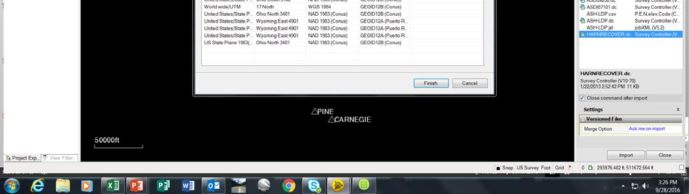
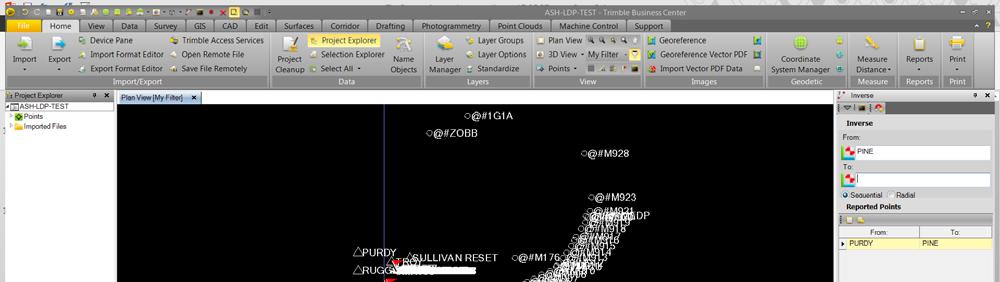
15 THE PROOF IS IN THE TESTING: OHIO NORTH STATE PLANE COORDINATES: STATION PURDY TO PINE GRID DISTANCE = GROUND DISTANCE = RESULT = FEET PER MILE 1 : 10,000 LOW DISTORTION PROJECTION COORDINATES: STATION PURDY TO PINE GRID DISTANCE = GROUND DISTANCE = RESULT = FEET PER MILE 1 : 333,000 15


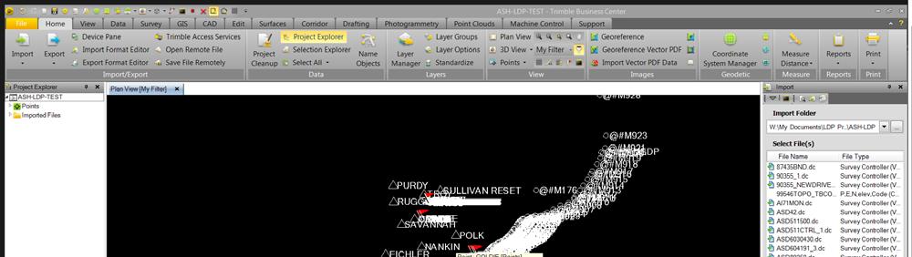
16 WHAT ABOUT MICROSTATION? FUTURE GOALS THE GOAL WILL BE TO HAVE SEED FILES SET UP WITH ALL OF THE LDP PROJECTIONS. WHEN YOU CREATE YOUR PROJECT IN THE ODOTcadd_CreateNewProject VBA THE CUSTOM GEOGRAPHIC COORDINATE SYSTEM FILE WILL BE AUTOMATICALLY SET IN THE DRAWING. QUESTIONS? COMMENTS? WHERE DO WE GO FROM HERE? 16
State Plane Coordinates and Computations using them GISC Spring 2013
 State Plane Coordinates and Computations using them GISC-3325 - Spring 2013 Map Projections From UNAVCO site hosting.soonet.ca/eliris/gpsgis/lec2geodesy.html Taken from Ghilani, SPC State Plane Coordinate
WHERE THEORY MEETS PRACTICE
 world from others, leica geosystems WHERE THEORY MEETS PRACTICE A NEW BULLETIN COLUMN BY CHARLES GHILANI ON PRACTICAL ASPECTS OF SURVEYING WITH A THEORETICAL SLANT february 2012 ² ACSM BULLETIN ² 27 USGS
ANGLES 4/18/2017. Surveying Knowledge FE REVIEW COURSE SPRING /19/2017
 FE REVIEW COURSE SPRING 2017 Surveying 4/19/2017 Surveying Knowledge 4 6 problems Angles, distances, & trigonometry Area computations Earthwork & volume computations Closure Coordinate systems State plane,
Convert Local Coordinate Systems to Standard Coordinate Systems
 BENTLEY SYSTEMS, INC. Convert Local Coordinate Systems to Standard Coordinate Systems Using 2D Conformal Transformation in MicroStation V8i and Bentley Map V8i Jim McCoy P.E. and Alain Robert 4/18/2012
3.1 Units. Angle Unit. Direction Reference
 Various settings allow the user to configure the software to function to his/her preference. It is important to review all the settings prior to using the software to ensure they are set to produce the
LECTURE TWO Representations, Projections and Coordinates
 LECTURE TWO Representations, Projections and Coordinates GEOGRAPHIC COORDINATE SYSTEMS Why project? What is the difference between a Geographic and Projected coordinate system? PROJECTED COORDINATE SYSTEMS
SurvCE: Localizations
 SurvCE: Localizations Mark Silver Electrical Engineer, not a Surveyor Carlson Dealer in Salt Lake City Utah Embarrassing Fact: I have a 250,000+ sheet paper map collection. igage Mapping Corporation www.igage.com
Geocoding and Georeferencing. Scott Bell GIS Institute
 Geocoding and Georeferencing Scott Bell GIS Institute Learning Outcomes Define coordinate system and map projection Relate coordinate systems and map projections Distinguish between defining and changing
Novel Real-Time Coordinate Transformations based on N-Dimensional Geo-Registration Parameters' Matrices
 FIG Working Week 009, Eilat, Israel, -8 May 009 Novel Real-Time Coordinate Transformations based on N-Dimensional Geo-Registration Parameters' Matrices Sagi Dalyot, Ariel Gershkovich, Yerach Doythser Mapping
Real Geodetic Map (Map without Projection) Abstract Keywords: 1. Introduction
 Abstract Keywords: 1. Introduction") Real ( without Projection) Ahmad Shaker 1 Abdullah Saad 1 Abdurrahman Arafa 2* 1.Surveying Dep., Shoubra Faculty of Engineering, Benha University, Egypt 2.Manager of Surveying Dep. in Horse Company. Egypt
Real ( without Projection) Ahmad Shaker 1 Abdullah Saad 1 Abdurrahman Arafa 2* 1.Surveying Dep., Shoubra Faculty of Engineering, Benha University, Egypt 2.Manager of Surveying Dep. in Horse Company. Egypt
Base Configurations Carlson SurvCE
 There are six methods to set the stationary base position, organized into 2 categories: From New Position includes Read from GPS, Enter Lat/Long and Enter Grid System Coordinates. The From Known Position
Geometric Correction of Imagery
 Geometric Correction of Imagery Geometric Correction of Imagery Present by: Dr.Weerakaset Suanpaga D.Eng(RS&GIS) The intent is to compensate for the distortions introduced by a variety of factors, so that
Alternative Solutions for RTK-GPS Applications in Building and Road Constructions
 Open Journal of Civil Engineering, 2015, 5, 312-321 Published Online September 2015 in SciRes. http://www.scirp.org/journal/ojce http://dx.doi.org/10.4236/ojce.2015.53031 Alternative Solutions for RTK-GPS
RIGTERSBLEEK - AALTEN 4 - B RB ENSCHEDE - THE NETHERLANDS
 RIGTERSBLEEK - AALTEN 4 - B17 7521 RB ENSCHEDE - THE NETHERLANDS Tel +31-53 4342001 - Fax +31 53 4302845 - Hot line +31 6 51363197 Email trackair@compuserve.com Internet http://www.trackair.com THE TRACKER
Smart GIS Course. Developed By. Mohamed Elsayed Elshayal. Elshayal Smart GIS Map Editor and Surface Analysis. First Arabian GIS Software
 Smart GIS Course Developed By Mohamed Elsayed Elshayal Elshayal Smart GIS Map Editor and Surface Analysis First Arabian GIS Software http://www.freesmartgis.blogspot.com/ http://tech.groups.yahoo.com/group/elshayalsmartgis/
UNIVERSITY CALIFORNIA, RIVERSIDE AERIAL TARGET GROUND CONTROL SURVEY REPORT JOB # DATE: MARCH 2011
 UNIVERSITY CALIFORNIA, RIVERSIDE AERIAL TARGET GROUND CONTROL SURVEY REPORT JOB # 2011018 DATE: MARCH 2011 UNIVERSITY CALIFORNIA, RIVERSIDE AERIAL TARGET GROUND CONTROL SURVEY REPORT I. INTRODUCTION II.
Purpose : Understanding Projections, 12D, and the System 1200.
 Purpose : Understanding Projections, 12D, and the System 1200. 1. For any Cad work created inside 12D, the distances entered are plane (Horizontal Chord) distances. 2. Setting a projection, or changing
3. Map Overlay and Digitizing
 3. Map Overlay and Digitizing 3.1 Opening Map Files NavviewW/SprayView supports digital map files in ShapeFile format from ArcView, DXF format from AutoCAD, MRK format from AG-NAV, Bitmap and JPEG formats
BASIC MATHEMATICS FOR CADASTRAL MAPPING
 BASIC MATHEMATICS FOR CADASTRAL MAPPING Chapter 5 2015 Cadastral Mapping Manual 5-1 Introduction Data which a mapper must use to solve problems comes from a myriad of sources both new and old. The general
SPECS FOR G.I.S. DATA PROVIDED TO ONE-CALL
 SPECS FOR G.I.S. DATA PROVIDED TO ONE-CALL DIGITAL MAPPING FILES (very efficient/extremely accurate): 1. G.I.S. dataset formats that we can accept: FORMAT FILE EXT(S) FORMAT FILE EXT(S) AutoCAD (*.dwg,
10.1 Conversions. Grid to Geodetic
 10.1 Conversions Geodetic conversions work with the current geodetic settings. Convert grid coordinates to geodetic (Latitude/Longitude) or vice versa with any of the available projections. All results
MLEP Intermediate GPS Workshop Exercise Two Using Maps
 During this exercise, you will scale coordinates from a map and enter them into the GPS receiver. This requires a ruler (provided) and all calculations require a paper and pencil. During this exercise,
COORDINATE TRANSFORMATION. Lecture 6
 COORDINATE TRANSFORMATION Lecture 6 SGU 1053 SURVEY COMPUTATION 1 Introduction Geomatic professional are mostly confronted in their work with transformations from one two/three-dimensional coordinate system
SPECS FOR G.I.S. DATA PROVIDED TO ONE-CALL
 SPECS FOR G.I.S. DATA PROVIDED TO ONE-CALL DIGITAL MAPPING FILES (very efficient/extremely accurate): 1. G.I.S. dataset formats that we can accept: FORMAT FILE EXT(S) FORMAT FILE EXT(S) AutoCAD (*.dwg,
HP-33S Calculator Program TM 1
 Programmer: Dr. Bill Hazelton Date: March, 2005. Line Instruction Line Instruction Line Instruction T0001 LBL T U0022 STOP U0061 x < > y T0002 CL Σ U0023 RCL U U0062 x < 0? T0003 INPUT K U0024 RCL E U0063
SPECS FOR G.I.S. DATA PROVIDED TO ONE-CALL
 SPECS FOR G.I.S. DATA PROVIDED TO ONE-CALL DIGITAL MAPPING FILES (very efficient/extremely accurate): 1. G.I.S. dataset formats that we can accept: FORMAT FILE EXT(S) FORMAT FILE EXT(S) AutoCAD (*.dwg,
Reduction of Field Observations
 Reduction of Field Observations GNSS/GPS measurements or Latitudes, Longitudes, HAE: We re interested in projected coordinates, e.g., State Plane Survey measurements in a projected coordinate system, on
GPS What is it? Combination of: Orbiting satellites
 Chart Your Course: Guidelines for GPS Mapping Dave Ragan Ragan Technical Solutions, Inc. www.ragantechnical.com GPS What is it? Combination of: Orbiting satellites GPS What is it? Orbiting satellites Combination
Lewis County Public Works Department (County) GIS Mapping Division 350 N. Market Blvd. Chehalis, WA Phone: Fax:
 GIS Mapping Division 350 N. Market Blvd. Chehalis, WA Phone: Fax:") March 31, 2005 Project Report Lewis County, WA Contract #2262-H Report Presented to: Lewis County Public Works Department (County) GIS Mapping Division 350 N. Market Blvd. Chehalis, WA 98532-2626 Phone:
March 31, 2005 Project Report Lewis County, WA Contract #2262-H Report Presented to: Lewis County Public Works Department (County) GIS Mapping Division 350 N. Market Blvd. Chehalis, WA 98532-2626 Phone:
Well Unknown ID AKA EPSG: 3857
 Well Unknown ID AKA EPSG: 3857 Pamela Kanu November 2016 WGS 1984 WEB MERCATOR ALIASES: AUXILIARY SPHERE, WKID: 3857, WKID: 102100, WKID: 102113, SHERICAL MERCATOR, WGS 84/PSEUDO-MERCATOR, OPEN LAYERS:
Georeferencing Maps With Contours
 Georeferencing Maps With Contours Peter BAJCSY National Center for Supercomputing Applications 605 East Springfield Avenue, Champaign, IL 61820 and Tyler J. ALUMBAUGH National Center for Supercomputing
Chapter 8 Options (updated September 06, 2009)
") Chapter 8 Options (updated September 06, 2009) Setting Up The Working Environment...................................................8-3 Options Library Manager.............................................................8-4
Chapter 8 Options (updated September 06, 2009) Setting Up The Working Environment...................................................8-3 Options Library Manager.............................................................8-4
SPECIFICATIONS FOR G.I.S. DATA/INFORMATION PROVIDED TO ONE-CALL
 SPECIFICATIONS FOR G.I.S. DATA/INFORMATION PROVIDED TO ONE-CALL Digital Mapping Files that we can accept: 1. G.I.S. dataset formats that we can accept: AutoCad File Latest Releases (*.DWG, *.DXF) ESRI
RECOMMENDATION ITU-R P DIGITAL TOPOGRAPHIC DATABASES FOR PROPAGATION STUDIES. (Question ITU-R 202/3)
") Rec. ITU-R P.1058-1 1 RECOMMENDATION ITU-R P.1058-1 DIGITAL TOPOGRAPHIC DATABASES FOR PROPAGATION STUDIES (Question ITU-R 202/3) Rec. ITU-R P.1058-1 (1994-1997) The ITU Radiocommunication Assembly, considering
Rec. ITU-R P.1058-1 1 RECOMMENDATION ITU-R P.1058-1 DIGITAL TOPOGRAPHIC DATABASES FOR PROPAGATION STUDIES (Question ITU-R 202/3) Rec. ITU-R P.1058-1 (1994-1997) The ITU Radiocommunication Assembly, considering
Technical Specifications
 1 Contents INTRODUCTION...3 ABOUT THIS LAB...3 IMPORTANCE OF THIS MODULE...3 EXPORTING AND IMPORTING DATA...4 VIEWING PROJECTION INFORMATION...5...6 Assigning Projection...6 Reprojecting Data...7 CLIPPING/SUBSETTING...7
Iowa Department of Transportation Office of Design. Photogrammetric Mapping Specifications
 Iowa Department of Transportation Office of Design Photogrammetric Mapping Specifications March 2015 1 Purpose of Manual These Specifications for Photogrammetric Mapping define the standards and general
SPECIFICATIONS FOR G.I.S. DATA/INFORMATION PROVIDED TO ONE-CALL
 SPECIFICATIONS FOR G.I.S. DATA/INFORMATION PROVIDED TO ONE-CALL Digital Mapping Files that we can accept: 1. G.I.S. dataset formats that we can accept: FORMAT AutoCad File Latest Releases ESRI Arc/Info
Bill Cusworth CREATING ORIENTEERING BASEMAPS USING LIDAR DATA
 Bill Cusworth CREATING ORIENTEERING BASEMAPS USING LIDAR DATA 1 BILL CUSWORTH Started Orienteering in 1992 in Seattle with Cascade Orienteering Club. Started making maps in 1993 and became more serious
GRASS GIS - Introduction
 GRASS GIS - Introduction What is a GIS A system for managing geographic data. Information about the shapes of objects. Information about attributes of those objects. Spatial variation of measurements across
TPC Desktop Series. Geodetic Learning Guide
 TPC Desktop Series Geodetic Learning Guide 1/18 NOTICE The information in this document is subject to change without notice. TRAVERSE PC. Inc. assumes no responsibility for any errors that may appear in
How to Create the Best Suitable Map Projection
 How to Create the Best Suitable Map Projection Yury HURYEU and Uladzimir PADSHYVALAU, Belarus Key words: map projection, best suitable projection, polyconic projection, composite projection, coordinate
BOWLING GREEN VERTICAL CONTROL NETWORK (BGVCN)
") BOWLING GREEN VERTICAL CONTROL NETWORK (BGVCN) THE CITY OF BOWLING GREEN June 2009 POGGEMEYER DESIGN GROUP Dana A. Parsell, P.S. Poggemeyer Design Group 1168 North Main Street Bowling Green, Ohio 43402
BOWLING GREEN VERTICAL CONTROL NETWORK (BGVCN) THE CITY OF BOWLING GREEN June 2009 POGGEMEYER DESIGN GROUP Dana A. Parsell, P.S. Poggemeyer Design Group 1168 North Main Street Bowling Green, Ohio 43402
Fundamentals of Surveying MSS 220 Prof. Gamal El-Fiky
 Fundamentals of Surveying MSS 220 Prof. Gamal l-fiky Maritime Studies Department, Faculty of Marine Science King Abdulaziz University gamal_elfiky@yahoo.com Room 221 What is Surveying? Surveying is defined
Project Report Nooksack South Fork Lummi Indian Nation. Report Presented to:
 June 5, 2005 Project Report Nooksack South Fork Lummi Indian Nation Contract #2291-H Report Presented to: Lummi Indian Nation Natural Resources Department 2616 Kwina Road Bellingham, WA 98226 Point of
Fundamentals of Structural Geology Exercise: concepts from chapter 2
 0B Reading: Fundamentals of Structural Geology, Ch 2 1) Develop a MATLAB script that plots the spherical datum (Fig. 2.1a) with unit radius as a wire-frame diagram using lines of constant latitude and
VLA Test Memorandum 102. Site Coordinate Systems and Conversions. C. M. Wade 20 February 1974
 VLA Test Memorandum 102 Site Coordinate Systems and Conversions C. M. Wade 20 February 1974 MAR 1 3 1974 Abstract The conversions between geodetic coordinates, the New Mexico State Plane Coordinate System,
Understanding and Using Geometry, Projections, and Spatial Reference Systems in ArcGIS. Rob Juergens, Melita Kennedy, Annette Locke
 Understanding and Using Geometry, Projections, and Spatial Reference Systems in ArcGIS Rob Juergens, Melita Kennedy, Annette Locke Introduction We want to give you a basic understanding of geometry and
GIS Mapping of Pipelines
 GIS Mapping of Pipelines RJ Lumbrezer, PS Survey Manager DGL Consulting Engineers, LLC Ted Muns Sales Manager City Blueprint of Toledo 2016 Ohio GIS Conference Hyatt Regency Columbus September 28 30, 2016
APPENDIX 13 TERRAIN NAVIGATOR PRO BASICS. Prepared by the Mapping and Marking Committee. Fifth Edition (Revised and Expanded) June 2014
 June 2014") APPENDIX 13 TERRAIN NAVIGATOR PRO BASICS Prepared by the Mapping and Marking Committee Fifth Edition (Revised and Expanded) June 2014 Published by the Oregon-California Trails Association P.O. Box 1019
APPENDIX 13 TERRAIN NAVIGATOR PRO BASICS Prepared by the Mapping and Marking Committee Fifth Edition (Revised and Expanded) June 2014 Published by the Oregon-California Trails Association P.O. Box 1019
Michigan Department of Transportation
 Michigan Department of Transportation Design Survey Manual Table of Contents Part I: Principles of Surveying 1.1 Surveying, Defined 1.2 Types of Survey 1.2.1 Plane 1.2.2 Geodetic 1.3 Datums 1.3.1 Horizontal
HP-35s Calculator Program Closure 7A
 Traverse Program using Latitude and Longitude and the Gauss Mid-Latitude Formulae Programmer: Dr. Bill Hazelton Date: March, 2008. Version: 1.0 Line Instruction Display User Programming Instructions J001
Geometric Rectification of Remote Sensing Images
 Geometric Rectification of Remote Sensing Images Airborne TerrestriaL Applications Sensor (ATLAS) Nine flight paths were recorded over the city of Providence. 1 True color ATLAS image (bands 4, 2, 1 in
Doc #: IDI06-11F Rev: 1.3 Issued: 22/02/18. Well Seeker PRO How To Guide Rev 1.3. Page 1 of 26
 Well Seeker PRO How To Guide Rev 1.3 Page 1 of 26 Contents 1.0 - Getting Started... 4 1.1 - Display... 4 2.0 - Creating a new Well... 5 2.1 - Unit Selection... 5 2.2 - New Instant Plan / Survey... 6 2.3
LOCAL GEODETIC HORIZON COORDINATES
 LOCAL GEODETIC HOIZON COODINATES In many surveying applications it is necessary to convert geocentric Cartesian coordinates X,,Z to local geodetic horizon Cartesian coordinates E,N,U (East,North,Up). Figure
DASHBOARD OPERATION MANUAL. Machine Control, Inc.
 DASHBOARD OPERATION MANUAL Machine Control, Inc. INTEGRATE YOUR DATA With highly accurate topographic data describing your job site, its easy to envision and design a multiphase system to address your
Geolocation with FW 6.4x & Video Security Client Geolocation with FW 6.4x & Video Security Client 2.1 Technical Note
 Geolocation with FW 6.4x & Video Security Client 2.1 1 10 Geolocation with FW 6.4x & Video Security Client 2.1 Technical Note Geolocation with FW 6.4x & Video Security Client 2.1 2 10 Table of contents
Chapter 2 File Management (updated September 5, 2009)
") Chapter 2 File Management (updated September 5, 2009) General Discussion.................................................................2-3 Creating New Project................................................................2-5
Chapter 2 File Management (updated September 5, 2009) General Discussion.................................................................2-3 Creating New Project................................................................2-5
Navigation coordinate systems
 Lecture 3 Navigation coordinate systems Topic items: 1. Basic Coordinate Systems. 2. Plane Cartesian Coordinate Systems. 3. Polar Coordinate Systems. 4. Earth-Based Locational Reference Systems. 5. Reference
Box Calibration: Here I entered points 3 and 4 which are the only control points given to us in the plans.
 Box Calibration: Trimble machine control does not like files that are derived from State Plane Coordinates or files that contain a Geoid. Trimble representatives want everyone to do a site calibration
Updating Autonomous Start to an RTK Field Survey (Part II)
") Updating Autonomous Start to an RTK Field Survey (Part II) Oscar R. Cantu Topcon University FTP Site For access to previously offered webinars and supporting documentation, please go to: ftp://tulive+topconuniversity.com:tulive@ftp.topconuniversity.com
Updating Autonomous Start to an RTK Field Survey (Part II) Oscar R. Cantu Topcon University FTP Site For access to previously offered webinars and supporting documentation, please go to: ftp://tulive+topconuniversity.com:tulive@ftp.topconuniversity.com
High-Precision Positioning Unit 2.2 Student Exercise: Calculating Topographic Change
 High-Precision Positioning Unit 2.2 Student Exercise: Calculating Topographic Change Ian Lauer and Ben Crosby (Idaho State University) Change is an inevitable part of our natural world and varies as a
CONFIRMATION OF VERTICAL SURVEY CONTROL IN THE BIRDS POINT-NEW MADRID FLOODWAY Final Report 10/27/2015
 Reply to Attention of: DEPARTMENT OF THE ARMY MEMPHIS DISTRICT CORPS OF ENGINEERS 167 NORTH MAINSTREET B-202 MEMPHIS, TENNESSEE 38103-1894 CONFIRMATION OF VERTICAL SURVEY CONTROL IN THE BIRDS POINT-NEW
Investigation of the Use of the Ellipsoidal Normal to Model the Plumb Line in a Millimeter Cadastre
 Investigation of the Use of the Ellipsoidal Normal to Model the Plumb Line in a Millimeter Cadastre Carlton A. BROWN, USA Key words: Cadastre, Land Tenure. ABSTRACT It may soon become possible to routinely
Geometric Correction
 CEE 6150: Digital Image Processing Geometric Correction 1 Sources of Distortion Sensor Characteristics optical distortion aspect ratio non-linear mirror velocity detector geometry & scanning sequence Viewing
Use of n-vector for Radar Applications
 Use of n-vector for Radar Applications Nina Ødegaard, Kenneth Gade Norwegian Defence Research Establishment Kjeller, NORWAY email: Nina.Odegaard@ffi.no Kenneth.Gade@ffi.no Abstract: This paper aims to
President of X DOT, Inc. NSMA 2014 Conference
 Coordinate Inaccuracies Presented by James C. Wolfson President of X DOT, Inc. NSMA 2014 Conference Introduction Review FCC/FAA coordinate and elevation requirements FAA Accuracy Codes Examples Tower site,
Project Report Snohomish County Floodplains LiDAR Survey. Report Presented to:
 August 22, 2005 Project Report Snohomish County Floodplains LiDAR Survey Contract #2295-H Report Presented to: David Evans and Associates, Inc. (DEA) 1620 W. Marine View Drive, Suite 200 Everett, WA 98201
Project Report Sauk-Suiattle Indian Tribe. Report Presented to:
 July 28, 2005 Project Report Sauk-Suiattle Indian Tribe Contract #2294-H Report Presented to: Sauk-Suiattle Indian Tribe 5318 Chief Brown Lane Darrington, WA 98241 Phone: (360) 436-0738 Fax: (360) 436-1092
PDHonline Course L154G (5 PDH) Data in GIS. Instructor: Steve Ramroop, Ph.D. PDH Online PDH Center
 Data in GIS. Instructor: Steve Ramroop, Ph.D. PDH Online PDH Center") PDHonline Course L154G (5 PDH) Data in GIS Instructor: Steve Ramroop, Ph.D. 2012 PDH Online PDH Center 5272 Meadow Estates Drive Fairfax, VA 22030-6658 Phone & Fax: 703-988-0088 www.pdhonline.org www.pdhcenter.com
PDHonline Course L154G (5 PDH) Data in GIS Instructor: Steve Ramroop, Ph.D. 2012 PDH Online PDH Center 5272 Meadow Estates Drive Fairfax, VA 22030-6658 Phone & Fax: 703-988-0088 www.pdhonline.org www.pdhcenter.com
Chapter 3. Survey Module 312
 Selecting Print (editor File menu) provided this Level File Report sample Editor Columns: Type: These are small pulldown menus with two-letter level procedure choices. The two letters are abbreviations
Section 1.2: Points and Lines
 Section 1.2: Points and Lines Objective: Graph points and lines using x and y coordinates. Often, to get an idea of the behavior of an equation we will make a picture that represents the solutions to the
The National Geodetic Survey NADCON Tool
 The National Geodetic Survey NADCON Tool The most frequently used item in the NGS Geodetic Tool Kit is the North American Datum Conversion (NADCON) tool. NADCON transforms geographic coordinates between
Accuracy Assessment of an ebee UAS Survey
 Accuracy Assessment of an ebee UAS Survey McCain McMurray, Remote Sensing Specialist mmcmurray@newfields.com July 2014 Accuracy Assessment of an ebee UAS Survey McCain McMurray Abstract The ebee unmanned
Question: What are the origins of the forces of magnetism (how are they produced/ generated)?
?") This is an additional material to the one in the internet and may help you to develop interest with the method. You should try to integrate some of the discussions here while you are trying to answer the
This is an additional material to the one in the internet and may help you to develop interest with the method. You should try to integrate some of the discussions here while you are trying to answer the
Section G. POSITIONAL ACCURACY DEFINITIONS AND PROCEDURES Approved 3/12/02
 Section G POSITIONAL ACCURACY DEFINITIONS AND PROCEDURES Approved 3/12/02 1. INTRODUCTION Modern surveying standards use the concept of positional accuracy instead of error of closure. Although the concepts
Applying Geodetic Coordinate Reference Systems in Building Information Modeling (BIM)
") Applying Geodetic Coordinate Reference Systems in Building Information Modeling (BIM) Presented at the FIG Working Week 2017, May 29 - June 2, 2017 in Helsinki, Finland Robert Kaden und Christian Clemen
Applying Geodetic Coordinate Reference Systems in Building Information Modeling (BIM) Presented at the FIG Working Week 2017, May 29 - June 2, 2017 in Helsinki, Finland Robert Kaden und Christian Clemen
Features and Benefits
 CAiCE Visual Survey 10 Features and Benefits CAiCE Visual Survey 10 software enables surveying professionals to import, process, analyze, and present surveying all in one software package. Visual Survey
ROCKY FORK TRACT: VIEWSHED ANALYSIS REPORT
 ROCKY FORK TRACT: VIEWSHED ANALYSIS REPORT Prepared for: The Conservation Fund Prepared by: A Carroll GIS 3711 Skylark Trail Chattanoga, TN 37416 INTRODUCTION This report documents methods and results
Geology and Calculus
 GEOL 452 - Mathematical Tools in Geology Lab Assignment # 6 - Feb 25, 2010 (Due March 9, 2010) Name: Geology and Calculus A. Volume of San Nicolas Island San Nicolas Island is one of the remote and smaller
Wednesday, July 15, Author: Eldris Ferrer Gonzalez, M.Sc. Engineering CSA Group
 Twenty ninth Annual ESRI International User Conference Wednesday, July 15, 2009 Author: Eldris Ferrer Gonzalez, M.Sc. Engineering CSA Group Introduction to Valenciano Project LIDAR Survey for Valenciano
SURPAC Surveying Software Version 5.65 for Windows XP/Vista/7/8/10
 SURPAC Surveying Software Version 5.65 for Windows XP/Vista/7/8/10 Topographical, Engineering, Mining and Cadastral Surveying Applications Topographical, Engineering, Mining and Cadastral Surveying Applications
Google Earth an introduction
 Luana Valentini InternetGIS course - 2011 Google Earth an introduction Google Earth combines the power of Google Search with satellite imagery, maps, terrain and 3D buildings to put the world's geographic
CHAPTER 01 Basics of Surveying
 CHAPTER 01 Basics of Surveying 1.1 How do plane surveys and geodetic surveys differ? Plane surveying assumes all horizontal measurements are taken on a single plane and all vertical measurements are relative
On Grid: Tools and Techniques to Place Reality Data in a Geographic Coordinate System
 RC21940 On Grid: Tools and Techniques to Place Reality Data in a Geographic Coordinate System Seth Koterba Principal Engineer ReCap Autodesk Ramesh Sridharan Principal Research Engineer Infraworks Autodesk
GPS/GIS Activities Summary
 GPS/GIS Activities Summary Group activities Outdoor activities Use of GPS receivers Use of computers Calculations Relevant to robotics Relevant to agriculture 1. Information technologies in agriculture
RAPIDMAP Geocortex HTML5 Viewer Manual
 RAPIDMAP Geocortex HTML5 Viewer Manual This site was developed using the evolving HTML5 web standard and should work in most modern browsers including IE, Safari, Chrome and Firefox. Even though it was
1. Introduction Surveying Method chosen depends on:
 1. Introduction Surveying Method chosen depends on: by the purpose of the survey e.g. map making, location of specific points, definition of land ownership etc., by the nature of the survey itself e.g.
BRIEF EXAMPLES OF PRACTICAL USES OF LIDAR
 BRIEF EXAMPLES OF PRACTICAL USES OF LIDAR PURDUE ROAD SCHOOL - 3/9/2016 CHRIS MORSE USDA-NRCS, STATE GIS COORDINATOR LIDAR/DEM SOURCE DATES LiDAR and its derivatives (DEMs) have a collection date for data
How to Relay Information About Where You Are
 How to Relay Information About Where You Are 2017 12 18 Gary Ataman Five Winds Backcountry Ski Club President Where Are You? When you are in the backcountry keep track of where you are. When incidents
GEON LiDAR Workflow (GLW) Users Guide
 Users Guide") GEON LiDAR Workflow (GLW) Users Guide Joshua Coyan Christopher Crosby Ramón Arrowsmith School of Earth and Space Exploration Arizona State University 24 October 2007 http://lidar.asu.edu Table of Contents
GEON LiDAR Workflow (GLW) Users Guide Joshua Coyan Christopher Crosby Ramón Arrowsmith School of Earth and Space Exploration Arizona State University 24 October 2007 http://lidar.asu.edu Table of Contents
Geographic Information Systems. using QGIS
 Geographic Information Systems using QGIS 1 - INTRODUCTION Generalities A GIS (Geographic Information System) consists of: -Computer hardware -Computer software - Digital Data Generalities GIS softwares
SSC-JE CIVIL ENGINEERING STUDY MATERIAL SURVEYING ENGINEERING STAFF SELECTION COMMISSION SURVEYING. Page 1 of 98 SSC-JE CIVIL ENGINEERING
 Page 1 of 98 SSC-JE STAFF SELECTION COMMISSION CIVIL ENGINEERING STUDY MATERIAL ENGINEERING Page 2 of 98 SSC-JE Civil Engineering : Surveying syllabus Surveying: Principles of surveying, measurement of
High Resolution Digital Elevation Model (HRDEM) CanElevation Series Product Specifications. Edition
 CanElevation Series Product Specifications. Edition") High Resolution Digital Elevation Model (HRDEM) CanElevation Series Product Specifications Edition 1.1 2017-08-17 Government of Canada Natural Resources Canada Telephone: +01-819-564-4857 / 1-800-661-2638
High Resolution Digital Elevation Model (HRDEM) CanElevation Series Product Specifications Edition 1.1 2017-08-17 Government of Canada Natural Resources Canada Telephone: +01-819-564-4857 / 1-800-661-2638
Point Cloud Classification
 Point Cloud Classification Introduction VRMesh provides a powerful point cloud classification and feature extraction solution. It automatically classifies vegetation, building roofs, and ground points.
Displaying Strike and Dip Measurements on Your Map in Surfer
 Displaying Strike and Dip Measurements on Your Map in Surfer Measuring strike and dip is a fundamental part of geological mapping, and displaying strike and dip information on a map is an effective way
+ Make it from the satellite images in sale, (Easier & Faster, but not always available) (It does cost much. An astronomical number!
 (It does cost much. An astronomical number!") BaseMap: + Look for it among the existent digital maps, (Easiest & Fastest because no processing required) (Therefore, the most desirable, but not always available) (It can cost much) + Make it from the
BaseMap: + Look for it among the existent digital maps, (Easiest & Fastest because no processing required) (Therefore, the most desirable, but not always available) (It can cost much) + Make it from the
Table of Contents 1 PURPOSE SCOPE DEFINITIONS PROCEDURE... 5
 Table of Contents 1 PURPOSE... 3 2 SCOPE... 3 3 DEFINITIONS... 4 4 PROCEDURE... 5 4.1 Overview - Performing a Site Calibration... 5 4.1.1 Upload Mine Grid Control... 6 4.1.2 Obtain SSM Data... 7 4.1.3
Central Coast LIDAR Project, 2011 Delivery 1 QC Analysis LIDAR QC Report February 17 th, 2012
 O R E G O N D E P A R T M E N T O F G E O L O G Y A N D M I N E R A L I N D U S T R I E S OLC Central Coast Delivery 1 Acceptance Report. Department of Geology & Mineral Industries 800 NE Oregon St, Suite
Measurement of Direction: Bearing vs. Azimuth
 Week 5 Monday Measurement of Direction: Bearing vs. Azimuth Bearing Is an angle of 90 o or less Measured from either North or South in easterly & westerly directions. North 22 o West, South 89 o West,
Basic Tasks in ArcGIS 10.3.x
 Basic Tasks in ArcGIS 10.3.x This guide provides instructions for performing a few basic tasks in ArcGIS 10.3.1, such as adding data to a map document, viewing and changing coordinate system information,