A short history of the PRG The first parachute inflation studies by Potvin began in 1994
|
|
|
- Brianne Martin
- 5 years ago
- Views:
Transcription
1 Development of a New Parachute Inflation Modeling Computer Program PIMS - Parachute Inflation Modeling Suite Gary Peek & Jean Potvin Parks College Parachute Research Group Parks College of Engineering, Aviation and Technology Saint Louis University, St. Louis MO Contact: peek@industrologic.com potvinj@slu.edu


2 A short history of the PRG The first parachute inflation studies by Potvin began in 1994


3 A short history of the PRG, cont d Peek has been studying the fall rate of skydivers since 1990, with a Barograph he designed
4 A short history of the PRG, cont d Peek and Potvin had infrequent contact until 1996 when they finally discussed their individual research efforts. "We should be working together!", they realized. In 1996 Peek and Potvin formed the PCPRG, created and began publishing some of their research. Their areas of expertise complemented each other.


5 A short history of the PRG, cont d Peek and Potvin combined their expertise in their first project: the measurement of riser force on a skydiving rig


")

6 A short history of the PRG, cont d Second team project Computer simulation of the drag force on sport ram-air air parachutes & comparison with test jump data (slider-descent descent stage) (Test drops carried out with funding from Performance Designs)
7 How to do a computer simulation of inflation? Simple model example: S(t)C (t)= 6 = = ½SC 2 D At +B Drag F D V (inflation part) Post-inflation deceleration model dl Steady descent Jagged line = experimental data

8 Why create PIMS? Pims arose from the lessons learned from these early efforts - Initial inflation simulation software of Potvin was ackward to use: written in FORTRAN; command line input; the code was linear; output t was only ASCII; graphing not a result of the computer run itself - The comparison of the computer simulations with test jump data was a very labor-intensive process; this can be a handicap given that for a given parachute design and set of drop/jump conditions, the inflation force evolution will change on a drop-to-drop basis. A large number of computer simulations were therefore needed more labor! - Peek and Potvin decided to write a totally new software inflation package - This effort involved the support of the US Army
9 What is PIMS? PIMS: Parachute Inflation Modeling Suite Development has been funded since 2001 by the US Army: Natick Soldier Center & Yuma Proving Ground R&D effort involves: software development validation - collection of inflation data from test drops Commercial version may be available ~

10 What does PIMS provide? Easy input via GUI Immediate graphing during the simulations Output also yields an ASCII simulation data files for detailed graphing using Excel or other spreadsheet programs
11 PIMS was written in Power Basic Why Power Basic? Peek had already used it for Industrologic application software and found it very good Other programming languages were expensive even for "academic" versions - Neither Peek nor Potvin had any experience with Visual Fortran
12 Characteristics of Power Basic Requires knowledge and use of Windows Application Programming Interface (API) Generates a single executable file (.EXE) No DLL files necessary No installation program necessary Executable is very small - PIMS.EXE is only 350K bytes! (including embedded graphics) Executable is very fast t( (calculations l and graphing almost ti instantaneous) t And last but not least- Source code syntax of Basic and Fortran are very close! - Combining Potvin's simulation code in Fortran with Peek's GUI in PowerBasic took only about 2 hours for the first version - Syntax was similar enough that Potvin abandoned the Fortran and started making changes to the Basic code in later versions

13 What does PIMS calculate? Basic output drag force speed drag area ballistic trajectory angle deceleration modulus Input inflation models parachute design characteristics drops conditions (altitude, acft speed, payload weight,etc)
14 Current and future parachutes type modeled by PIMS Parachute types (current version V3.0) Flat circular types (USAF C-9, USA T-10, etc.) Skirt-reefed reefed flat circular types Drive-slotted hemispherical types (USA MC1-1C, 1C, Crossbow, Pioneer K22, Phantom, etc.) Ring-slotted hemispherical types Unreefed ram-air air parafoil types (no slider) Parachute types and computational models (future versions) Ram-air air parafoils reefed with sliders (next version V3.1!) Round types with sliders Skirt reefed ring-slotted hemispherical types Supersonic inflation Fabric and line elasticity during inflation
15 Other important features Not a based on Computational Fluid Dynamics (CFD); rather uses the Newtonian equation of motions of the parachute-payload payload system and those of sub-components (canopy skirt, slider, etc.) Pims includes eight different inflations models Choice of gravitational constant (wanna jump on Mars or on Titan?) Tracks payload trajectory prior to parachute deployment Includes the simulation of the snatch force Includes a special model for the deceleration of the system after inflation (but prior to steady descent)
16 Pims does have some restrictions.. Input, output, and calculations in American Standard Units only Pims simulates parachute events that only involve subsonic airflows about the parachute Except for the snatch force simulation, Pims does not model the elastic properties of the canopy fabric and suspension lines (feature to be included in a future version) The inflation models do not include the occasional (and hard to predict) shedding of vortices from the canopy However Pims yields the correct - overall shape of a riser-load vs. time curve - temporal width of the curve (i.e. inflation duration) - maximum value of the force sustained
 inflation model Two-phase model V3.0 upgrade Round, wing or cruciform (high mass ratio) inflation model Two-phase model V3.")
17 pre-inflation processor - cubical container input? pre-inflation processor bypass; user inputs angle & speed Windows GUI *.mdl text file pre-inflation processor - palletized container? snatch force sim Snatch bypass? Round, wing or cruciform (low mass ratio) inflation model Two-phase model V3.0 upgrade Round, wing or cruciform (high mass ratio) inflation model Two-phase model V3.0 upgrade General (Pflanz) inflation model Lingard s inflation models: C-9 canopy or GQ Aeroconical 1000 canopy Drive-slotted rounds Low and high-mass ratio V3.0 upgrade PIMS V2.0, V2.1, V3.0 PIMS V1.0? User option post-inflation deceleration model output Windows: graphs and simulation data menu *.txt text file
18 Running Pims yields a graph and a menu


19 Sample menu functions: choosing the models


20 Sample menu functions: Parachute input parameters e

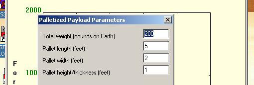

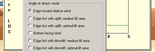


21 Sample menu functions: Other input parameters


22 Sample menu functions: Windows graphic output


23 Sample menu functions: Input file definition and use The mdl file stores all input and Pims settings of a particular run


24 Time,Speed 0.01, , , Sample menu functions: Output file definition and use , , , , , , , , , , , , , , , , , , , Th ttfil t l t dt j t tf hi The txt file stores selected trajectory ouput for graphing with spreadsheet program (Excel for example)
 = 2 Iteration interval (seconds) =.01 Air density (slugs/feet cubed) =.")
 = 90 Payload surface area of one CUBE face (feet squared) = 4 Angle of attack mode= CUBE Wedge first with uplift, optimal lift area Payload surface area")
25 Parachute type = round, for low mass ratio Sample menu functions: Diagnostic output file Deployment phase (pre-processor) Duration of deployment (seconds) = 1.5 Total simulation time (seconds) = 2 Iteration interval (seconds) =.01 Air density (slugs/feet cubed) =.0023 Aircraft speed (TAS in feet/second) = 160 Payload weight (pounds on Earth)= 110 Mass (slugs) = Acceleration of gravity (feet/seconds squared) = Trajectory angle (degrees, 90=horizontal) = 90 Payload surface area of one CUBE face (feet squared) = 4 Angle of attack mode= CUBE Wedge first with uplift, optimal lift area Payload surface area adjusted for angle of attack = 4 Initial payload py box drag coefficient upon leaving aircraft= 7.5 Steady state payload box drag coefficient (constant) = 1.12 Deployment duration (seconds) = 1.5 Payload size equivalent disk drag diameter (feet) = Terminal velocity of payload without parachute (feet/second) = The load decelerates TPhase1 (seconds) = 0 Pre-processor beta (only when motion flag=1) = Ratio of speed after Tphase1/Aircraft speed (correct only when load accelerates) = Snatch simulation Number of suspension lines = 28 Suspension line length (ft) = 14 Approx. payload drag area (sqf) = 4 Approx. chute initial drag area (sqf) = 16 Parachute weight (lb) = 5 Payload weight (lb) = 105 Spring force exponent = 3 Lines' breaking strength (lb) = 400 Percentage line elongation at breaking point = 20 Initial load-chute speed difference (fps) = 5 Snatch dynamics time scale (sec) = E-2 Payload drag dynamic time scale (sec) = Duration of snatch simulation (sec) = E-2 Maximum line tension generated = Inflation phase Steady state drag coefficient of parachute = 1.44 Round parachute constructed diameter (feet) = 14 Parachute flat surface area (square feet) = Ratio of projected mouth length-scale to (inflated) projected diameter =.2 Initial instant velocity (at line stretch or after snatch) (feet/second) = Parachute/payload descent terminal velocity (feet/second) = Initial trajectory angle (in degrees, 90=horizontal) = Steady state drag area of open parachute (feet/second) = Filling time (seconds) = Extra inflation simulation was carried out (peak force was not reached by filling time) Time peak drag (seconds) = Peak drag (pounds) = mass ratio = Cd-adjusted mass ratio = Froude number (using g =32.17) = Ballistic parameter = Ck-Factor (from raw sim data) = Post-inflation phase Post-inflation motion = deceleration Post-inflation beta =
26 Examples of Pims runs and comparison with test drop data
27 Introductory remarks The user must be knowledgable about inflation in general; in particular he/she must be aware that inflation duration depend on many factors of equal importance, such as: Parachute designs characteristics Payload characteristics Deployment method used The user must be aware of the variability of inflation characteristics on a drop-to-drop or jump-to-jump basis. It is necessary to perform repeat test drops and repeat PIMS runs in order to completely understand the inflation properties p of a given parachute design The user must know the limits of the various models being used in PIMS


28 Example: Round parachute type US. Army T-10C Red-dotted original model for round chutes Blue line upgraded model: Phase 1 cigar/light bulb expansion Phase 2 skirt/hem spreading

29 Example: Round parachute type - Half-scale USAF C-9 Thick red line = Pims V3.0 Thin blue and purple lines = Pims V2.1 In both versions 2 & 3, the end of the snatch phase needs improvement Versions 2 and 3 can t reproduce this shoulder
30 Example: Round parachute type US Army MC1-1C1C Red line unslotted round chute model Green line drive-dlotted round chute model
31 Example: Round parachute type US Army MC1-1C1C
32 Example: Round parachute type with drive slots - Security Crossbow
33 Example: Ram-air air type without slider symmetrical opening ( the cells of the right side of the span open at the time as the cells on the other side) The match is pretty good
34 Example: Ram-air air type without slider asymetrical opening ( the cells of one side of the span open before the cells on the other side) The match is not so good


35 To be included in V3.1: Ram-air air type with slider The smooth curve on the graph represents the slider-descent descent phase A model of the early pressurization phase -i.e. prior to slider-descent- is now being tested
36 Pims run demonstration
37 Questions?
Parachute Load Prediction using a Combination of Empirical Data and Fluid Structure Interaction Simulations
 21st AIAA Aerodynamic Decelerator Systems Technology Conference and Seminar 23-26 May 2011, Dublin, Ireland AIAA 2011-2544 Parachute Load Prediction using a Combination of Empirical Data and Fluid Structure
Study Guide and Review - Chapter 10
 State whether each sentence is true or false. If false, replace the underlined word, phrase, expression, or number to make a true sentence. 1. A triangle with sides having measures of 3, 4, and 6 is a
Study Guide and Review - Chapter 10
 State whether each sentence is true or false. If false, replace the underlined word, phrase, expression, or number to make a true sentence. 1. A triangle with sides having measures of 3, 4, and 6 is a
PROJECTILE MOTION PURPOSE
 PURPOSE The purpose of this experiment is to study the motion of an object in two dimensions. The motion of the projectile is analyzed using Newton's laws of motion. During the motion of the projectile,
Computational Fluid Dynamics Analysis of an Idealized Modern Wingsuit
 Washington University in St. Louis Washington University Open Scholarship Mechanical Engineering and Materials Science Independent Study Mechanical Engineering & Materials Science 12-21-2016 Computational
Development Of Computational Tools For Analysis And Evaluation Of Autonomous Parafoil Systems
 Development Of Computational Tools For Analysis And Evaluation Of Autonomous Parafoil Systems Esteban Gonzalez Garcia, Carlos G. Sacco, Aula CIMNE IUA Enrique Ortega, Roberto Flores, CIMNE Barcelona 2do
5/27/12. Objectives 7.1. Area of a Region Between Two Curves. Find the area of a region between two curves using integration.
 Objectives 7.1 Find the area of a region between two curves using integration. Find the area of a region between intersecting curves using integration. Describe integration as an accumulation process.
Egyptian Space Science and Technology Educational Project Based on Can-Sat Program (CLTP)
") Egyptian Space Science and Technology Educational Project Based on Can-Sat Program (CLTP) Samy Amin, Hassan Ali, Omar Magdy, Mohammad Khalil Aerospace Engineering Department, Cairo University. EGYPT [CanSat
Egyptian Space Science and Technology Educational Project Based on Can-Sat Program (CLTP) Samy Amin, Hassan Ali, Omar Magdy, Mohammad Khalil Aerospace Engineering Department, Cairo University. EGYPT [CanSat
NUMERICAL 3D TRANSONIC FLOW SIMULATION OVER A WING
 Review of the Air Force Academy No.3 (35)/2017 NUMERICAL 3D TRANSONIC FLOW SIMULATION OVER A WING Cvetelina VELKOVA Department of Technical Mechanics, Naval Academy Nikola Vaptsarov,Varna, Bulgaria (cvetelina.velkova1985@gmail.com)
Since a projectile moves in 2-dimensions, it therefore has 2 components just like a resultant vector: Horizontal Vertical
 Since a projectile moves in 2-dimensions, it therefore has 2 components just like a resultant vector: Horizontal Vertical With no gravity the projectile would follow the straight-line path (dashed line).
KCS Motion. Video Motion Analysis Software
 Video Motion Analysis Software Software and supporting material is property of G. Mason, Seattle University, 2007 Overview Overview KCS Motion tracks moving objects in a video clip and analyzes their position,
How to Enter and Analyze a Wing
 How to Enter and Analyze a Wing Entering the Wing The Stallion 3-D built-in geometry creation tool can be used to model wings and bodies of revolution. In this example, a simple rectangular wing is modeled
Aerodynamic Study of a Realistic Car W. TOUGERON
 Aerodynamic Study of a Realistic Car W. TOUGERON Tougeron CFD Engineer 2016 Abstract This document presents an aerodynamic CFD study of a realistic car geometry. The aim is to demonstrate the efficiency
Results from the Phoenix Atmospheric Structure Experiment
 Results from the Phoenix Atmospheric Structure Experiment Paul Withers 1 and David Catling 2 (1) Center for Space Physics, Boston University, USA (withers@bu.edu) (2) University of Washington, USA International
THE EFFECTS OF THE PLANFORM SHAPE ON DRAG POLAR CURVES OF WINGS: FLUID-STRUCTURE INTERACTION ANALYSES RESULTS
 March 18-20, 2013 THE EFFECTS OF THE PLANFORM SHAPE ON DRAG POLAR CURVES OF WINGS: FLUID-STRUCTURE INTERACTION ANALYSES RESULTS Authors: M.R. Chiarelli, M. Ciabattari, M. Cagnoni, G. Lombardi Speaker:
CFD modelling of thickened tailings Final project report
 26.11.2018 RESEM Remote sensing supporting surveillance and operation of mines CFD modelling of thickened tailings Final project report Lic.Sc.(Tech.) Reeta Tolonen and Docent Esa Muurinen University of
Unit 2: Functions and Graphs
 AMHS Precalculus - Unit 16 Unit : Functions and Graphs Functions A function is a rule that assigns each element in the domain to exactly one element in the range. The domain is the set of all possible
DYNAMICS OF A VORTEX RING AROUND A MAIN ROTOR HELICOPTER
 DYNAMICS OF A VORTEX RING AROUND A MAIN ROTOR HELICOPTER Katarzyna Surmacz Instytut Lotnictwa Keywords: VORTEX RING STATE, HELICOPTER DESCENT, NUMERICAL ANALYSIS, FLOW VISUALIZATION Abstract The main goal
GRID PATTERN EFFECTS ON AERODYNAMIC CHARACTERISTICS OF GRID FINS
 24 TH INTERNATIONAL CONGRESS OF THE AERONAUTICAL SCIENCES GRID PATTERN EFFECTS ON AERODYNAMIC CHARACTERISTICS OF GRID FINS Fumiya Hiroshima, Kaoru Tatsumi* *Mitsubishi Electric Corporation, Kamakura Works,
Experimental study of UTM-LST generic half model transport aircraft
 IOP Conference Series: Materials Science and Engineering PAPER OPEN ACCESS Experimental study of UTM-LST generic half model transport aircraft To cite this article: M I Ujang et al 2016 IOP Conf. Ser.:
Debojyoti Ghosh. Adviser: Dr. James Baeder Alfred Gessow Rotorcraft Center Department of Aerospace Engineering
 Debojyoti Ghosh Adviser: Dr. James Baeder Alfred Gessow Rotorcraft Center Department of Aerospace Engineering To study the Dynamic Stalling of rotor blade cross-sections Unsteady Aerodynamics: Time varying
Introduction to ANSYS CFX
 Workshop 03 Fluid flow around the NACA0012 Airfoil 16.0 Release Introduction to ANSYS CFX 2015 ANSYS, Inc. March 13, 2015 1 Release 16.0 Workshop Description: The flow simulated is an external aerodynamics
CFD Study of a Darreous Vertical Axis Wind Turbine
 CFD Study of a Darreous Vertical Axis Wind Turbine Md Nahid Pervez a and Wael Mokhtar b a Graduate Assistant b PhD. Assistant Professor Grand Valley State University, Grand Rapids, MI 49504 E-mail:, mokhtarw@gvsu.edu
Contents 10. Graphs of Trigonometric Functions
 Contents 10. Graphs of Trigonometric Functions 2 10.2 Sine and Cosine Curves: Horizontal and Vertical Displacement...... 2 Example 10.15............................... 2 10.3 Composite Sine and Cosine
Validation of Computational Structural Dynamics Models for Parachute Systems
 20th AIAA Aerodynamic Decelerator Systems Technology Conference and Seminar 4-7 May 2009, Seattle, Washington AIAA 2009-2934 Validation of Computational Structural Dynamics Models for Parachute Systems
WETTING PROPERTIES OF STRUCTURED INTERFACES COMPOSED OF SURFACE-ATTACHED SPHERICAL NANOPARTICLES
 November 20, 2018 WETTING PROPERTIES OF STRUCTURED INTERFACES COMPOSED OF SURFACE-ATTACHED SPHERICAL NANOPARTICLES Bishal Bhattarai and Nikolai V. Priezjev Department of Mechanical and Materials Engineering
DAMAGE INSPECTION AND EVALUATION IN THE WHOLE VIEW FIELD USING LASER
 DAMAGE INSPECTION AND EVALUATION IN THE WHOLE VIEW FIELD USING LASER A. Kato and T. A. Moe Department of Mechanical Engineering Chubu University Kasugai, Aichi 487-8501, Japan ABSTRACT In this study, we
Projectile Trajectory Scenarios
 Projectile Trajectory Scenarios Student Worksheet Name Class Note: Sections of this document are numbered to correspond to the pages in the TI-Nspire.tns document ProjectileTrajectory.tns. 1.1 Trajectories
Coupling of STAR-CCM+ to Other Theoretical or Numerical Solutions. Milovan Perić
 Coupling of STAR-CCM+ to Other Theoretical or Numerical Solutions Milovan Perić Contents The need to couple STAR-CCM+ with other theoretical or numerical solutions Coupling approaches: surface and volume
CS 1044 Project 2 Spring 2003
 C++ Mathematical Calculations: Falling Bodies Suppose an object is dropped from a point at a known distance above the ground and allowed to fall without any further interference; for example, a skydiver
Simulating Sinkage & Trim for Planing Boat Hulls. A Fluent Dynamic Mesh 6DOF Tutorial
 Simulating Sinkage & Trim for Planing Boat Hulls A Fluent Dynamic Mesh 6DOF Tutorial 1 Introduction Workshop Description This workshop describes how to perform a transient 2DOF simulation of a planing
Estimation of Flow Field & Drag for Aerofoil Wing
 Estimation of Flow Field & Drag for Aerofoil Wing Mahantesh. HM 1, Prof. Anand. SN 2 P.G. Student, Dept. of Mechanical Engineering, East Point College of Engineering, Bangalore, Karnataka, India 1 Associate
FSA Geometry End-of-Course Review Packet. Modeling and Geometry
 FSA Geometry End-of-Course Review Packet Modeling and Geometry Table of Contents MAFS.912.G-MG.1.1 EOC Practice... 3 MAFS.912.G-MG.1.2 EOC Practice... 6 MAFS.912.G-MG.1.3 EOC Practice... 8 Modeling with
Simulation of Turbulent Flow over the Ahmed Body
 1 Simulation of Turbulent Flow over the Ahmed Body ME:5160 Intermediate Mechanics of Fluids CFD LAB 4 (ANSYS 18.1; Last Updated: Aug. 18, 2016) By Timur Dogan, Michael Conger, Dong-Hwan Kim, Maysam Mousaviraad,
Lab 3: Acceleration of Gravity
 Lab 3: Acceleration of Gravity The objective of this lab exercise is to measure a value for g, the acceleration due to gravity for an object in freefall. For Lab 1 and Lab 2 we used data, from a fictional
Math Learning Center Boise State 2010, Quadratic Modeling STEM 10
 Quadratic Modeling STEM 10 Today we are going to put together an understanding of the two physics equations we have been using. Distance: Height : Recall the variables: o acceleration o gravitation force
ALGEBRA 1 NOTES. Quarter 3. Name: Block
 2016-2017 ALGEBRA 1 NOTES Quarter 3 Name: Block Table of Contents Unit 8 Exponent Rules Exponent Rules for Multiplication page 4 Negative and Zero Exponents page 8 Exponent Rules Involving Quotients page
Development of the Compliant Mooring Line Model for FLOW-3D
 Flow Science Report 08-15 Development of the Compliant Mooring Line Model for FLOW-3D Gengsheng Wei Flow Science, Inc. October 2015 1. Introduction Mooring systems are common in offshore structures, ship
Design and Computational Fluid Dynamics Analysis of an Idealized Modern Wingsuit
 Design and Computational Fluid Dynamics Analysis of an Idealized Modern Wingsuit Maria E. Ferguson Washington University in St. Louis Advisor: Dr. Ramesh K. Agarwal Abstract The modern wingsuit has been
CFD Analysis of conceptual Aircraft body
 CFD Analysis of conceptual Aircraft body Manikantissar 1, Dr.Ankur geete 2 1 M. Tech scholar in Mechanical Engineering, SD Bansal college of technology, Indore, M.P, India 2 Associate professor in Mechanical
ROSE-HULMAN INSTITUTE OF TECHNOLOGY
 Introduction to Working Model Welcome to Working Model! What is Working Model? It's an advanced 2-dimensional motion simulation package with sophisticated editing capabilities. It allows you to build and
PROJECTILE. 5) Define the terms Velocity as related to projectile motion: 6) Define the terms angle of projection as related to projectile motion:
 Define the terms Velocity as related to projectile motion: 6) Define the terms angle of projection as related to projectile motion:") 1) Define Trajectory a) The path traced by particle in air b) The particle c) Vertical Distance d) Horizontal Distance PROJECTILE 2) Define Projectile a) The path traced by particle in air b) The particle
1) Define Trajectory a) The path traced by particle in air b) The particle c) Vertical Distance d) Horizontal Distance PROJECTILE 2) Define Projectile a) The path traced by particle in air b) The particle
Measures of Dispersion
 Lesson 7.6 Objectives Find the variance of a set of data. Calculate standard deviation for a set of data. Read data from a normal curve. Estimate the area under a curve. Variance Measures of Dispersion
Application of Wray-Agarwal Turbulence Model for Accurate Numerical Simulation of Flow Past a Three-Dimensional Wing-body
 Washington University in St. Louis Washington University Open Scholarship Mechanical Engineering and Materials Science Independent Study Mechanical Engineering & Materials Science 4-28-2016 Application
Introduction to C omputational F luid Dynamics. D. Murrin
 Introduction to C omputational F luid Dynamics D. Murrin Computational fluid dynamics (CFD) is the science of predicting fluid flow, heat transfer, mass transfer, chemical reactions, and related phenomena
EXPERIMENTAL VALIDATION OF STAR-CCM+ FOR LIQUID CONTAINER SLOSH DYNAMICS
 EXPERIMENTAL VALIDATION OF STAR-CCM+ FOR LIQUID CONTAINER SLOSH DYNAMICS Brandon Marsell a.i. solutions, Launch Services Program, Kennedy Space Center, FL 1 Agenda Introduction Problem Background Experiment
D04 J-Tube Pull-In. Orcina. 1. Introduction
 D04 J-Tube Pull-In 1. Introduction This example shows how to model a typical J-tube pull-in operation. It includes pulling a line (a riser) out from a vessel over a chute whilst simultaneously pulling
11/3/2011. What You ll See in This Chapter. Word Cloud. How Much Calculus is Needed? A Modest Proposal. Ian Parberry University of North Texas
 What You ll See in This Chapter Chapter 11: Mechanics 1: Linear Kinematics & Calculus Fletcher Dunn Valve Software Ian Parberry University of North Texas This chapter gives a taste of linear kinematics
USER MANUAL FOR THE PROGRAM FOIL 97. Copyright 1998,2001 Vacanti Yacht Design. All Rights Reserved. Purpose of the Program:
 USER MANUAL FOR THE PROGRAM FOIL 97 Copyright 1998,2001 Vacanti Yacht Design All Rights Reserved Purpose of the Program: The program FOIL was written to allow the development of new air or hydro-foil shapes
Cooperative Conveyance of an Object with Tethers by Two Mobile Robots
 Proceeding of the 11th World Congress in Mechanism and Machine Science April 1-4, 2004, Tianjin, China China Machine Press, edited by Tian Huang Cooperative Conveyance of an Object with Tethers by Two
CHAPTER 3. Elementary Fluid Dynamics
 CHAPTER 3. Elementary Fluid Dynamics - Understanding the physics of fluid in motion - Derivation of the Bernoulli equation from Newton s second law Basic Assumptions of fluid stream, unless a specific
Honors Pre-Calculus. 6.1: Vector Word Problems
 Honors Pre-Calculus 6.1: Vector Word Problems 1. A sled on an inclined plane weighs 00 lb, and the plane makes an angle of 0 degrees with the horizontal. What force, perpendicular to the plane, is exerted
SKYAERO v User s Manual
 SKYAERO v.7.6.1 User s Manual By: Armando Fuentes, Charles Hoult, Hien Tran and Michael Tong Mar 02, 2014 Table of Contents 1. Getting Started... 1 2. Input Tables... 2 2.1. Geophysics and Geodesy... 2
Microscopic Measurement
 Microscopic Measurement Estimating Specimen Size : The area of the slide that you see when you look through a microscope is called the " field of view ". If you know the diameter of your field of view,
ROSE-HULMAN INSTITUTE OF TECHNOLOGY
 More Working Model Today we are going to look at even more features of Working Model. Specifically, we are going to 1) Learn how to add ropes and rods. 2) Learn how to connect object using joints and slots.
Flow Sim. Chapter 16. Airplane. A. Enable Flow Simulation. Step 1. If necessary, open your ASSEMBLY file.
 Chapter 16 Airplane Flow Sim A. Enable Flow Simulation. Step 1. If necessary, open your ASSEMBLY file. Step 2. If necessary, turn on Flow Simulation, click the flyout of Options on the Standard toolbar
MATH 573 Advanced Scientific Computing
 MATH 573 Advanced Scientific Computing Analysis of an Airfoil using Cubic Splines Ashley Wood Brian Song Ravindra Asitha What is Airfoil? - The cross-section of the wing, blade, or sail. 1. Thrust 2. Weight
Investigation of cross flow over a circular cylinder at low Re using the Immersed Boundary Method (IBM)
") Computational Methods and Experimental Measurements XVII 235 Investigation of cross flow over a circular cylinder at low Re using the Immersed Boundary Method (IBM) K. Rehman Department of Mechanical Engineering,
Computational Methods and Experimental Measurements XVII 235 Investigation of cross flow over a circular cylinder at low Re using the Immersed Boundary Method (IBM) K. Rehman Department of Mechanical Engineering,
I. Function Characteristics
 I. Function Characteristics Interval of possible x values for a given function. (Left,Right) Interval of possible y values for a given function. (down, up) What is happening at the far ends of the graph?
Large Scale Test Simulations using the Virtual Environment for Test Optimization
 Large Scale Test Simulations using the Virtual Environment for Test Optimization (VETO) S. E. Klenke, S. R. Heffelfinger, H. J. Bell and C. L. Shierling Sandia National Laboratories Albuquerque, New Mexico
Volume of Spheres. A geometric plane passing through the center of a sphere divides it into. into the Northern Hemisphere and the Southern Hemisphere.
 9.6 Surface Area and Volume of Spheres Goal Find surface areas and volumes of spheres. Key Words sphere hemisphere A globe is an example of a sphere. A sphere is the set of all points in space that are
Lecture # 16: Review for Final Exam
 AerE 344 Lecture Notes Lecture # 6: Review for Final Exam Hui Hu Department of Aerospace Engineering, Iowa State University Ames, Iowa 5, U.S.A AerE343L: Dimensional Analysis and Similitude Commonly used
A STUDY ON THE UNSTEADY AERODYNAMICS OF PROJECTILES IN OVERTAKING BLAST FLOWFIELDS
 HEFAT2012 9 th International Conference on Heat Transfer, Fluid Mechanics and Thermodynamics 16 18 July 2012 Malta A STUDY ON THE UNSTEADY AERODYNAMICS OF PROJECTILES IN OVERTAKING BLAST FLOWFIELDS Muthukumaran.C.K.
3 Dimensional Geometry Chapter Questions. 1. What are the differences between prisms and pyramids? Cylinders and cones?
 3 Dimensional Geometry Chapter Questions 1. What are the differences between prisms and pyramids? Cylinders and cones? 2. What is volume and how is it found? 3. How are the volumes of cylinders, cones
Computational Simulation of the Wind-force on Metal Meshes
 16 th Australasian Fluid Mechanics Conference Crown Plaza, Gold Coast, Australia 2-7 December 2007 Computational Simulation of the Wind-force on Metal Meshes Ahmad Sharifian & David R. Buttsworth Faculty
Visual Physics Camera Parallax Lab 1
 In this experiment you will be learning how to locate the camera properly in order to identify and minimize the sources of error that are introduced by parallax and perspective. These sources of error
Stable Grasp and Manipulation in 3D Space with 2-Soft-Fingered Robot Hand
 Stable Grasp and Manipulation in 3D Space with 2-Soft-Fingered Robot Hand Tsuneo Yoshikawa 1, Masanao Koeda 1, Haruki Fukuchi 1, and Atsushi Hirakawa 2 1 Ritsumeikan University, College of Information
Validation of an Unstructured Overset Mesh Method for CFD Analysis of Store Separation D. Snyder presented by R. Fitzsimmons
 Validation of an Unstructured Overset Mesh Method for CFD Analysis of Store Separation D. Snyder presented by R. Fitzsimmons Stores Separation Introduction Flight Test Expensive, high-risk, sometimes catastrophic
NAME DATE PERIOD. If the fish tank shown is 80% filled with water, how much water is in the tank? 6.G.2, MP 1
 Lesson 1 Multi-Step Example Multi-Step Problem Solving If the fish tank shown is 80% filled with water, how much water is in the tank? 6.G.2, MP 1 A 5,772 cubic inches B 4,617.6 cubic inches C 1,154.4
4. RHEOELECTRIC ANALOGY
 4. RHEOELECTRIC ANALOGY 4.1 Rheoelectric tank for transonic flow analogy The structure of the particular solutions used for the illustrated examples gives information also about the details of the mapping
Supplemental Material Deep Fluids: A Generative Network for Parameterized Fluid Simulations
 Supplemental Material Deep Fluids: A Generative Network for Parameterized Fluid Simulations 1. Extended Results 1.1. 2-D Smoke Plume Additional results for the 2-D smoke plume example are shown in Figures
II PUC CHAPTER 6 APPLICATION OF DERIVATIES Total marks 10
 II PUC CHAPTER 6 APPLICATION OF DERIVATIES Total marks 10 1 mark 2 marks 3 marks 4 marks 5 marks 6 Marks TOTAL MARKS -- 1 1 -- 1 10 TWO MARK QUESTIONS 1. Find the approximate change in the volume V of
Introduction to Solid Modeling Using SolidWorks 2008 COSMOSMotion Tutorial Page 1
 Introduction to Solid Modeling Using SolidWorks 2008 COSMOSMotion Tutorial Page 1 In this tutorial, we will learn the basics of performing motion analysis using COSMOSMotion. Although the tutorial can
Fluid-Structure Interaction in STAR-CCM+ Alan Mueller CD-adapco
 Fluid-Structure Interaction in STAR-CCM+ Alan Mueller CD-adapco What is FSI? Air Interaction with a Flexible Structure What is FSI? Water/Air Interaction with a Structure Courtesy CFD Marine Courtesy Germanischer
Team 194: Aerodynamic Study of Airflow around an Airfoil in the EGI Cloud
 Team 194: Aerodynamic Study of Airflow around an Airfoil in the EGI Cloud CFD Support s OpenFOAM and UberCloud Containers enable efficient, effective, and easy access and use of MEET THE TEAM End-User/CFD
ON INVESTIGATING THE C-TRANSITION CURVE FOR NOISE REDUCTION
 On Investigating The C-Transition Curve for Noise Reduction ON INVESTIGATING THE C-TRANSITION CURVE FOR NOISE REDUCTION Azma Putra 1*, Or Khai Hee 2, Saifudin Hafiz Yahaya 3 1,2 Faculty of Mechanical Engineering,
RIBLETS FOR AIRFOIL DRAG REDUCTION IN SUBSONIC FLOW
 RIBLETS FOR AIRFOIL DRAG REDUCTION IN SUBSONIC FLOW Baljit Singh Sidhu, Mohd Rashdan Saad, Ku Zarina Ku Ahmad and Azam Che Idris Department of Mechanical Engineering, Faculty of Engineering, Universiti
SPC 307 Aerodynamics. Lecture 1. February 10, 2018
 SPC 307 Aerodynamics Lecture 1 February 10, 2018 Sep. 18, 2016 1 Course Materials drahmednagib.com 2 COURSE OUTLINE Introduction to Aerodynamics Review on the Fundamentals of Fluid Mechanics Euler and
TOPOGRAPHY - a LIDAR Simulation
 Title TOPOGRAPHY - a LIDAR Simulation Grade Level(s): 9-12 Estimated Time: 1.5 hours Discussion of Technology: Appendix A Construction Details: Appendix B MSDE Indicator(s) Goal 1: Skills and Processes
Incompressible Potential Flow. Panel Methods (3)
") Incompressible Potential Flow Panel Methods (3) Outline Some Potential Theory Derivation of the Integral Equation for the Potential Classic Panel Method Program PANEL Subsonic Airfoil Aerodynamics Issues
Incompressible Potential Flow Panel Methods (3) Outline Some Potential Theory Derivation of the Integral Equation for the Potential Classic Panel Method Program PANEL Subsonic Airfoil Aerodynamics Issues
Transition Flow and Aeroacoustic Analysis of NACA0018 Satish Kumar B, Fred Mendonç a, Ghuiyeon Kim, Hogeon Kim
 Transition Flow and Aeroacoustic Analysis of NACA0018 Satish Kumar B, Fred Mendonç a, Ghuiyeon Kim, Hogeon Kim Transition Flow and Aeroacoustic Analysis of NACA0018 Satish Kumar B, Fred Mendonç a, Ghuiyeon
APP 6.0 Quick Start Version 1.0 January 2013
 APP 6.0 Quick Start Version 1.0 January 2013 Quick Start 1 Introduction 1.1 Overview 1.1.1 The ALR Aerospace Flight Performance Program The software utility Aircraft Performance Program (APP) was designed
Single Slit Diffraction
 Name: Date: PC1142 Physics II Single Slit Diffraction 5 Laboratory Worksheet Part A: Qualitative Observation of Single Slit Diffraction Pattern L = a 2y 0.20 mm 0.02 mm Data Table 1 Question A-1: Describe
Simulation of Turbulent Flow over the Ahmed Body
 Simulation of Turbulent Flow over the Ahmed Body 58:160 Intermediate Mechanics of Fluids CFD LAB 4 By Timur K. Dogan, Michael Conger, Maysam Mousaviraad, and Fred Stern IIHR-Hydroscience & Engineering
Detached Eddy Simulation Analysis of a Transonic Rocket Booster for Steady & Unsteady Buffet Loads
 Detached Eddy Simulation Analysis of a Transonic Rocket Booster for Steady & Unsteady Buffet Loads Matt Knapp Chief Aerodynamicist TLG Aerospace, LLC Presentation Overview Introduction to TLG Aerospace
Lesson 17: Graphing Quadratic Functions from the Standard Form,
 : Graphing Quadratic Functions from the Standard Form, Student Outcomes Students graph a variety of quadratic functions using the form 2 (standard form). Students analyze and draw conclusions about contextual
Analysis of an airfoil
 UNDERGRADUATE RESEARCH FALL 2010 Analysis of an airfoil using Computational Fluid Dynamics Tanveer Chandok 12/17/2010 Independent research thesis at the Georgia Institute of Technology under the supervision
ACTIVE SEPARATION CONTROL WITH LONGITUDINAL VORTICES GENERATED BY THREE TYPES OF JET ORIFICE SHAPE
 24 TH INTERNATIONAL CONGRESS OF THE AERONAUTICAL SCIENCES ACTIVE SEPARATION CONTROL WITH LONGITUDINAL VORTICES GENERATED BY THREE TYPES OF JET ORIFICE SHAPE Hiroaki Hasegawa*, Makoto Fukagawa**, Kazuo
Name Period. (b) Now measure the distances from each student to the starting point. Write those 3 distances here. (diagonal part) R measured =
 Now measure the distances from each student to the starting point. Write those 3 distances here. (diagonal part) R measured =") Lesson 5: Vectors and Projectile Motion Name Period 5.1 Introduction: Vectors vs. Scalars (a) Read page 69 of the supplemental Conceptual Physics text. Name at least 3 vector quantities and at least 3
Lesson 5: Vectors and Projectile Motion Name Period 5.1 Introduction: Vectors vs. Scalars (a) Read page 69 of the supplemental Conceptual Physics text. Name at least 3 vector quantities and at least 3
Cam makes a higher kinematic pair with follower. Cam mechanisms are widely used because with them, different types of motion can be possible.
 CAM MECHANISMS Cam makes a higher kinematic pair with follower. Cam mechanisms are widely used because with them, different types of motion can be possible. Cams can provide unusual and irregular motions
You used set notation to denote elements, subsets, and complements. (Lesson 0-1)
") You used set notation to denote elements, subsets, and complements. (Lesson 0-1) Describe subsets of real numbers. Identify and evaluate functions and state their domains. set-builder notation interval
You used set notation to denote elements, subsets, and complements. (Lesson 0-1) Describe subsets of real numbers. Identify and evaluate functions and state their domains. set-builder notation interval
ME 435 Spring Project Design and Management II. Old Dominion University Department of Mechanical Engineering. Standard Dynamics Model
 ME 435 Spring 2011 Project Design and Management II Old Dominion University Department of Mechanical Engineering Standard Dynamics Model William Lawrence Andrew Snead TJ Wignall 15 March 2011 Abstract
MANUFACTURING OPTIMIZING COMPONENT DESIGN
 82 39 OPTIMIZING COMPONENT DESIGN MANUFACTURING SIMULATION OF LASER WELDING SHORTENS DESIGN CYCLE AND OPTIMIZES COMPONENT DESIGN AT OWENS CORNING JOHN KIRKLEY interviews BYRON BEMIS of Owens Corning It
ONE DIMENSIONAL (1D) SIMULATION TOOL: GT-POWER
 SIMULATION TOOL: GT-POWER") CHAPTER 4 ONE DIMENSIONAL (1D) SIMULATION TOOL: GT-POWER 4.1 INTRODUCTION Combustion analysis and optimization of any reciprocating internal combustion engines is too complex and intricate activity. It
CHAPTER 4 ONE DIMENSIONAL (1D) SIMULATION TOOL: GT-POWER 4.1 INTRODUCTION Combustion analysis and optimization of any reciprocating internal combustion engines is too complex and intricate activity. It
Dynamics and Vibration. Tutorial
 Dynamics and Vibration Tutorial Startup To use Dynamics and Vibration Analysis (DVA), you must first start TK Solver. Once in TK, select Dynamics & Vibration from the Applications Menu. The DVA Menu will
Application 7.6A The Runge-Kutta Method for 2-Dimensional Systems
 Application 7.6A The Runge-Kutta Method for -Dimensional Systems Figure 7.6. in the text lists TI-85 and BASIC versions of the program RKDIM that implements the Runge-Kutta iteration k (,, ) = f tn xn
Middle School Summer Review Packet for Abbott and Orchard Lake Middle School Grade 7
 Middle School Summer Review Packet for Abbott and Orchard Lake Middle School Grade 7 Page 1 6/3/2014 Area and Perimeter of Polygons Area is the number of square units in a flat region. The formulas to
Middle School Summer Review Packet for Abbott and Orchard Lake Middle School Grade 7
 Middle School Summer Review Packet for Abbott and Orchard Lake Middle School Grade 7 Page 1 6/3/2014 Area and Perimeter of Polygons Area is the number of square units in a flat region. The formulas to
Design and Development of Unmanned Tilt T-Tri Rotor Aerial Vehicle
 Design and Development of Unmanned Tilt T-Tri Rotor Aerial Vehicle K. Senthil Kumar, Mohammad Rasheed, and T.Anand Abstract Helicopter offers the capability of hover, slow forward movement, vertical take-off
Drag and Lift Validation of Wing Profiles
 Drag and Lift Validation of Wing Profiles STAR European Conference 2010 London By: Dr Martin van Staden Aerotherm Computational Dynamics 14th IAHR Conference December 2009 Outline of Presentation Background