Mapping with laser scanning
|
|
|
- Cordelia Butler
- 5 years ago
- Views:
Transcription

1 GIS-E1020 From measurements to maps Lecture 7 Mapping with laser scanning Petri Rönnholm Aalto University 1 Learning objectives Basics of airborne laser scanning Intensity and its calibration Applications of airborne laser scanning Airborne laser scanning process in practice 2 1
2 Laser scanning alternatives for mapping Airborne laser scanning (in this course we focus on this) Airplane Helicopter Unmanned aerial vehicle (UAV) Terrestrial laser scanning (more in the course GIS- E1040 Photogrammetry, Laser Scanning and Remote Sensing) Mobile laser scanning (terrestrial perspective, more in the course GIS-E3030 Advanced laser scanning) Vehicle-based laser scanning Backpack laser scanning 3 Select the best alternative for your mapping case Airborne laser scanning Mapping of large areas Creation of digital elevation models (DEM) Buildings, structures, vegetation, cars etc. Terrestrial laser scanning Mapping of relatively small areas (relatively slow to measure) Indoor mapping Mobile laser scanning Mapping of large areas (both outdoors and indoors) Vehicle mobile mapping is limited with accessibility (you cannot measure areas in which you cannot drive) Backpack laser scanning allows practically access to all areas but is relatively slow (walking speed) 4 2
3 Properties of laser Laser light is well structured while, for example, plumb lights produce light waves randomly Laser light is coherent, which means light waves are in the same phase compared to each other In addition, laser light is highly directional (with a narrow beam width) 5 Properties of laser Unlike normal light, laser light contains only one wavelength of the light spectrum (monochromatic) white laser / supercontinuum laser is an exception and it can include several areas of spectrum, but has all other properties of laser 6 3
4 Laser scanning measurements (airborne laser scanning) An active method An equipment sends a signal (pulse of light) to the known direction Returning signal (echo) is recorded Traveling time of the signal is measured Distance to the target is calculated using the traveling time of the signal 7 Almost all airborne laser scanners use pulsed laser rays A short laser ray pulse is sent to the target and the time and strength of returning echo are recorded Distance/range (R ) from the scanner to the target is measured using time t and the speed of light c t R = 2 n= a correction factor of the speed of light (depends on air temperature, air pressure and humidity) c n 8 4
5 The speed of light The first approximate value was discovered in 1676, Olaus Roemer using Jupiter s moons eclipses In vacuum: m/s Infrared laser light in normal atmosphere, in 12 Celsius, in 100 mbar air pressure and in 60 % air humidity travels only at the speed of m/s. Actually, it is possible to stop light using a proper medium substance and low temperatures 9 Scanner 3D point from a laser scanner Scanner coordinate system Location and attitude of scanner need to be known from each time when a distant measurement occurs Light ray The angle of the outcoming light ray need to be known Traveling time of light ray to the target and back is measured Ground coordinate system X, Y, Z The location of 3D point is calculated according to observations 10 5
 gives")
, Center of the footprint of the laser beam 11 Airborne laser scanning Image:")
6 Principle of airborne laser scanner Laser Scanner DGPS Laser Range Finder (LRF) Camera Controlling, monitoring and recording unit IMU Differential GPS (DGPS) gives location. Inertial Measurement Unit (IMU) gives location and attitude. (X,Y,Z), Center of the footprint of the laser beam 11 Airborne laser scanning Image: Petri Rönnholm 12 6

 A laser 4 Typical beam divergence for")
7 Laser ray A footprint of a laser ray is not an infinitely small dot at the target, but laser illuminates an area. (diameter of m in airborne systems) 13 Laser ray A beam divergence of a laser ray ( β ), together with range (R) defines how large a laser footprint on a target surface is Area of footprint 2 π ( Rβ ) A laser 4 Typical beam divergence for aerial laser scanners is mrad In some systems, you can change the beam divergence 14 7


8 Laser ray Aperture (D) Lens β / 2 = θ Aperture (D) D footprint R β = D + 2R tan 2 β 2R tan 2 Rβ For long distances we can round it: 15 Typically laser scanners use TEM 00 laser beam TEM 00 is the lowest order transverse mode Gaussian intensity profile Mathematically the strength of intensity follows a Gaussian function 2 P r I( r, z) = exp πw( z) / 2 w( z) where the beam radius w(z) is the distance from the middle axis of the beam to the distance where the intensity drops to 1/e 2 ( 13.5%) of the maximum power P (r = distance in the transverse plane). 16 8
9 Laser ray Laser beam divergence can be calculated using the wavelength of light λ and the diameter of an aperture D from which laser comes out. Beam divergence angle β is measured using the distance where the power of the main beam is half of the maximum λ β = D When light goes through a round hole (aperture) some diffraction happens. The diffraction causes the light beam to diverge. The minimum beam divergence is λ β D 17 Laser ray A laser scanner is constantly changing the outcoming angle of laser light If a laser beam goes directly towards the ground the footprint of the laser is smaller than if the laser ray has been tilted Previously, it was shown that Dfootprint Rβ If the angle of an outgoing light ray θ is known, it is possible to estimate the footprint size of a light ray using the flying height (H ) (accurate only if the terrain is flat) H D footprint Rβ = β cosθ 18 9
10 An example H D footprint Rβ = β cosθ The flying height is 1000 m and the beam divergence is 1 mrad Directly under the aircraft θ = 0, and therefore the diameter of the footprint of the light ray is 1 m At the side of the laser scanning swath, angle is θ = 20, and the diameter of the footprint is 1000 m rad 1.06 m cos Footprint of the laser ray The footprint is a circle only if the ray hits perpendicularly to the flat target Otherwise a footprint is an ellipse or an irregular shape that follows the ground surface 20 10


11 Various methods how to distribute laser range measurements Mirror system Pattern on the ground Nutating mirror, Palmer scan Oscillating mirror Rotating polygon 21 Various methods how to distribute laser range measurements An optical fiber scanner, light is directed to the desired directions using optical fibers Along flying track point density is high, but accross track the system leaves gaps TopoSys 22 11


 23 Devices Optech")
12 The speckle effect When monochromatic light reflects from materials (which cause a diffuse reflection), speckle becomes visible Granular appearance of laser footprint The reason is the phase difference of stationary interference patterns Causes noise but also gives information about the surface structure The speckle pattern of a green laser pointer (image 23 Devices Optech Leica Riegl TopoSys 24 12

13 Laser pulses and echoes In this case, echo is considered to be the returned light pulse First pulse/echo Middle pulses/echoes Last pulse/echo Full waveform 25 First and last pulse? First and last pulses

14 How well a laser scanner can separate objects in depth (within a footprint)? The length of the light pulse Δτ defines how small distances Δρ are separable in depth Δρ = cδτ 2 Backscattered pulse parts cannot be easily separated For example, if a light pulse is 10 ns long, it is possible to separate objects that have at least 1.5 m distance between them 27 Full waveform Example from a corn field source: Hug et al


15 Full waveform One echo from the ground U. Pyysalo Two echoes are coming from vegetation and one from the ground 29 Full waveform Rönnholm First pulse Rönnholm Full waveform 30 15
 are")
16 Why doesn t everybody use full waveform? A full waveform data collection significantly increases the amount of data It is difficult to handle large data sets Typically, first and last pulses (and sometimes one or two pulses in between) are collected -> easier to handle data Full waveform will increase its popularity when commercial software provide more efficient tools to handle it 31 Terrain affects to the shape of waveform Waveform is affected by: Partial obstacles Terrain slopeness Terrain material (asphalt, grass etc.) 32 16

17 Wavelength of laser Typically varies between nm depending on device and the final application for what it has been designed. 1 μm = mm 1 nm = μm 33 The influence of wavelength Underwater Laser Scanning Blue and green wavelength areas Penetrate in water up to ca. 50 m depth (if water is not clear, the results are much worse) Unfortunately, waters in Finland are not clear Red and infrared wavelengths are not penetrating easily into the water Usually, some observations come from the water surface This can be utilized if only the water depth is important The reflectivity of an object surface is sometimes dependent on the wavelength Preferably, the reflectivity properties are pre-known and the wavelength of the instrument is chosen accordingly 34 17
 at the trigger point Intensity values are affected e.g. by: Surface reflectance Shape of objects Color of objects Location and attitude of objects Texture of objects Special properties of objects (e.")
18 Optech 35 Intensity Intensity is the amount of returning light echo (power) at the trigger point Intensity values are affected e.g. by: Surface reflectance Shape of objects Color of objects Location and attitude of objects Texture of objects Special properties of objects (e.g. retro targets) Lighting conditions: direct or indirect (background) light 36 18
19 Selection of a trigger point can vary Different methods: Amplitude of an echo Constant threshold Center of mass Maximum Zero of second derivative time/distance Constant distance from the beginning of pulse 37 The result of range measurement depends on the selected trigger method In many cases, echo extraction method is predefined and end-user have no access to that information Different methods provide slightly different range results To get the best result, you should change the triggering style according to the terrain/target 38 19

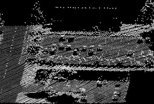
20 Visualization using intensity 39 Visualization using intensity 40 20
21 Calibration of intensity Because intensity values vary according to conditions, they must be calibrated before, e.g., automatic interpretation Range calibration Bidirectional reflectance distribution function (BRDF) calibration Calibration with the help of reference targets 41 Range calibration The range effect of intensity depends on how much the target fills the laser footprint of a single laser beam Intensity weakens proportional to R 2 if a homogenous target fills the full footprint R 3 if a target is linear (e.g. wire) R 4 if a target is an individual large scatterer 42 21
22 BRDF (Bidirectional reflectance distribution function ) 2 Ps 1 BRDF = Pi Ω cosθs P s = Scattered power P i = Incident power Ω = Scattering solid angle Θ s = Angle between scattering direction and surface normal BRDF describes how a surface reflects light Light Θ s Ω Detector 43 Automatic gain control Some laser scanners apply an automatic gain control to data Received energy (intensity) is fit to the range of the receiver during the flight Because data has unpredictable intensity variations, calibration becomes difficult To some extent the effect of the automatic gain control can be removed using calibration targets I = a + a I a I AGC off 1 2 on + 3 AGC =automatic gain control value, I on =intensity value when AGC is on, a i are to be solved on 44 22
 Natural materials, e.g.")
23 Before intensity calibration After intensity calibration Martina Bednjanec 45 Calibration by using reference targets Reference targets with a known reflectance Standard targets: Spectralon by Labsphere Inc (close to a Lambertian surface) Natural materials, e.g., sand or gravel placed on the scene Natural materials that can be found in the field (e.g. football field) True surface reflectance from the intensity observation I r measurement = I measurement standard standard BRDF correction can be combined with a reference target calibration r 46 23


24 Examples from the Finnish Geospatial Research Center Intensity calibration tarps Gravel calibration field Hannu Hyyppä 47 Multispectral laser scanning Optech Titan is the first commercial multispectral airborne laser scanner three active laser beams with independent wavelengths of 532 nm, 1064 nm, and 1550 nm Optech 48 24


 City mapping, 3D models Flood mapping Change")
25 UAV laser scanning (Unmanned aerial vehicle) UAV laser scanners improve flexibility of measurements Flying regulations usually prevent mapping of large areas (in Finland you must have visual contact to drone) Operating costs are lower than with helicopters or airplanes 49 Applications of airborne laser scanning Producing elevation models Forest inventory Mapping of linear features (power lines, roads, railroads etc.) City mapping, 3D models Flood mapping Change detection Mass calculations Basis for several planning tasks Etc
26 Laser scanning process in practice Flight planning and preparations Define the point density Define the flying altitude Choose the laser beam divergence Decide the width of laser scanning strips Define the amount of overlap for laser scanning strips/swaths Timing Good weather Leafs-off or leafs-on? 51 What does frequency mean? Frequency (f ) is the number of occurrences of a repeating event per unit time (wikipedia) If the time period of regularily repeated phenomena (T ) in known, the frequency is 1 f = T 1 Unit is hertz (Hz) Hz = s In other words, one Hz means that regularily repeated phenomena happens once a second 52 26

27 Flying altitude and width of laser scanning strip θ strip width = 2H tan 2 For example, to get the laser scanning strip of 400 m width (at ground), what should the flying height be? The opening angle of the scanner is ± 25 degrees. strip width = H 2 tan θ 2 400m = 428,90m 50 2 tan 2 θ Η 53 Flying altitude and width of laser scanning strip The equation θ strip width = 2H tan 2 is usable also with Palmer scanners (even if its footprint is elliptical), if the angle is measured directly downwards and perpendicularly to the flying direction 54 27
28 How many points (N) we get within one laser scanning sweep? PRF=pulse repetition frequency f scanner =scanning frequency N = PRF f scanner For example, PRF=70 khz and scanning frequency is 80 Hz. How many points we get during one laser scanning sweep? N = 70000Hz 80Hz = 875 points 55 Point density in the across flight line direction dx across = strip width N If we use values from previous examples, we find that distances between points in across flightline direction are 400m dx across = = 0. 46m
29 Point density in the across flight line direction Scanner can produce Z-shaped footprint (oscillating mirror). It can vary, if scanning frequency means one sweep (half of Z- shape) or the situation when mirror is back at the starting position (complete Z-shape) If scanning frequency means complete Z-shape, the result from previous slide must be multiplied by two Note that the point distribution along the Z-shape is not necessarily even (typically point cloud is denser at the sides of laser strips) 57 Point density in the across flight line direction For optical fiber scanners, the across flightline point density is θ dx across = H N 1 For Palmer scanners we can calculate approximation dx across strip width = π N And more accurately.4429h 2 dx across = tan (2SN) + tan N 4 2 (1.41SN) SN=inclination angle of mirror 58 29
30 Point density in the along flight line direction Independent of the flying height Depends on the speed of an aircraft (v) and scanning frequency (f scanner ) v dx = along scanner For example, if the speed of an aircraft is 75 m/s (270 km/h) and scanning frequency is 80 Hz f m 75 dx s along = 0. 94m 80Hz = 59 Distance between flying paths What is a proper distance of flying paths to get desired overlap (s overlap ) of scanning strips s overlap scanning strip distance = scanning strip width For example, if 20% overlap is wanted when the strip width is 400: 20 distance between scanning strips = 400m 1 = 320m
 VRS=Virtual (GPS) Reference")

31 Laser scanning process in practice Preparation of GPS equipments Terrestrial GPS reference station (dgps) VRS=Virtual (GPS) Reference Station, for example gpsnet.fi/ 61 GPS/GNSS Webserver VRS-network has permanent GPS reference stations and data processing centers GPSNet.fi 62 31
32 Laser scanning process in practice Laser data acquisition Flying over the target Collecting of GPS, IMU and laser observations 63 Laser scanning process in practice According to observations the 3D ground coordinates are calculated Position and attitude of laser scanner must be know for each range measurement 64 32
33 Laser scanning process in practice Data quality verification Compare with know ground features Compare overlapping scanning strips (specially with cross strips) Check that data has no unwanted gaps Post-processing of data (next lecture) 65 33
ENY-C2005 Geoinformation in Environmental Modeling Lecture 4b: Laser scanning
 1 ENY-C2005 Geoinformation in Environmental Modeling Lecture 4b: Laser scanning Petri Rönnholm Aalto University 2 Learning objectives To recognize applications of laser scanning To understand principles
CLASSIFICATION OF NONPHOTOGRAPHIC REMOTE SENSORS
 CLASSIFICATION OF NONPHOTOGRAPHIC REMOTE SENSORS PASSIVE ACTIVE DIGITAL CAMERA THERMAL (e.g. TIMS) VIDEO CAMERA MULTI- SPECTRAL SCANNERS VISIBLE & NIR MICROWAVE HYPERSPECTRAL (e.g. AVIRIS) SLAR Real Aperture
Airborne Laser Scanning: Remote Sensing with LiDAR
 Airborne Laser Scanning: Remote Sensing with LiDAR ALS / LIDAR OUTLINE Laser remote sensing background Basic components of an ALS/LIDAR system Two distinct families of ALS systems Waveform Discrete Return
Light Detection and Ranging (LiDAR)
") Light Detection and Ranging (LiDAR) http://code.google.com/creative/radiohead/ Types of aerial sensors passive active 1 Active sensors for mapping terrain Radar transmits microwaves in pulses determines
Light Detection and Ranging (LiDAR) http://code.google.com/creative/radiohead/ Types of aerial sensors passive active 1 Active sensors for mapping terrain Radar transmits microwaves in pulses determines
N.J.P.L.S. An Introduction to LiDAR Concepts and Applications
 N.J.P.L.S. An Introduction to LiDAR Concepts and Applications Presentation Outline LIDAR Data Capture Advantages of Lidar Technology Basics Intensity and Multiple Returns Lidar Accuracy Airborne Laser
Terrestrial GPS setup Fundamentals of Airborne LiDAR Systems, Collection and Calibration. JAMIE YOUNG Senior Manager LiDAR Solutions
 Terrestrial GPS setup Fundamentals of Airborne LiDAR Systems, Collection and Calibration JAMIE YOUNG Senior Manager LiDAR Solutions Topics Terrestrial GPS reference Planning and Collection Considerations
Lecture 11. LiDAR, RADAR
 NRMT 2270, Photogrammetry/Remote Sensing Lecture 11 Calculating the Number of Photos and Flight Lines in a Photo Project LiDAR, RADAR Tomislav Sapic GIS Technologist Faculty of Natural Resources Management
Processing of airborne laser scanning data
 GIS-E1020 From measurements to maps Lecture 8 Processing of airborne laser scanning data Petri Rönnholm Aalto University 1 Learning objectives To realize error sources of Airborne laser scanning To understand
Lidar Sensors, Today & Tomorrow. Christian Sevcik RIEGL Laser Measurement Systems
 Lidar Sensors, Today & Tomorrow Christian Sevcik RIEGL Laser Measurement Systems o o o o Online Waveform technology Stand alone operation no field computer required Remote control through wireless network
Advanced Processing Techniques and Classification of Full-waveform Airborne Laser...
 f j y = f( x) = f ( x) n j= 1 j Advanced Processing Techniques and Classification of Full-waveform Airborne Laser... 89 A summary of the proposed methods is presented below: Stilla et al. propose a method
Airborne LiDAR Data Acquisition for Forestry Applications. Mischa Hey WSI (Corvallis, OR)
") Airborne LiDAR Data Acquisition for Forestry Applications Mischa Hey WSI (Corvallis, OR) WSI Services Corvallis, OR Airborne Mapping: Light Detection and Ranging (LiDAR) Thermal Infrared Imagery 4-Band
Airborne LiDAR Data Acquisition for Forestry Applications Mischa Hey WSI (Corvallis, OR) WSI Services Corvallis, OR Airborne Mapping: Light Detection and Ranging (LiDAR) Thermal Infrared Imagery 4-Band
1. Which diagram best represents the reflection of light from an irregular surface?
 waves 6-2-04 Name 02-JUN-04 1. Which diagram best represents the reflection of light from an irregular surface? 1. 1 3. 3 2. 2 4. 4 2. In a vacuum, a monochromatic beam of light as a frequency of 6.3 X
Homework Set 3 Due Thursday, 07/14
 Homework Set 3 Due Thursday, 07/14 Problem 1 A room contains two parallel wall mirrors, on opposite walls 5 meters apart. The mirrors are 8 meters long. Suppose that one person stands in a doorway, in
LAS extrabytes implementation in RIEGL software WHITEPAPER
 in RIEGL software WHITEPAPER _ Author: RIEGL Laser Measurement Systems GmbH Date: May 25, 2012 Status: Release Pages: 13 All rights are reserved in the event of the grant or the registration of a utility
An Introduction to Lidar & Forestry May 2013
 An Introduction to Lidar & Forestry May 2013 Introduction to Lidar & Forestry Lidar technology Derivatives from point clouds Applied to forestry Publish & Share Futures Lidar Light Detection And Ranging
Light Detection and Ranging (LiDAR) Radiohead House of Cards
 Radiohead House of Cards") Light Detection and Ranging (LiDAR) Radiohead House of Cards http://the-moni-blog.blogspot.com/2009/03/lidar-is-going-mainstream-mtv-baby.html h =? Laser Vision GPS + IMU θ H X a h Types of aerial sensors
Light Detection and Ranging (LiDAR) Radiohead House of Cards http://the-moni-blog.blogspot.com/2009/03/lidar-is-going-mainstream-mtv-baby.html h =? Laser Vision GPS + IMU θ H X a h Types of aerial sensors
Optics Vac Work MT 2008
 Optics Vac Work MT 2008 1. Explain what is meant by the Fraunhofer condition for diffraction. [4] An aperture lies in the plane z = 0 and has amplitude transmission function T(y) independent of x. It is
Airborne Laser Survey Systems: Technology and Applications
 Abstract Airborne Laser Survey Systems: Technology and Applications Guangping HE Lambda Tech International, Inc. 2323B Blue Mound RD., Waukesha, WI-53186, USA Email: he@lambdatech.com As mapping products
A QUALITY ASSESSMENT OF AIRBORNE LASER SCANNER DATA
 A QUALITY ASSESSMENT OF AIRBORNE LASER SCANNER DATA E. Ahokas, H. Kaartinen, J. Hyyppä Finnish Geodetic Institute, Geodeetinrinne 2, 243 Masala, Finland Eero.Ahokas@fgi.fi KEYWORDS: LIDAR, accuracy, quality,
SIMULATED LIDAR WAVEFORMS FOR THE ANALYSIS OF LIGHT PROPAGATION THROUGH A TREE CANOPY
 SIMULATED LIDAR WAVEFORMS FOR THE ANALYSIS OF LIGHT PROPAGATION THROUGH A TREE CANOPY Angela M. Kim and Richard C. Olsen Remote Sensing Center Naval Postgraduate School 1 University Circle Monterey, CA
Chapter 24. Wave Optics
 Chapter 24 Wave Optics Wave Optics The wave nature of light is needed to explain various phenomena Interference Diffraction Polarization The particle nature of light was the basis for ray (geometric) optics
Chapter 8: Physical Optics
 Chapter 8: Physical Optics Whether light is a particle or a wave had puzzled physicists for centuries. In this chapter, we only analyze light as a wave using basic optical concepts such as interference
Chapter 37. Wave Optics
 Chapter 37 Wave Optics Wave Optics Wave optics is a study concerned with phenomena that cannot be adequately explained by geometric (ray) optics. Sometimes called physical optics These phenomena include:
Chapter 37. Interference of Light Waves
 Chapter 37 Interference of Light Waves Wave Optics Wave optics is a study concerned with phenomena that cannot be adequately explained by geometric (ray) optics These phenomena include: Interference Diffraction
THE USE OF TERRESTRIAL LASER SCANNING FOR MEASUREMENTS IN SHALLOW-WATER: CORRECTION OF THE 3D COORDINATES OF THE POINT CLOUD
 Photogrammetry and Remote Sensing Published as: Deruyter, G., Vanhaelst, M., Stal, C., Glas, H., De Wulf, A. (2015). The use of terrestrial laser scanning for measurements in shallow-water: correction
What is it? How does it work? How do we use it?
 What is it? How does it work? How do we use it? Dual Nature http://www.youtube.com/watch?v=dfpeprq7ogc o Electromagnetic Waves display wave behavior o Created by oscillating electric and magnetic fields
Aerial and Mobile LiDAR Data Fusion
 Creating Value Delivering Solutions Aerial and Mobile LiDAR Data Fusion Dr. Srini Dharmapuri, CP, PMP What You Will Learn About LiDAR Fusion Mobile and Aerial LiDAR Technology Components & Parameters Project
Michelson Interferometer
 Michelson Interferometer The Michelson interferometer uses the interference of two reflected waves The third, beamsplitting, mirror is partially reflecting ( half silvered, except it s a thin Aluminum
High Resolution Laserscanning, not only for 3D-City Models
 Lohr 133 High Resolution Laserscanning, not only for 3D-City Models UWE LOHR, Ravensburg ABSTRACT The TopoSys laserscanner system is designed to produce digital elevation models (DEMs) of the environment
Chapter 24. Wave Optics. Wave Optics. The wave nature of light is needed to explain various phenomena
 Chapter 24 Wave Optics Wave Optics The wave nature of light is needed to explain various phenomena Interference Diffraction Polarization The particle nature of light was the basis for ray (geometric) optics
UAS based laser scanning for forest inventory and precision farming
 UAS based laser scanning for forest inventory and precision farming M. Pfennigbauer, U. Riegl, P. Rieger, P. Amon RIEGL Laser Measurement Systems GmbH, 3580 Horn, Austria Email: mpfennigbauer@riegl.com,
Mayden VP of Business Development Surdex Corporation
 Making Sense of Sensors Randy Mayden, Mayden VP of Business Development Surdex Corporation randym@surdex.com EARLYAERIAL PHOTOGRAPHY 2 FIRSTAERIAL CAMERA 3 AERIAL CAMERA SYSTEM DEVELOPMENT Aerial Camera
AP Physics Problems -- Waves and Light
 AP Physics Problems -- Waves and Light 1. 1975-4 (Physical Optics) a. Light of a single wavelength is incident on a single slit of width w. (w is a few wavelengths.) Sketch a graph of the intensity as
Course Outline (1) #6 Data Acquisition for Built Environment. Fumio YAMAZAKI
 #6 Data Acquisition for Built Environment. Fumio YAMAZAKI") AT09.98 Applied GIS and Remote Sensing for Disaster Mitigation #6 Data Acquisition for Built Environment 9 October, 2002 Fumio YAMAZAKI yamazaki@ait.ac.th http://www.star.ait.ac.th/~yamazaki/ Course Outline
AT09.98 Applied GIS and Remote Sensing for Disaster Mitigation #6 Data Acquisition for Built Environment 9 October, 2002 Fumio YAMAZAKI yamazaki@ait.ac.th http://www.star.ait.ac.th/~yamazaki/ Course Outline
Unit 5.C Physical Optics Essential Fundamentals of Physical Optics
 Unit 5.C Physical Optics Essential Fundamentals of Physical Optics Early Booklet E.C.: + 1 Unit 5.C Hwk. Pts.: / 25 Unit 5.C Lab Pts.: / 20 Late, Incomplete, No Work, No Units Fees? Y / N 1. Light reflects
Advanced point cloud processing
 Advanced point cloud processing George Vosselman ITC Enschede, the Netherlands INTERNATIONAL INSTITUTE FOR GEO-INFORMATION SCIENCE AND EARTH OBSERVATION Laser scanning platforms Airborne systems mounted
f. (5.3.1) So, the higher frequency means the lower wavelength. Visible part of light spectrum covers the range of wavelengths from
 So, the higher frequency means the lower wavelength. Visible part of light spectrum covers the range of wavelengths from") Lecture 5-3 Interference and Diffraction of EM Waves During our previous lectures we have been talking about electromagnetic (EM) waves. As we know, harmonic waves of any type represent periodic process
Lecture 5-3 Interference and Diffraction of EM Waves During our previous lectures we have been talking about electromagnetic (EM) waves. As we know, harmonic waves of any type represent periodic process
HAWAII KAUAI Survey Report. LIDAR System Description and Specifications
 HAWAII KAUAI Survey Report LIDAR System Description and Specifications This survey used an Optech GEMINI Airborne Laser Terrain Mapper (ALTM) serial number 06SEN195 mounted in a twin-engine Navajo Piper
Ray Optics I. Last time, finished EM theory Looked at complex boundary problems TIR: Snell s law complex Metal mirrors: index complex
 Phys 531 Lecture 8 20 September 2005 Ray Optics I Last time, finished EM theory Looked at complex boundary problems TIR: Snell s law complex Metal mirrors: index complex Today shift gears, start applying
MODULE 3. FACTORS AFFECTING 3D LASER SCANNING
 MODULE 3. FACTORS AFFECTING 3D LASER SCANNING Learning Outcomes: This module discusses factors affecting 3D laser scanner performance. Students should be able to explain the impact of various factors on
THE RANGER-UAV FEATURES
 THE RANGER-UAV The Ranger Series Ranger-UAV is designed for the most demanding mapping applications, no compromises made. With a 9 meter laser range, this system produces photorealistic 3D point clouds
Downloaded from UNIT 06 Optics
 1 Mark UNIT 06 Optics Q1: A partially plane polarised beam of light is passed through a polaroid. Show graphically the variation of the transmitted light intensity with angle of rotation of the Polaroid.
Snow cover change detection with laser scanning range and brightness measurements
 Snow cover change detection with laser scanning range and brightness measurements Sanna Kaasalainen, Harri Kaartinen, Antero Kukko, Henri Niittymäki Department of Remote Sensing and Photogrammetry 5th
specular diffuse reflection.
 Lesson 8 Light and Optics The Nature of Light Properties of Light: Reflection Refraction Interference Diffraction Polarization Dispersion and Prisms Total Internal Reflection Huygens s Principle The Nature
Chapter 24. Wave Optics. Wave Optics. The wave nature of light is needed to explain various phenomena
 Chapter 24 Wave Optics Wave Optics The wave nature of light is needed to explain various phenomena Interference Diffraction Polarization The particle nature of light was the basis for ray (geometric) optics
Small-footprint Laser Scanning Simulator for System Validation, Error Assessment, and Algorithm Development
 Small-footprint Laser Scanning Simulator for System Validation, Error Assessment, and Algorithm Development Antero Kukko and Juha Hyyppä Abstract Airborne lidar systems have come to be extensively used
Range Sensors (time of flight) (1)
 (1)") Range Sensors (time of flight) (1) Large range distance measurement -> called range sensors Range information: key element for localization and environment modeling Ultrasonic sensors, infra-red sensors
Range Sensors (time of flight) (1) Large range distance measurement -> called range sensors Range information: key element for localization and environment modeling Ultrasonic sensors, infra-red sensors
Unit 5.A Properties of Light Essential Fundamentals of Light 1. Electromagnetic radiation has oscillating magnetic and electric components.
 Unit 5.A Properties of Light Essential Fundamentals of Light 1. Electromagnetic radiation has oscillating magnetic and electric components. Early Booklet E.C.: + 1 Unit 5.A Hwk. Pts.: / 18 Unit 5.A Lab
Chapter 32 Light: Reflection and Refraction. Copyright 2009 Pearson Education, Inc.
 Chapter 32 Light: Reflection and Refraction Units of Chapter 32 The Ray Model of Light Reflection; Image Formation by a Plane Mirror Formation of Images by Spherical Mirrors Index of Refraction Refraction:
Interference. Electric fields from two different sources at a single location add together. The same is true for magnetic fields at a single location.
 Interference Electric fields from two different sources at a single location add together. The same is true for magnetic fields at a single location. Thus, interacting electromagnetic waves also add together.
CALIBRATION PROCEDURES OF THE IMAGING LASER ALTIMETER AND DATA PROCESSING
 CALIBRATION PROCEDURES OF THE IMAGING LASER ALTIMETER AND DATA PROCESSING Karl-Heinz Thiel, Aloysius Wehr Institut für Navigation, Universität Stuttgart Geschwister-Scholl-Str. 24D D-70174 Stuttgart KEYWORDS:
Industrial 2D LASER SCANNER LMS-Q120ii
 LMS-Q120ii Preliminary Datasheet Industrial 2D LASER SCANNER LMS-Q120ii The RIEGL LMS-Q120ii 2D - laser scanner provides accurate noncontact line scanning using a narrow infrared laser beam. The instrument
Learning Objectives LIGHT DETECTION AND RANGING. Sensing. Blacksburg, VA July 24 th 30 th, 2010 LiDAR: Mapping the world in 3-D Page 1
 LiDAR: Mapping the world in 3-D Val Thomas Department of Forest Resources & Environmental Conservation July 29, 2010 Learning Objectives Part 1: Lidar theory What is lidar? How does lidar work? What are
KULLEGG MARIA REGINA BOYS SECONDARY MOSTA HALF-YEARLY EXAMINATIONS 2012/2013. SUBJECT: PHYSICS Form 4 TIME: 1 HR 30 MIN
 KULLEGG MARIA REGINA BOYS SECONDARY MOSTA HALF-YEARLY EXAMINATIONS 2012/2013 SUBJECT: PHYSICS Form 4 TIME: 1 HR 30 MIN NAME : CLASS : INDEX NO : Track 3 Answer ALL questions in the spaces provided on the
RADIOMETRIC CALIBRATION OF ALS INTENSITY
 RADIOMETRIC CALIBRATION OF ALS INTENSITY S. Kaasalainen a, *, J. Hyyppä a, P. Litkey a, H. Hyyppä b, E. Ahokas a, A. Kukko a, and H. Kaartinen a a Finnish Geodetic Institute, Department of Remote Sensing
All forms of EM waves travel at the speed of light in a vacuum = 3.00 x 10 8 m/s This speed is constant in air as well
 Pre AP Physics Light & Optics Chapters 14-16 Light is an electromagnetic wave Electromagnetic waves: Oscillating electric and magnetic fields that are perpendicular to the direction the wave moves Difference
LIDAR MAPPING FACT SHEET
 1. LIDAR THEORY What is lidar? Lidar is an acronym for light detection and ranging. In the mapping industry, this term is used to describe an airborne laser profiling system that produces location and
Light: Geometric Optics
 Light: Geometric Optics The Ray Model of Light Light very often travels in straight lines. We represent light using rays, which are straight lines emanating from an object. This is an idealization, but
Red Orange the reflected ray. Yellow Green and the normal. Blue Indigo line. Colours of visible reflection
 distance the carrying the moves away from rest position Brightness Loudness The angle between the incident ray and the normal line Amplitude Amplitude of a light Amplitude of a sound incidence Angle between
FLAP P6.2 Rays and geometrical optics COPYRIGHT 1998 THE OPEN UNIVERSITY S570 V1.1
 F1 The ray approximation in optics assumes that light travels from one point to another along a narrow path called a ray that may be represented by a directed line (i.e. a line with an arrow on it). In
2011 Optical Science & Engineering PhD Qualifying Examination Optical Sciences Track: Advanced Optics Time allowed: 90 minutes
 2011 Optical Science & Engineering PhD Qualifying Examination Optical Sciences Track: Advanced Optics Time allowed: 90 minutes Answer all four questions. All questions count equally. 3(a) A linearly polarized
Gaussian Beam Calculator for Creating Coherent Sources
 Gaussian Beam Calculator for Creating Coherent Sources INTRODUCTION Coherent sources are represented in FRED using a superposition of Gaussian beamlets. The ray grid spacing of the source is used to determine
Past Paper Questions Waves
 Past Paper Questions Waves Name 1. Explain the differences between an undamped progressive transverse wave and a stationary transverse wave, in terms of amplitude, (ii) phase and (iii) energy transfer.
Physical Optics. You can observe a lot just by watching. Yogi Berra ( )
") Physical Optics You can observe a lot just by watching. Yogi Berra (1925-2015) OBJECTIVES To observe some interference and diffraction phenomena with visible light. THEORY In a previous experiment you
Physical Optics You can observe a lot just by watching. Yogi Berra (1925-2015) OBJECTIVES To observe some interference and diffraction phenomena with visible light. THEORY In a previous experiment you
OPSE FINAL EXAM Fall CLOSED BOOK. Two pages (front/back of both pages) of equations are allowed.
 of equations are allowed.") CLOSED BOOK. Two pages (front/back of both pages) of equations are allowed. YOU MUST SHOW YOUR WORK. ANSWERS THAT ARE NOT JUSTIFIED WILL BE GIVEN ZERO CREDIT. ALL NUMERICAL ANSERS MUST HAVE UNITS INDICATED.
CLOSED BOOK. Two pages (front/back of both pages) of equations are allowed. YOU MUST SHOW YOUR WORK. ANSWERS THAT ARE NOT JUSTIFIED WILL BE GIVEN ZERO CREDIT. ALL NUMERICAL ANSERS MUST HAVE UNITS INDICATED.
1. LiDAR System Description and Specifications
 High Point Density LiDAR Survey of Mayapan, MX PI: Timothy S. Hare, Ph.D. Timothy S. Hare, Ph.D. Associate Professor of Anthropology Institute for Regional Analysis and Public Policy Morehead State University
EXTRACTING SURFACE FEATURES OF THE NUECES RIVER DELTA USING LIDAR POINTS INTRODUCTION
 EXTRACTING SURFACE FEATURES OF THE NUECES RIVER DELTA USING LIDAR POINTS Lihong Su, Post-Doctoral Research Associate James Gibeaut, Associate Research Professor Harte Research Institute for Gulf of Mexico
RIEGL VQ 880 G Laser Scanner System for Topo Bathymetric Surveying. IR laser scanner channel OCTOBER 2015
 RIEGL VQ 880 G Laser Scanner System for Topo Bathymetric Surveying with NEW optional IR laser scanner channel OCTOBER 2015 VQ 880 G Highlights excellently suited for combined hydrographic and topographic
Chapter 3. Physical phenomena: plane parallel plate. This chapter provides an explanation about how rays of light physically behave when
 Chapter 3 Physical phenomena: plane parallel plate This chapter provides an explanation about how rays of light physically behave when propagating through different medium (different index of refraction).
LIGHT. Speed of light Law of Reflection Refraction Snell s Law Mirrors Lenses
 LIGHT Speed of light Law of Reflection Refraction Snell s Law Mirrors Lenses Light = Electromagnetic Wave Requires No Medium to Travel Oscillating Electric and Magnetic Field Travel at the speed of light
Unit 9 Light & Optics
 Unit 9 Light & Optics 1 A quick review of the properties of light. Light is a form of electromagnetic radiation Light travels as transverse waves having wavelength and frequency. fλ=c The velocity of EMR
Experiment 5: Polarization and Interference
 Experiment 5: Polarization and Interference Nate Saffold nas2173@columbia.edu Office Hour: Mondays, 5:30PM-6:30PM @ Pupin 1216 INTRO TO EXPERIMENTAL PHYS-LAB 1493/1494/2699 Introduction Outline: Review
Experiment 8 Wave Optics
 Physics 263 Experiment 8 Wave Optics In this laboratory, we will perform two experiments on wave optics. 1 Double Slit Interference In two-slit interference, light falls on an opaque screen with two closely
Electricity & Optics
 Physics 24100 Electricity & Optics Lecture 27 Chapter 33 sec. 7-8 Fall 2017 Semester Professor Koltick Clicker Question Bright light of wavelength 585 nm is incident perpendicularly on a soap film (n =
Rendering Smoke & Clouds
 Rendering Smoke & Clouds Game Design Seminar 2007 Jürgen Treml Talk Overview 1. Introduction to Clouds 2. Virtual Clouds based on physical Models 1. Generating Clouds 2. Rendering Clouds using Volume Rendering
Chapter 24. Wave Optics
 Chapter 24 Wave Optics Wave Optics The wave nature of light is needed to explain various phenomena Interference Diffraction Polarization The particle nature of light was the basis for ray (geometric) optics
GEOG 4110/5100 Advanced Remote Sensing Lecture 4
 GEOG 4110/5100 Advanced Remote Sensing Lecture 4 Geometric Distortion Relevant Reading: Richards, Sections 2.11-2.17 Review What factors influence radiometric distortion? What is striping in an image?
Leica - Airborne Digital Sensors (ADS80, ALS60) Update / News in the context of Remote Sensing applications
 Update / News in the context of Remote Sensing applications") Luzern, Switzerland, acquired with GSD=5 cm, 2008. Leica - Airborne Digital Sensors (ADS80, ALS60) Update / News in the context of Remote Sensing applications Arthur Rohrbach, Sensor Sales Dir Europe,
Luzern, Switzerland, acquired with GSD=5 cm, 2008. Leica - Airborne Digital Sensors (ADS80, ALS60) Update / News in the context of Remote Sensing applications Arthur Rohrbach, Sensor Sales Dir Europe,
Chapter 1: Overview. Photogrammetry: Introduction & Applications Photogrammetric tools:
 Chapter 1: Overview Photogrammetry: Introduction & Applications Photogrammetric tools: Rotation matrices Photogrammetric point positioning Photogrammetric bundle adjustment This chapter will cover the
10/5/09 1. d = 2. Range Sensors (time of flight) (2) Ultrasonic Sensor (time of flight, sound) (1) Ultrasonic Sensor (time of flight, sound) (2) 4.1.
 (2) Ultrasonic Sensor (time of flight, sound) (1) Ultrasonic Sensor (time of flight, sound) (2) 4.1.") Range Sensors (time of flight) (1) Range Sensors (time of flight) (2) arge range distance measurement -> called range sensors Range information: key element for localization and environment modeling Ultrasonic
Range Sensors (time of flight) (1) Range Sensors (time of flight) (2) arge range distance measurement -> called range sensors Range information: key element for localization and environment modeling Ultrasonic
Supplementary Figure 1 Optimum transmissive mask design for shaping an incident light to a desired
 Supplementary Figure 1 Optimum transmissive mask design for shaping an incident light to a desired tangential form. (a) The light from the sources and scatterers in the half space (1) passes through the
Physics Midterm I
 Phys121 - February 6, 2009 1 Physics 121 - Midterm I Last Name First Name Student Number Signature Tutorial T.A. (circle one): Ricky Chu Firuz Demir Maysam Emadi Alireza Jojjati Answer ALL 10 questions.
Second Year Optics 2017 Problem Set 1
 Second Year Optics 2017 Problem Set 1 Q1 (Revision of first year material): Two long slits of negligible width, separated by a distance d are illuminated by monochromatic light of wavelength λ from a point
To see how a sharp edge or an aperture affect light. To analyze single-slit diffraction and calculate the intensity of the light
 Diffraction Goals for lecture To see how a sharp edge or an aperture affect light To analyze single-slit diffraction and calculate the intensity of the light To investigate the effect on light of many
Chapter 24. Wave Optics
 Chapter 24 Wave Optics hitt1 An upright object is located a distance from a convex mirror that is less than the mirror's focal length. The image formed by the mirror is (1) virtual, upright, and larger
MULTISPECTRAL MAPPING
 VOLUME 5 ISSUE 1 JAN/FEB 2015 MULTISPECTRAL MAPPING 8 DRONE TECH REVOLUTION Forthcoming order of magnitude reduction in the price of close-range aerial scanning 16 HANDHELD SCANNING TECH 32 MAX MATERIAL,
Mapping Project Report Table of Contents
 LiDAR Estimation of Forest Leaf Structure, Terrain, and Hydrophysiology Airborne Mapping Project Report Principal Investigator: Katherine Windfeldt University of Minnesota-Twin cities 115 Green Hall 1530
LiDAR Remote Sensing Data Collection: Yaquina and Elk Creek Watershed, Leaf-On Acquisition
 LiDAR Remote Sensing Data Collection: Yaquina and Elk Creek Watershed, Leaf-On Acquisition Submitted by: 4605 NE Fremont, Suite 211 Portland, Oregon 97213 April, 2006 Table of Contents LIGHT DETECTION
3 - SYNTHETIC APERTURE RADAR (SAR) SUMMARY David Sandwell, SIO 239, January, 2008
 SUMMARY David Sandwell, SIO 239, January, 2008") 1 3 - SYNTHETIC APERTURE RADAR (SAR) SUMMARY David Sandwell, SIO 239, January, 2008 Fraunhoffer diffraction To understand why a synthetic aperture in needed for microwave remote sensing from orbital altitude
1 3 - SYNTHETIC APERTURE RADAR (SAR) SUMMARY David Sandwell, SIO 239, January, 2008 Fraunhoffer diffraction To understand why a synthetic aperture in needed for microwave remote sensing from orbital altitude
About LIDAR Data. What Are LIDAR Data? How LIDAR Data Are Collected
 1 of 6 10/7/2006 3:24 PM Project Overview Data Description GIS Tutorials Applications Coastal County Maps Data Tools Data Sets & Metadata Other Links About this CD-ROM Partners About LIDAR Data What Are
Option G 1: Refraction
 Name: Date: Option G 1: Refraction 1. The table below relates to the electromagnetic spectrum. Complete the table by stating the name of the region of the spectrum and the name of a possible source of
Optics: Laser Light Show Student Advanced Version
 Optics: Laser Light Show Student Advanced Version In this lab, you will explore the behavior of light. You will observe reflection and refraction of a laser beam in jello, and use a diffraction pattern
ratio of the volume under the 2D MTF of a lens to the volume under the 2D MTF of a diffraction limited
 SUPPLEMENTARY FIGURES.9 Strehl ratio (a.u.).5 Singlet Doublet 2 Incident angle (degree) 3 Supplementary Figure. Strehl ratio of the singlet and doublet metasurface lenses. Strehl ratio is the ratio of
Phy 133 Section 1: f. Geometric Optics: Assume the rays follow straight lines. (No diffraction). v 1 λ 1. = v 2. λ 2. = c λ 2. c λ 1.
. v 1 λ 1. = v 2. λ 2. = c λ 2. c λ 1.") Phy 133 Section 1: f Geometric Optics: Assume the rays follow straight lines. (No diffraction). Law of Reflection: θ 1 = θ 1 ' (angle of incidence = angle of reflection) Refraction = bending of a wave
Phy 133 Section 1: f Geometric Optics: Assume the rays follow straight lines. (No diffraction). Law of Reflection: θ 1 = θ 1 ' (angle of incidence = angle of reflection) Refraction = bending of a wave
Chapter 2: Wave Optics
 Chapter : Wave Optics P-1. We can write a plane wave with the z axis taken in the direction of the wave vector k as u(,) r t Acos tkzarg( A) As c /, T 1/ and k / we can rewrite the plane wave as t z u(,)
AP* Optics Free Response Questions
 AP* Optics Free Response Questions 1978 Q5 MIRRORS An object 6 centimeters high is placed 30 centimeters from a concave mirror of focal length 10 centimeters as shown above. (a) On the diagram above, locate
Integrated Multi-Source LiDAR and Imagery
 Figure 1: AirDaC aerial scanning system Integrated Multi-Source LiDAR and Imagery The derived benefits of LiDAR scanning in the fields of engineering, surveying, and planning are well documented. It has
LiDAR data pre-processing for Ghanaian forests biomass estimation. Arbonaut, REDD+ Unit, Joensuu, Finland
 LiDAR data pre-processing for Ghanaian forests biomass estimation Arbonaut, REDD+ Unit, Joensuu, Finland Airborne Laser Scanning principle Objectives of the research Prepare the laser scanning data for
Physics 202, Lecture 23
 Physics 202, Lecture 23 Today s Topics Lights and Laws of Geometric Optics Nature of Light Reflection and Refraction Law of Reflection Law of Refraction Index of Reflection, Snell s Law Total Internal
High spatial resolution measurement of volume holographic gratings
 High spatial resolution measurement of volume holographic gratings Gregory J. Steckman, Frank Havermeyer Ondax, Inc., 8 E. Duarte Rd., Monrovia, CA, USA 9116 ABSTRACT The conventional approach for measuring