101-1 Under-Graduate Project Digital IC Design Flow
|
|
|
- Ethelbert Job Butler
- 5 years ago
- Views:
Transcription


1 101-1 Under-Graduate Project Digital IC Design Flow Speaker: Ming-Chun Hsiao Adviser: Prof. An-Yeu Wu Date: 2012/9/25 ACCESS IC LAB

2 Outline Introduction to Integrated Circuit IC Design Flow Verilog HDL concept Verilog Simulator P. 2
. Logic capacity doubles per IC every 18 months (1975).")
3 Moore s Law: Driving Technology Advances Logic capacity doubles per IC at regular intervals (1965). Logic capacity doubles per IC every 18 months (1975). P. 3

4 Chips Sizes Source: IBM and Dataquest P. 4
,")
5 Design Productivity Crisis Design gap Human factors may limit design more than technology. Keys to solve the productivity crisis: Design techniques: hierarchical design, SoC design (IP reuse, platform-based design), etc. CAD: algorithms & methodology P. 5
6 Increasing Processing Power Very high performance circuits in today s technologies. Gate delays: ~27ps for a 2-input Nand in CU11 Operating frequencies: Up to 500MHz for SoC/Asic Over 1GHz for custom designs The increase in speed/performance of circuits allowed blocks to be reused without having to be redesigned and tuned for each application. Enhanced Design Tools and Techniques Although not enough to close the design gap, tools are essential for the design of today s high-performance chips P. 6
 Possibly with placement information Hard IP/Core Due to their complexity, they are provided as a blackbox (GDSII). Ex.")
7 IP / Cores Soft IP/Core Delivered as RTL verilog or VHDL source code with synthesis script Customers are responsible for synthesis, timing closure, and all front-end processing Firm IP/Core Delivered as a netlist to be included in customer s netlist (with don't touch attribute) Possibly with placement information Hard IP/Core Due to their complexity, they are provided as a blackbox (GDSII). Ex. Processors, analog cores, PLLs Usually very tight timing constraints. Internal views not be alterable or visible to the customer P. 7
")
8 Changes in the Nature of IC Design (IEEE Spectrum Nov,1996) P. 8

9 Chasing the Design Gap P. 9
10 Evolution of Silicon Design Source: Surviving the SoC revolution A Guide to Platform-based Design, Henry Chang et al, Kluwer Academic Publishers, 1999 P. 10

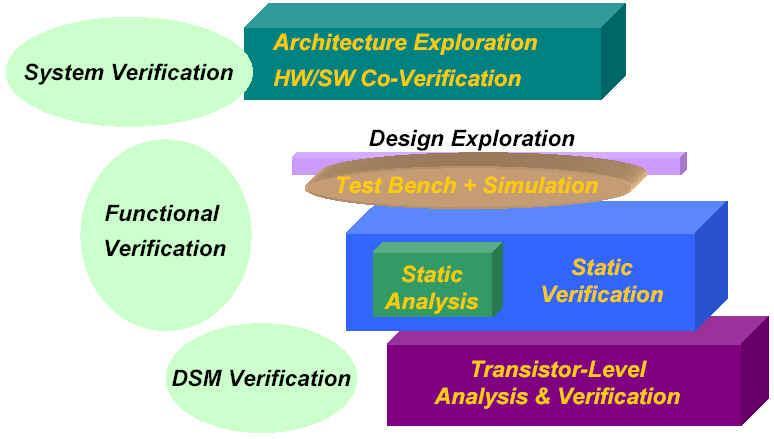
11 Methodology Analysis and Verification P. 11
12 Outline Introduction to Integrated Circuit IC Design Flow Verilog HDL concept Verilog Simulator P. 12


13 Idea IC Design and Implementation Design P. 13


14 Design Specification Design Flow Pre-Synthesis Sign-Off Back End Cell Placement, Scan Chain & Clock Tree Insertion, Cell Routing Design Partition Synthesize and Map Gate-Level Netlist Verify Physical & Electrical Design Rules Design Entry-Verilog Behavioral Modeling Post-Synthesis Design Validation Extract Parasitics Simulation/Functional Verification Post-Synthesis Timing Verification Post-Layout Timing Verification Design Integration & Verification Test Generation & Fault Simulation Design Sign-Off Front End Production-Ready Masks P. 14
15 System Specification From CIC P. 15

16 Algorithm Mapping System Level RTL Level From CIC P. 16

17 Gate and Circuit Level Design From CIC P. 17


18 Physical Design From CIC P. 18

19 Behavioral Model Increasing behavioral abstraction System concept Algorithm Architecture Register Transfer Level Gate Level Transistor Level Increasing detailed realization & complexity P. 19
20 Design Domain Behavioral level of abstraction Abstract Design Model Domain Structural Physical System Algorithm RTL Gate Switch Architecture Design Verification Structural Design Verification Architecture Synthesis Logic Design Verification RTL level Synthesis Logic level Synthesis Layout Design P. 20
21 Outline Introduction to Integrated Circuit IC Design Flow Verilog HDL concept Verilog Simulator P. 21
22 Introduction to HDL HDL Hardware Description Language Why use an HDL? Hardware is becoming very difficult to design directly HDL is easier and cheaper to explore different design options Reduce time and cost P. 22

23 Features Verilog HDL HDL has high-level programming language constructs and constructs to describe the connectivity of your circuit. Ability to mix different levels of abstraction freely One language for all aspects of design, test, and verification Functionality as well as timing Concurrency perform Support timing simulation P. 23
24 Compared to VHDL Verilog and VHDL are comparable languages VHDL has a slightly wider scope System-level modeling Exposes even more discrete-event machinery VHDL is better-behaved Fewer sources of non-determinism (e.g., no shared variables???) VHDL is harder to simulate quickly VHDL has fewer built-in facilities for hardware modeling VHDL is a much more verbose language Most examples don t fit on slides P. 24
25 The Verilog Language Originally a modeling language for a very efficient event-driven digital logic simulator Later pushed into use as a specification language for logic synthesis Now, one of the two most commonly-used languages in digital hardware design (VHDL is the other) Combines structural and behavioral modeling styles P. 25
26 Different Levels of Abstraction Architectural / Algorithmic A model that implements a design algorithm in high-level language constructs Register Transfer Logic (RTL) A model that describes the flow of data between registers and how a design process these data. Gate A model that describe the logic gates and the interconnections between them. Switch A model that describes the transistors and the interconnections between them. P. 26
27 Verilog HDL Behavior Language Structural and procedural like the C programming language Used to describe algorithm level and RTL level Verilog models Key features Procedural constructs for conditional, if-else, case, and looping operations. Arithmetic, logical, bit-wise, and reduction operations for expressions. Timing control. P. 27
28 Verilog HDL Structural Language Used to describe gate-level and switch-level circuits. Key features A complete set set of combinational primitives Support primitive gate delay specification Support primitive gate output strength specification P. 28
29 Language Conventions (1/2) Case-sensitivity Verilog is case-sensitive. Some simulators are case-insensitive Advice: - Don t use case-sensitive feature! Keywords are lower case Different names must be used for different items within the same scope Identifier alphabet: Upper and lower case alphabeticals: a~z A~Z Decimal digits: 0~9 Underscore: _ P. 29
30 Language Conventions (2/2) Maximum of 1024 characters in identifier First character not a digit Statement terminated by ; Free format within statement except for within quotes Comments: All characters after // in a line are treated as a comment Multi-line comments begin with /* and end with */ Compiler directives begin with // synopsys XXX Built-in system tasks or functions begin with $ Strings enclosed in double quotes and must be on a single line Strings P. 30
31 Design Encapsulation Encapsulate structural and functional details in a module module my_design (ports_list);... // Declarations of ports go here... // Structural and functional details go here endmodule Encapsulation makes the model available for instantiation in other modules P. 31
32 Port Declaration Three port types Input port input a; Output port output b; Bi-direction port inout c; reg or net input net inout module net net output reg or net Port list module full_add (S, CO, A, B, CI) ; output S, CO ; input A, B, CI ; net Port Declaration --- function description --- endmodule P. 32
33 Two Main Data Types Nets represent connections between things Do not hold their value Take their value from a driver such as a gate or other module Cannot be assigned in an initial or always block Regs represent data storage Behave exactly like memory in a computer Hold their value until explicitly assigned in an initial or always block Never connected to something Can be used to model latches, flip-flops, etc., but do not correspond exactly Shared variables with all their attendant problems P. 33
34 Primitive Cells Primitives are simple modules Verilog build-in primitive gate not, buf: Variable outputs, single input (last port) and, or, buf, xor, nand, nor, xnor: Single outputs (first port), variable inputs module full_add (S, CO, A, B, CI) ; --- port Declaration --- wire net1, net2, net3; xor U0(S,A,B,CI); and U1(net1, A, B); and U2(net2, B, CI); and U3(net3, CI, A); or U4(CO, net1, net2, net3); endmodule P. 34
35 How Are Simulators Used? Testbench generates stimulus and checks response Coupled to model of the system Pair is run simultaneously Stimulus Testbench System Model Result checker Response P. 35
36 Example: Testbench module t_full_add(); wire sum, c_out; reg a, b, cin; // Storage containers for stimulus waveforms full_add M1 (sum, c_out, a, b, cin); //UUT initial begin // Time Out #200 $finish; // Stopwatch end initial begin // Stimulus patterns #10 a = 0; b = 0; cin = 0; // Statements execute in sequence #10 a = 0; b = 1; cin = 0; #10 a = 1; b = 0; cin = 0; #10 a = 1; b = 1; cin = 0; #10 a = 0; b = 0; cin = 1; #10 a = 0; b = 1; cin = 1; #10 a = 1; b = 0; cin = 1; #10 a = 1; b = 1; cin = 1; end endmodule P. 36
37 Outline Introduction to Integrated Circuit IC Design Flow Verilog HDL concept Verilog Simulator P. 37

38 Verilog Simulator P. 38

39 Event-Driven Simulation A change in the value of a signal (variable) during simulation is referred to as an event Spice-like analog simulation is impractical for VLSI circuits Event-driven simulators update logic values only when signals change P. 39

40 Styles Structural - instantiation of primitives and modules RTL/Dataflow - continuous assignments Behavioral - procedural assignments P. 40
41 Structural Modeling When Verilog was first developed (1984) most logic simulators operated on netlists Netlist: list of gates and how they re connected A natural representation of a digital logic circuit Not the most convenient way to express test benches P. 41
42 Behavioral Modeling A much easier way to write testbenches Also good for more abstract models of circuits Easier to write Simulates faster More flexible Provides sequencing Verilog succeeded in part because it allowed both the model and the testbench to be described together P. 42
; module half_add (S, C, X, Y); output S, C ; input X, Y ; xor (S, X, Y) ; and (C, X, Y) ; endmodule or P1 (CO, N3, N2); endmodule P.")
43 Style 1 - Structural module full_add (S, CO, A, B, CI) ; output S, CO ; input A, B, CI ; wire N1, N2, N3; half_add HA1 (N1, N2, A, B), HA2 (S, N3, N1, CI); module half_add (S, C, X, Y); output S, C ; input X, Y ; xor (S, X, Y) ; and (C, X, Y) ; endmodule or P1 (CO, N3, N2); endmodule P. 43
44 Style 2 Dataflow/RTL module fa_rtl (S, CO, A, B, CI) ; output S, CO ; input A, B, CI ; assign S = A ^ B ^ CI; assign CO = A & B A & CI B & CI; //continuous assignment //continuous assignment endmodule P. 44
 ; output S, CO ; input A, B, CI ; reg S,")
 //; begin S <= A ^ B ^")

45 Style 3 Behavioral module fa_bhv (S, CO, A, B, CI) ; output S, CO ; input A, B, CI ; reg S, CO; // required to hold values between events. always@(a or B or CI) //; begin S <= A ^ B ^ CI; // procedural assignment CO <= A & B A & CI B & CI; // procedural assignment end endmodule P. 45
46 How Verilog Is Used Virtually every ASIC is designed using either Verilog or VHDL (a similar language) Behavioral modeling with some structural elements Synthesis subset Can be translated using Synopsys Design Compiler or others into a netlist Design written in Verilog Simulated to death to check functionality Synthesized (netlist generated) Static timing analysis to check timing P. 46

47 Verilog-HDL Simulators Mentor Graphics ModelSim Cadence Verilog-XL NC-Verilog P. 47
Synthesizable Verilog
 Synthesizable Verilog Courtesy of Dr. Edwards@Columbia, and Dr. Franzon@NCSU http://csce.uark.edu +1 (479) 575-6043 yrpeng@uark.edu Design Methodology Structure and Function (Behavior) of a Design HDL
Speaker: Shao-Wei Feng Adviser: Prof. An-Yeu Wu Date: 2010/09/28
 99-1 Under-Graduate Project Verilog Simulation & Debugging Tools Speaker: Shao-Wei Feng Adviser: Prof. An-Yeu Wu Date: 2010/09/28 ACCESS IC LAB Outline Basic Concept of Verilog HDL Gate Level Modeling
EEL 4783: Hardware/Software Co-design with FPGAs
 EEL 4783: Hardware/Software Co-design with FPGAs Lecture 8: Short Introduction to Verilog * Prof. Mingjie Lin * Beased on notes of Turfts lecture 1 Overview Recap + Questions? What is a HDL? Why do we
The Verilog Language COMS W Prof. Stephen A. Edwards Fall 2002 Columbia University Department of Computer Science
 The Verilog Language COMS W4995-02 Prof. Stephen A. Edwards Fall 2002 Columbia University Department of Computer Science The Verilog Language Originally a modeling language for a very efficient event-driven
Lab. Course Goals. Topics. What is VLSI design? What is an integrated circuit? VLSI Design Cycle. VLSI Design Automation
 Course Goals Lab Understand key components in VLSI designs Become familiar with design tools (Cadence) Understand design flows Understand behavioral, structural, and physical specifications Be able to
Verilog. What is Verilog? VHDL vs. Verilog. Hardware description language: Two major languages. Many EDA tools support HDL-based design
 Verilog What is Verilog? Hardware description language: Are used to describe digital system in text form Used for modeling, simulation, design Two major languages Verilog (IEEE 1364), latest version is
Verilog HDL Introduction
 EEE3050 Theory on Computer Architectures (Spring 2017) Prof. Jinkyu Jeong Verilog HDL Introduction 2017.05.14 TA 이규선 (GYUSUN LEE) / 안민우 (MINWOO AHN) Modules The Module Concept Basic design unit Modules
Hardware Design Environments. Dr. Mahdi Abbasi Computer Engineering Department Bu-Ali Sina University
 Hardware Design Environments Dr. Mahdi Abbasi Computer Engineering Department Bu-Ali Sina University Outline Welcome to COE 405 Digital System Design Design Domains and Levels of Abstractions Synthesis
תכן חומרה בשפת VERILOG הפקולטה להנדסה
 תכן חומרה בשפת VERILOG סמסטר ב' תשע"ג משה דורון מרצה: מתרגלים: אריאל בורג, חג'ג' חן הפקולטה להנדסה 1 Course Topics - Outline Lecture 1 - Introduction Lecture 2 - Lexical conventions Lecture 3 - Data types
What is Verilog HDL? Lecture 1: Verilog HDL Introduction. Basic Design Methodology. What is VHDL? Requirements
 What is Verilog HDL? Lecture 1: Verilog HDL Introduction Verilog Hardware Description Language(HDL)? A high-level computer language can model, represent and simulate digital design Hardware concurrency
Introduction to Verilog
 Introduction to Verilog COE 202 Digital Logic Design Dr. Muhamed Mudawar King Fahd University of Petroleum and Minerals Presentation Outline Hardware Description Language Logic Simulation versus Synthesis
Verilog Tutorial (Structure, Test)
") Digital Circuit Design and Language Verilog Tutorial (Structure, Test) Chang, Ik Joon Kyunghee University Hierarchical Design Top-down Design Methodology Bottom-up Design Methodology Module START Example)
Digital Circuit Design and Language Verilog Tutorial (Structure, Test) Chang, Ik Joon Kyunghee University Hierarchical Design Top-down Design Methodology Bottom-up Design Methodology Module START Example)
Introduction to Verilog HDL. Verilog 1
 Introduction to HDL Hardware Description Language (HDL) High-Level Programming Language Special constructs to model microelectronic circuits Describe the operation of a circuit at various levels of abstraction
FPGA Design Challenge :Techkriti 14 Digital Design using Verilog Part 1
 FPGA Design Challenge :Techkriti 14 Digital Design using Verilog Part 1 Anurag Dwivedi Digital Design : Bottom Up Approach Basic Block - Gates Digital Design : Bottom Up Approach Gates -> Flip Flops Digital
Introduction to Verilog HDL
 Introduction to Verilog HDL Ben Abdallah Abderazek National University of Electro-communications, Tokyo, Graduate School of information Systems May 2004 04/09/08 1 What you will understand after having
Hardware description languages
 Specifying digital circuits Schematics (what we ve done so far) Structural description Describe circuit as interconnected elements Build complex circuits using hierarchy Large circuits are unreadable Hardware
Speaker: Kayting Adviser: Prof. An-Yeu Wu Date: 2009/11/23
 98-1 Under-Graduate Project Synthesis of Combinational Logic Speaker: Kayting Adviser: Prof. An-Yeu Wu Date: 2009/11/23 What is synthesis? Outline Behavior Description for Synthesis Write Efficient HDL
Advanced Digital Design Using FPGA. Dr. Shahrokh Abadi
 Advanced Digital Design Using FPGA Dr. Shahrokh Abadi 1 Venue Computer Lab: Tuesdays 10 12 am (Fixed) Computer Lab: Wednesday 10-12 am (Every other odd weeks) Note: Due to some unpredicted problems with
Advanced Digital Design with the Verilog HDL
 Copyright 2001, 2003 MD Ciletti 1 Advanced Digital Design with the Verilog HDL M. D. Ciletti Department of Electrical and Computer Engineering University of Colorado Colorado Springs, Colorado ciletti@vlsic.uccs.edu
A Brief Introduction to Verilog Hardware Definition Language (HDL)
") www.realdigital.org A Brief Introduction to Verilog Hardware Definition Language (HDL) Forward Verilog is a Hardware Description language (HDL) that is used to define the structure and/or behavior of digital
www.realdigital.org A Brief Introduction to Verilog Hardware Definition Language (HDL) Forward Verilog is a Hardware Description language (HDL) that is used to define the structure and/or behavior of digital
Online Verilog Resources
 EECS 427 Discussion 6: Verilog HDL Reading: Many references EECS 427 F08 Discussion 6 1 Online Verilog Resources ASICs the book, Ch. 11: http://www.ge.infn.it/~pratolo/verilog/verilogtutorial.pdf it/ pratolo/verilog/verilogtutorial
Spiral 1 / Unit 4 Verilog HDL. Digital Circuit Design Steps. Digital Circuit Design OVERVIEW. Mark Redekopp. Description. Verification.
 1-4.1 1-4.2 Spiral 1 / Unit 4 Verilog HDL Mark Redekopp OVERVIEW 1-4.3 1-4.4 Digital Circuit Design Steps Digital Circuit Design Description Design and computer-entry of circuit Verification Input Stimulus
N-input EX-NOR gate. N-output inverter. N-input NOR gate
 Hardware Description Language HDL Introduction HDL is a hardware description language used to design and document electronic systems. HDL allows designers to design at various levels of abstraction. It
14:332:231 DIGITAL LOGIC DESIGN. Hardware Description Languages
 14:332:231 DIGITAL LOGIC DESIGN Ivan Marsic, Rutgers University Electrical & Computer Engineering Fall 2013 Lecture #22: Introduction to Verilog Hardware Description Languages Basic idea: Language constructs
Synthesis of Combinational and Sequential Circuits with Verilog
 Synthesis of Combinational and Sequential Circuits with Verilog What is Verilog? Hardware description language: Are used to describe digital system in text form Used for modeling, simulation, design Two
THE DESIGNER'S GUIDE TO VERILOG-AMS First Edition June 2004
 THE DESIGNER'S GUIDE TO VERILOG-AMS First Edition June 2004 KENNETH S. KUNDERT Cadence Design Systems OLAF ZINKE Cadence Design Systems k4 Kluwer Academic Publishers Boston/Dordrecht/London Chapter 1 Introduction
EECS150 - Digital Design Lecture 5 - Verilog Logic Synthesis
 EECS150 - Digital Design Lecture 5 - Verilog Logic Synthesis Jan 31, 2012 John Wawrzynek Spring 2012 EECS150 - Lec05-verilog_synth Page 1 Outline Quick review of essentials of state elements Finite State
Lecture 15: System Modeling and Verilog
 Lecture 15: System Modeling and Verilog Slides courtesy of Deming Chen Intro. VLSI System Design Outline Outline Modeling Digital Systems Introduction to Verilog HDL Use of Verilog HDL in Synthesis Reading
CAD for VLSI Design - I. Lecture 21 V. Kamakoti and Shankar Balachandran
 CAD for VLSI Design - I Lecture 21 V. Kamakoti and Shankar Balachandran Overview of this Lecture Understanding the process of Logic synthesis Logic Synthesis of HDL constructs Logic Synthesis What is this?
Evolution of CAD Tools & Verilog HDL Definition
 Evolution of CAD Tools & Verilog HDL Definition K.Sivasankaran Assistant Professor (Senior) VLSI Division School of Electronics Engineering VIT University Outline Evolution of CAD Different CAD Tools for
Lecture 1: Introduction Course arrangements Recap of basic digital design concepts EDA tool demonstration
 TKT-1426 Digital design for FPGA, 6cp Fall 2011 http://www.tkt.cs.tut.fi/kurssit/1426/ Tampere University of Technology Department of Computer Systems Waqar Hussain Lecture Contents Lecture 1: Introduction
Tutorial on Verilog HDL
 Tutorial on Verilog HDL HDL Hardware Description Languages Widely used in logic design Verilog and VHDL Describe hardware using code Document logic functions Simulate logic before building Synthesize code
Digital System Design Lecture 2: Design. Amir Masoud Gharehbaghi
 Digital System Design Lecture 2: Design Amir Masoud Gharehbaghi amgh@mehr.sharif.edu Table of Contents Design Methodologies Overview of IC Design Flow Hardware Description Languages Brief History of HDLs
Schematic design. Gate level design. 0 EDA (Electronic Design Assistance) 0 Classical design. 0 Computer based language
 0 Classical design. 0 Computer based language") 1 / 15 2014/11/20 0 EDA (Electronic Design Assistance) 0 Computer based language 0 HDL (Hardware Description Language) 0 Verilog HDL 0 Created by Gateway Design Automation Corp. in 1983 First modern hardware
1 / 15 2014/11/20 0 EDA (Electronic Design Assistance) 0 Computer based language 0 HDL (Hardware Description Language) 0 Verilog HDL 0 Created by Gateway Design Automation Corp. in 1983 First modern hardware
1 Controlling complexity
 1 Controlling complexity Technical skill is mastery of complexity while creativity is mastery of simplicity. E. Christopher Zeeman, Catastrophe Theory, 1977 The goal of this text is to teach you how to
FPGA Based Digital Design Using Verilog HDL
 FPGA Based Digital Design Using Course Designed by: IRFAN FAISAL MIR ( Verilog / FPGA Designer ) irfanfaisalmir@yahoo.com * Organized by Electronics Division Integrated Circuits Uses for digital IC technology
Introduction to Verilog. Garrison W. Greenwood, Ph.D, P.E.
 Introduction to Verilog Garrison W. Greenwood, Ph.D, P.E. November 11, 2002 1 Digital Design Flow Specification Functional Design Register Transfer Level Design Circuit Design Physical Layout Production
DESIGN STRATEGIES & TOOLS UTILIZED
 CHAPTER 7 DESIGN STRATEGIES & TOOLS UTILIZED 7-1. Field Programmable Gate Array The internal architecture of an FPGA consist of several uncommitted logic blocks in which the design is to be encoded. The
Introduction to Verilog/System Verilog
 NTUEE DCLAB Feb. 27, 2018 Introduction to Verilog/System Verilog Presenter: Yao-Pin Wang 王耀斌 Advisor: Prof. Chia-Hsiang Yang 楊家驤 Dept. of Electrical Engineering, NTU National Taiwan University What is
Lab 1 Modular Design and Testbench Simulation ENGIN 341 Advanced Digital Design University of Massachusetts Boston
 Lab 1 Modular Design and Testbench Simulation ENGIN 341 Advanced Digital Design University of Massachusetts Boston Introduction This lab introduces the concept of modular design by guiding you through
C-Based Hardware Design
 LECTURE 6 In this lecture we will introduce: The VHDL Language and its benefits. The VHDL entity Concurrent and Sequential constructs Structural design. Hierarchy Packages Various architectures Examples
Digital Design with FPGAs. By Neeraj Kulkarni
 Digital Design with FPGAs By Neeraj Kulkarni Some Basic Electronics Basic Elements: Gates: And, Or, Nor, Nand, Xor.. Memory elements: Flip Flops, Registers.. Techniques to design a circuit using basic
Digital Design Using VHDL Using Xilinx s Tool for Synthesis and ModelSim for Verification
 Digital Design Using VHDL Using Xilinx s Tool for Synthesis and ModelSim for Verification Ahmed Abu-Hajar, Ph.D. abuhajar@digitavid.net Digitavid, Inc San Jose, CA Session One Outline Introducing VHDL
EECS 427 Lecture 14: Verilog HDL Reading: Many handouts/references. EECS 427 W07 Lecture 14 1
 EECS 427 Lecture 14: Verilog HDL Reading: Many handouts/references EECS 427 W07 Lecture 14 1 Online Verilog Resources ASICs the book, Ch. 11: http://www.ge.infn.it/~pratolo/verilog/verilogtutorial.pdf
Hardware Synthesis. References
 Hardware Synthesis MidiaReshadi CE Department Science and research branch of Islamic Azad University Email: ce.srbiau@gmail.com 1 References 2 1 Chapter 1 Digital Design Using VHDL and PLDs 3 Some Definitions
Hardware Description Languages (HDLs) Verilog
 Verilog") Hardware Description Languages (HDLs) Verilog Material from Mano & Ciletti book By Kurtulus KULLU Ankara University What are HDLs? A Hardware Description Language resembles a programming language specifically
Hardware Description Languages (HDLs) Verilog Material from Mano & Ciletti book By Kurtulus KULLU Ankara University What are HDLs? A Hardware Description Language resembles a programming language specifically
Course Topics - Outline
 Course Topics - Outline Lecture 1 - Introduction Lecture 2 - Lexical conventions Lecture 3 - Data types Lecture 4 - Operators Lecture 5 - Behavioral modeling A Lecture 6 Behavioral modeling B Lecture 7
EECS150 - Digital Design Lecture 10 Logic Synthesis
 EECS150 - Digital Design Lecture 10 Logic Synthesis September 26, 2002 John Wawrzynek Fall 2002 EECS150 Lec10-synthesis Page 1 Logic Synthesis Verilog and VHDL stated out as simulation languages, but quickly
EECS150 - Digital Design Lecture 10 Logic Synthesis
 EECS150 - Digital Design Lecture 10 Logic Synthesis February 13, 2003 John Wawrzynek Spring 2003 EECS150 Lec8-synthesis Page 1 Logic Synthesis Verilog and VHDL started out as simulation languages, but
VLSI Design 13. Introduction to Verilog
 Last module: Sequential circuit design Design styles This module Synthesis Brief introduction to Verilog Synthesis in the Design Flow Designer Tasks Tools Architect Logic Designer Circuit Designer Define
A Verilog Primer. An Overview of Verilog for Digital Design and Simulation
 A Verilog Primer An Overview of Verilog for Digital Design and Simulation John Wright Vighnesh Iyer Department of Electrical Engineering and Computer Sciences College of Engineering, University of California,
Combinational Logic Design with Verilog. ECE 152A Winter 2012
 Combinational Logic Design with Verilog ECE 152A Winter 2012 Reading Assignment Brown and Vranesic 2 Introduction to Logic Circuits 2.10 Introduction to Verilog 2.10.1 Structural Specification of Logic
Digital Design Methodology
 Digital Design Methodology Prof. Soo-Ik Chae Digital System Designs and Practices Using Verilog HDL and FPGAs @ 2008, John Wiley 1-1 Digital Design Methodology (Added) Design Methodology Design Specification
FPGA: FIELD PROGRAMMABLE GATE ARRAY Verilog: a hardware description language. Reference: [1]
![FPGA: FIELD PROGRAMMABLE GATE ARRAY Verilog: a hardware description language. Reference: [1]](/thumbs/80/81661285.jpg "FPGA: FIELD PROGRAMMABLE GATE ARRAY Verilog: a hardware description language. Reference: [1]") FPGA: FIELD PROGRAMMABLE GATE ARRAY Verilog: a hardware description language Reference: [] FIELD PROGRAMMABLE GATE ARRAY FPGA is a hardware logic device that is programmable Logic functions may be programmed
FPGA: FIELD PROGRAMMABLE GATE ARRAY Verilog: a hardware description language Reference: [] FIELD PROGRAMMABLE GATE ARRAY FPGA is a hardware logic device that is programmable Logic functions may be programmed
CSE140L: Components and Design Techniques for Digital Systems Lab
 CSE140L: Components and Design Techniques for Digital Systems Lab Tajana Simunic Rosing Source: Vahid, Katz, Culler 1 Announcements & Outline Lab 4 due; demo signup times listed on the cse140l site Check
Functional Programming in Hardware Design
 Functional Programming in Hardware Design Tomasz Wegrzanowski Saarland University Tomasz.Wegrzanowski@gmail.com 1 Introduction According to the Moore s law, hardware complexity grows exponentially, doubling
RTL Coding General Concepts
 RTL Coding General Concepts Typical Digital System 2 Components of a Digital System Printed circuit board (PCB) Embedded d software microprocessor microcontroller digital signal processor (DSP) ASIC Programmable
Introduction to VHDL. Module #5 Digilent Inc. Course
 Introduction to VHDL Module #5 Digilent Inc. Course Background Availability of CAD tools in the early 70 s Picture-based schematic tools Text-based netlist tools Schematic tools dominated CAD through mid-1990
CSE241 VLSI Digital Circuits Winter Recitation 1: RTL Coding in Verilog
 CSE241 VLSI Digital Circuits Winter 2003 Recitation 1: RTL Coding in Verilog CSE241 R1 Verilog.1 Kahng & Cichy, UCSD 2003 Topic Outline Introduction Verilog Background Connections Modules Procedures Structural
Chapter 2 Using Hardware Description Language Verilog. Overview
 Chapter 2 Using Hardware Description Language Verilog CSE4210 Winter 2012 Mokhtar Aboelaze based on slides by Dr. Shoab A. Khan Overview Algorithm development isa usually done in MATLAB, C, or C++ Code
CHAPTER 2 INTRODUCTION TO VERILOG 2.1 COMPUTER-AIDED DESIGN. Copyrighted material; Do not copy or circulate. Page 46
 CHAPTER 2 INTRODUCTION TO VERILOG As integrated circuit technology has improved to allow more and more components on a chip, digital systems have continued to grow in complexity. While putting a few transistors
CSE140L: Components and Design
 CSE140L: Components and Design Techniques for Digital Systems Lab Tajana Simunic Rosing Source: Vahid, Katz, Culler 1 Grade distribution: 70% Labs 35% Lab 4 30% Lab 3 20% Lab 2 15% Lab 1 30% Final exam
VERILOG HDL. (and C) 1 ENGN3213: Digital Systems and Microprocessors L#5-6
 1 ENGN3213: Digital Systems and Microprocessors L#5-6") VERILOG HDL (and C) 1 ENGN3213: Digital Systems and Microprocessors L#5-6 Some Reference Material The following are suggested reading.. http://engnet.anu.edu.au/decourses/engn3213/documents/verilog/ VerilogIntro.pdf
VERILOG HDL (and C) 1 ENGN3213: Digital Systems and Microprocessors L#5-6 Some Reference Material The following are suggested reading.. http://engnet.anu.edu.au/decourses/engn3213/documents/verilog/ VerilogIntro.pdf
Reference. Wayne Wolf, FPGA-Based System Design Pearson Education, N Krishna Prakash,, Amrita School of Engineering
 FPGA Fabrics Reference Wayne Wolf, FPGA-Based System Design Pearson Education, 2004 Logic Design Process Combinational logic networks Functionality. Other requirements: Size. Power. Primary inputs Performance.
ECE U530 Digital Hardware Synthesis. Course Accounts and Tools
 ECE U530 Digital Hardware Synthesis Prof. Miriam Leeser mel@coe.neu.edu Sept 13, 2006 Lecture 3: Basic VHDL constructs Signals, Variables, Constants VHDL Simulator and Test benches Types Reading: Ashenden
Computer Aided Design Basic Syntax Gate Level Modeling Behavioral Modeling. Verilog
 Verilog Radek Pelánek and Šimon Řeřucha Contents 1 Computer Aided Design 2 Basic Syntax 3 Gate Level Modeling 4 Behavioral Modeling Computer Aided Design Hardware Description Languages (HDL) Verilog C
Graphics: Alexandra Nolte, Gesine Marwedel, Universität Dortmund. RTL Synthesis
 Graphics: Alexandra Nolte, Gesine Marwedel, 2003 Universität Dortmund RTL Synthesis Purpose of HDLs Purpose of Hardware Description Languages: Capture design in Register Transfer Language form i.e. All
Verilog HDL. Testing & Verification Dept. of Computer Science & Engg,, IIT Kharagpur
 Verilog HDL Testing & Verification Dept. of Computer Science & Engg,, IIT Kharagpur Pallab Dasgupta Professor, Dept. of Computer Science & Engg., Professor-in in-charge, AVLSI Design Lab, Indian Institute
Digital Design Methodology (Revisited) Design Methodology: Big Picture
 Design Methodology: Big Picture") Digital Design Methodology (Revisited) Design Methodology Design Specification Verification Synthesis Technology Options Full Custom VLSI Standard Cell ASIC FPGA CS 150 Fall 2005 - Lec #25 Design Methodology
Digital Design Methodology (Revisited) Design Methodology Design Specification Verification Synthesis Technology Options Full Custom VLSI Standard Cell ASIC FPGA CS 150 Fall 2005 - Lec #25 Design Methodology
Introduction. Why Use HDL? Simulation output. Explanation
 Introduction Verilog HDL is a Hardware Description Language (HDL) HDL is a language used to describe a digital system, for example, a computer or a component of a computer. Most popular HDLs are VHDL and
More Course Information
 More Course Information Labs and lectures are both important Labs: cover more on hands-on design/tool/flow issues Lectures: important in terms of basic concepts and fundamentals Do well in labs Do well
Hardware Description Languages: Verilog. Quick History of HDLs. Verilog/VHDL. Design Methodology. Verilog Introduction. Verilog.
 Hardware Description Languages: Verilog Quick History of HDLs Verilog Structural Models (Combinational) Behavioral Models Syntax Examples CS 150 - Fall 2005 - Lecture #4: Verilog - 1 ISP (circa 1977) -
Hardware Description Languages: Verilog
 Hardware Description Languages: Verilog Verilog Structural Models (Combinational) Behavioral Models Syntax Examples CS 150 - Fall 2005 - Lecture #4: Verilog - 1 Quick History of HDLs ISP (circa 1977) -
EITF35: Introduction to Structured VLSI Design
 EITF35: Introduction to Structured VLSI Design Part 1.1.2: Introduction (Digital VLSI Systems) Liang Liu liang.liu@eit.lth.se 1 Outline Why Digital? History & Roadmap Device Technology & Platforms System
Verilog Design Principles
 16 h7fex // 16-bit value, low order 4 bits unknown 8 bxx001100 // 8-bit value, most significant 2 bits unknown. 8 hzz // 8-bit value, all bits high impedance. Verilog Design Principles ECGR2181 Extra Notes
RIZALAFANDE CHE ISMAIL TKT. 3, BLOK A, PPK MIKRO-e KOMPLEKS PENGAJIAN KUKUM. SYNTHESIS OF COMBINATIONAL LOGIC (Chapter 8)
") RIZALAFANDE CHE ISMAIL TKT. 3, BLOK A, PPK MIKRO-e KOMPLEKS PENGAJIAN KUKUM SYNTHESIS OF COMBINATIONAL LOGIC (Chapter 8) HDL-BASED SYNTHESIS Modern ASIC design use HDL together with synthesis tool to create
RIZALAFANDE CHE ISMAIL TKT. 3, BLOK A, PPK MIKRO-e KOMPLEKS PENGAJIAN KUKUM SYNTHESIS OF COMBINATIONAL LOGIC (Chapter 8) HDL-BASED SYNTHESIS Modern ASIC design use HDL together with synthesis tool to create
Module 4. Design of Embedded Processors. Version 2 EE IIT, Kharagpur 1
 Module 4 Design of Embedded Processors Version 2 EE IIT, Kharagpur 1 Lesson 23 Introduction to Hardware Description Languages-III Version 2 EE IIT, Kharagpur 2 Instructional Objectives At the end of the
structure syntax different levels of abstraction
 This and the next lectures are about Verilog HDL, which, together with another language VHDL, are the most popular hardware languages used in industry. Verilog is only a tool; this course is about digital
Here is a list of lecture objectives. They are provided for you to reflect on what you are supposed to learn, rather than an introduction to this
 This and the next lectures are about Verilog HDL, which, together with another language VHDL, are the most popular hardware languages used in industry. Verilog is only a tool; this course is about digital
TOPIC : Verilog Synthesis examples. Module 4.3 : Verilog synthesis
 TOPIC : Verilog Synthesis examples Module 4.3 : Verilog synthesis Example : 4-bit magnitude comptarator Discuss synthesis of a 4-bit magnitude comparator to understand each step in the synthesis flow.
Verilog Design Entry, Synthesis, and Behavioral Simulation
 ------------------------------------------------------------- PURPOSE - This lab will present a brief overview of a typical design flow and then will start to walk you through some typical tasks and familiarize
MODELING LANGUAGES AND ABSTRACT MODELS. Giovanni De Micheli Stanford University. Chapter 3 in book, please read it.
 MODELING LANGUAGES AND ABSTRACT MODELS Giovanni De Micheli Stanford University Chapter 3 in book, please read it. Outline Hardware modeling issues: Representations and models. Issues in hardware languages.
Electronic Design Automation Prof. Indranil Sengupta Department of Computer Science and Engineering Indian Institute of Technology, Kharagpur
 Electronic Design Automation Prof. Indranil Sengupta Department of Computer Science and Engineering Indian Institute of Technology, Kharagpur Lecture No #1 Introduction So electronic design automation,
Logic Synthesis. EECS150 - Digital Design Lecture 6 - Synthesis
 Logic Synthesis Verilog and VHDL started out as simulation languages, but quickly people wrote programs to automatically convert Verilog code into low-level circuit descriptions (netlists). EECS150 - Digital
ASIC Products Application Note
 Abstract This application note provides an overview of the application-specific integrated circuit (ASIC design process. Four major phases are discussed: design entry and analysis; technology optimization
Tutorial on VHDL and Verilog Applications
 Second LACCEI International Latin American and Caribbean Conference for Engineering and Technology (LACCEI 2004) Challenges and Opportunities for Engineering Education, Research and Development 2-4 June
Lecture 8: Combinational Verilog. CSE 370, Autumn 2007 Benjamin Ylvisaker. Where We Are. Last lecture: Minimization with K!maps
 Lecture 8: Combinational Verilog CSE 370, Autumn 2007 Benjamin Ylvisaker Where We Are Last lecture: Minimization with K!maps This lecture: Combinational Verilog Next lecture: ROMs, PLAs and PALs, oh my!
DIGITAL DESIGN TECHNOLOGY & TECHNIQUES
 DIGITAL DESIGN TECHNOLOGY & TECHNIQUES CAD for ASIC Design 1 INTEGRATED CIRCUITS (IC) An integrated circuit (IC) consists complex electronic circuitries and their interconnections. William Shockley et
Verilog for High Performance
 Verilog for High Performance Course Description This course provides all necessary theoretical and practical know-how to write synthesizable HDL code through Verilog standard language. The course goes
INTRODUCTION TO VLSI DESIGN
 INTRODUCTION TO VLSI DESIGN 1.1 INTRODUCTION The word digital has made a dramatic impact on our society. More significant is a continuous trend towards digital solutions in all areas from electronic instrumentation,
Contents. Appendix D Verilog Summary Page 1 of 16
 Appix D Verilog Summary Page 1 of 16 Contents Appix D Verilog Summary... 2 D.1 Basic Language Elements... 2 D.1.1 Keywords... 2 D.1.2 Comments... 2 D.1.3 Identifiers... 2 D.1.4 Numbers and Strings... 3
ECE 2300 Digital Logic & Computer Organization. More Sequential Logic Verilog
 ECE 2300 Digital Logic & Computer Organization Spring 2018 More Sequential Logic Verilog Lecture 7: 1 Announcements HW3 will be posted tonight Prelim 1 Thursday March 1, in class Coverage: Lectures 1~7
Synthesizable FPGA Fabrics Targetable by the VTR CAD Tool
 Synthesizable FPGA Fabrics Targetable by the VTR CAD Tool Jin Hee Kim and Jason Anderson FPL 2015 London, UK September 3, 2015 2 Motivation for Synthesizable FPGA Trend towards ASIC design flow Design
EEL 4783: HDL in Digital System Design
 EEL 4783: HDL in Digital System Design Lecture 15: Logic Synthesis with Verilog Prof. Mingjie Lin 1 Verilog Synthesis Synthesis vs. Compilation Descriptions mapped to hardware Verilog design patterns for
Combinational Logic II
 Combinational Logic II Ranga Rodrigo July 26, 2009 1 Binary Adder-Subtractor Digital computers perform variety of information processing tasks. Among the functions encountered are the various arithmetic
ECE 353 Lab 3 (Verilog Design Approach)
") ECE 353 Lab 3 (Verilog Design Approach) Prof Daniel Holcomb Recall What You Will Do Design and implement a serial MIDI receiver Hardware in an Altera Complex Programmable Logic Device (CPLD) MAX 7000S
ECE 353 Lab 3 (Verilog Design Approach) Prof Daniel Holcomb Recall What You Will Do Design and implement a serial MIDI receiver Hardware in an Altera Complex Programmable Logic Device (CPLD) MAX 7000S
Design of DMA Controller Using VHDL
 Design of DMA Controller Using VHDL Rashmi mishra 1, Rupal chauhan 2, Garima arora 3 1, 2 Department of Electronics & Communication BE (VII SEM) Takshshila Institute of Engineering & Technology, Jabalpur,
Introduction to Verilog design. Design flow (from the book)
") Introduction to Verilog design Lecture 2 ECE 156A 1 Design flow (from the book) ECE 156A 2 1 Hierarchical Design Chip Modules Cells Primitives A chip contain many modules A module may contain other modules
Introduction to Verilog design Lecture 2 ECE 156A 1 Design flow (from the book) ECE 156A 2 1 Hierarchical Design Chip Modules Cells Primitives A chip contain many modules A module may contain other modules
Hardware Description Language VHDL (1) Introduction
 Introduction") Hardware Description Language VHDL (1) Introduction Digital Radiation Measurement and Spectroscopy NE/RHP 537 Introduction Hardware description language (HDL) Intended to describe circuits textually, for
Hardware Description Language VHDL (1) Introduction Digital Radiation Measurement and Spectroscopy NE/RHP 537 Introduction Hardware description language (HDL) Intended to describe circuits textually, for
Where We Are. Quick History Lesson. Lecture 8: Combinational Verilog. Specifying Circuits. Last lecture: Minimization with K!maps
 Lecture 8: Combinational Verilog CSE 370, utumn 2007 enjamin Ylvisaker Where We re Last lecture: Minimization with K!maps This lecture: Combinational Verilog Next lecture: ROMs, PLs and PLs, oh my! Homework