One Timer Element Is Made of Three 16-bit Words
|
|
|
- Felicia Singleton
- 5 years ago
- Views:
Transcription
1 LADDER DIAGRAM

2 Timers
3
4 T4, Timer File The timer file stores only timer elements. An element is a word or group of words that work together as a unit. A timer is made of three pieces or words. Preset value Accumulated value Status bits The preset value and accumulated value are 16-bit signed integers. Status bits are single bits that make up one 16-bit word. These three words work together as a unit.
5 One Timer Element Is Made of Three 16-bit Words
6 Timer Addressing Sample timer element addresst4:2 T4 = timer file 4 :2 = timer element #2 (0-255 timer elements per file)
7 Sub-element A sub-element is part of an element addressable as a unit. The preset value and accumulated value are sub-elements of a timer. T4:0.PRE T4:0.ACC
8 Timer Status Bits Timers have three status bits. Done bit (DN) is true when the accumulated value and preset are equal. Timer timing bit (TT) is true when the timer is timing. Enable bit (EN) is true when the timer instruction is enabled or true.
9 Timer Bit Addressing Status bit addresses for timer file 4, timer element 2 (T4:2) are listed below: T4:2/DN is the address for the done bit. T4:2/EN is the address for the enable bit. T4:2/TT is the address for the timer timing bit.
10

11
12 Retentive Timer and Its Reset Instruction

13
14
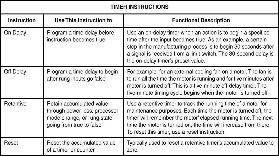
15 Timer Instructions

16 Counters
17 C5, Counter File (1 of 2) The counter file stores only counter elements. An element is a word or group of words that work together as a unit. A counter is made of three pieces or words. Preset value Accumulated value Status bits
18 C5, Counter File (2 of 2) The preset value and accumulated value are 16-bit signed integers. Status bits are single bits that make up one 16-bit word. These three words work together as a unit.
19 One Counter Element Is Made of Three 16-bit Words
20 Counter Addressing Sample counter element address C5:2 C5 = timer file 5 :2 = counter element #2 (0-255 timer elements per file)
21 Sub-element A sub-element is part of an element addressable as a unit. The preset value and accumulated value are sub-elements of a counter. C5:0.PRE C5:0.ACC
22 Counter Status Bits (1 of 2) Counters have five status bits. Done bit (DN) is true when the accumulated value and preset are equal. Count up enable bit (CU) is true when the up counter is true or enabled. Count down enable bit (CD) is true when the count down counter is enabled or true.
23 Counter Status Bits (2 of 2) The overflow bit (OV) is true when the up counter has overflowed above The underflow bit (UN) is true when the down counter has underflowed below The update accumulator bit (UA) is a highspeed counter status bit for fixed SLC 500 PLCs.
24 Counter Status Bit Addressing Status bit addresses for counter file 5, counter element 0 (C5:0) are listed below: C5:0/DN is the address for the done bit. C5:0/CU is the address for the count up enable bit. C5:0/CD is the address for the count down enable bit. C5:0/OV is the address for the count up overflow bit. C5:0/UN is the address for the count down underflow bit.

25

26 Counters
27 SLC 500 Count Up Counter
28 SLC 500 Count Down Counter
29 SLC 500 Count Down Counter Instruction
30 Reset Instruction to Reset Counter C20:7
31 Using the Clear Instruction to Clear C5:0.ACC and C5:1.ACC
32 Comparison Instructions Input instructions that test the relationship between two values, source A and source B Source A is an address. Source B can be an address or a constant value.
33 Equal Instruction (EQU) Test when two values are equal. Instruction is true when source A is equal to source B.
34 An Equal Instruction Controlling OTE Instruction
35 Not Equal Instruction (NEQ) Test when two values for inequality. Use this instruction to determine if two specified sources are not equal. Instruction is true when source A is not equal to source B.
36 Not Equal Instruction
37 Less Than Instruction (LES) (1 of 2) Test when one value is less than another. Instruction is true when the data stored in source A is less than either the data stored in the address specified as source B or a constant entered in source B.
38 The Less Than Instruction (2 of 2)
39 Less Than or Equal (LEQ) Determine if one source of data is less than or equal to another. Instruction is true when the data stored in source A is less than or equal to either the data stored in the address specified as source B or a constant entered in source B.
40 Less Than or Equal Instruction
41 Greater Than Instruction (GEQ) Determine if one source of data is greater than another. Instruction is true when the data stored in source A is greater than either the data stored in the address specified as source B or a constant entered in source B.
42 The Greater Than Instruction
43 Greater Than or Equal (GEQ) Determine if one source of data is greater than or equal to another. Instruction is true when the data stored in source A is greater than or equal to either the data stored in the address specified as source B or a constant entered in source B.
44 Greater Than or Equal Instruction
45 Data-handling Instructions Used when data needs to be moved or copied from one data file source to another When data needs to be converted to a different radix
46 Move Instruction (MOV) (1 of 2) This is an output instruction that moves a copy of one data file element to a specified destination. The source can be an address or constant. When instruction is true, a copy of the source data will be moved to the specified destination address.
47 Move Instruction (2 of 2)
48 Masked Move Instruction (MVM) (1 of 2) This is an output instruction that moves a copy of one data file element through a mask to a specified destination. When true, a copy of the data specified in the source is moved through a hexadecimal mask to the specified destination.
49 Masked Move Instruction (2 of 2)
50 Hexadecimal Masking Source data is passed through the mask bit by bit. Mask bit in same position as source bit determines if data is to pass or not. To pass data through mask, set appropriate mask bit. To mask data from passing, reset the appropriate mask bit.
51 Source Data Moved through the Mask to the Destination
52 Mask Rules Mask is either a hexadecimal value or the address where the mask will be found. Data is evaluated on a bit by bit basis. Mask 1 bits allow data to pass. Mask 0 bits hold data from passing. Destination bits that correspond to zeros in the mask are not changed.
53 FRD Instruction Converting BCD Input Data to Integer
54 TOD Instruction Converting Integer Output Data to BCD
55 Copy File Instruction (COP) Output instruction that copies a user-defined group of 16-bit data file words Must copy consecutive dat file elements Copy up to 128 one-word elements Source and destination can be different file types
56 Copy File Programming Parameters (1 of 2) Source is the address of the file to be copied. The # symbol in front of the source address specifies this address as the beginning of a user-defined source file. Destination is the starting address from which the number of source elements specified in the length parameter will be copied. # specifies copying a user-defined file.
57 Copy File Programming Parameters (2 of 2) Length parameter is the number of consecutive elements to be copied. Because different file types can be copied, the destination file type and length specify how many elements will be transferred.
58 Example of Copy File Instruction Operation
59 Ladder Containing Copy Instruction
60 AND Instruction The AND instruction performs a logical AND operation on two 16-bit words.
61 OR Instruction on a Ladder Rung
62 Exclusive-OR Instruction on a Ladder Rung
63 Not Logic As an Output Instruction on a PLC Ladder Rung
64 The Limit Test Instruction Testing for Values between 0 and 1750
65 The Limit Test Instruction Testing for Values outside the Range of 0 to 100
66 Data Flow from a VFD into the PLC
67 Scale with Parameters
68
69
70
GP-PRO/PBIII for Windows Device/PLC CONNECTION MANUAL. Control Logix 5000 Series (Ethernet)
") GP-PRO/PBIII for Windows Device/PLC CONNECTION MANUAL ADDITIONAL MANUAL Rockwell (Allen-Bradley) Control Logix 5000 Series (Ethernet) Reading the GP-PRO/PBIII Device/PLC Connection Manual This document
GP-PRO/PBIII for Windows Device/PLC CONNECTION MANUAL ADDITIONAL MANUAL Rockwell (Allen-Bradley) Control Logix 5000 Series (Ethernet) Reading the GP-PRO/PBIII Device/PLC Connection Manual This document
GP-PRO/PBIII for Windows Device/PLC CONNECTION MANUAL. SLC500 Series (Ethernet)
") GP-PRO/PBIII for Windows Device/PLC CONNECTION MANUAL ADDITIONAL MANUAL Rockwell (Allen-Bradley) SLC500 Series (Ethernet) Reading the GP-PRO/PBIII Device/PLC Connection Manual This document is designed
GP-PRO/PBIII for Windows Device/PLC CONNECTION MANUAL ADDITIONAL MANUAL Rockwell (Allen-Bradley) SLC500 Series (Ethernet) Reading the GP-PRO/PBIII Device/PLC Connection Manual This document is designed
PLC-5 LADDER LOGISTICS - Rockwell Software Inc. Revision v8.07
 +----------------------------------------------------------+ PLC-5 LADDER LOGISTICS - Rockwell Software Inc. Revision v8.07 Project Name:AI5 Time/Date:15:27 10/23/08 +----------------------------------------------------------+
Device/PLC Connection Manuals
 Device/PLC Connection Manuals About the Device/PLC Connection Manuals Prior to reading these manuals and setting up your device, be sure to read the "Important: Prior to reading the Device/PLC Connection
Mapping to RSLogix500 Based Processors in Crimson
 Mapping to RSLogix500 Based Processors in Introduction The majority of the mappings will match between and, this document is intended to cover the mappings that differ between the two software platforms.
Device/PLC Connection Manuals
 Device/PLC Connection Manuals About the Device/PLC Connection Manuals Prior to reading these manuals and setting up your device, be sure to read the "Important: Prior to reading the Device/PLC Connection
Mechatronics Programmable Logic Controller Basic Programming Courseware Sample
 Mechatronics Programmable Logic Controller Basic Programming Courseware Sample 52281-F0 Order no.: 52281-10 First Edition Revision level: 08/2015 By the staff of Festo Didactic Festo Didactic Ltée/Ltd,
MicroLogix 1100 RSLogix 500 LAB#2
 MicroLogix 1100 RSLogix 500 LAB#2 Timing, Counting & Comparing 1 What we are going to do: I:0/0 O:0/0 ] [ ( ) I:0/1 ]/[ ] [ ]/[ ( ) T4:0/DN ] [ O:0/1 I:0/2 O:0/1 ] [ O:0/1 ] [ I:0/3 C5:0 ] [ ( RES ) L
Courseware Sample F0
 Electric Power / Controls Courseware Sample 3617-F ELECTRIC POWER / CONTROLS COURSEWARE SAMPLE by the Staff of Lab-Volt (Quebec) Ltd Copyright 24 Lab-Volt Ltd All rights reserved. No part of this publication
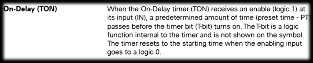
To program and test PLC ladder programs that use timer instructions. Timer Instructions of the Trainer PLC. the timer-on-delay (TON) instruction;
 instruction;") Exercise 5 Timer Instructions EXERCISE OBJECTIVE To program and test PLC ladder programs that use timer instructions. DISCUSSION Introduction PLC timer instructions are output instructions that can be
Exercise 5 Timer Instructions EXERCISE OBJECTIVE To program and test PLC ladder programs that use timer instructions. DISCUSSION Introduction PLC timer instructions are output instructions that can be
MECH 1500 Quiz 4 Review
 Class: Date: MECH 1500 Quiz 4 Review True/False Indicate whether the statement is true or false. 1. For the timer relay contact shown, when the relay coil is energized, there is a time delay before the
An-Najah National University Faculty of Engineering Electrical Engineering Department Programmable Logic Controller. Chapter 11 Math instruction
 Chapter 11 Math instruction Math instructions, like data manipulation instructions, enable the programmable controller to take on more of the qualities of a conventional computer. The PLC s math functions
Allen-Bradley SLC5 Driver Configuration Manual
 Allen-Bradley SLC5 Driver Configuration Manual Version 7.0 rev 0a Advantech Corp., Ltd. page 1 Table of Contents Allen-Bradley SLC5 Driver Configuration Manual 1 1. Configuration 2 1.1... 2 1.2 Module
MicroLogix 1200 Programmable Controllers
 Document Update MicroLogix 1200 Programmable Controllers (Catalog Numbers 1762-L24AWA, -L24BWA, - L24BXB, -L40AWA, -L40BWA and -L40BXB; Series C) Purpose of This Document This Document Update revises the
Table of Contents. Chapter Description Page. 1. PLC Fundamentals Ladder Logic
 vii Table of Contents Chapter Description Page 1. PLC Fundamentals... 1 1 1.1 Ladder Logic... 1 2 1.1.1 Schematic Drawing... 1 3 1.1.2 Hardwired System... 1 4 1.2 PLC System... 1 5 1.3 Major Components...
Device/PLC Connection Manuals
 Device/PLC Connection Manuals About the Device/PLC Connection Manuals Prior to reading these manuals and setting up your device, be sure to read the "Important: Prior to reading the Device/PLC Connection
(Catalog Number 1747 PT1) User Manual. Allen-Bradley Parts
 User Manual. Allen-Bradley Parts") (Catalog Number 1747 PT1) User Manual Allen-Bradley Parts Solid state equipment has operational characteristics differing from those of electromechanical equipment. Safety Guidelines for the Application,
(Catalog Number 1747 PT1) User Manual Allen-Bradley Parts Solid state equipment has operational characteristics differing from those of electromechanical equipment. Safety Guidelines for the Application,
Unit II APPLICATIONS OF PLC
 EI6702-Logic & Distributed Control System Unit II Applications of PLC Unit II APPLICATIONS OF PLC 2.1 PROGRAM CONTROL INSTRUCTIONS Program control instructions are used to alter the program scan from its
Converting PLC-5 or SLC 500 Logic to Logix-Based Logic
 Converting PLC-5 or Logic to Logix-Based Logic 1756 ControlLogix Controllers 1769 CompactLogix Controllers 1789 SoftLogix Controllers 1794 FlexLogix Controllers PowerFlex 700S DriveLogix Controllers Reference
MicroLogix 1200 and MicroLogix 1500 Programmable Controllers
 Document Update MicroLogix 1200 and MicroLogix 1500 Programmable Controllers (Bulletins 1762 and 1764) Purpose of This Document This Document Update revises the following publication. Keep this Document
RSLogix500 Project Report
 RSLogix500 Project Report Processor Information Processor Type: MicroLogix 1200 Series C (1 or 2 Comm Ports) Processor Name: UNTITLED Total Memory Used: 88 Instruction Words Used - 37 Data Table Words
Generic 3 Station Vacuum Loader
 Generic 3 Station Vacuum oader Processor Information Processor Type: Bul.1761 Microogix 1000 Processor Name: OADER Total Memory sed: * Total Memory eft: * Program Files: 17 Data Files: 8 Program ID: 0
Table of Contents. Chapter Description Page. 1. PLC Fundamentals Ladder Logic
 Page v Table of Contents Chapter Description Page 1. PLC Fundamentals... 1 1 1.1 Ladder Logic... 1 1 1.1.1 Hardwired System... 1 3 1.1.2 PLC System... 1 4 1.2 Major Components... 1 5 1.2.1 Chassis... 1
Programmable Logic Controllers. Second Edition
 Programmable Logic Controllers James A. Rehg Second Edition Glenn J. Sartori Pearson Education Limited Edinburgh Gate Harlow Essex CM20 2JE England and Associated Companies throughout the world Visit us
DF1 Driver. Rockwell Automation, Inc.
 Rockwell Automation, Inc. DF1 Driver 1 System Configuration... 3 2 Selection of External Device... 6 3 Example of Communication Setting... 7 4 Setup Items...23 5 Cable Diagram... 29 6 Supported Device...
PLC Counter Instructions
 Chapter 9 Quiz PLC Counter Instructions Name Date Instructor Instructions: Write your answers on the lines provided. 1. You must use the instruction to reset a count up instruction. 2. The content of an
SLC Examples Application Manual
 SLC Example Ladder Manual 3150-MCM Example Ladder Logic Revision 2.1 February 23, 2000 Quick Start Implementation Guide... 2 SLC Ladder Logic Examples... 3 Testing Tools and Suggestions... 3 Slave Mode
BASIC PLC PROGRAMMING
 Q. What are ladder diagrams and sequence listing? Ladder diagram: Ladder diagrams are the most commonly used diagrams for nonelectronic control circuits. They are sometimes called elementary diagrams or
Allen Bradley PLC-5. EthernetSupport.com. Customized Automation Training. Maintenance and Troubleshooting. PLC Maintenance and Troubleshooting 1
 Allen Bradley PLC-5 Maintenance and Troubleshooting EthernetSupport.com Customized Automation Training PLC Maintenance and Troubleshooting 1 PLC Maintenance and Troubleshooting 2 Copyright (c) 1999 Ricky
TC40 - Pre-Instructional Survey
 TC40 - Pre-Instructional Survey 1. Identify the instruction symbol shown. A. Normally Open B. Examine Input Open C. Examine Input Closed D. Normally Closed 2. Identify the instruction symbol shown. A.
Sequencer Instructions
 Enter 1 s at the proper bit locations of data file B10 so that it contains the same data as Table 7-2 below. When you have finished, close data file B10. Note: To enter a 1 at a bit location, double-click
Rockwell Automation Allen-Bradley EtherNet/IP Driver
 Rockwell Automation Rockwell Automation Allen-Bradley EtherNet/IP Driver 1 System Structure 2 Supported Device Addresses 3 Consecutive Device Addresses 4 I/O Manager Configuration 5 Protocol Configuration
PLC Programming D R. T A R E K A. T U T U N J I
 PLC Programming D R. T A R E K A. T U T U N J I PLC Programming As PLCs developed and expanded, programming languages have developed with them. The three types of programming languages used in PLCs are:
PASSWORD (Creating a program in the PLC and touchscreen)
") PASSWORD (Creating a program in the PLC and touchscreen) This sample program provides a step by step process on how to create a password to protect a screen. It involves creating a program in the touchscreen
PASSWORD (Creating a program in the PLC and touchscreen) This sample program provides a step by step process on how to create a password to protect a screen. It involves creating a program in the touchscreen
1 of 8. I. (13pts) TRUE OR FALSE
 TRUE OR FALSE") Sample PLC Final Exam Name (1pt): By signing I agree to abide by the UWA policies governing academic integrity. I. (13pts) TRUE OR FALSE 1. The user memory segment stores information needed to execute
Sample PLC Final Exam Name (1pt): By signing I agree to abide by the UWA policies governing academic integrity. I. (13pts) TRUE OR FALSE 1. The user memory segment stores information needed to execute
(Catalog Number 1747-SN) Product Data
 Product Data") (Catalog Number 1747-SN) Product Data At communication rates up to 230.4K baud, the Remote I/O Scanner provides connectivity of your SLC 500 processor to Allen-Bradley operator interface devices, drives,
(Catalog Number 1747-SN) Product Data At communication rates up to 230.4K baud, the Remote I/O Scanner provides connectivity of your SLC 500 processor to Allen-Bradley operator interface devices, drives,
PLC Workshop Suite for CTI 2500 Series Product Bulletin: Enhanced Instructions
 FasTrak SoftWorks, Inc. worked with partner Control Technology, Inc. to create enhanced instructions for the CTI 2500 Series TM processors. These instructions allow robust programming through the PLC WorkShop
Allen-Bradley Replacement
 Preface...? Who Should Use this Manual...? Purpose of this Manual...? Common T echniques Used in this Manual...? Setting Up Your Equipment... Hardware Requirements... Controller Styles... Setting Up a
Throughout this manual we use notes to make you aware of safety considerations:
 Because of the variety of uses for the products described in this publication, those responsible for the application and use of this control equipment must satisfy themselves that all necessary steps have
Multi-hop Messaging using SLC 5/05 Processor via Ethernet
 Release Note Multi-hop Messaging using SLC 5/05 Processor via Ethernet Introduction Read this document before using SLC 5/05 (1747-OS50?, FRN?) processors. Keep this document with your SLC 500 and Micrologix
Ch. 5 Control Task Basics 1
 Chapter 5 Control Task Basics Modeling the Control Task Most verbal descriptions of a technical task are not effective in their scope and are unreliable and not clear-cut. A technical sketch, on the other
Wonderware Allen-Bradley Ethernet Direct I/O Server
 Wonderware Allen-Bradley Ethernet Direct I/O Server User s Guide Revision I June 2001 Wonderware Corporation All rights reserved. No part of this documentation shall be reproduced, stored in a retrieval
Timers. Time Value: Bits 0 through 9 of the timer word contain the time value in binary code.
 Timers Memory Area: Timers have an area reserved for them in the memory of your CPU. This memory area reserves one 16-bit word for each timer address. When you program in FBD, 256 timers are supported.
Logix5000 Controllers Produced and Consumed Tags
 Logix5 Controllers Produced and Consumed Tags Catalog Numbers 1756 ControlLogix, 1756 GuardLogix, 1768 Compact GuardLogix, 1769 CompactLogix, 1789 SoftLogix, PowerFlex with DriveLogix Programming Manual
PREVIEW COPY. Table of Contents. Introduction to Programmable Logic Controllers...3. Number Systems and Logic...25
 Table of Contents Lesson One Lesson Two Introduction to Programmable Logic Controllers...3 Number Systems and Logic...25 Lesson Three Programming the System...43 Lesson Four Input/Output Devices and Modules...63
Logix5000 Controllers Produced and Consumed Tags
 Programming Manual Logix5 Controllers Produced and Consumed Tags Catalog Numbers 1756 ControlLogix, 1756 GuardLogix, 1768 Compact GuardLogix, 1769 CompactLogix, 1789 SoftLogix, PowerFlex with DriveLogix
Automation Products for the New Millennium
 Automation Products for the New Millennium 21640 N. 19 th Ave Ste C6 Phoenix AZ 85027 USA www.vsi-az.com 623-434-6621 1. OVERVIEW... 3 2. SOFTWARE REQUIREMENTS AND INSTALLATION... 3 3. WORKBENCH COMPONENTS...
Configuring EtherMeter MicroLogix (1100/1400) Communications Using EtherNet/IP.
 Communications Using EtherNet/IP.") Application Note 002 Version 004 17 Dec 2015 Configuring EtherMeter MicroLogix (1100/1400) Communications Using EtherNet/IP. (Note: This document also applies to EtherMeter-SLC/505 Communications.) The
Application Note 002 Version 004 17 Dec 2015 Configuring EtherMeter MicroLogix (1100/1400) Communications Using EtherNet/IP. (Note: This document also applies to EtherMeter-SLC/505 Communications.) The
CTEET003_Programmable Logic Controls CTAG Rubric EET. Some applied skills present
 depends strongly on courses taught primarily at the some applied skills and applied skills strongly levels. 1. Recall the history of control systems and PLCs.* Describe what electrical control is. Create
Allen-Bradley Ethernet Driver PTC Inc. All Rights Reserved.
 2018 PTC Inc. All Rights Reserved. 2 Table of Contents 1 Table of Contents 2 4 Overview 5 Setup 6 Channel Properties General 6 Channel Properties Ethernet Communications 7 Channel Properties Write Optimizations
ELECTRICAL ENGINEERING TECHNOLOGY Introduction to RSLogix 5000 and the Compact Logix PLC
 KENNESAW STATE UNIVERSITY ECET 4530 ELECTRICAL ENGINEERING TECHNOLOGY Introduction to RSLogix 5000 and the Compact Logix PLC Introduction: In this exercise you will setup, configure, program and operate
FA-M3 Ethernet (TCP) Driver
 Driver") Yokogawa Electric FA-M3 Ethernet (TCP) Driver 1 System Structure 2 Supported Device Addresses 3 Consecutive Device Addresses 4 Environment Setup 5 I/O Manager Configuration 6 Protocol Configuration 7 Device
Yokogawa Electric FA-M3 Ethernet (TCP) Driver 1 System Structure 2 Supported Device Addresses 3 Consecutive Device Addresses 4 Environment Setup 5 I/O Manager Configuration 6 Protocol Configuration 7 Device
Table of Contents
 Table of Contents Table of Contents Table of Contents The bulletin 1772-PLC-2/20 programmable controller is a rugged, solid state programmable controller that consists of the PLC-2/20 Processor (cat. no.
Allen Bradley SLC-500
 Allen Bradley SLC-500 Maintenance and Troubleshooting EthernetSupport.com Customized Automation Training SLC500 Maintenance and Troubleshooting 1 Copyright (c) 1999 Ricky Bryce. Permission is granted to
Logix5000 Data Access
 Reference Manual Logix5000 Data Access Purpose This documents describes how to access data from a Logix5000 controller using the following methods: CIP Services (inherent Logix5000 mode of communications)
Program Control Instructions
 Program Control Instructions Industrial Controls University of Akron Overview Master Control Reset and Master Control Relay Jump and Subroutine Instructions Immediate Input and Output Forcing Input and
Chapter 6 Basic Function Instruction
 Chapter 6 Basic Function Instruction T 6-2 C 6-5 SET 6-8 RST 6- : MC 6-2 : MCE 6-4 2: SKP 6-5 3: SKPE 6-7 4: DIFU 6-8 5: DIFD 6-9 6: BSHF 6-2 7: UDCTR 6-2 8: MOV 6-23 9: MOV/ 6-24 : TOGG 6-25 : (+) 6-26
464E PLC Trainer, Extended
 464E PLC Trainer, Extended GENERAL DESCRIPTION A multi-use training platform allowing for instruction related to the programming and use of industrial PLCs. The basic device is provided without a PLC,
WebAccess Driver Configuration Manual
 WebAccess AB MicroLogix 1400 ABDrv.DLL Driver date: 2015/3/30 English Version 1.1 Revision History Date Version Author Reviewer Description 2018-10-29 1.0 Alger.Tan ChiRen.Wei Initial Release 2018-11-2
MGM'S JAWAHARLAL NEHRU ENGINEERING COLLEGE AURANGABAD
 MGM'S JAWAHARLAL NEHRU ENGINEERING COLLEGE AURANGABAD LABORATORY MANUAL PROGRAMMABLE LOGIC CONTROL & DISTRIBUTED CONTROL SYSTEM FOR THIRD YEAR ICE STUDENTS Preface It is my great pleasure to present theoretical
Industrial Automation de Processos Industriais)
") Industrial Automation (Automação de Processos Industriais) PLC Programming languages Ladder Diagram http://users.isr.ist.utl.pt/~jag/courses/api1516/api1516.html Slides 2010/2011 Prof. Paulo Jorge Oliveira
Industrial Automation (Automação de Processos Industriais) PLC Programming languages Ladder Diagram http://users.isr.ist.utl.pt/~jag/courses/api1516/api1516.html Slides 2010/2011 Prof. Paulo Jorge Oliveira
WRC Modbus to DeviceNet Gateway for GPD 506/P5
 Introduction This document describes the recommended method to configure and connect Western Reserve Controls (WRC) Modbus to DeviceNet gateway for use with the GPD 506/P5. There currently are three types
Chapter 3: Number Systems and Codes. Textbook: Petruzella, Frank D., Programmable Logic Controllers. McGraw Hill Companies Inc.
 Chapter 3: Number Systems and Codes Textbook: Petruzella, Frank D., Programmable Logic Controllers. McGraw Hill Companies Inc., 5 th edition Decimal System The radix or base of a number system determines
Version 2.1. Publication ERSC-1200
 Version 2.1 April 2016 Publication ERSC-1200 Important User Information 3 Important User Information ConveyLinx ERSC modules contain ESD (Electrostatic Discharge) sensitive parts and components. Static
Programmable Logic Controllers (PLCs) An Overview
 An Overview") Programmable Logic Controllers (PLCs) An Overview Chapter Objectives Photo courtesy Rockwell Automation, Inc. After completing this chapter, you will be able to:. Define what a programmable logic controller
Programmable Logic Controllers (PLCs) An Overview Chapter Objectives Photo courtesy Rockwell Automation, Inc. After completing this chapter, you will be able to:. Define what a programmable logic controller
Assembly Language Programming of 8085
 Assembly Language Programming of 8085 1. Introduction A microprocessor executes instructions given by the user Instructions should be in a language known to the microprocessor Microprocessor understands
Instructor Guide. 401: Programmable Logic Controllers Module 2: Advanced Programming Systems
 Instructor Guide 401: Programmable Logic Controllers Module 2: d Programming Systems Elevator Escalator Programmable Logic Controllers Table of Contents Overview....... SLC500 Series Processor Operation..
3100/ N2 Johnson Controls N2 Slave Interface Module Revision 1.01 USER MANUAL. January 1996 Updated April, 1998
 3100/3150 - N2 Johnson Controls N2 Slave Interface Module Revision 1.01 USER MANUAL January 1996 Updated April, 1998 ProSoft Technology, Inc. 1675 Chester Ave. Fourth Floor Bakersfield, CA 93301 prosoft@prosoft-technology.com
Special Memory (SM) Bits
 Bits") C Special memory bits provide a variety of status and control functions, and also serve as a means of communicating information between the CPU and your program. Special memory bits can be used as bits,
C Special memory bits provide a variety of status and control functions, and also serve as a means of communicating information between the CPU and your program. Special memory bits can be used as bits,
Introduction to Programmable Logic Controllers (PLC's)
") Introduction to Programmable Logic Controllers (PLC's) Industrial Control Systems Fall 2006 Lecture Introduction to PLC's MME 486 Fall 2006 1 of 47 The Need for PLCs Hardwired panels were very time consuming
Introduction to Programmable Logic Controllers (PLC's) Industrial Control Systems Fall 2006 Lecture Introduction to PLC's MME 486 Fall 2006 1 of 47 The Need for PLCs Hardwired panels were very time consuming
PLC AUTOMATION SYSTEM LABORATORY. Manual
 MRS AVN COLLEGE POLYTECHNIC VISAKHAPATNAM DEPARTMENT OF ELECTRICAL ELECTRONICS ENGINEERING PLC AUTOMATION SYSTEM LABORATORY Manual PLC Automation System Laboratory Lab 1 : Getting familiar with Step 7-
28 Using Logic Functions
 28 Using Logic Functions This chapter explains what you can do using the GP-Pro EX Logic Feature. First, read "28.1 Settings Menu" (page 28-2), and then go to the corresponding page for further instructions.
Allen-Bradley Data Highway Plus Driver PTC Inc. All Rights Reserved.
 2018 PTC Inc. All Rights Reserved. 2 Table of Contents 1 Table of Contents 2 5 Overview 6 Setup 7 Requirements and Dependencies 7 Channel Setup 8 Channel Properties General 8 Channel Properties Write Optimizations
Using Message Instructions to Communicate with an Ethernet IP Nexus Unit
 Communicating to an AMCI Ethernet IP Nexus unit is typically accomplished by using a scanner module in the PLC rack. However, it is also possible to communicate with these units directly using instructions
Allen-Bradley DH+ Driver Help Kepware Technologies
 Allen-Bradley DH+ Driver Help 2011 Kepware Technologies 2 Table of Contents Table of Contents 2 5 Overview 5 Channel Setup 6 Channel Properties 6 Channel Setup for the Allen Bradley- 1784 KT Card 7 Channel
3100/3150-ROC Fisher ROC Communications Revision 1.2 March 8, 2001
 3100/3150-ROC Fisher ROC Communications Revision 1.2 March 8, 2001 USER MANUAL ProSoft Technology, Inc. 9801 Camino Media, Suite 105 Bakersfield, CA 93311 (661) 664-7208 (661) 664-7233 (fax) E-mail address:
Automating with STEP 7 in STL
 Automating with STEP 7 in STL SIMATICS 7-300/400 Programmable Controllers by Hans Berger Publicis MCD Verlag Contents Introduction 16 1 SIMATIC S 7-300/400 Programmable Controller 17 1.1 Structure of the
Table of Contents
 Table of Contents Table of Contents Analog Input Module (12-Bit) Assembly cat. no. 1771-IF Series B and Analog Input Expander (12-Bit) cat. no. 1771-E1, -E2, -E3 are plug-in modules that interface analog
Automatic Analysis of Relay Ladder Logic Programs
 Automatic Analysis of Relay Ladder Logic Programs Zhendong Su Report No. UCB/CSD-97-969 September 1997 Computer Science Division (EECS) University of California Berkeley, California 94720 Automatic Analysis
Communications Protocol
 SLC lm Programmable Controller Contents SLC Page 1 Format of Transmission 1 Map Specific Commands 4 The Memory 8 User Address to Controller Address Table 10 Addresses Program User Connector Pin Configuration
Appendix B. DL105/DL205/DL350/DL405 Application Examples. In This Appendix... DL105/DL205/DL350/DL405 Application Example
 DL105/DL205/DL350/DL405 Application Examples In This Appendix.... DL105/DL205/DL350/DL405 Application Example B 2 DL105/DL205/DL350/DL405 Application Example Understanding the Example Programs In this
Assembly Language Programming of 8085
 Assembly Language Programming of 8085 Topics 1. Introduction 2. Programming model of 8085 3. Instruction set of 8085 4. Example Programs 5. Addressing modes of 8085 6. Instruction & Data Formats of 8085
Throughout this manual we use notes to make you aware of safety considerations:
 Because of the variety of uses for the products described in this publication, those responsible for the application and use of this control equipment must satisfy themselves that all necessary steps have
Getting Results Guide. Doc ID EMULAT-GR002A-EN-P
 Getting Results Guide Doc ID EMULAT-GR002A-EN-P Contacting Technical Support Telephone 1-440-646-7800 Rockwell Software Technical Support Fax 1-440-646-7801 World Wide Web www.software.rockwell.com Copyright
EE 109L Review. Name: Solutions
 EE 9L Review Name: Solutions Closed Book / Score:. Short Answer (6 pts.) a. Storing temporary values in (memory / registers) is preferred due to the (increased / decreased) access time. b. True / False:
that system. weighted value associated with it. numbers. a number. the absence of a signal. MECH 1500 Quiz 2 Review Name: Class: Date:
 Name: Class: Date: MECH 1500 Quiz 2 Review True/False Indicate whether the statement is true or false. 1. The decimal system uses the number 9 as its base. 2. All digital computing devices perform operations
Communications. Introduction
 Communications Introduction The communications manual is part of the documentation set for QUICKDESIGNER software. The process of designing panels, loading the panels into a display device and connecting
Chapter. Getting Started, Basics. and Examples. In This Chapter...
 Getting Started, Basics and Examples Chapter 2 In This Chapter... Overview... 2-2 Basic Motion Functions, Summary of Examples... 2-2 Detailed Example: Configure and Test a Quadrature Input... 2-7 Detailed
Motors I Automation I Energy I Transmission & Distribution I Coatings. SoftPLC CFW100. User Manual
 Motors I Automation I Energy I Transmission & Distribution I Coatings SoftPLC CFW User Manual SoftPLC User Manual Series: CFW Language: English Document Number: 2965849 / 2 Publication Date: /24 Contents
4. Draw the general ladder rungs to represent a latch circuit. (N/D 2009)
") (Other possible questions) 1. What is meant by PLC? (N/D 2012) A programmable logic controller is a microprocessor based controller that uses a programmable memory to store instructions and to implement
(Other possible questions) 1. What is meant by PLC? (N/D 2012) A programmable logic controller is a microprocessor based controller that uses a programmable memory to store instructions and to implement
Motors I Automation I Energy I Transmission & Distribution I Coatings. SoftPLC CFW500. User s Manual
 Motors I Automation I Energy I Transmission & Distribution I Coatings SoftPLC CFW5 User s Manual SoftPLC Manual Series: CFW5 Language: English Document Number: 2299985 / Publication Date: 6/25 Summary
2.1 ES2/EX2 Memory Map
 DVP-ES2/EX2/SS2/SA2/SX2 Operation Manual - Programming 2.1 ES2/EX2 Memory Map Specifications Control Method I/O Processing Method Execution Speed Program language Program Capacity Stored program, cyclic
EXPERIMENT NO.1. A Microcontroller is a complete computer system built on a single chip.
 EXPERIMENT NO.1 AIM: Study of 8051 Microcontroller TOOLS: 8051 kit THEORY: Salient Features of 8051 A Microcontroller is a complete computer system built on a single chip. It contains all components like
LAB 10 INTRODUCTION TO LADDER LOGIC PROGRAMMING. 2 Lab Equipment 2.1. CLICK Series Micro Programmable Logic Controller (PLC)
") LAB 10 INTRODUCTION TO LADDER LOGIC PROGRAMMING 1 Lab Objective In this lab you will be introduced to programmable logic controllers and the use of relay ladder logic. 2 Lab Equipment 2.1. CLICK Series
LAB 10 INTRODUCTION TO LADDER LOGIC PROGRAMMING 1 Lab Objective In this lab you will be introduced to programmable logic controllers and the use of relay ladder logic. 2 Lab Equipment 2.1. CLICK Series
SLC 5/03, SLC 5/04 and SLC 5/05 Operating Systems
 Document Update SLC 5/03, SLC 5/04 and SLC 5/05 Operating Systems (Catalog Numbers 1747-L531, 1747-L532, 1747-L541, 1747-L542, 1747-L543, 1747-L551, 1747-L552 and 1747-L553) Introduction Read this document
Artisan Technology Group is your source for quality new and certified-used/pre-owned equipment
 Artisan Technology Group is your source for quality new and certified-used/pre-owned equipment FAST SHIPPING AND DELIVERY TENS OF THOUSANDS OF IN-STOCK ITEMS EQUIPMENT DEMOS HUNDREDS OF MANUFACTURERS SUPPORTED
TECHNICAL BULLETIN. Edwards Signaling Products 90 Fieldstone Court Cheshire, CT (203) FAX (203)
 FAX (203)") Technical Bulletin # 970519 Date: June 1, 1999 Product: Message Centers Product Category: Allen-Bradley SLC-5/03 Connectivity Diagram 1 Edwards Signaling Products 90 Fieldstone Court Cheshire, CT 06410
Technical Bulletin # 970519 Date: June 1, 1999 Product: Message Centers Product Category: Allen-Bradley SLC-5/03 Connectivity Diagram 1 Edwards Signaling Products 90 Fieldstone Court Cheshire, CT 06410
Mark II Aiken Relay Calculator
 Introduction to Embedded Microcomputer Systems Lecture 6.1 Mark II Aiken Relay Calculator 2.12. Tutorial 2. Arithmetic and logical operations format descriptions examples h 8-bit unsigned hexadecimal $00
SoftLogix 5 Controller
 Release Notes SoftLogix 5 Controller (Catalog Number 1789-SL5, -SL51, -SL52) These release notes correspond to version 2.2.0 of the SoftLogix 5 Controller. For Information On: See Page: HTML Help 1 Corrected
Logix5000 Controllers Major, Minor, and I/O Faults
 Logix5000 Controllers Major, Minor, and I/O Faults Catalog Numbers 1756 ControlLogix, 1756 GuardLogix, 1768 Compact GuardLogix, 1768 CompactLogix, 1769 CompactLogix, 1789 SoftLogix, PowerFlex with DriveLogix