WCT1011A/WCT1013A Automotive MP-A9 V4.0 Run-Time Debugging
|
|
|
- Laura Matthews
- 5 years ago
- Views:
Transcription
1 NXP Semiconductors Document Number: WCT101XAV40RTDUG User's Guide Rev. 4.0, 05/2018 WCT1011A/WCT1013A Automotive MP-A9 V4.0 Run-Time Debugging 1 Introduction NXP provides the FreeMASTER GUI tool for WCT1011A/WCT1013A Automotive Medium Power wireless charging solution. The GUI based on the FreeMASTER tool can be used to fine-tune the parameters in running state. For the operations of setting up the FreeMASTER connection, see the WCT1011A/WCT1013A Automotive MP-A9 V4.0 Wireless Charging Application User s Guide (WCT101XAV40AUG). Contents 1 Introduction Runtime Tuning and Debugging NVM parameters Tuning and debugging Calibration NVM Structure Reference Operation parameters Calibration parameters Revision History Runtime Tuning and Debugging 2.1 NVM parameters This chapter describes the configuration and tuning of the NVM parameters. The NVM parameters are initially stored in the Flash memory and copied from there to the NvmParams structure in RAM. Some parameters of the NvmParams structure are passed to the Wireless Charging Transmitter (WCT) library during initialization. The initialization data for the Flash-memory structure are stored in the EEdata_FlashDefaults.asm file NXP B.V.
2 The WCT GUI based on the FreeMASTER tool can be used to fine-tune the parameters. You can use the same GUI to generate the assembler initialization data for the Flash-based configuration. Alternatively, you can use the WCT GUI to trigger the application and back up the actual RAM content of the data structure to flash. The WCT GUI is prepared for the following application: 15W_MP/example/wct101xa/wct101xA.pmp Section 3 NVM Structure Reference provides detailed information about each configuration parameter. The same reference information is also available directly in the GUI tool where the parameters can be changed at runtime Runtime access to NVM parameters As outlined in the previous sections, the WCT GUI based on FreeMASTER tool can be used to read and modify the parameters at runtime. Calibration parameters of the structure are modified immediately, so FOD, Q-factor detection, and quick removal detection can be evaluated instantly. Other parameters for library and protection are modified by the WCT GUI, but they do not take effect immediately. You need to modify these parameters under debug mode. Then these parameters take effect when exit debug mode. The NVM parameters are split to several tabs in the GUI view: Operation Parameters Calibration To make the fine-tuned configuration values permanent and default for the next application build, the whole structure is exported into assembler syntax of initialization data block. The generated data can be put to the EEdata_FlashDefaults.asm file directly and used as a new default configuration set. In addition to the actual configuration values, the GUI also calculates proper checksum values to make the data block valid. The exported initialization data block is available on the NVMraw tab in the GUI. 2 NXP Semiconductors
 (2)")
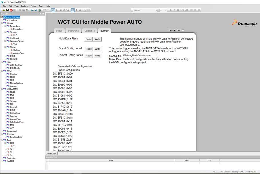
3 WCT GUI (1) WCT GUI (2) NXP Semiconductors 3

4 2.2 Tuning and debugging The library is used together with the FreeMASTER visualization tool to calibrate input values and to observe behavior of the Wireless Charging transmitter. The FreeMASTER tool connects to the target board by using the UART or JTAG communication interface Data visualization The FreeMASTER tool enables visualization of any variables or registers in the application running on the target system. This feature is useful with the Wireless Charging application to observe voltage and currents in real time by using a graphical representation. The FreeMASTER project file that comes in the Library package contains pre-configured scope views with the most frequently used runtime parameters. The graphs and views are easily extended by more parameters or user-defined data Debugging console Data visualization In addition to FreeMASTER visualization, the WCT library provides an option to continuously dump the selected debugging information to the user console over the UART interface. The debug messages are sent to UART whenever an important event occurs, if the appropriate message type is enabled. The console UART port must be different from the UART port used by the FreeMASTER communication. If only one UART port is available, consider the use of an alternative communication interface for the FreeMASTER connection. Next to UART, the FreeMASTER also supports JTAG cable interface. 4 NXP Semiconductors
5 On the current WCT1011A/WCT1013A digital DCDC platform the digital DCDC module occupies one UART port. Only one of the debug consoles and FreeMASTER using SCI can work at a time. If SCI is used for debugging console in MP demo, the settings are as follows: #define DEBUG_CONSOLE_SUPPORTED #define FREEMASTER_SUPPORTED (TRUE) (FASLE) The macros are defined in example-> wct101xa > configure-> appcfg.h. #define QSCI_CONSOLE_INDEX 0 #define QSCI_FREEMASTER_INDEX 1 The macros are defined in example->wct101xa->driver->qsci.h. To use FreeMASTER and debug console at the same time, change the FreeMASTER communication interface to JTAG. The settings are as follows: #define FMSTR_USE_SCI 0 /* To select SCI communication interface */ #define FMSTR_USE_JTAG 1 /* 56F8xxx: use JTAG interface */ The macros are defined in example->wct101xa >configure-> freemaster_cfg.h. #define FREEMASTER_SUPPORTED (TRUE) The macro is defined in example->wct101xa_configure->appcfg.h. 2.3 Calibration The library behavior and its parameters should be calibrated before the library can be successfully used. The calibration procedure consists of four steps: 1. Rail voltage calibration 2. Input current calibration 3. Characterization parameters calibration 4. Normalization parameters calibration All the steps require low power to be disabled and library running in debug mode except normalization parameters calibration. All the calibration steps are used to get accurate power loss for Foreign Object Detection (FOD). Power loss is calculated by the following equation. If P_Loss is bigger than the threshold, there must be a foreign object. P_Loss = T_IN T_Loss R_IN Rail Voltage Calibration and Input Current Calibration are used to get accurate T_IN. Characterization Parameters Calibration is used to estimate T_Loss. Normalization Parameters Calibration is used to get accurate R_IN. NXP Semiconductors 5
6 Calibration NOTE Before starting calibration, read all the values to the NVM data. Click the Read button of Common for all on the Op Params page and Calibration page Rail voltage calibration The process of rail voltage calibration is as follows: Reading NVM value Before the calibration, set LOW_POWER_MODE_ENABLE to FALSE in the example code. Then, the MCU runs at full speed even without charging, and the FreeMASTER GUI can respond quickly when the user performs FOD calibration in debugging mode. Before the TX is powered on, ensure that the RX is removed and load is disconnected. The calibration process of the rail voltage requires library to be running in debug mode, and without RX and load. Use the FreeMASTER GUI to do the calibration, and save the constant to flash. In the Rail Voltage Calibration area, click Reset and Enter. Set a different rail voltage value, click Read, measure rail voltage by multimeter and fill the actual value in the Real V column. Then click Move and Save. 6 NXP Semiconductors
7 Rail voltage calibration Read out the Rail Voltage Calibration Constant on the Calibration page of the FreeMASTER GUI to ensure that it is saved successfully Input current calibration The process of input current calibration is as follows: Read rail voltage calibration constant Power on the wireless charging TX board without load connected. The calibration process of the input current requires the library to be running in debug mode, and without RX on. Click Reset, Enter, and Calibr. NXP Semiconductors 7

8 Input current calibration (1) Add electronic load or resistors between VRAILA and Ground to draw current. Make sure that the load is added after Step 4. Otherwise, the input current cannot be read correctly. Measure the actual current by a multimeter and fill actual value in the Real I column. Then, click Read. Change load current from 50 ma to 2000 ma. Repeat for all the other rows and then click Move and Save. Input current calibration (2) Read out the Input Current Calibration Constant on the Calibration page of the FreeMASTER GUI to ensure that it is saved successfully FOD calibration The process of FOD calibration is as follows: Read input current calibration constant 8 NXP Semiconductors
9 The calibration process of the foreign object detection algorithm requires library running in debug mode and finished calibration of the Rail Voltage and Input Current. The calibration must be done without RX and load. Follow instruction of the Rail Voltage Calibration process. Follow instruction of the Input Current Calibration process. Enter the Coil ID, click Enter and On, and then click Set and Read for each row. Then press Off, Move and Save. FOD calibration Read out the Power Loss Characterization Parameters on the Calibration page of the FreeMASTER GUI to ensure that it is saved successfully. NXP Semiconductors 9

10 Repeat the steps above for the remaining coils FOD normalization Read FOD characterization constants The FOD normalization is to equalize the power loss curve, at which the loss value goes high as the load increasing, and it may be higher than the threshold even no foreign object is present. To resolve the issue, NXP provides the normalization tool through the FreeMASTER GUI to fine-tune the FOD of the performance customer board. The process of FOD normalization is as follows: Make sure that the rail voltage, input current, and FOD calibration are done. Follow the normalization steps on the FreeMASTER GUI as shown in the following figure. Before the test, reset the parameter and exit debug mode. Do the test with a standard calibrated Qi 1.1 RX, like TPR#5. The load range is from 50 ma to 1000 ma. 10 NXP Semiconductors
.")
11 FOD normalization After the steps above on the GUI are finished, read out Power Loss Normalization Parameters on the Calibration page of the FreeMASTER GUI to ensure that it is saved successfully. Read FOD normalization constants NOTE FOD normalization in this section is for baseline RX (5 W). As for Middle Power RX (extension), normalization is not necessary, because the power loss FOD extension method is with online calibration for accuracy. NXP Semiconductors 11
12 2.3.5 Saving new NVM parameters to EEdata After calibration, the NVM parameters are updated; these new parameters need to be used to update the file EEdata_FlashDefaults.asm, so that they could be flashed. Set the QF calibration init check to 0 on the Op Params page, and then click the Write button, as shown in Figure 15 to make sure the auto-calibration for Q factor conversion is done at the first time the TX runs after the flashed image. So, ensure that there is no object on the TX surface at the first time the TX runs after the flashed image. Setting auto calibration check to 0 Before saving the NVM parameters, read all the values to the NVM data as shown in Figure 16. Copy updated NVM data Write the NVM data to EEdata_FlashDefaults.asm. This feature is supported by the FreeMASTER tool v1.4 or later. After you click Write as Figure 17 shows, CodeWarrior prompts that the EEdata_FlashDefaults.asm file has been replaced. Click Yes and rebuild the project for next flashing. 12 NXP Semiconductors
 This parameter defines the coil frequency to be used during Digital Ping operations.")
 This parameter defines the amount of time the Ping frequency should be applied while waiting for")
13 Write NVM data 3 NVM Structure Reference 3.1 Operation parameters Replace EEdata_FlashDefaults.asm file Ping Frequency (Hz) This parameter defines the coil frequency to be used during Digital Ping operations. Default Value: Min Value: Max Value: Member: NvmParams.OpParams.OpStateParams.dwPingFrequency Ping Pulse Duration (ms) This parameter defines the amount of time the Ping frequency should be applied while waiting for device detection. Default Value: 65 Member: NvmParams.OpParams.OpStateParams.wPingPulseDurationTimeMs NXP Semiconductors 13
14 Ping Interval (ms) This parameter defines the amount of time between attempts to Ping the secondary for device detection. Default Value: 400 Member: NvmParams.OpParams.OpStateParams.wPingIntervalMs Coil Current Threshold (% change) This parameter defines the threshold above, which an Analog Ping may have detected a changed in device presence. Default Value: 5 Member: NvmParams.OpParams.OpStateParams.wAnalogPingCoilCurrentThreshold Digital Ping Retry Interval (seconds) This parameter defines the interval at which a digital ping is forced. Default Value: 5 Max Value: 65 Member: NvmParams.OpParams.OpStateParams.byDigitalPingRetryIntervalSeconds Over Coil Current Threshold (ma) This parameter defines the maximum allowable current on the coil (in ma). If coil current exceed this threshold, power transfer is aborted. Default Value: 6500 Member: NvmParams.OpParams.OpStateParams.wOverCoilCurrentThreshold Over Rail Voltage Threshold (mv) This parameter defines the maximum allowable rail voltage (in mv). If rail voltage exceed this threshold, the operational state machine will shut down. Default Value: NXP Semiconductors
15 Member: NvmParams.OpParams.OpStateParams.wOverRailVoltageThreshold Over Input Voltage Threshold (mv) This parameter defines the maximum allowable input voltage (in mv). If the input voltage exceed this threshold, the operational state machine will shut down. Default Value: Member: NvmParams.OpParams.OpStateParams.wOverInputVoltageThreshold Under Input Voltage Threshold (mv) This parameter defines the minimum allowable input voltage (in mv). If the input voltage is lower than this threshold, the operational state machine will shut down. Default Value: 8000 Member: NvmParams.OpParams.OpStateParams.wUnderInputVoltageThreshold Over Input Current Threshold (ma) This parameter defines the maximum allowable input current (in ma). If input current exceed this threshold, the power transfer is aborted. Default Value: 4000 Member: NvmParams.OpParams.OpStateParams.wOverInputCurrentThreshold Over Temperature Threshold (Celsius) This parameter defines the maximum temperature. If temperature exceed this threshold, the operational state machine will shut down. Default Value: 60 Member: NvmParams.OpParams.OpStateParams.swOverTemperatureThreshold NXP Semiconductors 15
16 Minimum Frequency (Hz) This parameter defines the absolute minimum allowable frequency used during charging. If the power transfer algorithm attempts to set the Active Frequency below this value, the coil is turned OFF. Default Value: Min Value: Max Value: Member: NvmParams.OpParams.OpStateParams.dwMinFreq Maximum Frequency (Hz) This parameter defines the maximum allowable frequency used during power transfer. If the power transfer algorithm attempts to set the Active Frequency above this value, the coil is turned OFF. Default Value: Min Value: Max Value: Member: NvmParams.OpParams.OpStateParams.dwMaxFreq Minimum Rail Voltage (mv) This parameter defines the minimum operating Rail Voltage for the output drive specified in mv. A value of corresponds to 10.0 V. Default Value: 1000 Max Value: Member: NvmParams.OpParams.OpStateParams.wMinRailVoltageMv Maximum Rail Voltage (mv) This parameter defines the maximum operating Rail Voltage for the output drive specified in mv. A value of corresponds to 10.0 V. Default Value: Max Value: Member: NvmParams.OpParams.OpStateParams.wMaxRailVoltageMv Coil 0 Default Rail Voltage (mv) This parameter defines the operating Rail Voltage for the Coil0 output drive specified in mv. When in Rail Control, this value corresponds to the rail voltage used at Ping. A value of 1000 corresponds to 1.0 V. 16 NXP Semiconductors
17 Default Value: 7000 Min Value: 1000 Max Value: Member: NvmParams.OpParams.OpStateParams.wDefaultRailVoltageMv[0] Coil 1 Default Rail Voltage (mv) This parameter defines the operating Rail Voltage for the Coil1 output drive specified in mv. When in Rail Control, this value corresponds to the rail voltage used at Ping. A value of 1000 corresponds to 1.0 V. Default Value: 7000 Min Value: 1000 Max Value: Member: NvmParams.OpParams.OpStateParams.wDefaultRailVoltageMv[1] Coil 2 Default Rail Voltage (mv) This parameter defines the operating Rail Voltage for the Coil2 output drive specified in mv. When in Rail Control, this value corresponds to the rail voltage used at Ping. A value of 1000 corresponds to 1.0 V. Default Value: 7000 Min Value: 1000 Max Value: Member: NvmParams.OpParams.OpStateParams.wDefaultRailVoltageMv[2] Auto-calibration check This parameter indicates if initial Q factor calibration and quick removal calibration have been done. Initially it is 0 and becomes 1 after the initial Q factor calibration and quick removal calibration are done and written to NVM parameters online. Default Value: 0 Max Value: 1 Member: NvmParams.OpParams. OpStateParams. dwautocalibrated Power Loss Indication To Power Cessation (ms) This parameter defines how long the FOD indication is permitted to be active before removal of power. Default Value: 512 Max Value: Member: NvmParams.OpParams.PowerLossParams.dwPowerLossIndicationToPwrCessationMs NXP Semiconductors 17
18 Power Loss Threshold for Low Power RX (mw) This parameter defines the power loss FOD threshold for BPP RX in mw. Default Value: 600 Member: NvmParams.OpParams.PowerLossParams.wPowerLossLPThreshold Power Loss Threshold for Middle Power RX (mw) This parameter defines the power loss FOD threshold for EPP RX in mw. Default Value: 1000 Member: NvmParams.OpParams.PowerLossParams.wPowerLossMPThreshold Number of Trips to Indication This parameter defines how many consecutive threshold breaches are required to trigger an FOD indication. Default Value: 3 Max Value: 255 Member: NvmParams.OpParams.PowerLossParams.byNumFodTripsToIndication 3.2 Calibration parameters Minimum Rail Voltage (mv) Indicates the minimum rail voltage the hardware can produce. Default Value: 3609 Member: NvmParams.CalParams.AnalogParams[0].wMinRailVoltageMv Maximum Rail Voltage (mv) Indicates the maximum rail voltage the hardware is capable of producing. 18 NXP Semiconductors
19 Default Value: Member: NvmParams.CalParams.AnalogParams[0].wMaxRailVoltageMv Rail Voltage Cal Slope This field defines the rail voltage normalized calibration slope. Default Value: Min Value: Max Value: Member: NvmParams.CalParams.AnalogParams[0].sdwRailVoltageSlope Rail Voltage Cal Offset This field defines the rail voltage normalized calibration offset. Default Value: Min Value: Max Value: Member: NvmParams.CalParams.AnalogParams[0].sdwRailVoltageOffset Input Current Cal Slope This field defines the input current normalized calibration slope, which corrects for the portion of the input current that is dependent on the rail voltage. Default Value: 718 Min Value: Max Value: Member: NvmParams.CalParams.AnalogParams[0].sdwInputCurrentSlope Input Current Cal Offset This field defines the input current normalized calibration offset, which corrects for the portion of the input current that is dependent on the rail voltage. Default Value: Min Value: Max Value: Member: NvmParams.CalParams.AnalogParams[0].sdwInputCurrentOffset NXP Semiconductors 19
20 Rail Voltage Cal Normalization This parameter defines the normalization factor used in the rail voltage normalized calibration. Default Value: 9 Member: NvmParams.CalParams.AnalogParams[0].wRailVoltageNorm Input Current Cal Normalization This parameter defines the normalization factor used in the input current normalized calibration. Default Value: 18 Member: NvmParams.CalParams.AnalogParams[0].wInputCurrentNorm Input Voltage Calibration Constant (100 % = 32768) Indicates the calibration error for the ADC reading of Input Voltage. A value of /77 %/ (translated to a parameter value of 25231) indicates that the actual value of the Input Voltage is 77 % of the reported ADC value for the system. Default Value: Member: NvmParams.CalParams.AnalogParams[0].wInputVoltageCalibration Input Current Calibration Constant (100 % = 32768) Indicates the calibration error for the ADC reading of Input Current. A value of /77 %/ (translated to a parameter value of 25231) indicates that the actual value of the Input Current is 77 % of the reported ADC value for the system. Default Value: Member: NvmParams.CalParams.AnalogParams[0].wInputCurrentCalibration C5 Quadratic Coefficient (mw/ma^2 x 2^N5) This parameter defines the quadratic coefficient of the equation used to calculate transmission (TX) losses represented in units of mw/ma^2 multiplied by the value of 2^N5, where N5 is the exponent defined by the next parameter. 20 NXP Semiconductors
21 Default Value: 0x6B79 Min Value: Max Value: Member: NvmParams.CalParams.PowerLossParams[0][CoilId][0].FodCharacterizationParams.swQuadCoefficient C5 Exponent (N5) This parameter is the value of the exponent used to scale the C5 coefficient to obtain an integer value in units of mw/ma^2. Default Value: 0x1A Member: NvmParams.CalParams.PowerLossParams[0][CoilId][0].FodCharacterizationParams.wQuadExponent C6 Linear Coefficient (mw/ma x 2^N6) This parameter defines the linear coefficient of the equation used to calculate TX losses represented in units of mw/ma multiplied by the value of 2^N6, where N6 is the exponent defined by the next parameter. Default Value: 0x5291 Min Value: Max Value: Member: NvmParams.CalParams.PowerLossParams[0][CoilId][0].FodCharacterizationParams.swLinearCoefficie nt C6 Exponent (N6) This parameter is the value of the exponent used to scale the C6 coefficient to obtain an integer value in units of mw/ma. Default Value: 0x11 Member: NvmParams.CalParams.PowerLossParams[0][CoilId][0].FodCharacterizationParams.wLinearExponent C7 Constant Term (mw) This parameter represents the constant term of the equation used to calculate TX losses (represented in mw). This value equates to the static losses of the FET drive circuitry. NXP Semiconductors 21
22 Default Value: 0x16 Min Value: Max Value: Member: NvmParams.CalParams.PowerLossParams[0][CoilId][0].FodCharacterizationParams.swConstantCoeffic ient Power Loss Calibration Offset (mw) This parameter represents the offset to be used with the calculation of system Power Loss to prevent negative results due to resolution on reported RX power received, curve-fit and other calibration errors. Default Value: 0 Min Value: Max Value: Member: NvmParams.CalParams.PowerLossParams[0][CoilId][0].FodCharacterizationParams.swPowerLossCalibr ationoffset CA1 Quadratic Coefficient for region A (mw/mw^2 x 2^NA1) This parameter defines the quadratic coefficient of the equation used to calculate the normalization for system power losses represented in units of mw/mw^2 multiplied by the value of 2^NA1, where NA1 is the exponent defined by the next parameter. Default Value: Min Value: Max Value: Member: NvmParams.CalParams.PowerLossParams[0][CoilId][0].FodNormalizationParams.swQuadCoefficient CA1 Exponent (NA1) This parameter is the value of the exponent used to scale the CA1 coefficient to obtain an integer value in units of mw/mw^2. Default Value: 38 Member: NvmParams.CalParams.PowerLossParams[0][CoilId][0].FodNormalizationParams.wQuadExponent 22 NXP Semiconductors
23 CA2 Linear Coefficient for region A(mW/mW x 2^NA2) This parameter defines the linear coefficient of the equation used to calculate the normalization for system power losses represented in units of mw/mw multiplied by the value of 2^NA2, where NA2 is the exponent defined by the next parameter. Default Value: Min Value: Max Value: Member: NvmParams.CalParams.PowerLossParams[0][CoilId][0].FodNormalizationParams.swLinearCoefficient CA2 Exponent (NA2) This parameter is the value of the exponent used to scale the CA2 coefficient to obtain an integer value in units of mw/mw. Default Value: 22 Member: NvmParams.CalParams.PowerLossParams[0][CoilId][0].FodNormalizationParams.wLinearExponent CA3 Constant Term for region A (mw) This parameter represents the constant term of the equation used to calculate the normalization for system power losses (represented in mw). Default Value: -2 Min Value: Max Value: Member: NvmParams.CalParams.PowerLossParams[0][CoilId][0].FodNormalizationParams.swConstantCoefficien t Ca Linear coefficient of input current calibration for quick removal This parameter represents the linear coefficient of the equation used to calculate input current value based on rail voltage value for quick removal. Default Value: 216 Min Value: Max Value: Member: NvmParams.CalParams.QuickRemovalParams[0][CoilId].InCurFrmRailVol.sdwSlope NXP Semiconductors 23
24 Cb Constant coefficient of input current calibration for quick removal This parameter represents the constant coefficient of the equation used to calculate input current value based on rail voltage value for quick removal. Default Value: Min Value: Max Value: Member: NvmParams.CalParams.QuickRemovalParams[0][CoilId].InCurFrmRailVol.sdwOffset Exponent of input current calibration for quick removal This parameter is the value of the exponent used to scale the Ca and Cb to obtain an integer value. Default Value: 11 Member: NvmParams.CalParams.QuickRemovalParams[0][CoilId].InCurFrmRailVol.wNorm Ca Linear coefficient of coil current calibration for quick removal This parameter represents the linear coefficient of the equation used to calculate coil current value based on rail voltage value for quick removal. Default Value: 243 Min Value: Max Value: Member: NvmParams.CalParams.QuickRemovalParams[0][CoilId].CoilCurFrmRailVol.sdwSlope Cb Constant coefficient of coil current calibration for quick removal This parameter represents the constant coefficient of the equation used to calculate coil current value based on rail voltage value for quick removal. Default Value: Min Value: Max Value: Member: NvmParams.CalParams.QuickRemovalParams[0][CoilId].CoilCurFrmRailVol.sdwOffset Exponent of coil current calibration for quick removal This parameter is the value of the exponent used to scale the Ca and Cb to obtain an integer value. Default Value: 7 24 NXP Semiconductors
25 Member: NvmParams.CalParams.QuickRemovalParams[0][CoilId].CoilCurFrmRailVol.wNorm Init Resonance Freq This parameter represents the resonance frequency of the initial Q factor calibration (represented in Hz). Default Value: Max Value: Member: NvmParams.CalParams.QfCalibParams[0][CoilId].dwInitResonanceFreq Init Resonance Q Factor This parameter represents the Q factor of the initial Q factor calibration. Default Value: 3126 Max Value: Member: NvmParams.CalParams.QfCalibParams[0][CoilId].dwInitQlc 4 Revision History The following table provides the revision history. Revision history Revision number Date Substantive changes 0 10/2017 Initial release 1 05/2018 Update according to WCT SW v4.0 NXP Semiconductors 25
26 How to Reach Us: Home Page: nxp.com Web Support: nxp.com/support Information in this document is provided solely to enable system and software implementers to use NXP products. There are no express or implied copyright licenses granted hereunder to design or fabricate any integrated circuits based on the information in this document. NXP reserves the right to make changes without further notice to any products herein. NXP makes no warranty, representation, or guarantee regarding the suitability of its products for any particular purpose, nor does NXP assume any liability arising out of the application or use of any product or circuit, and specifically disclaims any and all liability, including without limitation consequential or incidental damages. Typical parameters that may be provided in NXP data sheets and/or specifications can and do vary in different applications, and actual performance may vary over time. All operating parameters, including typicals, must be validated for each customer application by customer s technical experts. NXP does not convey any license under its patent rights nor the rights of others. NXP sells products pursuant to standard terms and conditions of sale, which can be found at the following address: nxp.com/salestermsandconditions. NXP, the NXP logo, Freescale, the Freescale logo are trademarks of NXP B.V. All other product or service names are the property of their respective owners NXP B.V. Document Number: WCT101XAV40RTDUG Rev /2018
WPR1500-LDO MP Receiver V2.1 Reference Design User s Guide
 NXP Semiconductors User s Guide Document Number: WPR1500LDOMPUG Rev. 0, 09/2016 WPR1500-LDO MP Receiver V2.1 Reference Design User s Guide 1 Introduction This document describes how to use the WPR1500-LDO
Smart Plug Software Design Reference Manual
 NXP Semiconductors Document Number: DRM158 Design Reference Manual Rev. 0, 03/2017 Smart Plug Software Design Reference Manual 1. Introduction This design reference manual describes a solution for a smart
i.mxrt1050 Product Lifetime Usage Estimates
 NXP Semiconductors Document Number: AN12170 Application Note Rev. 0, 04/2018 i.mxrt1050 Product Lifetime Usage Estimates 1. Introduction This document describes the estimated product lifetimes for the
Getting Started with the MCU Flashloader
 NXP Semiconductors Document Number: MBOOTFLASHGS User's Guide Rev 3, 05/2018 Getting Started with the MCU Flashloader Contents Contents Chapter 1 Introduction...3 Chapter 2 Overview...4 2.1 MCU flashloader...4
i.mx 7 Dual/Solo Product Lifetime Usage
 NXP Semiconductors Document Number: AN5334 Application Note Rev. 1, 05/2017 i.mx 7 Dual/Solo Product Lifetime Usage 1. Introduction This document describes the estimated product lifetimes for the i.mx
i.mx 6ULL Product Usage Lifetime Estimates
 NXP Semiconductors Document Number: AN5337 Application Note Rev. 1, 03/2017 i.mx 6ULL Product Usage Lifetime Estimates 1. Introduction This document describes the estimated product lifetimes for the i.mx
i.mx 6UltraLite Product Usage Lifetime Estimates
 NXP Semiconductors Document Number: AN5198 Application Notes Rev. 2, 08/2016 i.mx 6UltraLite Product Usage Lifetime Estimates 1. Introduction This document describes the estimated product lifetimes for
Using FCCU on MPC5744P
 NXP Semiconductors Document Number: AN5284 Application Note Rev. 0, 05/2016 Using FCCU on MPC5744P By: Peter Vlna 1. Introduction This document describes the configuration, restrictions, principles, and
Configuring DDR in U-Boot using QCVS
 NXP Semiconductors Application Note Document Number: AN5279 Configuring DDR in U-Boot using QCVS 1. Introduction This document describes how to configure the double data rate (DDR) memory in U-Boot, running
Working around ERR7026 according to application needs
 Freescale Semiconductor Document Number: EB795 Engineering Bulletin Rev. 0, 08/2013 Working around ERR7026 according to application needs by: Automotive and Industrial Solutions Group 1 Introduction This
MCUXpresso SDK USB Power Delivery
 NXP Semiconductors Document Number: Quick Start Guide Rev. 1.0, 04/2017 MCUXpresso SDK USB Power Delivery 1. Introduction Today many devices charge or get their power from USB port connected in laptops,
MP3V5050, 0 to 50 kpa, Differential, and Gauge Pressure Sensor
 NXP Semiconductors Document Number: Data Sheet: Technical Data Rev. 1.3, 11/2017, 0 to 50 kpa, Differential, and Gauge Pressure Sensor The series piezoresistive transducer is a state-of-the-art, monolithic
MPXHZ6130A, 15 to 130 kpa, Absolute, Integrated Pressure Sensor
 Freescale Semiconductor Document Number: Data Sheet: Technical Data Rev. 1.2, 06/2015, 15 to 130 kpa, Absolute, Integrated Pressure Sensor The series sensor integrates on-chip, bipolar op amp circuitry
ORDERING INFORMATION # of Ports Pressure Type Device Name
 Freescale Semiconductor Data Sheet: Technical Data High Temperature Accuracy Integrated Silicon Pressure Sensor for Measuring Absolute Pressure, On-Chip Signal Conditioned, Temperature Compensated and
Kinetis USB-KW41Z Wireless Protocol Sniffer Quick Start Guide
 NXP Semiconductors Document Number: MKW41ZSNIFFERQSG User's Guide Rev. 2, 09/2016 Kinetis USB-KW41Z Wireless Protocol Sniffer Quick Start Guide This document describes the usage of the USB- KW41Z evaluation
KW41Z IEEE and BLE Coexistence Performance
 NXP Semiconductors Document Number: AN12231 Application Note Rev. 0, 08/2018 KW41Z IEEE 802.15.4 and BLE Coexistence Performance MWS module 1. About this manual This document aims to evaluate the performance
HVP-MC56F82748 User s Guide
 Freescale Semiconductor, Inc. User s Guide Document Number: HVPMC56F82748UG Rev. 0, 12/2014 HVP-MC56F82748 User s Guide by: Ivan Lovas 1 High voltage controller cards overview This document supports the
Offline Flash Programmer for Kinetis K- and L-series MCUs
 NXP Semiconductors Document Number: AN5331 Application Note Rev. 0, 09/2016 Offline Flash Programmer for Kinetis K- and L-series MCUs By: Xi Yang 1 Introduction Effective and convenient tools for the flash
Building U-Boot in CodeWarrior ARMv8
 NXP Semiconductors Document Number: AN5347 Application Note Rev. 0, 10/2016 Building U-Boot in CodeWarrior ARMv8 1 Introduction This application note defines guidelines for configuring CodeWarrior for
Freescale Semiconductor Data Sheet: Technical Data
 Freescale Semiconductor Data Sheet: Technical Data High Temperature Accuracy Integrated Silicon Pressure Sensor for Measuring Absolute Pressure, On-Chip Signal Conditioned, Temperature Compensated and
PMSM Field-Oriented Control Using MC56F84789 DSC With Encoders Demo Guide
 Freescale Semiconductor Document Number: PMSMUG User Guide Rev. 0, 06/2013 PMSM Field-Oriented Control Using MC56F84789 DSC With Encoders Demo Guide by: Pavel Rech 1 Introduction The application described
Kinetis Updater User's Guide
 Freescale Semiconductor Document Number: KUPDTRUG User's Guide Rev. 1, 07/2015 Kinetis Updater User's Guide 1 Introduction The Kinetis Updater is a Windows OS application used to write user application
MPXH6300A, 20 to 300 kpa, Absolute, Integrated, Pressure Sensor
 Freescale Semiconductor Document Number: Data Sheet: Technical Data Rev. 6.0, 09/2015, 20 to 300 kpa, Absolute, Integrated, Pressure Sensor Freescale's series sensor integrates on-chip, bipolar op amp
How to use FlexMemory as D-Flash and EEPROM in KE1xF
 NXP Semiconductors Document Number: AN5338 Application Note Rev. 0, 09/2016 How to use FlexMemory as D-Flash and EEPROM in KE1xF 1. Introduction The FlexMemory (FlexNVM and FlexRAM) is available on NXP's
i.mx 6Solo/6DualLite Product Lifetime Usage Estimates
 Freescale Semiconductor, Inc. Application Note Document Number: AN4725 Rev. 2, 02/2015 i.mx 6Solo/6DualLite Product Lifetime Usage Estimates This document describes the estimated product lifetimes for
SPI topics: watchdog, serial output and parity check
 NXP Semiconductors Application Note Document Number: AN5106 Rev. 1.0, 7/2016 SPI topics: watchdog, serial output and parity check for the dual SOIC 24 V high-side switch family 1 Introduction This application
Power Consumption and Measurement of i.mx RT1020
 NXP Semiconductors Document Number: AN12204 Application Note Rev. 0, 06/2018 Consumption and Measurement of i.mx RT1020 1. Introduction This document discusses about the power consumption of i.mx RT1020.
Using an External GCC Toolchain with CodeWarrior for Power Architecture
 Freescale Semiconductor Application Note Document Number: AN5277 Using an External GCC Toolchain with CodeWarrior for Power Architecture 1. Introduction This document explains how to use an external GNU
MP3V5050V, -50 to 0 kpa, Gauge Pressure Sensor
 Freescale Semiconductor Document Number: Data Sheet: Technical Data Rev. 3.0, 09/2015, -50 to 0 kpa, Gauge Pressure Sensor The piezoresistive transducer is a state-of-the-art, monolithic, signal conditioned,
HVP-KV10Z32 User s Guide
 Freescale Semiconductor, Inc. User s Guide Document Number: HVPKV10Z32UG Rev. 0, 12/2014 HVP-KV10Z32 User s Guide by: Ivan Lovas 1 High voltage controller card HVP-KV10Z32 This document supports the HVP-MC3PH
Kinetis Flash Tool User's Guide
 NXP Semiconductors Document Number: MBOOTFLTOOLUG User's Guide Rev 1, 05/2018 Kinetis Flash Tool User's Guide Contents Contents Chapter 1 Introduction...4 Chapter 2 System Requirements... 5 Chapter 3 Tool
Adding a run control interface into an existing CodeWarrior for MCU v10.x project
 Freescale Semiconductor Document Number:AN4902 Application Note Rev 03/2014 Adding a run control interface into an existing CodeWarrior for MCU v10.x project 1 Introduction There are two ways to add a
Emulating Dual SPI Using FlexIO
 Freescale Semiconductor, Inc. Document Number: AN5242 Application Note Rev. 0, 01/2016 Emulating Dual SPI Using FlexIO 1. Introduction This application note discusses one example of how to use FlexIO module
Kinetis Bootloader to Update Multiple Devices in a Field Bus Network
 Freescale Semiconductor, Inc. Document Number: AN5204 Application Note Rev. 0, 01/2016 Kinetis Bootloader to Update Multiple Devices in a Field Bus Network 1. Introduction This application note describes
How to Enable Boot from QSPI Flash
 NXP Semiconductors Document Number: AN12108 Application Note Rev. 0, 02/2018 How to Enable Boot from QSPI Flash 1. Introduction The i.mx RT Series is industry s first crossover processor provided by NXP.
How to setup pre-build steps in CodeWarrior for Microcontrollers v10.x
 Freescale Semiconductor Application Note Document Number: AN4910 How to setup pre-build steps in CodeWarrior for Microcontrollers v10.x 1. Introduction This document outlines the steps for setting up userdefined
MM912_634, Silicon Analog Mask (M91W) / Digital Mask (N53A) Errata
 / Digital Mask (N53A) Errata") Freescale Semiconductor, Inc. Chip Errata Document Number: MM912_634ER Rev. 7.0, 4/2015 MM912_634, Silicon Analog Mask (M91W) / Digital Mask (N53A) Errata This errata document applies to the MM912_634
Freescale Semiconductor, Inc. Chip Errata Document Number: MM912_634ER Rev. 7.0, 4/2015 MM912_634, Silicon Analog Mask (M91W) / Digital Mask (N53A) Errata This errata document applies to the MM912_634
Watt Saver Software Component (WSC)
") Freescale Semiconductor Document Number:WSSCUG User Guide Rev 1, 10/2013 Watt Saver Software Component (WSC) 1 Introduction This document describes the basic steps for getting started with the Watt Saver
Freescale Semiconductor Document Number:WSSCUG User Guide Rev 1, 10/2013 Watt Saver Software Component (WSC) 1 Introduction This document describes the basic steps for getting started with the Watt Saver
Freescale Wireless Charging Technology
 Freescale Wireless Charging Technology APF-CON-T0448 Beta Chen MCU FAE A P R. 2 0 1 4 TM External Use Agenda What We Get What s Next What s Inside How to Implement What We Need External Use 1 What We Get
Kinetis Flash Tool User's Guide
 Freescale Semiconductor Document Number: KFLASHTOOLUG User's Guide Rev. 0, 04/2016 Kinetis Flash Tool User's Guide 1 Introduction The Kinetis Flash Tool is a GUI application on Windows OS, aiming to offer
QCVS SerDes Tool User Guide
 NXP Semiconductors Document Number: QCVS_SerDes_User_Guide User's Guide Rev. 4.x, 05/2016 QCVS SerDes Tool User Guide Contents Contents Chapter 1 SerDes Configuration and Validation... 3 1.1 Introduction...
Single Chip Module (SCM) Package-on- Package (PoP) Assembly Guide
 Package-on- Package (PoP) Assembly Guide") Freescale Semiconductor, Inc. Document Number: AN5247 Application Notes Rev. 0, 01/2016 Single Chip Module (SCM) Package-on- Package (PoP) Assembly Guide 1. Introduction Freescale Single Chip Modules (SCM)
Freescale Semiconductor, Inc. Document Number: AN5247 Application Notes Rev. 0, 01/2016 Single Chip Module (SCM) Package-on- Package (PoP) Assembly Guide 1. Introduction Freescale Single Chip Modules (SCM)
WCT1001A/WCT1003A Automotive A13 V4.0 Wireless Charging Application User s Guide
 Document Number: WCT100XAV40WCAUG NXP Semiconductors User s Guide Rev. 0, 05/2016 WCT1001A/WCT1003A Automotive A13 V4.0 Wireless Charging Application User s Guide 1. Key Features The Automotive A13_Rev3
CodeWarrior Development Studio
 CodeWarrior Development Studio for StarCore and SDMA Architectures Quick Start for Windows Operating Systems and Embedded Cross Trigger This Quick Start explains how to set up a sample project to use the
DDR Validation Tool Getting Started Guide
 DDR Validation Tool Getting Started Guide Document Number: QCVSDDRVGETSTARTUG Rev 4.1, 10/2014 2 Freescale Semiconductor, Inc. Contents Section number Title Page Chapter 1 Getting Started with DDR Validation
Getting Started with MCUXpresso SDK CMSIS Packs
 NXP Semiconductors Document Number: MCUXSDKPACKSGSUG User's Guide Rev. 1, 11/2017 Getting Started with MCUXpresso SDK CMSIS Packs 1 Introduction The MCUXpresso Software Development Kit (SDK) is a comprehensive
Getting Started with Pins Tool User's Guide
 Getting Started with Pins Tool User's Guide Document Number: PINSGS Rev. 0, 05/2016 2 NXP Semiconductors Contents Section number Title Page Chapter 1 Introduction 1.1 Features...5 1.2 Conventions... 6
Configure QSPI Bus Width and Frequency in Pre-Boot Loader Stage on QorIQ LS Series Processors
 NXP Semiconductors Document Number: AN12279 Application Note Rev. Configure QSPI Bus Width and Frequency in Pre-Boot Loader Stage on QorIQ LS Series Processors 1 Introduction When QSPI is selected as the
Three-Phase Power Meter Hardware Design Reference Manual
 Freescale Semiconductor, Inc. Document Number: DRM146 Design Reference Manual Rev. 0, 03/2014 Three-Phase Power Meter Hardware Design Reference Manual by: Albert Chen and Shawn Shi 1 Overview Freescale
MQX RTOS Release Notes for Kinetis SDK v1.2.0 for KL33Z64 for FRDM-KL43Z Freescale Freedom Development Platform
 Freescale Semiconductor Document Number: MQXKSDK120KL33RN Release Notes Rev. 0, 4/2015 MQX RTOS Release Notes for Kinetis SDK v1.2.0 for KL33Z64 for FRDM-KL43Z Freescale Freedom Development Platform 1
How to Implement USB Suspend/Resume Feature with MCUXpresso SDK USB Stack
 NXP Semiconductors Document Number: AN5385 Application Note Rev. 0, How to Implement USB Suspend/Resume Feature with MCUXpresso SDK USB Stack 1. Introduction This application note contains the USB suspend/resume
HVP-KV31F120M User s Guide
 Freescale Semiconductor, Inc. User s Guide Document Number: HVPKV31F120MUG Rev. 0, 12/2014 HVP-KV31F120M User s Guide by: Ivan Lovas 1 High voltage controller card HVP-KV31F120M This document supports
S12Z MagniV LIN Bootloader
 NXP Semiconductors Document Number: AN5389 Application Note Rev. 0, 02/2017 S12Z MagniV LIN Bootloader by: Agustin Diaz 1 Introduction The LIN protocol is a 1-wire serial protocol and uses the UART format
Collect Linux Hardware Trace for ARMv8 User Space and Kernel Space Applications
 NXP Semiconductors Document Number: AN5129 Application Note Rev. 11.3.0, 12/2017 Collect Linux Hardware Trace for ARMv8 User Space and Kernel Space Applications 1 Introduction This document describes the
FRDM-K64F Board Errata
 Freescale Semiconductor, Inc. Document Number: FRDMK64F_ERRATA Board Errata Rev. 2.0, 06/2014 FRDM-K64F Board Errata by: Freescale Semiconductor, Inc. 2014 Freescale Semiconductor, Inc. 1 Errata Title:
High Volume Pressure Sensor for Disposable Applications
 Freescale Semiconductor Data Sheet: Technical Data Pressure Rev 9, 10/2012 High Volume Pressure Sensor for Disposable Applications Freescale Semiconductor has developed a low cost, high volume, miniature
AN5016. Trigonometry approximations. Document information
 Rev. 2.0 21 June 2016 Application note Document information Info Content Abstract This application note documents mathematical approximations to inverse trigonometric functions used in the NXP Sensor Fusion
TWR-LS1021A Getting Started
 Freescale Semiconductor Getting Started Document Number: TWR-LS1021AGS Rev. 3, 10/2015 TWR-LS1021A Getting Started 1 Introduction This document describes how to connect the QorIQ LS1021A Tower System Module
Load Position-Independent Code (PIC) on a Kinetis Platform Using the IAR EWARM Compiler
 on a Kinetis Platform Using the IAR EWARM Compiler") Freescale Semiconductor, Inc. Document Number: AN5163 Application Note Load Position-Independent Code (PIC) on a Kinetis Platform Using the IAR EWARM Compiler 1. Introduction This document provides guidance
Freescale Semiconductor, Inc. Document Number: AN5163 Application Note Load Position-Independent Code (PIC) on a Kinetis Platform Using the IAR EWARM Compiler 1. Introduction This document provides guidance
MMPF0100 Errata for Mask 1N47F and 1N18J
 Freescale Semiconductor Errata (or Chip Errata) Document Number: MMER Rev. 5.0, 4/2014 MM Errata for Mask 1N47F and 1N18J Introduction Device Revision Identification This errata document applies to the
S12VR Hardware Design. Guidelines. 1 Introduction. 2 Hardware Design. Guidelines. 2.1 Voltage regulator. Freescale Semiconductor
 Freescale Semiconductor Document Number: AN4643 Application Note Rev 1, 10/2013 S12VR Hardware Design Guidelines by: Carlos Aceff 1 Introduction This document lists the required external components and
MQX RTOS Release Notes for Kinetis SDK FRDM- KV10Z Freescale Freedom Development Platform
 Freescale Semiconductor Document Number: MQXKSDK120KV10RN Release Notes Rev. 0, MQX RTOS Release Notes for Kinetis SDK 1.2.0 FRDM- KV10Z Freescale Freedom Development Platform 1 Overview These are the
Mask Set Errata for Mask 2N27B
 Freescale Semiconductor COLDFIREPLUS_2N27B Mask Set Errata Rev 29 JUL 2013 Mask Set Errata for Mask 2N27B Introduction This report applies to mask 2N27B for these products: COLDFIREPLUS Errata ID Errata
Getting Started with Freescale MQX RTOS for Kinetis SDK and Kinetis Design Studio IDE
 Freescale Semiconductor, Inc. Document Number: KSDKGSKDSUG User s Guide Rev. 1, 04/2015 Getting Started with Freescale MQX RTOS for Kinetis SDK and Kinetis Design Studio IDE 1 Overview This section describes
Processor Expert Software for i.mx Processors Version 1.0
 Release Notes Processor Expert Software for i.mx Processors Version 1.0 1 Overview Processor Expert Software for i.mx processors is a suite of configuration tools for i.mx family processors. This file
Using the MPC5777M MCAN Module to Exchange CAN FD Messages
 Freescale Semiconductor Document Number: AN5045 Application Note Rev. 0, 11/2014 Using the MPC5777M MCAN Module to Exchange CAN FD Messages by: Graham Rice 1 Introduction A CAN network (Controller Area
MAG3110 Frequently Asked Questions
 Freescale Semiconductor Frequently Asked Questions Document Number: Rev 1, 05/2012 MAG3110 Frequently Asked Questions Applications Collateral for the MAG3110 to Aid Customer Questions Data Sheet, Fact
Getting Started with Freescale MQX RTOS for Kinetis SDK and MDK-ARM Keil
 Freescale Semiconductor, Inc. Document Number: KSDKGSKEILUG User s Guide Rev. 1, 04/2015 Getting Started with Freescale MQX RTOS for Kinetis SDK and MDK-ARM Keil µvision5 1 Read Me First This document
TWR-KV10Z32 Sample Code Guide for CodeWarrior Board configuration, software, and development tools
 Freescale Semiconductor User s Guide Doc Number: TWRKV10Z32CWUG Rev. 0.1, 01/2014 TWR-KV10Z32 Sample Code Guide for CodeWarrior Board configuration, software, and development tools by Freescale Semiconductor,
PNP 500 ma, 50 V resistor-equipped transistor; R1 = 2.2 kω, R2 = open
 PNP 500 ma, 50 V resistor-equipped transistor; R1 = 2.2 kω, R2 = open Rev. 4 8 November 2010 Product data sheet 1. Product profile 1.1 General description 500 ma PNP Resistor-Equipped Transistor (RET)
Using the Xtrinsic FXLS8471CQ Transient-Acceleration Function
 Freescale Semiconductor Document Number: AN4693 Application Note Rev. 0, 11/2012 Using the Xtrinsic FXLS8471CQ Transient-Acceleration Function by: Talat Ozyagcilar Applications Engineer 1 Introduction
Integrate TWR-EPD Software with MQX RTOS Based on the TWR-K21F120M Platform
 Freescale Semiconductor, Inc. Application Note Document Number: AN5069 Rev. 0, 01/2015 Integrate TWR-EPD Software with MQX RTOS Based on the TWR-K21F120M Platform 1 Introduction This application note describes
Using VRC_CTL to Control an External VDD_LV Supply on the MPC5748G
 NXP Semiconductors Document Number: AN5290 Application Note Rev. 0, 06/2016 Using VRC_CTL to Control an External VDD_LV Supply on the MPC5748G by: Alasdair Robertson 1 Introduction The MPC5748G MCU is
Freedom FRDM-MC-LVBLDC Development Platform User s Guide
 Freescale Semiconductor, Inc. Document Number: FRDMLVBLDCUG User's Guide 0, 02/2016 Freedom FRDM-MC-LVBLDC Development Platform User s Guide 1. Introduction The Freedom development platform is a set of
Emulating I2S bus on KE06
 NXP Semiconductors Document Number: AN5325 Application Notes Rev. 0, 08/2016 Emulating I2S bus on KE06 1. Introduction This application note shows how to use a typical SPI interface and proper timer to
for ColdFire Architectures V7.2 Quick Start
 for ColdFire Architectures V7.2 Quick Start CodeWarrior Development Studio for ColdFire Architectures V7.2 Quick Start SYSTEM REQUIREMENTS Hardware Operating System Disk Space 1 GHz Pentium compatible
i.mxrt1060 Product Lifetime Usage Estimates
 NXP Semiconductors Document Number: AN12253 Application Notes Rev. 0, 09/2018 i.mxrt1060 Product Lifetime Usage Estimates Introduction This document describes the estimated product lifetimes for the i.mx
PAC5523EVK1. Power Application Controllers. PAC5523EVK1 User s Guide. Copyright 2017 Active-Semi, Inc.
 PAC5523EVK1 Power Application Controllers PAC5523EVK1 User s Guide www.active-semi.com Copyright 2017 Active-Semi, Inc. CONTENTS Contents...2 Overview...3 PAC5523EVK1 Resources...5 Pinout and Signal Connectivity...5
MMA845x Driver: Quick Start Guide
 Freescale Semiconductor Document Number: AN4475 Application Note Rev 0, 07/2012 MMA845x Driver: Quick Start Guide by: Laura Salhuana 1 Introduction This quick start guide demonstrates how to load the MMA845x
Quick Start Guide for FRDM-FXS-MULTI-B
 Quick Start Guide for FRDM-FXS-MULTI-B Contents: Quick Start Package Overview Get to Know the FRDM-FXS-MULTI-B Getting Started Out of the Box Explore Further freescale.com/frdm-multi-b External Use FRDMFXSMULTIBQSG
Quick Start Guide for TWR-S08MM128-KIT TOWER SYSTEM MC9S08MM128. The industry s most complete solution for portable medical applications
 Quick Start Guide for TWR-S08MM128-KIT TOWER SYSTEM MC9S08MM128 The industry s most complete solution for portable medical applications TOWER SYSTEM Get to Know the TWR-S08MM128-KIT BDM Interface for MC9S08MM128
Emulating I2C Bus Master by using FlexIO
 Freescale Semiconductor, Inc. Document Number: AN5133 Application Notes Rev. 0, 06/2015 Emulating I2C Bus Master by using FlexIO 1. Introduction This application note lists the steps to use the FlexIO
TWR-KV10Z32 Sample Code Guide for IAR Board configuration, software, and development tools
 Freescale Semiconductor User s Guide Doc Number: TWRKV10Z32IARUG Rev. 0.1, 01/2014 TWR-KV10Z32 Sample Code Guide for IAR Board configuration, software, and development tools by Freescale Semiconductor,
Using DMA for Pulse Counting on S32K
 Freescale Semiconductor, Inc. Document Number: AN5258 Application Note Rev. 0, 02/2016 Using DMA for Pulse Counting on S32K 1. Introduction This application note describes pulse counting on the S32K product
Controller Continuum. for Microcontrollers V6.3. Quick Start
 Controller Continuum for Microcontrollers V6.3 Quick Start CodeWarrior Development Studio for Microcontrollers V6.x Quick Start SYSTEM REQUIREMENTS Hardware Operating System Disk Space PC with 1 GHz Intel
MC56F825x/MC56F824x (2M53V) Chip Errata
 Chip Errata") Freescale Semiconductor MC56F825XE_2M53V Chip Errata Rev. 1, 05/2012 MC56F825x/MC56F824x (2M53V) Chip Errata The following errata items apply to devices of the maskset 2M53V. 2012 Freescale Semiconductor,
Freescale Semiconductor MC56F825XE_2M53V Chip Errata Rev. 1, 05/2012 MC56F825x/MC56F824x (2M53V) Chip Errata The following errata items apply to devices of the maskset 2M53V. 2012 Freescale Semiconductor,
How to Enable Boot from HyperFlash and SD Card
 NXP Semiconductors Document Number: AN12107 Application Note Rev. 0, 12/2017 How to Enable Boot from HyperFlash and SD Card 1. Introduction The i.mx RT Series is industry s first crossover processor provided
KIT34901EFEVB Evaluation Board
 Freescale Semiconductor, Inc. User s Guide Document Number: KT34901UG Rev. 1.0, 2/2014 KIT34901EFEVB Evaluation Board Featuring the MC34901 High Speed CAN Transceiver Contents Figure 1. KIT34901EFEVB Evaluation
Table of Contents 1 Typical Applications General Description Block Diagram Pinout System Connections Typical A
 Data Sheet: Product Preview Rev 0.3, 3/2014 Xtrinsic 3-Axis Digital Angular Rate Gyroscope is a small, low-power, yaw, pitch, and roll angular rate gyroscope. The full-scale range is adjustable from ±250
MC34708, Silicon Errata
 Freescale Semiconductor Errata Document : Rev. 9.0, 11/2013 MC34708, Silicon Errata Introduction Device Revision Identification This errata document applies to the following devices: Table 1. Silicon Revision
WCT1001A/WCT1003A Automotive A13 Wireless Charging Application User s Guide
 Freescale Semiconductor Document Number: WCT100XAWCAUG User s Guide Rev. 3.5, 12/2015 WCT1001A/WCT1003A Automotive A13 Wireless Charging Application User s Guide 1. Key Features The Automotive A13_Rev3
General C Functions for the etpu Covers the MCF523x, MPC5500, MPC5600, MPC5700, MPX40 and all etpu-equipped Devices
 Freescale Semiconductor Document Number: AN2864 Application Note Rev. 2, 09/2015 General C Functions for the etpu Covers the MCF523x, MPC5500, MPC5600, MPC5700, MPX40 and all etpu-equipped Devices by:
PICO-i.MX6UL Development Platform for Android Things Quick Start Guide
 NXP Semiconductors Document Number: PICOIMX6ULQSUG User's Guide Rev. 0, 12/2017 PICO-i.MX6UL Development Platform for Android Things Quick Start Guide 1. Overview This tutorial helps new developers get
TWR-LS1021A Getting Started
 Freescale Semiconductor Getting Started Document Number: TWR-LS1021AGS Rev. 0, 09/2014 TWR-LS1021A Getting Started 1 Introduction This document explains how to connect the QorIQ LS1021A Tower System Module
Figure 1. Power Barrel Connector Requirements
 Freescale Semiconductor Quick Start Guide Rev. 0.1, 06/29/2004 DEMO9S12NE64 Demo Quick Start Guide Introduction This kit and guide contains everything you need to get started. You will connect the board
In data sheets and application notes which still contain NXP or Philips Semiconductors references, use the references to Nexperia, as shown below.
 Important notice Dear Customer, On 7 February 2017 the former NXP Standard Product business became a new company with the tradename Nexperia. Nexperia is an industry leading supplier of Discrete, Logic
QN9080 QN908x RF Certification Guide
 QN9080 Rev. 2 11 March 2019 Application note Document information Info Keywords Abstract Content QN908x, BLE, Generic FSK, FCC/CE Certification This Application note describe FCC/CE certification test
MCU Bootloader Release Notes
 NXP Semiconductors Document Number: MBOOT250RN User's Guide Rev 1, 05/2018 MCU Bootloader Release Notes Overview Chapter 1 Overview These are the release notes for the MCU bootloader v2.5.0. For more information
Preliminary. Gas Sensor Analog Front End Datasheet GasSensorAFE V Features and Overview. This datasheet contains Preliminary information.
 Preliminary Gas Sensor Analog Front End Datasheet GasSensorAFE V 1.10 001-81375 Rev. *A GasSensorAFE Copyright 2012-2013 Cypress Semiconductor Corporation. All Rights Reserved. This datasheet contains
56F805. BLDC Motor Control Application with Quadrature Encoder using Processor Expert TM Targeting Document. 56F bit Digital Signal Controllers
 56F805 BLDC Motor Control Application with Quadrature Encoder using Processor Expert TM Targeting Document 56F800 6-bit Digital Signal Controllers 805BLDCQETD Rev. 08/2005 freescale.com BLDC Motor Control