PRO. GPI PRO Systems Inc Anza Drive Unit B Valencia, CA (661) Fax (661) OWNER S MANUAL
|
|
|
- Dale Mathews
- 5 years ago
- Views:
Transcription
257-5771 Fax (661)257-5775")
1 PRO OWNER S MANUAL GPI PRO Systems Inc Anza Drive Unit B Valencia, CA (661) Fax (661)
2 TABLE OF CONTENTS 2012 PAGE 4 PAGE 7 PAGE 8 PAGE 9 PAGE 11 PAGE 12 PAGE 14 PAGE 16 PAGE 17 PAGE 18 PAGE 20 PAGE 22 PAGE 23 PAGE 25 PAGE 27 PAGE 28 Donkey Box Upper Junction Box Gimbal Post Monitor Arm Lower Junction Box Battery Mounting System Battery Configuration Gyro System Canisters Arm Orientation Arm Canister Tool Titan Arm Atlas Arm Upper Pin Outs Trouble Shooting Caution: In event of saltwater exposure all PRO components must be rinsed immediately and thoroughly with fresh water (distilled water recommended). Dry thoroughly using a hair dryer or any other low heat source. Ensure no power is supplied to the equipment while servicing it 2


3 FIGURE 1: PRO SLED II CAMERA STABILIZING SYSTEM DB-III Upper Junction box VZ Gimbal VZ Gimbal Grip Center Post II Recorder Mount Monitor Arm Gen 3 Battery Rack Lower Junction Box 3

4 PRO DONKEY BOX III FIGURE 2: DONKEY BOX III (left side view) Safety Lever Locking Screw Fore/Aft Control Knob This third generation camera-mounting platform offers the following: Cross Roller Bearings which, by their line contact, as opposed to the point contact of ball bearings, and their increased length of engagement, multiply the stiffness of the D-Box III, and allow smooth easy movement fore/aft and side/side. Access to each of the four mounting screws at once, without the need to adjust the fore/aft or side/side controls. A drop in/out feature and an independent safety mechanism, so that in the event of a failure in the locking mechanism, the camera is still secure when the safety lever is in place. Tool-less rough adjustment of the camera, via the clamp lever located on the right side. Quick change from hi to lo-mode. Side/side and fore/aft controls on both the right and left side, for easy access regardless of the mode you are operating in; high or low, or the side from which you operate; left or right. Fine thread lead screws and captured lead nuts enable the operator to make small, accurate adjustments. Once the camera has been placed in the Donkey Box, lock the safety lever in place. Then, ensuring that the clamp lever is in the up and locked position, tighten the locking screw, if this screw is over-tightened the rough adjustment via the clamp lever will be defeated. For rough adjustments to the camera s fore/aft position first turn the clamp lever down (clockwise) then push or pull to slide the camera into the desired position. Return the clamp lever to it s locked position and then use the controls on either side of the Donkey Box for final adjustments, fore and aft and side to side. 4

5 FIGURE 3: DONKEY BOX III (right side view) Clamp Block 8-32 Mounting Screws Clamp Lever Fore/Aft Control Knob Side/Side Control Knob DONKEY BOX III MAINTENANCE: Lubrication: Apply lubrication to the locking screw, and the bearings as dictated by shooting conditions. Cleaning: Wipe down the visible areas with a light solvent. Tightening: Do not over-tighten the locking screw, this will defeat the function of the clamp lever. Set-screws and bearing rails are locked to preset torques at the factory. In the case of any type of field repair pay close attention to how these screws are put back into place, the preset for the bearing rails is 17 lbf-in, while the preset for the set screws is 2.2 ozf-in. 5


6 DONKEY BOX III ADJUSTMENT: Tension Adjustments: In order to adjust the tension or resistance in the knobs it is necessary to use the D-Box III tool. (Caution: This adjustment should only be made when a camera plate is in place and locked down, do not adjust the side/side tension without a camera plate in place and locked down.) For side/side adjustments it is necessary to first remove the side/side knob on the left side of the D- Box. The knob is held in place by a set-screw, which is accessible through a hole in the underside of the D-Box. It will be necessary to remove this set screw using an allen tool. Once the knob has been removed slide the square-lug end of the tool over the shaft and tighten the locking nut, while checking the side/side control for the desired tension/resistance. For fore/aft adjustments use the wrench end of the D-Box III tool to access the locking nut. The locking nut is located on the underside of the D-Box towards the fore/aft controls. Tighten the locking nut while checking the fore/aft controls for the desired tension/resistance. 6

 Provides 12vdc for use with Arri III High Speed Camera Provides 12vdc and")
7 THIRD GENERATION: UPPER JUNCTION BOX Overall, the upper junction box delivers power to the camera, the focus system and the video tap via your cables. It is attached directly under the Donkey Box. Figure 1: UPPER JUNCTION BOX (front view) BNC Connector Analog Provides 12/24vdc to camera Provides 12vdc and video signal BNC Connector HD Figure 2: UPPER JUNCTION BOX (rear view) Provides 12vdc for use with Arri III High Speed Camera Provides 12vdc and video signal Provides 12/24vdc to camera Provides 12/24vdc to camera 7

8 PRO VZ GIMBAL The PRO Gimbal s design and construction guarantee a precise intersection of all three axes, while the correct application of bearings provides a smooth, deflection-free pan, roll and tilt. A locking mechanism achieves concentric clamping about the post, ensuring that all axes converge at post center. The PRO Gimbal is compatible with all 1.5 inch center posts. For various shot requirements, the gimbal can be moved easily up and down the post by loosening the clamp screw, sliding to desired position and re-tightening. Once in place fine adjustments may be made by turning the vernier ring located just below the grip. Approximate range of fine adjustments is ½ an inch in both directions. FIGURE 6: PRO GIMBAL (right side view) Outer Retaining Ring Handle VZ Grip Body Trunnion Cap Vanier Adjustment Clamp Lever GIMBAL MAINTENANCE -DO NOT OVER TIGHTEN ANYTHING ON THE GIMBAL I) When tilting the camera, the PRO Gimbal is designed to distribute the load of the camera evenly between its two (2) radial side bearings. If you notice that one side of the Gimbal yoke is tilting unevenly, the Gimbal yoke may be bent and need replacing. It is unusual for this problem to occur unless the rig has been dropped or hit. II) If the Gimbal appears to stick when panning, the pan bearing is most likely dirty (especially if the operator has been working in very dusty conditions). To clean, take the following steps: 1. Use the gimbal wrench to remove the outer retaining ring, (while the gimbal is clamped on the post). Slide outer housing up the post. 2. Clean out the bearing with a non-residue electrical contact cleaner. 3. Re-lubricate with one drop of very light camera oil (ie: Arri Camera Oil) Do not over lubricate. 4. Spin bearing to distribute oil. Re-assemble. 8
9 POST SYSTEM The Generation II system makes use of a quick connect/disconnect assembly at each end of the post. Inside the post is a coiled cable consisting of (18) conductors all of which are terminated at each end by a LEMO EGG.3B.856.CLM3 connector. The Generation II Center post does away with the slotted inner post of the Generation I model. The slot is replaced by a pair of channels running the length of the innerpost. By doing away with the slot, the Generation II Center post maintains the rigidity of a fixed post without sacrificing the benefits of an adjustable post. Outer Post Receiver Outer Post Scales Outer Post Inner post Clamp Lever Monitor Arm Spacer Inner Post Receiver FIGURE 12: POST 9


10 POST CONNECTOR SYSTEM FUNCTIONS Located at the top center of the Lower Junction Box is a large 18-pin Lemo jack which provides the electrical connection point for the Center post Assembly. The Center post Assembly is attached to the Lower Junction Box as follows: 1. Insert the center post Lemo plug into the Lower J-Box Lemo jack. 2. Attach the post by threading the Locking Ring onto the Post Receiver. POST LENGTH ADJUSTMENT The Generation II Center post utilizes a clamp lever system identical to that of the VZ Gimbal and Gen III Battery hanger to lock the post at a specific length. To adjust the Center post length, release the clamp lever and extend the post to the desired length and close the lever. Maximum post length is 26 end to end. FIGURE 13: POST CONNECTOR SYSTEM & LOWER JUNCTION BOX Clamp Lever Inner Post Receiver Lemo Plug Locking Ring 10


 10-32 Monitor Arm Tensioning Screw Post Clamp Kipp Handle Monitor Spud Monitor Arm 10-32 Spud Screw FIGURE 15: MONITOR ARM EXTENSION")
11 MONITOR ARM The Monitor Arm is normally clamped about the spacer, but can also be clamped about the outer post. A Kipp handle and a swing arm are used to loosen/tighten the monitor arm clamp about the post. For quick inversion of the monitor, loosen the thumb screw, twist the monitor arm 180 degrees and re-tighten the thumb screw. NOTE: Locating pins will indicate when the exact 180 degree position has been reached. The Monitor Arm is connected to the monitor itself via a screw and washer. This screw should be tight. To tilt the monitor, do it manually do not loosen the screw. The Monitor Arm mounting screw needs to be lubricated regularly. FIGURE 14: MONITOR ARM (right side view) Monitor Arm Tensioning Screw Post Clamp Kipp Handle Monitor Spud Monitor Arm Spud Screw FIGURE 15: MONITOR ARM EXTENSION ASSEMBLY Screw Post Clamp Monitor Arm extension 1, 2, 3 and 4 Options Monitor Arm Use the monitor arm extension to position the monitor out further from the sled. Insert the extension between the two existing monitor arm components using the cap screw. 11

12 LOWER JUNCTION BOX The third generation Lower Junction Box (attached directly above the Battery Rack) has been redesigned to ensure even greater simplicity, reliability, modularity and ergonomics. It s purpose is to distribute 12 or 24 volt power from each Battery in the battery rack to respective destinations throughout the sled, namely to: Camera, Monitor, Video Tap, Video Transmitter, Wireless Lens Control System, On-Board Recorder and Accessories. NOTE: Toggle should be flipped to the right (Video Input position) when recording on a recorder and/or to obtain picture on monitor. It should be flipped down for playback. If you fail to get a picture, this switch MIGHT be in the wrong position, so please check it. FIGURE 16: LOWER JUNCTION BOX (front view) 12/24 Switch Monitor Lemo Record/Play Back Switch Recorder Video/Power Video/Power 12


13 THIRD GENERATION: LOWER JUNCTION BOX REAR VIEW 5 amp Breaker 10 amp Breaker BNC Connector HD BNC Connector Analog Lemo 0B305 Regulated 9vdc Recorder power Lemo 0B304 12vdc and video signal Record/Play back switch Lemo 3B /24 Safety switch Lemo 1B308 12vdc and video signal 13


14 BATTERY MOUNTING SYSTEM (Gen III and Gen IV) The PRO Gen III Battery Mounting System consists of a tough, tubular structure. The Battery System incorporates three removable mounting brackets for batteries and is attached to the Lower Junction Box. The Battery Rack can also house accessories such as an electronic level sensor, video recorder and video transmitter. This battery system can utilize any of the Anton Bauer batteries that will physically fit the allotted space. Be sure to read the instructions that accompany each battery. FIGURE 17: Gen III BATTERY RACK (front left view) FIGURE 18: Gen IV BATTERY RACK (front left view) The PRO Gen IV Battery mounting system has two fixed battery positions and rear telescoping section. 12/24 volt power for camera and accessories. This unit only comes with (1) jumper block. 12

15 BATTERY CONFIGURATION FIGURE 18: THREE BATTERY CONFIGURATION (JUMPER BLOCK) Battery Legend: A - Auxiliary C - Camera Battery M - Monitor Battery Three Batteries: This is the "standard" configuration of the PRO Sled. It should be used with 24-volt camera systems where a separate monitor battery is desired. In this configuration: 1. The front battery (M) supplies 12 volts to the monitor and all video related accessories. 2. The rear lower battery (C) supplies 12 volts to the three camera jacks on the upper J-box. 3. The rear upper battery (A) is able to: a) in conjunction with the rear lower battery supply 24 volts to separate pins on the same three jacks or b) supply 12 volts to the Aux. jack on the upper J-Box. FIGURE 19: TWO BATTERY CONFIGURATION (JUMPER BLOCKS) Two Batteries: a. These two configurations can be used for 12 or 24-volt camera systems but since there is no separate battery for the monitor in either case, video noise may be present. In both of these configurations, the rear lower battery (C/M) serves as a 12-volt supply to the three camera jacks on the upper J-box, as well as to the monitor and all video accessories. By use of the 12/24-volt switch, the second battery (A) can be placed in series with the rear lower battery (C/M) to supply 24 volts to the three camera jacks on the upper J-box, or separated to supply 12-volts to the Aux. jack on the upper J-Box. The choice between the two configurations is driven by and dependent upon the balance and inertia requirements of the operator, and the configuration of the other masses on the sled. b. In situations where only one battery is required the Auxiliary battery (A) in either of the Two Battery configurations can be removed. This configuration will leave the rear lower battery (C/M) to supply 12-volts to the camera, monitor and all video accessories. 16

16 GYRO SYSTEM OPERATION 1. Whenever possible, turn off Gyros when not in use to save battery power and to limit heat buildup in the gyro. 2. The inverter can be powered by 12 or 24 volt block batteries, for either gyro spin-up prior to use or continual use during a shot. GYRO CONFIGURATIONS Gyros can be mounted on the PRO Sled by a variety of methods: 1. The AB (Anton Bauer) Gyro Mount can be used to mount a gyro to any of the Anton Bauer battery mounts at the bottom of the sled. 2. The Camera Plate Gyro Mount can be used to mount a gyro on the low mode bracket camera plate. 3. The Post Clamp Gyro Mount can be used to mount a gyro to the Center post FIGURE 25: NOTE: The above mounts allow an operator to utilize a number of different possible gyro locations and orientations. However, because the desired effect depends upon the shot requirements and equipment variables, specific configurations are impossible to foresee, and are therefore left to the discretion of the operator. 17
17 Canister Assembly Tension Adjustment: Spring tension adjustment is accomplished by inserting the Gimbal wrench (5/32 ) through the guide hole at the end of the cartridge and engaging the lead screw. Clockwise rotation of the wrench effects an increase in the spring tension, counterclockwise a decrease. This adjustment can be accomplished: a. before the spring canister is installed in the arm, b. after installation but before loading the arm, c. when the arm is under load. NOTE: It is only necessary to adjust the tension of one (1) spring canister in each arm section. Installation/Removal: To install a spring canister, insert it into the arm bone and engage the trunnions with the trunnion saddles. Align the bores of the drawbar bearings with the locating holes on the vertical link and the access holes in the bone, and insert a drawbar retaining screw. (see drawing on page 23) Do not over tighten this screw. To remove a canister, remove the drawbar retaining screw and slide the canister out of the bone. (The arm must not be under load during these operations.) Maintenance: Using white lithium grease, lubricate the two drawbar needle bearings and all canister pin (shafts and threads). This should be done once a month or more frequently depending on the conditions under which the arm is used. PRO ARM See Next Illustration 18
18 19
19 Titan and Atlas Arm Orientation Orientation of the socket block adapter assembly is critical in that, the Arm should never be mounted in such a way that the weight is applied parallel to the axis. This incorrect axis orientation is always present when using back mounted vests. While utilizing the Titan or Atlas arms on any kind of vehicle mount. NEVER! EVER! Place the arms socket block adapter assembly in a situation where the incorrect orientation is possible or present. This could result in a catastrophic failure. Misuse of this equipment may lead to injury of personnel or damaged equipment. See Next Illustration 20
20 Incorrect Correct Left Side Mount Correct Right 21
21 22
22 Titan Arm Chassis Gimbal Post: The Gimbal post rides on a bearing, reducing the friction between the Arm and the post. The Gimbal Post Clamp can be adjusted with a 5/32 Allen wrench for the desired drag. Reversing the Socket Block Adapter Assembly: Using the two supplied Arm wrenches (located in the lid pocket of the Arm case), remove one of the two vertical pin caps holding the Socket Block Adapter Assembly on to the arm. Remove the vertical pin and flip the Socket Block Adapter Assembly over. Reinstall the vertical pin and cap ensuring that both caps are tightened firmly. Maintenance: To clean the Arm, remove all canisters, rinse the chassis with water, dry then reinstall the canisters. Periodically check the tightness of the six (6) vertical pin caps and the eight (8) horizontal pin caps. Spare Parts Inventory (sent with each Arm): 2 x Canister pins 1 x Horizontal pin cap 1 x Vertical pin cap 1 x Socket Block pin spacer washer 1 x Socket Block pin retaining ring 10 x Horizontal travel bumper 23
23 24
24 Atlas Arm Chassis Gimbal Post: The Gimbal post rides on a bearing, reducing the friction between the arm and the post. The Gimbal Post Clamp can be adjusted with a 5/32 Allen wrench for the desired drag. Reversing the Socket Block Adapter Assembly: Using the two supplied arm wrenches (located in the lid pocket of the arm case), remove one of the two vertical pin caps holding the Socket Block Adapter Assembly on to the arm. Remove the vertical pin and flip the Socket Block Adapter Assembly over. Reinstall the vertical pin and cap ensuring that both caps are tightened firmly. Maintenance: To clean the arm, remove all canisters, rinse the chassis with water, dry then reinstall the canisters. Periodically check the tightness of the six (6) vertical pin caps and the eight (8) horizontal pin caps. Spare Parts Inventory (sent with each arm): 1 x Canister pins 1 x Horizontal pin cap 1 x Vertical pin cap 1 x Socket Block pin spacer washer 1 x Socket Block pin retaining ring 10 x Horizontal travel bumper 25
25 26


26 PIN OUT CHART: UPPER JUNCTION BOX Lemo 1S.303 Lemo 0S vdc 2. Gnd 3. 12vdc vdc 2. NC 3. Gnd 4. 24vdc Front Lemo 1S vdc 2. Gnd Lemo 0B Gnd 2. 12vdc 3. Video 4. Video Gnd Lemo 1S vdc 2. Gnd 3. 12vdc Rear
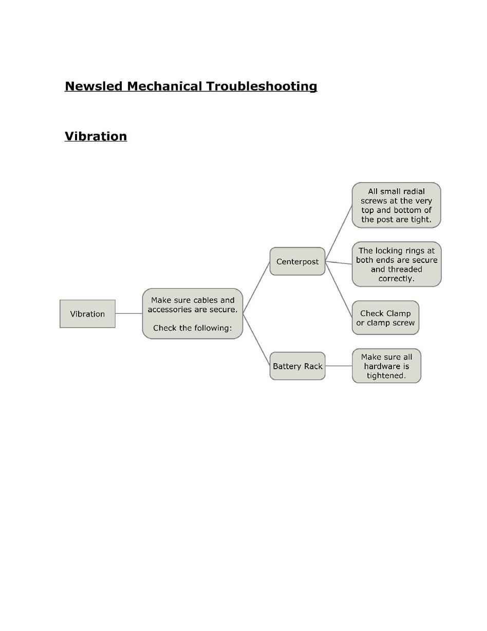
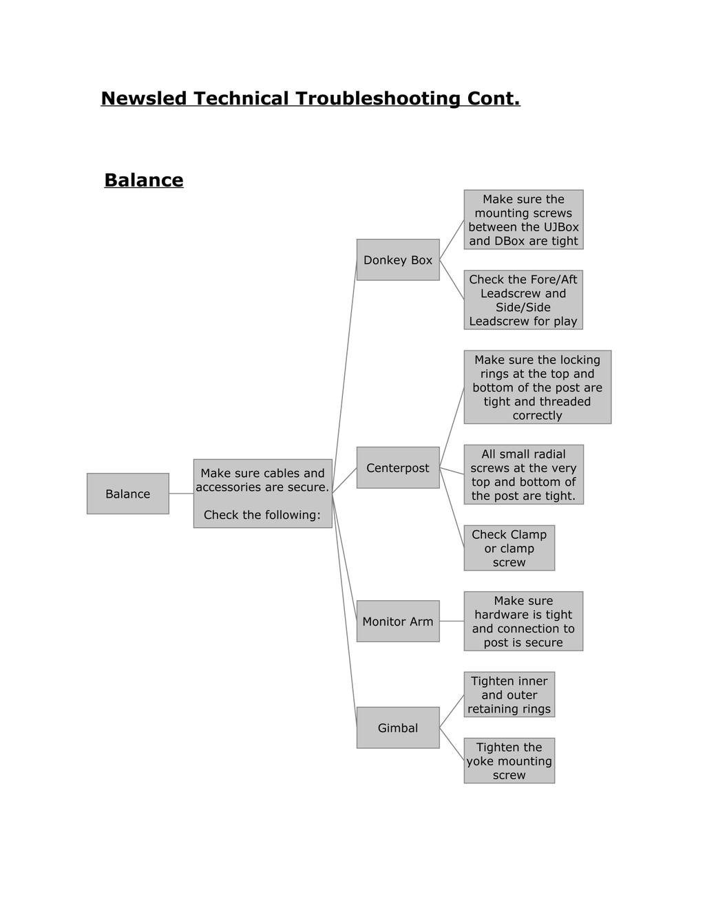
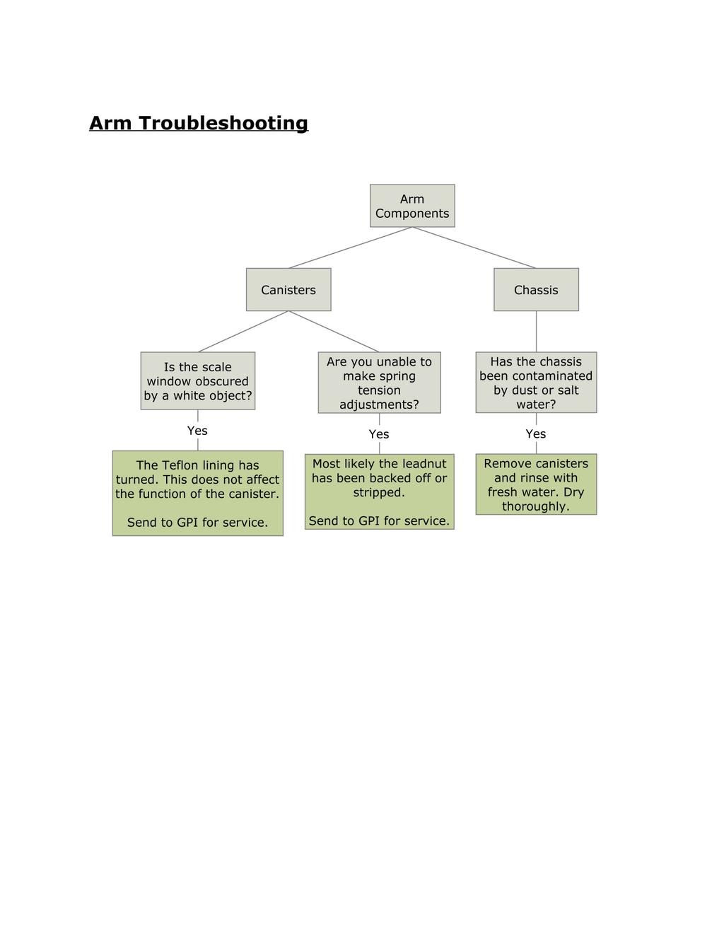
27 TROUBLESHOOTING This section is designed to act as an aid in the unlikely event of system failure. Contrary to popular belief, one does not have to be a technical wizard in order to troubleshoot and repair one s system. The key to troubleshooting lies in the ability to identify the problem, and once this is accomplished, correcting the problem is usually fairly simple. The following charts will help you identify, and then correct most problems that may be encountered. The following should be helpful: 1. Identify the problem. The system performs three (3) functions: Displaying what the camera sees, supplying power to the camera, and controlling the camera and lens. Identify which function is not being performed. 2. Using the following flowcharts, isolate the problem. Remember that while there are three separate functions, they are not always independent of each other. (For example, some video taps are powered by the camera, so if the camera does not have power, there will be no video on the Monitor 28

28 29
29 30
30 31

31 32
32 33
33 34
Instruction Manuall. Flowcam Series. Professional dual-arm Camera Stabilizer System 5-15 lbs
 Flowcam Series Professional dual-arm Camera Stabilizer System 5-15 lbs Instruction Manuall Please read the instruction manual thoroughly before operating your aviator stabilizer for the first time to avoid
Operators Guide. Vision 3 Pan & Tilt Head. Vinten Camera Control Solutions
 Operators Guide Vision 3 Pan & Tilt Head Vinten Camera Control Solutions Vision 3 Pan and Tilt Head Publication Part No. 3543-8 Issue 4 Copyright Vinten Broadcast Limited 2004 All rights reserved throughout
Operators Guide. Vision 11 Pan & Tilt Head. Vinten Camera Control Solutions
 Operators Guide Vision 11 Pan & Tilt Head Vinten Camera Control Solutions Vision 11 Pan and Tilt Head Publication Part No. 3442-8 Issue 1 Copyright Vinten Broadcast Limited 2001 All rights reserved throughout
Contents. QuickStart Guide. p/n LIT
 Contents QuickStart Guide p/n LIT-804000 Camera mounting plate loose Co-Pilot 3.5 monitor and AA battery pack All four screws must be loose to free the camera mounting plate. tight Make sure to tighten
Operators Guide. Vision 100 Pan & Tilt Head. Vinten Camera Control Solutions
 Operators Guide Vision 100 Pan & Tilt Head Vinten Camera Control Solutions Vision 100 Pan and Tilt Head Publication Part No. 3431-8 Issue 3 Copyright Vinten Broadcast Limited 2004 All rights reserved throughout
C-pan arm USERS INSTRUCTIONS
 C-pan arm USERS INSTRUCTIONS Designed 1 of 12 and made in Denmark Thanks for purchasing a 9.Solutions product. With great passion, we design our products to be as versatile as possible. We hope that our
QuickStart Guide. Contents
 Contents QuickStart Guide The Tiffen Company, 90 Oser Avenue, Hauppauge, New York 11788 631-273-2500 800-645-2522 www.tiffen.com Tiffen Steadicam Operations, Glendale, CA 818-843-4600 1-800-593-3331 www.steadicam.com
DUTCH LITE. April 03. If you are missing any of the following items, please contact Stanton Video immediately (602)
") DUTCH LITE April 0 If you are missing any of the following items, please contact Stanton Video immediately (602) 49-9505 1. Dutch Axis Assembly 1. Dutch Lite Motor Assembly 1. Motor Controller MAXIMUM
DUTCH LITE April 0 If you are missing any of the following items, please contact Stanton Video immediately (602) 49-9505 1. Dutch Axis Assembly 1. Dutch Lite Motor Assembly 1. Motor Controller MAXIMUM
Operators Guide. Vision 8 Pan & Tilt Head. Vinten Camera Control Solutions
 Operators Guide Vision 8 Pan & Tilt Head Vinten Camera Control Solutions Vision 8 Pan and Tilt Head Publication Part No. 3441-8 Issue 4 Copyright Vinten Broadcast Limited 2004 All rights reserved throughout
Handheld Video Stabilizer
 Handheld Video Stabilizer INSTRUCTION MANUAL For Demonstration only All rights reserved No part of this document may be reproduced, stored in a retrieval system, or transmitted by any form or by any means,
Vacuum Maintenance Manual (EXCERPT Tim Benedict)
") 1. Position a ladder, scaffold, or work stand, on the right side of Vacuum Skid where the blower motors are installed. 2. Locate the six (6) vacuum hoses connecting the blower motors to the HEPA housings
1. Position a ladder, scaffold, or work stand, on the right side of Vacuum Skid where the blower motors are installed. 2. Locate the six (6) vacuum hoses connecting the blower motors to the HEPA housings
DOWNLOADING THE APP FOR APPLE PHONES: DOWNLOADING THE APP FOR ANDROID PHONES: For Android Phones go to Google Play or the Android Store.
 DOWNLOADING THE APP FOR APPLE PHONES: DOWNLOADING THE APP FOR ANDROID PHONES: For Android Phones go to Google Play or the Android Store. For Apple Phones go to the app store and click GET. Make sure your
TABLE OF CONTENTS SECTION 1 TABLETOP CONFIGURATION SECTION 2 TABLETOP CONFIGURATION ACCESSORIES SECTION 3 SLIDE CONFIGURATION
 S6 USER S MANUAL TABLE OF CONTENTS SECTION 1 TABLETOP CONFIGURATION SECTION 2 TABLETOP CONFIGURATION ACCESSORIES SECTION 3 SLIDE CONFIGURATION SECTION 4 SLIDE CONFIGURATION ACCESSORIES SECTION 5 RACK MOUNT
Zero Gravity Rig Operating Instructions
 Welcome to our new top-of-the-line shoulder support system for cameras up to 15 lbs - the ZG Rig. In addition to its totally unique vertical balancing mechanism, this system is designed to be configurable
Installation Guide Philips MP20/30/40/50/60/70 IntelliVue M-Series Arm Rail Mount Kit
 Installation Guide Philips MP20/30/40/50/60/70 IntelliVue M-Series Arm Rail Mount Kit The purpose of this guide is to: 1. Describe attachment of Table Top Mount to Mounting Adapter on Arm (page 2). 2.
Removal and Installation8
 8 Screw Types 8-4 Top Cover Assembly 8-5 Left Hand Cover 8-6 Right Hand Cover 8-10 Front Panel Assembly 8-14 Left Rear Cover 8-15 Right Rear Cover 8-16 Extension Cover (60" Model only) 8-17 Media Lever
DSLR Nano Handheld Steadycam (DSLR-NANO-QR-BL)
") DSLR Nano Handheld Steadycam (DSLR-NANO-QR-BL) INSTRUCTION MANUAL All rights reserved No part of this document may be reproduced, stored in a retrieval system, or transmitted by any form or by any means,
DSLR Nano Handheld Steadycam (DSLR-NANO-QR-BL) INSTRUCTION MANUAL All rights reserved No part of this document may be reproduced, stored in a retrieval system, or transmitted by any form or by any means,
CHAPTER 5 UNIT MAINTENANCE INSTRUCTIONS
 FPU SYSTEMS OPERATION MANUAL (INCLUDING REPAIR PARTS & SPECIAL TOOL LIST) STANDARD AND SPECIALIZED FPU MODULES BOH FPU Field Pack-up Units CHAPTER 5 UNIT MAINTENANCE INSTRUCTIONS BOH-PM-0-5 06 BOH Environmental
Description: Detailed procedure on removing old bushing and installing new Brake Bushing Replacement Kit 10447
 Procedure: BRAKE BUSHING REPLACEMENT PROCEDURE Product: Document #: Rev: Page: MODEL 7000, 7000A, & 8000 GYRO 078 1 1 of 14 Description: Detailed procedure on removing old bushing and installing new Brake
DSLR NANO Camera Steadycam
 DSLR NANO Camera Steadycam MF-DSLR-NANO-QR I N S T R U C T I O N M A N U A L Copyright Flyboyfilms NV. All rights Reserved Green Hill I Hoge Wei 16 I 1930 Zaventem I Belgium info@movofilms.be I www.movofilms.be
CLIMB2 DUAL MONITOR SIT/STAND WORKSTATION
 CLIMB2 DUAL MONITOR SIT/STAND WORKSTATION CLIMB2 Rev A 3/17 Model CLIMB2-SLV ASSEMBLY AND ADJUSTMENT CLIMB2 PARTS AND TOOLS PLEASE REVIEW these instructions before beginning the assembly and adjustment
DSLR Nano HD Camera Stabilizer (FLCM-DN-HD-QT)
") DSLR Nano HD Camera Stabilizer (FLCM-DN-HD-QT) I NSTRUC TI ON MANUA L For Demonstration Only All rights reserved No part of this document may be reproduced, stored in a retrieval system, or transmitted
DSLR Nano HD Camera Stabilizer (FLCM-DN-HD-QT) I NSTRUC TI ON MANUA L For Demonstration Only All rights reserved No part of this document may be reproduced, stored in a retrieval system, or transmitted
JET RANGER / LONG RANGER INSTALLATION MANUAL. Tyler - Nose Mount For Bell 206 & 206L Series Helicopters FAA STC # SH2256NM
 JET RANGER / LONG RANGER INSTALLATION MANUAL Tyler - Nose Mount For Bell 206 & 206L Series Helicopters FAA STC # SH2256NM PLEASE RETURN THIS MANUAL WITH EQUIPMENT This manual is available for download
Further Information can be found at
 Below is a step by step guide to assembling the Hurricane-Rig. Remember that this is a precision optical instrument. Excessive force can bend critical parts. If treated well it should give many years of
TEC APO 200 OWNER S MANUAL
 TEC APO 200 OWNER S MANUAL 2005 IMPORTANT - PLEASE READ THIS MANUAL BEFORE USING YOUR TELESCOPE SAFETY WARNINGS Do not look at the sun through the telescope! Viewing the sun through the telescope without
G12/G12x USER S MANUAL
 G12/G12x USER S MANUAL TABLE OF CONTENTS SECTION 1 SLIDE CONFIGURATION SECTION 2 SLIDE CONFIGURATION ACCESSORIES SECTION 3 TABLETOP CONFIGURATION SECTION 4 TABLETOP CONFIGURATION ACCESSORIES SECTION 5
skyline 70 Fluid Head OPERATOR S MANUAL #1050 Skyline 70 Fluid Head
 skyline 70 Fluid Head OPERATOR S MANUAL #1050 Skyline 70 Fluid Head Features and Controls Sliding Plate Lock Sliding Plate Pan Handle Clamp Tilt Lock Pan Handle Safety Lock Knob Pan Lock Threaded Stud
AVT Model Tripod.
 AVT Model Tripod www.ravelliphoto.com Product Overview: The Ravelli AVT professional tripod is a high performance, fluid drag tripod that provides smooth continuous drag control and operates on both pan
MK-101 TILE SAW OWNER S MANUAL & OPERATING INSTRUCTIONS SERIAL NUMBER:
 MK-0 TILE SAW OWNER S MANUAL & OPERATING INSTRUCTIONS CAUTION: Read all safety and operating instructions before using this equipment Enter the Serial Number of your new saw in the space below. The Serial
GYRO-ASSIST SETUP MANUAL
 GYRO-ASSIST SETUP MANUAL Tyler Middle Mount II Gyro-Assist for Film or Video cameras. PLEASE RETURN THIS MANUAL WITH EQUIPMENT $50.00 CHARGE FOR MANUAL IF NOT RETURNED. CAN BE DOWNLOADED FROM www.strattoncamera.com
FlowPod Stabilizer / MonoPod / Low Mode
 FlowPod Stabilizer / MonoPod / Low Mode FlowPod Operating Manual Thank you for purchasing the versatile FlowPod, our patented stabilizer/support. The FlowPod offers several shooting options that will help
V40 Videoboom MAIN OPERATING INSTRUCTIONS INDEX 5. SPECIFICATIONS V40 1. INTRODUCTION 2. LIST OF FUNCTIONS AND PARTS
 MAIN OPERATING INSTRUCTIONS V40 Videoboom INDEX 1. INTRODUCTION 2. LIST OF FUNCTIONS AND PARTS 3. INSTRUCTIONS V40 3.1 ASSEMBLY & SETTING UP 3.2 WEIGHT SYSTEM 3.3 MOUNTING THE VIDEO CAMERA 4. USING THE
DS5/DS10/DS20 Fluid Head Operator s Manual. #180 DS5 Fluid Head #182 DS10 Fluid Head #184 DS20 Fluid Head
 DS5/DS10/DS20 Fluid Head Operator s Manual #180 DS5 Fluid Head #182 DS10 Fluid Head #184 DS20 Fluid Head Features and Controls 1/4 and pin carriage Sliding camera plate Slide lock Tilt lock Tilt drag Pan
artemis Cine Broadcast
 1 artemis Cine Broadcast USER MANUAL Date 29. Jan. 2018 2 Imprint Imprint Copyright 2018 Arnold & Richter Cine Technik GmbH & Co. Betriebs KG. All rights reserved. No parts of this document may be reproduced
Cutter Option Installation Instructions
 This kit includes the parts and documentation necessary to install the cutter option on the Zebra XiII, XiIII, and XiIIIPlus-Series printers. NOTE: The Cutter Option is not available for the 96XiIII. Adding
INTRODUCTION. Key Features
 INTRODUCTION Thank you for purchasing the GH-13 Gimbal Tripod Head from Rob Pleas Photography. To get the most out of your tripod head, please read this user's manual thoroughly before use. This user's
Setup Information Panosaurus May 3, 2011
 Setup Information Panosaurus 2.0 www.gregwired.com May 3, 2011 Please take the time to read all of the setup information to ensure success and ease of use of this tripod head. Much of the setup is a one
StealthyPro Instructions
 StealthyPro Instructions 3-point Shooter Mode / Handheld Mode / Monopod Mode Place the black piece between the handle and the silver ring (as pictured). Stabilizer Mode In stabilizer mode, thread the handle
Features and Controls
 Fluid Head OPERATOR S MANUAL 1090 Compassx 2 Fluid Head 1092 Compassx 6 Fluid Head 1093 Compassx 8 Fluid Head 1096 Compassx 10 Fluid Head 1098 Compassx 18 Fluid Head Features and Controls Spare Camera
FG-02 FG-02 LR PICTURED
 FG-02 Fluid-Gimbal Head FG-02 LR PICTURED FG-02 Fluid-Gimbal Head VERTICAL ARM HORIZONTAL BAR SPECIFICATIONS: FG-02 Load Capacity...50 pounds (23kg) Damped Load Capacity...15 pounds (6.8kg) Pan & Tilt
If you are missing any of the following items, please contact Stanton Video immediately (602)
") RIGHT ANGLE FOCUS Jan 03 If you are missing any of the following items, please contact Stanton Video immediately (602) 493-9505 1. Right Angle Focus Servo 2. Servo End Cap 3. Lens Gears (32 pitch, 48 pitch,.6
RIGHT ANGLE FOCUS Jan 03 If you are missing any of the following items, please contact Stanton Video immediately (602) 493-9505 1. Right Angle Focus Servo 2. Servo End Cap 3. Lens Gears (32 pitch, 48 pitch,.6
RD 100. Spare parts list. RD 100 s/n BES Construction Tools PC AB No
 RD 100 Spare parts list RD 100 s/n BES100496 2018 Construction Tools PC AB No. 9800153901 2018-10 General information This spare parts list applies to the following: Part number 8311030410 RD 100 Description
Removal and Installation 8
 Removal and Installation 8 8 Introduction 8-2 Service Calibration Guide to Removal and Installation 8-4 Window 8-8 Covers and Trims 8-12 Rear Tray 8-31 Rear Cover 8-32 Media Lever 8-33 Media Lever Position
2 x Dynamic Arms on 135 Post with C-Clamp
 Installation Guide AWMS-2-D13-C 2 x Dynamic Arms on 135 Post with C-Clamp COMPONENT CHECKLIST RANGE A AWM-LC Post Clamp B AWM-AD Dynamic Arm (x2) C AWM-P13 135 Post D AWM-FC C-Clamp CONTENTS C-Clamp Page
Rob Pleas Photography. GH-13r Gimbal Head. User s Manual
 Rob Pleas Photography GH-13r Gimbal Head ----------------------------- User s Manual INTRODUCTION Thank you for purchasing the GH-13r "retrofit" Gimbal Tripod Head from Rob Pleas Photography. This model
There are two basic applications for the Ikelite DS Sensor. Add an External Strobe. Camera WITHOUT flash connection
 Ikelite DS- i n s t r u c t i o n m a n u a l #4100.5 APPLICATIONS There are two basic applications for the Ikelite DS. Add an External (camera WITHOUT flash connection) Add a Second (camera WITH flash
Zebra XiII-Series Printer Quick Reference Guide
 Zebra XiII-Series Printer Quick Reference Guide Contents Media and Ribbon Loading...67 Media Loading...67 Ribbon Loading...70 Operator Controls...72 Front Panel Keys...72 Front Panel Lights...72 Calibration...74
Design and Manufacture of Video Pipeline Inspection Systems A Full Service Company
 Design and Manufacture of Video Pipeline Inspection Systems A Full Service Company www.rstechserv.com Omni Star LED Pan and Tilt Zoom Color Camera Modell 10-1660 INSTALLATION MANUAL Made in USA IMPORTANT
Olympus Trip 35 Illustrated Repair Instructions
 Olympus Trip 35 Illustrated Repair Instructions Olympus introduced the Trip 35 in 1968. The camera remained in production for 20 years, and Olympus sold over 10 million of them. Both of these numbers must
BE Series. Dual Action Ballhead. You re on steady ground
 BE Series Dual Action Ballhead You re on steady ground 1 Introduction Thank You for choosing Oben! This sturdy Oben BE Series Dual-Action ballhead provides smooth, effortless operation. Two locks provide
SNOWBOARD RACK KIT P/N APPLICATION BEFORE YOU BEGIN KIT CONTENTS. Instr Rev Page 1 of 25
 SNOWBOARD RACK KIT P/N 2881251 APPLICATION Pro Ride RMK 155 and 163, Axys RMK 155, 163, and 174 BEFORE YOU BEGIN Read these instructions and check to be sure all parts and tools are accounted for. Please
Fluid heads perform best when installed on a tripod fitted with a 75mm or 100mm video bowl with leveling base.
 FH-350 Fluid Head FH-350 Fluid Head SPECIFICATIONS: FH-350 Counterbalance Range*...1.6-10 pounds (0.7-4.5kg) Sinusoidal Restoring Torque...Infinite Adjustment, 8-50 inch-pounds Tilt Range... ±90º Damping
User Manual. Binocular Zoom Stereo Microscope with Boom Stand. MicroscopeNet.com
 User Manual Binocular Stereo Microscope with Boom Stand Model W42C1 Series MicroscopeNet.com Table of Contents i. Caution.. 1 ii. Care and Maintenance... 1 1. Component Illustration... 2 2. Installation...3
Installation Guide Mounting Kit for Mounting Philips Avalon CTS Cordless Fetal Transducer System on Wall, 2'' Post, Rail, or Slide-on Mounting Plate
 Installation Guide Mounting Kit for Mounting Philips Avalon CTS Cordless Fetal Transducer System on Wall, 2'' Post, Rail, or Slide-on Mounting Plate The purpose of this guide is to: 1. Describe mounting
GH-50. Gimbal Head. You re on steady ground
 GH-50 Gimbal Head You re on steady ground 1 INTRODUCTION Thank You for choosing Oben! The Oben GH-50 is a gimbal-type tripod head designed to balance a lens along its vertical and horizontal axes. Ideal
BC Series. Dual Action Ballhead. You re on steady ground
 BC Series Dual Action Ballhead You re on steady ground 1 Introduction Thank You for choosing Oben! This sturdy Oben BC Series Dual-Action ballhead provides smooth, precise operation. Two locks provide
TX-3 TILE SAW OPERATION & PARTS MANUAL
 www.mkdiamond.com TILE SAW OPERATION & PARTS MANUAL Revision 00 0.09.009 Caution: Read all safety and operating instructions before using this equipment. This manual MUST accompany the equipment at all
Attaching DX Encoders to your Majestic Carriage
 Attaching DX Encoders to your Majestic Carriage Encoders are the white wheels that you need to have on your carriage in order for the stitch regulation to work. Encoders detect the movement of the machine
3500 Series Tripod Kit
 3500 Series Tripod Kit You re on steady ground 1 INTRODUCTION Thank You for choosing Oben! This versatile and durable Oben tripod and ballhead is a compact and lightweight kit that sets up quickly, folds
Breeze Film Shooting Equipment (P-W5P-BRZ) I N STR UC TI ON MANUAL
 I N STR UC TI ON MANUAL") Breeze Film Shooting Equipment (P-W5P-BRZ) I N STR UC TI ON MANUAL All rights reserved No part of this document may be reproduced, stored in a retrieval system, or transmitted by any form or by any means,
Breeze Film Shooting Equipment (P-W5P-BRZ) I N STR UC TI ON MANUAL All rights reserved No part of this document may be reproduced, stored in a retrieval system, or transmitted by any form or by any means,
COCKPIT DOOR SURVEILLANCE SYSTEM - DESCRIPTION AND OPERATION
 COCKPIT DOOR SURVEILLANCE SYSTEM - DESCRIPTION AND OPERATION 1. General A. The FlightVu video surveillance system is designed to augment aircraft security by providing a secured unobstructed view of the
M-2300-ZX Focus SVT Brake Conversion Kit INSTRUCTION SHEET
 Please contact the Tech Hot Line for the most current instruction information (586) 468-1356!!! PLEASE READ THE FOLLOWING INSTRUCTIONS CAREFULLY PRIOR TO INSTALLATION!!! OVERVIEW: This kit is designed
Handheld Video Stabilizer
 Handheld Video Stabilizer INSTRUCTION MANUAL For Demonstration only All rights reserved No part of this document may be reproduced, stored in a retrieval system, or transmitted by any form or by any means,
PD Way Pan/Tilt Head. You re on steady ground
 PD-117 3-Way Pan/Tilt Head You re on steady ground 1 Introduction Thank You for choosing Oben! This sturdy Oben PD-117 3-Way Pan and Tilt Head offers precise, smooth operation, with independent control
Power Series Camera Support
 Power Series Camera Support Power Jib Power Column Power Dolly Power Series Camera Support Equipment Assembly Manual Remark: Before assemble the jib, please check the inventory and read this manual carefully
ASSET LGA1366 Top-side Probe
 ASSET LGA1366 Top-side Probe (Manual version 1.1) For gaining test access to the debug port of Intel processors that are designed for use in LGA1366 Sockets (Socket B). These include the Intel Core i7
MANUAL. Set-up and Operations Guide Glidecam Industries, Inc. 23 Joseph Street, Kingston, MA Customer Service Line
 MANUAL Set-up and Operations Guide Glidecam Industries, Inc. 23 Joseph Street, Kingston, MA 02364 Customer Service Line 1-781-585-7900 Manufactured in the U.S.A. COPYRIGHT 2015 GLIDECAM INDUSTRIES,Inc.
Quick Start Guide. Basic set-up for your Axis360 system
 Quick Start Guide Basic set-up for your Axis360 system Table of Contents 1 Setting up Slide slider assembly attach belt to cart attach ballhead to cart connect motor to controller attach slider to tripod(s)
SL-35 MARK III INSTRUCTION MANUAL
 SL-35 MARK III INSTRUCTION MANUAL INTRODUCTION The SL-35 Mark III camera is built specifically as a lightweight 35mm Motion Picture Camera. Weighing less than 2.4 kg this new camera is ideal for Steadicam,
NBS-2X NIMBUS STABILIZER QUICK-START GUIDE
 NBS-2X NIMBUS STABILIZER QUICK-START GUIDE PREC AUTIONS Please read and follow these instructions and keep this manual in a safe place. Keep this product away from children. Make sure everything is secure
Boxer HD-2X Motorized Pan Tilt Head (P-BXR-HD-2X)
") Boxer HD-2X Motorized Pan Tilt Head (P-BXR-HD-2X) I N STR UC TI ON MANUAL All rights reserved No part of this document may be reproduced, stored in a retrieval system, or transmitted by any form or by
Boxer HD-2X Motorized Pan Tilt Head (P-BXR-HD-2X) I N STR UC TI ON MANUAL All rights reserved No part of this document may be reproduced, stored in a retrieval system, or transmitted by any form or by
Installation Guide Philips MP60/70 IntelliVue VHM Arm Rail Mount Kit
 Installation Guide Philips MP60/70 IntelliVue VHM Arm Rail Mount Kit The purpose of this guide is to: 1. Describe attachment of Table Top Mount to Mounting Adapter (page 2) 2. Describe attachment of Down
SAVE THESE INSTRUCTIONS
 and Height Mounts Assembly, Installation and Operating Instructions Model Nos. QL, QLA, ARM250, QLM6 and QLAM6 NOTE: Check all parts for shipping damage. In case of shipping damage, DO NOT use. Contact
Micro Force V+F3 ver. 1.1
 Micro Force V+F3 ver. 1.1 Preston Cinema Systems 1659 Eleventh Street Santa Monica, CA 90404 fig 1. V+F3 Controls LEMO receptacle Threaded well for bracket Camera Run Switch Zap Switch Zoom Sensitivity
Model 2704 Parts List * = Standard Equipment 〇 = Circuit Diagram
 2704 11-05 99 98 97 82 88 89 83 84 85 86 87 101 103 100 106 81 71 105 104 73 74 75 76 77 78 80 79 57 62 58 56 63 65 66 67 68 64 69 70 59 60 61 31 30 29 32 34 35 41 40 42 36 37 38 39 43 4445 46 21 22 20
Q2 XBee Handheld Controller Assembly Guide
 Q2 XBee Handheld Controller Assembly Guide Copyright Quantum Robotics Inc. Q2 Controller V1.0 1 Parts List: The kit comes with 14 individual bags. 1. Case Top and Bottom 2. Case Screw Package containing:
9ft Jib Arm with Tripod (P-9-TS)
") 9ft Jib Arm with Tripod (P-9-TS) I NSTRUC TI ON MANUA L All rights reserved. No part of this document may be reproduced, stored in a retrieval system, or transmitted by any form or by any means, electronic,
9ft Jib Arm with Tripod (P-9-TS) I NSTRUC TI ON MANUA L All rights reserved. No part of this document may be reproduced, stored in a retrieval system, or transmitted by any form or by any means, electronic,
Quick Installation Guide
 Full Motion Single Monitor Arm, Pole Mount Quick Installation Guide Please Review the entire Quick Installation Guide prior to installation. If you have any questions regarding the compatibility of this
RESS. Manual. Rotary-Ball-Camera Pro. The Producer. Visual Inspection Sweep Instruments Measuring Instruments
 RESS The Producer Visual Inspection Sweep Instruments Measuring Instruments Manual Rotary-Ball-Camera Pro Summary of the contents Rotary-Ball-CameraPro 1. Commissioning 2. Safety Notes 3. Working with
Adjustments 1 click = 10 mm at 100 m =.36 in at 100 yds Adjustment range (windage and elevation) Dot size 2 MOA 1 Dot intensity settings
 Dot size 2 MOA 1 Dot intensity settings") CompM5 User manual 1 PRESENTATION Aimpoint red dot sights are designed for the two eyes open method which greatly enhances situational awareness and target acquisition. Thanks to the optical design the
CompM5 User manual 1 PRESENTATION Aimpoint red dot sights are designed for the two eyes open method which greatly enhances situational awareness and target acquisition. Thanks to the optical design the
Quick Start Guide V5.1.
 Quick Start Guide V5.1 1 Quick Start Guide Table of Content 1. Package Contents...1 2. Cautions... 1 3. System Requirements... 1 4. Hardware Overview... 2 4.1 Mini Dome Network Camera...2 4.2 IR Mini
Digital Housing. Nikon Coolpix L5 # for. Housing
 Digital Housing i n s t r u c t i o n m a n u a l for Nikon Coolpix L5 Housing #6182.25 Ikelite Digital Housing i n s t r u c t i o n m a n u a l #6182.25 for Nikon CoolPix L5 Please Read We suggest that
Aimpoint PRO User manual
 Aimpoint PRO User manual 1 PRESENTATION Aimpoint sights are designed for the both eyes open method of sighting which greatly enhances situational awareness and target acquisition speed. Thanks to the parallax-free
Outdoor PTZ. Mounting on the Ceiling Using Pendant Mount. Installation Guide. For Models: I93, I94, I95, I96, KCM /12/03
 Outdoor PTZ Mounting on the Ceiling Using Pendant Mount For Models: I93, I94, I95, I96, KCM-8211 2013/12/03 Table of Contents Mounting Solutions... 3 Straight Tube Installation Procedures... 4 Step 1:
MBX INSTRUCTION MANUAL. Please read this manual carefully before using the MBX! Mid-range studio stand
 MBX Mid-range studio stand INSTRUCTION MANUAL EN Please read this manual carefully before using the MBX! CAMBO Thank you for purchasing a Cambo product. This new classed Mid-range studio stand will suit
GHI Systems Rotary Vibration Machine Manual
 GHI Systems Rotary Vibration Machine Manual Version 1.0 Release Date January 2002 Copyright 2002 By GHI Systems, Incorporated 916 N. Western Ave. Suite 201 San Pedro, California No part of this publication
Introduction. Features and Highlights
 Introduction The Nodal Ninja Ultimate M2 Giga (M2G) manual pano head is an ideal solution for capturing high resolution Gigapixel or mosaic type imagery. The M2G will accommodate telephoto lenses up to
Translation Stages Triple-Divide Series
 USER S GUIDE Translation Stages Triple-Divide Series Models 9064 and 9065 U.S. Patent #6,174,102 5215 Hellyer Ave. San Jose, CA 95138-1001 USA phone: (408) 284 6808 fax: (408) 284 4824 e-mail: contact@newfocus.com
Table of Contents: TOPIC: Safe Operation: READ THIS FIRST Page: 3 Warranty 4 Specifications 4 Installation 5-7 Operating Instructions 8 Parts Diagram
 INSTALLATION & OPERATIONS MANUAL FlexArm B-19 FlexArm Inc. Division of Midwest Specialties, Inc. 851 Industrial Drive Wapakoneta, Ohio 45895 419-738-8147 Book Part No 360740 12/2014 1 Table of Contents:
Instruction Manual. Gold Pan Tilt Head with 12V Joystick Control Box (PT-GOLD)
") Instruction Manual Gold Pan Tilt Head with 12V Joystick Control Box (PT-GOLD) All rights reserved No part of this document may be reproduced, stored in a retrieval system, or transmitted by any form or
Instruction Manual Gold Pan Tilt Head with 12V Joystick Control Box (PT-GOLD) All rights reserved No part of this document may be reproduced, stored in a retrieval system, or transmitted by any form or
Product Overview. Features
 APCF1 Model Tripod Product Overview The Ravelli APCF1 is a Professional Quality Carbon Fiber Tripod providing a solid base for high-end photographic equipment. This model is a mix of carbon fiber and magnesium
Assembly and Setup Manual
 M-11 Series Copyboard/C-11 Series Captureboard Assembly and Setup Manual This is the installation and assembly manual for the M-11 series/c-11 series. To the Customer Specialized techniques are required
Digital Housing. Olympus C-740 & C-750 # for. Housing
 Digital Housing i n s t r u c t i o n m a n u a l for Olympus C-740 & C-750 Housing #6130.74 Ikelite Digital Housing i n s t r u c t i o n m a n u a l #6130.74 for Olympus C-740, C-750 Zoom Congratulations
HDCVI Compact Mobile Camera User s Manual
 HDCVI Compact Mobile Camera User s Manual Version 1.0.0 Table of Contents 1 General Introduction... 1 1.1 Overview... 1 1.2 Features... 1 2 Device Framework... 2 2.1 Structure Dimension... 2 2.2 Cable
Mi50 Inverted Microscope User s Manual. Fein.
 Mi50 Inverted Microscope User s Manual Fein info@feinoptic.com Mi50 Microscope Components Siedentopf Trinocular Head Stage Plate Mechanical Stage Locking Screw Hex Wrench Storage Beam Splitter Dust Protector
MAGIXBOX TM. Quick Start Guide
 TM TM by TouchMagix MAGIXBOX TM Quick Start Guide What s in the box: Ankle Ceiling Plate Extendable Rod Connector Piece Middle Piece Universal Spider Super clamp with ball socket Safety Cable Projector
Operators Guide. Pozi-Loc Tripods. Vinten Camera Control Solutions
 Operators Guide Pozi-Loc Tripods Vinten Camera Control Solutions Vision Pozi-Loc Tripods Publication Part No. 3770-8 Issue 3 Copyright Vinten Broadcast Limited 2005 All rights reserved throughout the world.
M40 Microscope User s Manual
 M40 Microscope User s Manual for M40 and M40RT Microscope Components: Trinocular Port Eyepieces Beam Splitter Field Diaphragm Adjustment Aperture Diaphragm Adjustment Filter Slots Analyzer Polarizer Hex
MK-212 SERIES PARTS LIST MODELS: MK Part # MK SPCL Part # SPCL MK Part #
 www.mkdiamond.com MK-1 SERIES PARTS LIST MODELS: MK-1- Part # 191 MK-1--SPCL Part # 191-SPCL MK-1-6 Part # 16 MK-1- Part # 191 MK-1-6 Part # 16 Revision 100 1.016 Manual Part No. 196-PM Caution: Read all
GH-30. Gimbal Head. You re on steady ground
 GH-30 Gimbal Head You re on steady ground 1 INTRODUCTION Thank You for choosing Oben! The Oben GH-30 is a gimbal-type tripod head designed to balance a lens along its vertical and horizontal axes. The