CS IT ports switch basic configuration. Lecture (01) Introduction to 24 ports managed switches By: Dr. Ahmed ElShafee.
|
|
|
- Clyde Jennings
- 5 years ago
- Views:
Transcription


1 Lecture (01) Introduction to 24 ports managed switches By: Dr. Ahmed ElShafee CS IT Agenda 24 ports switch basic configuration Switch remote configuration peer2peer star network clients/server star network Traffic analysis using Packet Tracer ١ Dr. Ahmed ElShafee, ACU : Spring 2016, Practical App. Networks I ٢ ports switch basic configuration ٣ ٤
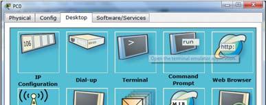


2 Step 1: connecting your PC to the Console Port. Open HyperTerminal software Press RETURN to get started. Switch> (User Mode) ٥ ٦ Step 1 : open CLI from node ٧ ٨


# ٩")

# Step 5: Set the")
 # banner motd")
3 Step 2: To Enter Into Privilege mode/ Versa. Switch>enable Switch# Switch# disable Switch> Step 3: To Enter Into Global Configuration Mode. Switch#config t Switch(config)# ٩ ١٠ Step 4: To change the Host Name of Switch. Switch(config)#hostname SW-FL01-R SWA(config)# Step 5: Set the Message of the Day banner SW-FL01-R01(config) # banner motd #Hello & Welcome to Practical Applications on Networl - Lecture 03# ١١ ١٢
# end SW-FL01-R01> Step 7:")

, Version 12.")


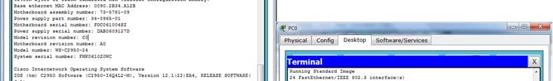
4 Step 6: end configuration session SW-FL01-R01(config)# end SW-FL01-R01> Step 7: version information of the switch SW-FL01-R01#show version Cisco Internetwork Operating System Software IOS (tm) C2950 Software (C2950- I6Q4L2-M), Version 12.1(22)EA4, RELEASE SOFTWARE(fc1) Copyright (c) by cisco Systems, Inc. Compiled. ١٣ ١٤ Step 8: show the current configuration of RAM SW-FL01-R01#show running-config Building configuration... Current configuration : 1056 bytes ١٥ ١٦
5 Step 9: display flash information SW-FL01-R01#dir Directory of flash:/ 1 -rw <no date> c2950-i6q4l2-mz ea4.bin bytes total ( bytes free) ١٧ ١٨ Step 10: To give the IP Address of Management Domain Interface SW-FL01-R01#config t Enter configuration commands, one per line. End with CNTL/Z. SW-FL01-R01(config)#interface vlan 1 SW-FL01-R01(config-if)#ip address SW-FL01-R01(config-if)#no shutdown %LINK-5-CHANGED: Interface Vlan1, changed state to up SW-FL01-R01(config-if)#end SW-FL01-R01# %SYS-5-CONFIG_I: Configured from console by console SW-FL01-R01# Step 11: Display the information of All IP Interfaces on the switch. SW-FL01-R01#show ip interface brief Interface IP-Address OK? Method Status Protocol FastEthernet0/1 unassigned YES manual down down FastEthernet0/2 unassigned YES manual down down FastEthernet0/3 unassigned YES manual down down FastEthernet0/4 unassigned YES manual down down.. FastEthernet0/23 unassigned YES manual down down FastEthernet0/24 unassigned YES manual down down Vlan YES manual up down ١٩ ٢٠

 5 minute input rate 0 bits/sec, 0 packets/sec 5 minute output rate 0 bits/sec, 0 packets/sec 1682 packets input, 530955 bytes, 0 no buffer Received 0 broadcasts (0 IP multicast) 0")
6 Step 12: display management vlan (1) information SW-FL01-R01#show interface vlan 1 Vlan1 is up, line protocol is down Hardware is CPU Interface, address is b34.a12b (bia b34.a12b) Internet address is /8 MTU 1500 bytes, BW Kbit, DLY usec, reliability 255/255, txload 1/255, rxload 1/255 Encapsulation ARPA, loopback not set ARP type: ARPA, ARP Timeout 04:00:00 Last input 21:40:21, output never, output hang never Last clearing of "show interface" counters never Input queue: 0/75/0/0 (size/max/drops/flushes); Total output drops: 0 Queueing strategy: fifo Output queue: 0/40 (size/max) 5 minute input rate 0 bits/sec, 0 packets/sec 5 minute output rate 0 bits/sec, 0 packets/sec 1682 packets input, bytes, 0 no buffer Received 0 broadcasts (0 IP multicast) 0 runts, 0 giants, 0 throttles 0 input errors, 0 CRC, 0 frame, 0 overrun, 0 ignored packets output, 0 bytes, 0 underruns 0 output errors, 23 interface resets 0 output buffer failures, 0 output buffers swapped out ٢١ SW-FL01-R01# Step 13: display Ethernet interface information SW-FL01-R01#show interface FastEthernet0/1 FastEthernet0/1 is down, line protocol is down (disabled) Hardware is Lance, address is 00d0.ff3e.5701 (bia 00d0.ff3e.5701) BW Kbit, DLY 1000 usec, reliability 255/255, txload 1/255, rxload 1/255 Encapsulation ARPA, loopback not set Keepalive set (10 sec) ٢٢ ٢٣ ٢٤
 Trunking Native Mode VLAN: 1 (default) Voice VLAN:")
7 Step 14 : display information of switchport mode of operation of interfaces SW-FL01-R01#show interfaces switchport Name: Fa0/1 Switchport: Enabled Administrative Mode: dynamic Operational Mode: down Administrative Trunking Encapsulation: dot1q Operational Trunking Encapsulation: native Negotiation of Trunking: On Access Mode VLAN: 1 (default) Trunking Native Mode VLAN: 1 (default) Voice VLAN: none Administrative private-vlan host-association: none Administrative private-vlan mapping: none Administrative private-vlan trunk native VLAN: none Administrative private-vlan trunk encapsulation: dot1q. ٢٥ ٢٦ Step 15: save switch configuration into VROM SW-FL01-R01>enable SW-FL01-R01#copy running-config startup-config Destination filename [startup-config]? Building configuration... [OK] Step 16: reboot your switch SW-FL01-R01#reload Proceed with reload? [confirm] %SYS-5-RELOAD: Reload requested by console. Reload Reason: Reload Command. C2950 Boot Loader (C2950-HBOOT-M) Version 12.1(11r)EA1, RELEASE SOFTWARE (fc1) Compiled Mon 22-Jul-02 18:57 by miwang Cisco WS-C (RC32300) processor (revision C0) with 21039K bytes of memory starting ٢٧ ٢٨


8 Step 17 : connect your first PC 1.2 Connecting PCs ٢٩ ٣٠ Step 18: Configuring your PC PC0 item Configuration Gateway DNS Port status On Band width Auto Duplex Auto IP Mask Step 19 : check connectivity to switch ٣١ ٣٢

#login SW-FL01-R01(config-line)#end SW-FL01-R01# %SYS-5-CONFIG_I:")

9 Step 20: telnet server configuration Step 21 : save configuration SW-FL01-R01#config terminal Enter configuration commands, one per line. End with CNTL/Z. SW-FL01-R01(config)#line vty 0 4 SW-FL01-R01(config-line)#password cisco SW-FL01-R01(config-line)#login SW-FL01-R01(config-line)#end SW-FL01-R01# %SYS-5-CONFIG_I: Configured from console by console SW-FL01-R01>enable SW-FL01-R01#copy running-config startup-config Destination filename [startup-config]? Building configuration... [OK] ٣٣ ٣٤ Step 22 : test telnet connection Step 23 : show fa0/1 details ٣٥ ٣٦
10 Step 24 : start configuring switch remotely Step 25 : protecting console connection with password enable config t line console 0 password cisco login enable password cisco enable secret cisco1 copy running-config startup-config reload ٣٧ ٣٨ Commands Summery enabl config t hostname FL01-R01-SW01 banner motd #Hello & Welcome to Practical Applications on Networl - Lecture 03# interface vlan 1 ip address no shutdown enable config t line vty 0 4 password cisco login end 1.3 Build peer2peer star network ٣٩ ٤٠


11 Topology Configuring interface enable config t interface fa0/1 speed 100 duplex full no sh description Floor01-Rack01-Room-1101 end ٤١ ٤٢ Update PC1 configuration PC1 item Configuration Gateway DNS Port status On Band width 100 Duplex Full IP Mask ٤٣ ٤٤


12 Show MAC address table information show mac address-table Ping show mac address-table Configure range of interfaces config t interface range fa0/1-6 speed 100 duplex full end ٤٥ ٤٦ item Configuration item Configuration item Configuration item Configuration Gateway Gateway Gateway Gateway PC1 DNS Port status On Band width 100 Duplex Full PC2 DNS Port status On Band width 100 Duplex Full PC5 DNS Port status On Band width 100 Duplex Full PC6 DNS Port status On Band width 100 Duplex Full IP IP IP IP Mask Mask Mask Mask item Configuration item Gateway Gateway PC3 DNS Port status On Band width 100 Duplex Full PC4 DNS Port status On Band width 100 Duplex Full IP IP ٤٧ Mask Mask ٤٨

13 Show MAC address table information show mac address-table Ping Ping Ping Ping Ping Ping show mac address-table Commands Summery enable config t interface fa0/1 speed 100 duplex full no sh description Floor01-Rack01-Room-1101 end ping show mac address-table show mac address-table Ping Ping Ping Ping Ping show mac address-table copy running-config startup-config reload ٤٩ Config t interface range fa0/1-6 speed 100 duplex full end ٥٠ Topology 1.4 Clients/Server star network ٥١ ٥٢
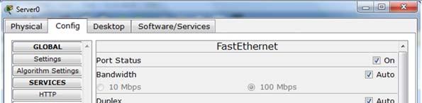
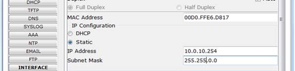


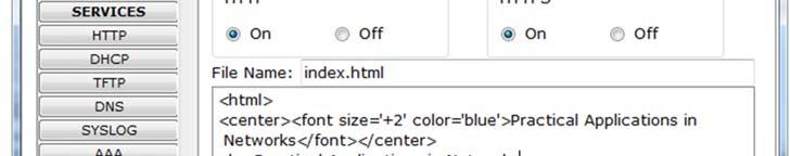


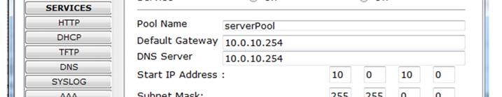
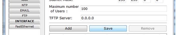

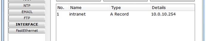
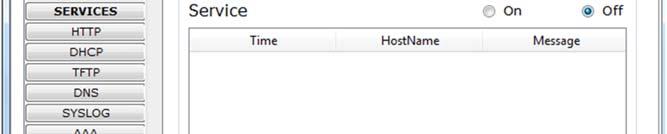
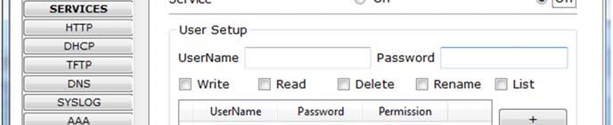
14 Server Configuration ٥٣ ٥٤ ٥٥ ٥٦


15 ٥٧ ٥٨ ٥٩ ٦٠


16 ٦١ ٦٢ item Gateway Configuration item Gateway Configuration Check IP configuration of PCs PC0 DNS Port status Band width Duplex On Auto Auto PC1 DNS Port status Band width Duplex On Auto Auto IP IP Mask Mask item Configuration item Gateway Gateway PC2 DNS Port status Band width Duplex On Auto Auto PC3 DNS Port status Band width Duplex On Auto Auto IP IP ٦٣ Mask Mask ٦٤
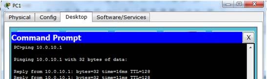

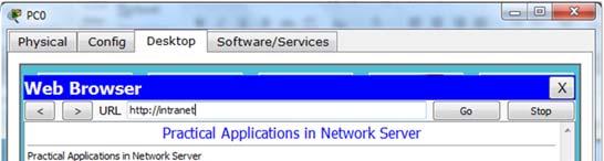

17 Check connectivity Check DNC/http services ٦٥ ٦٦ Check service ٦٧ ٦٨


18 ٦٩ ٧٠ ٧١ ٧٢


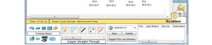
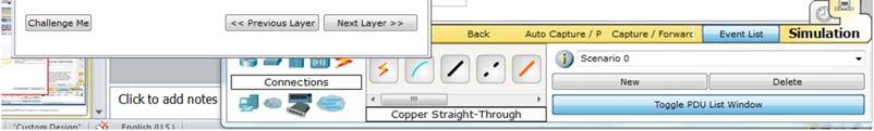
19 ٧٣ ٧٤ Traffic analysis, simple PDU 1.5 Traffic analysis using Packet Tracer 1 ٧٥ ٧٦ Real time mode


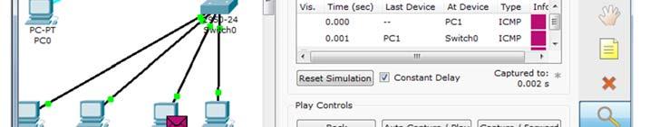


20 ٧٧ ٧٨ ٧٩ Inspection / packet ٨٠ Simulation mode


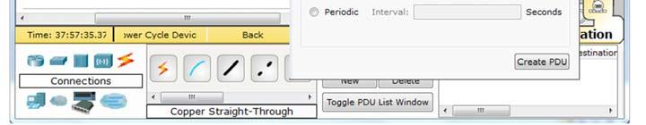
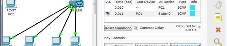

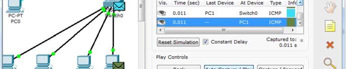
21 Traffic analysis, complex PDU, ping 1 ٨١ ٨٢ ٨٣ ٨٤


22 2 1 ٨٥ ٨٦ 1.6 Traffic analysis, complex PDU, http ٨٧ ٨٨


23 Thanks,.. See you next week (ISA), ٨٩ ٩٠ Dr. Ahmed ElShafee, ACU : Spring 2016, Practical App. Networks I
configuring and connecting 24
 Lecture (01) configuring and connecting 24 ports switch Dr. Ahmed M. ElShafee ١ ٢ Step 1: connecting your PC to the Console Port. Open HyperTerminal software Press RETURN to get started. Switch> (User
Lecture (01) configuring and connecting 24 ports switch
 configuring and connecting 24 ports switch") Lecture (01) configuring and connecting 24 ports switch Dr. Ahmed M. ElShafee ١ ٢ Step 1: connecting your PC to the Console Port. Open HyperTerminal software Press RETURN to get started. Switch> (User
Lecture (01) configuring and connecting 24 ports switch Dr. Ahmed M. ElShafee ١ ٢ Step 1: connecting your PC to the Console Port. Open HyperTerminal software Press RETURN to get started. Switch> (User
Lecture (02) Switch remote configuration peer2peer star network clients/server star network Traffic analysis using Packet Tracer
 Switch remote configuration peer2peer star network clients/server star network Traffic analysis using Packet Tracer") Lecture (02) Switch remote configuration peer2peer star network clients/server star network Traffic analysis using Packet Tracer Dr. Ahmed M. ElShafee ١ Topology ٢ Preparation ٣ Commands summery ٤ enabl
Lecture (02) Switch remote configuration peer2peer star network clients/server star network Traffic analysis using Packet Tracer Dr. Ahmed M. ElShafee ١ Topology ٢ Preparation ٣ Commands summery ٤ enabl
If this is your first time configuring the switch, you will notice that the Switch IOS is almost identical to Router IOS.
 Spanning Tree Lab Objective Create a basic switch configuration and verify it. Determine which switch is selected as the root switch with the factory default settings. Force the other switch to be selected
The objective of this lab is to become familiar with Cisco switches as well as the Spanning Tree Protocol.
 CIS 83 LAB 4 - Spanning Tree Protocol Rich Simms October 3, 2006 Objective The objective of this lab is to become familiar with Cisco switches as well as the Spanning Tree Protocol. Scenario This lab was
PT Activity 2.5.1: Basic Switch Configuration
 Topology NOTE TO USER: This activity is a variation of Lab 2.5.1. Packet Tracer may not support all the tasks specified in the hands-on lab. This activity should not be considered equivalent to completing
Lab Configuring Basic Switch Settings (Solution)
") (Solution) Topology Addressing Table Objectives Device Interface IP Address Subnet Mask Default Gateway S1 VLAN 99 192.168.1.2 255.255.255.0 192.168.1.1 PC-A NIC 192.168.1.10 255.255.255.0 192.168.1.1
(Solution) Topology Addressing Table Objectives Device Interface IP Address Subnet Mask Default Gateway S1 VLAN 99 192.168.1.2 255.255.255.0 192.168.1.1 PC-A NIC 192.168.1.10 255.255.255.0 192.168.1.1
Lab Viewing Network Device MAC Addresses
 Topology Addressing Table Objectives Device Interface IP Address Subnet Mask Default Gateway S1 VLAN 1 192.168.1.1 255.255.255.0 N/A PC-A NIC 192.168.1.3 255.255.255.0 192.168.1.1 Part 1: Configure Devices
BASIC CONFIGURATION CISCO SWITCH
 BASIC CONFIGURATION CISCO SWITCH switch#show running-config ( prikaz trenutne konfiguracije ) switch#show startup-config ( prikaz startne konfiguracije ) switch#configure terminal ( ulaz u global config
This document is exclusive property of Cisco Systems, Inc. Permission is granted to print and copy this document for non-commercial distribution and
 This document is exclusive property of Cisco Systems, Inc. Permission is granted to print and copy this document for non-commercial distribution and exclusive use by instructors in the CCNA Exploration:
Lab - Troubleshooting Connectivity Issues
 Lab - Troubleshooting Connectivity Issues Topology Addressing Table R1 ISP Objectives Device Interface IP Address Subnet Mask Default Gateway G0/1 192.168.1.1 255.255.255.0 N/A S0/0/0 10.1.1.1 255.255.255.252
Lab Exploring Cisco IOS and Configuring Basic Switch Settings
 Topology Addressing Table Objectives Device Interface IP Address Subnet Mask Default Gateway S1 VLAN 99 192.168.1.2 255.255.255.0 192.168.1.1 PC-A NIC 192.168.1.10 255.255.255.0 192.168.1.1 Part 1: Cable
Lecture (03) VLANs 4.0 PC2 PC1 PC4 PC3. By: Dr. Ahmed ElShafee. Topology. Dr. Ahmed ElShafee, ACU : Fall 2015, Practical App. Networks II IP
 VLANs 4.0 PC2 PC1 PC4 PC3. By: Dr. Ahmed ElShafee. Topology. Dr. Ahmed ElShafee, ACU : Fall 2015, Practical App. Networks II IP") Lecture (03) VLANs By: Dr. Ahmed ElShafee 4.0 ١ Dr. Ahmed ElShafee, ACU : Fall 2015, Practical App. Networks II ٢ Topology Gateway Gateway PC1 DNS Port status Band width Duplex On PC2 DNS Port status Band
Lecture (03) VLANs By: Dr. Ahmed ElShafee 4.0 ١ Dr. Ahmed ElShafee, ACU : Fall 2015, Practical App. Networks II ٢ Topology Gateway Gateway PC1 DNS Port status Band width Duplex On PC2 DNS Port status Band
Lab Advanced Telnet Operations Instructor Version 2500
 Lab 4.2.4 Advanced Telnet Operations Instructor Version 2500 Objective Use the telnet command to remotely access other routers. Verify that the application layer between the source and the destination
Switch configuration. By the end of this session, you will be able to: Describe basic switch configuration methods. Configure a switch.
 By the end of this session, you will be able to: Describe basic switch configuration methods. Configure a switch. 4 SESSION OVERVIEW... 2 MANAGEMENT OPTIONS... 3 WHY CONFIGURE SWITCHES?... 4 CONSOLE PORT...
Using Setup Mode to Configure a Cisco Networking Device
 Using Setup Mode to Configure a Cisco Networking Device Setup mode provides an interactive menu to help you to create an initial configuration file for a new networking device, or a device that you have
Configuring Link Aggregation on the ML-MR-10 card
 CHAPTER 34 Configuring Link Aggregation on the ML-MR-10 card This chapter applies to the ML-MR-10 card and describes how to configure link aggregation for the ML-Series cards, both EtherChannel and packet-over-sonet/sdh
IEEE 802.1Q Configuration
 CHAPTER15 This chapter describes: IP Routing over IEEE 802.1Q InterVLAN Routing and 802.1Q Trunking IP Routing over IEEE 802.1Q This section provides procedures for configuring protocols supported with
Lecture (04) VTP Ports Security
 VTP Ports Security") Lecture (04) VTP Ports Security By: Dr. Ahmed ElShafee ١ Dr. Ahmed ElShafee, ACU : Fall 2015, Practical App. Networks II VTP VLAN Trucking Protocol (VTP) is a Cisco proprietary protocol that propagates
Lecture (04) VTP Ports Security By: Dr. Ahmed ElShafee ١ Dr. Ahmed ElShafee, ACU : Fall 2015, Practical App. Networks II VTP VLAN Trucking Protocol (VTP) is a Cisco proprietary protocol that propagates
Configuring IRB. Integrated Routing and Bridging CHAPTER
 CHAPTER 11 This chapter describes how to configure integrated routing and bridging (IRB) for the ML-Series card. For more information about the Cisco IOS commands used in this chapter, refer to the Cisco
Configuring Interfaces
 CHAPTER 4 This chapter describes how to configure interfaces for the Catalyst 4500 series switches. It also provides guidelines, procedures, and configuration examples. This chapter includes the following
Lecture (06) Design and Configuration LAN Practicing, working on CISCO equipment. By: Dr. Ahmed ElShafee
 Design and Configuration LAN Practicing, working on CISCO equipment. By: Dr. Ahmed ElShafee") Lecture (06) Design and Configuration LAN Practicing, working on CISCO equipment By: Dr. Ahmed ElShafee ١ Dr. Ahmed ElShafee, ACU : Fall 2015, Practical App. Networks II Part I ٢ ٣ SW01 steps firstly connect
Lecture (06) Design and Configuration LAN Practicing, working on CISCO equipment By: Dr. Ahmed ElShafee ١ Dr. Ahmed ElShafee, ACU : Fall 2015, Practical App. Networks II Part I ٢ ٣ SW01 steps firstly connect
Lecture (04) Using VLANs to segment LANs. Dr. Ahmed M. ElShafee. Dr. Ahmed ElShafee, ACU Spring 2014, Practical Applications in Computer Networks 4.
 Using VLANs to segment LANs. Dr. Ahmed M. ElShafee. Dr. Ahmed ElShafee, ACU Spring 2014, Practical Applications in Computer Networks 4.") Lecture (04) Using VLANs to segment LANs Dr. Ahmed M. ElShafee ١ 4.0 ٢ Topology ٣ item Configuration item Configuration Gateway Gateway PC1 DNS Port status Band width Duplex On PC2 DNS Port status Band
Lecture (04) Using VLANs to segment LANs Dr. Ahmed M. ElShafee ١ 4.0 ٢ Topology ٣ item Configuration item Configuration Gateway Gateway PC1 DNS Port status Band width Duplex On PC2 DNS Port status Band
Using Setup Mode to Configure a Cisco Networking Device
 Using Setup Mode to Configure a Cisco Networking Device First Published: August 9, 2005 Last Updated: December 3, 2010 Setup mode provides an interactive menu to help you to create an initial configuration
Configuring Interfaces
 CHAPTER 6 This chapter describes how to configure interfaces for the Catalyst 4500 series switches. It also provides guidelines, procedures, and configuration examples. This chapter includes the following
Cisco Introduction to Cisco Networking Technologies Exam. Practice Test. Version 2.2. https://certkill.com
 Cisco 640-821 640-821 Introduction to Cisco Networking Technologies Exam Practice Test Version 2.2 QUESTION NO: 1 Refer to the exhibit. Why was this message received? A. No VTY password has been set B.
Lab - Exploring Router Physical Characteristics
 Topology Objectives Part 1: Examine Router External Characteristics Part 2: Examine Router Internal Characteristics Using Show Commands Background / Scenario In this lab, you will examine the outside of
Lecture (03) VLANs. By: Dr. Ahmed ElShafee. Dr. Ahmed ElShafee, ACU : Fall 2015, Practical App. Networks II 4.0
 VLANs. By: Dr. Ahmed ElShafee. Dr. Ahmed ElShafee, ACU : Fall 2015, Practical App. Networks II 4.0") Lecture (03) VLANs By: Dr. Ahmed ElShafee ١ Dr. Ahmed ElShafee, ACU : Fall 2015, Practical App. Networks II 4.0 ٢ Topology ٣ item Configuration item Configuration PC1 PC2 IP 10.0.2.1 IP 10.0.2.2 item Configuration
Lecture (03) VLANs By: Dr. Ahmed ElShafee ١ Dr. Ahmed ElShafee, ACU : Fall 2015, Practical App. Networks II 4.0 ٢ Topology ٣ item Configuration item Configuration PC1 PC2 IP 10.0.2.1 IP 10.0.2.2 item Configuration
Table of Contents. co Configuring InterVLAN Routing and ISL/802.1Q Trunking on a Catalyst 2900XL/3500XL/2950 Switch Using An Extern
 outing and ISL/802.1Q Trunking on a Catalyst 2900XL/3500XL/2 co Configuring InterVLAN Routing and ISL/802.1Q Trunking on a Catalyst 2900XL/3500XL/2950 Switch Using An Extern Table of Contents Configuring
TELECOMMUNICATION MANAGEMENT AND NETWORKS
 QUAID-E-AWAM UNIVERSITY OF ENGINEERING SCIENCE AND TECHNOLOGY, NAWABSHAH TELECOMMUNICATION MANAGEMENT AND NETWORKS LAB # 3 CONFIGURING INTERFACES OF ROUTER AND SWITCH Topology Diagram Addressing Table
Configuring EtherChannel and 802.1Q Trunking Between Catalyst L2 Fixed Configuration Switches and a Router (InterVLAN Routing)
") Cisco - Configuring EtherChannel and 802.1Q Trunking Between Catalyst L2 Fixed Conf... Page 1 of 13 Configuring EtherChannel and 802.1Q Trunking Between Catalyst L2 Fixed Configuration Switches and a Router
Cisco - Configuring EtherChannel and 802.1Q Trunking Between Catalyst L2 Fixed Conf... Page 1 of 13 Configuring EtherChannel and 802.1Q Trunking Between Catalyst L2 Fixed Configuration Switches and a Router
Management IP Interface
 The management interface is used for the video control plane messages, such as session creation and deletion, between the Logical Edge Devices (LED) and the external Edge Resource Manager (ERM) server.
KIM DONNERBORG / RTS. Cisco Lab Øvelse Af Kim Donnerborg / RTS. Side 0 af 8
 KIM DONNERBORG / RTS Side 0 af 8 INDHOLDSFORTEGNELSE Lab: Basic Router Configuration... 2 Topology Diagram... 2 Addressing Table... 2 Learning Objectives... 2 Scenario... 2 Task 1: Cable the Network....
1 of :22
 Feedback: Help us help you Please rate this document. Excellent Good Average Fair Poor This document solved my problem. Yes No Just Browsing Suggestions to improve this document. (512 character limit)
CCNA Practice test. 2. Which protocol can cause high CPU usage? A. NTP B. WCCP C. Telnet D. SNMP Answer: D
 1. Which network would support at least 30 hosts? A. 10.0.0.0 255.255.255.252 B. 10.0.0.0 255.255.255.240 C. 10.0.0.0 255.255.255.224 D. 10.0.0.0 255.255.255.248 2. Which protocol can cause high CPU usage?
Configuring Gigabit Ethernet Interfaces
 This chapter explains how to configure the Gigabit Ethernet (GE) interface on the Cisco ASR 901 router. Configuring the Interface, page 1 Setting the Speed and Duplex Mode, page 2 Enabling the Interface,
Configuring Interfaces on the ML-Series Card
 5 CHAPTER This chapter describes basic interface configuration for the ML-Series card to help you get your ML-Series card up and running. Advanced packet-over-sonet (POS) interface configuration is covered
Basic Router Configuration
 This section includes information about some basic router configuration, and contains the following sections: Default Configuration, on page 1 Configuring Global Parameters, on page 2 Configuring Gigabit
The configuration of the router at the initial stage was fairly simple (quoting only significant commands, not the entire config):
:") Gentlemen, As was to be expected, Joseph was correct on all accounts. My testbed consisted of a 2811 router running 12.4(24)T4 Advanced IP Services, and two PCs connected to it. One PC was used as the
Gentlemen, As was to be expected, Joseph was correct on all accounts. My testbed consisted of a 2811 router running 12.4(24)T4 Advanced IP Services, and two PCs connected to it. One PC was used as the
This document is exclusive property of Cisco Systems, Inc. Permission is granted to print and copy this document for non-commercial distribution and
 This document is exclusive property of Cisco Systems, Inc. Permission is granted to print and copy this document for non-commercial distribution and exclusive use by instructors in the CCNA Exploration:
Troubleshoot interface down issues in Cisco routers
 Troubleshoot interface down issues in Cisco routers Contents Introduction Prerequisites Requirements Conventions Troubleshoot Methodology Troubleshoot Examples Introduction This document describes troubleshoot
Lecture (08) DHCP server L3 switch By: Dr. Ahmed ElShafee Dr. Ahmed ElShafee, ACU : Fall 2015, Practical App. Networks II
 DHCP server L3 switch By: Dr. Ahmed ElShafee Dr. Ahmed ElShafee, ACU : Fall 2015, Practical App. Networks II") Lecture (08) DHCP server L3 switch By: Dr. Ahmed ElShafee ١ Dr. Ahmed ElShafee, ACU : Fall 2015, Practical App. Networks II Topology 01 ٢ Topology 01 4 DHCP servers ٣ G Floor F0Dest1 F0Edge1 F0AP1 R0 F0AP3
Lecture (08) DHCP server L3 switch By: Dr. Ahmed ElShafee ١ Dr. Ahmed ElShafee, ACU : Fall 2015, Practical App. Networks II Topology 01 ٢ Topology 01 4 DHCP servers ٣ G Floor F0Dest1 F0Edge1 F0AP1 R0 F0AP3
Lab Troubleshooting WAN Connectivity
 Lab 9.2.5 Troubleshooting WAN Connectivity Device Host Name Interface IP Address Subnet Mask Default Gateway R1 R1 Fast Ethernet 0/0 192.168.1.1 255.255.255.0 N/A Serial 0/0/0 (DCE) 192.168.3.1 255.255.255.252
Lab 6.4.1: Basic Inter-VLAN Routing
 Topology Diagram Addressing Table Device (Hostname) Interface IP Address Subnet Mask Default Gateway S1 VLAN 99 172.17.99.11 255.255.255.0 172.17.99.1 S2 VLAN 99 172.17.99.12 255.255.255.0 172.17.99.1
Application Guide. VLANs for improved Q-SYS performance
 Application Guide Rev. A, 6 June 2018 OPTIMIZE Q-SYS PERFORMANCE: CREATE DEDICATED VLANS. One way to greatly ensure the reliability and performance of a Q-SYS network is putting Q-SYS traffic on one or
SEMESTER 2 Chapter 1 Planning and Cabling a Network V 4.0
 SEMESTER 2 Chapter 1 Planning and Cabling a Network V 4.0 135 points 1.1.1 What are the common components between a router and other computers? CPU RAM ROM Operating System 1.1.1.2 What does a router connect?
Configuring Interfaces
 CHAPTER 6 The chapter applies to the ML-Series (ML100T-2, ML100X-8, ML1000-2 cards. This chapter describes basic interface configuration for the ML-Series card to help you get your ML-Series card up and
Configuring IEEE 802.3ad Link Bundling and Load Balancing
 Configuring IEEE 802.3ad Link Bundling and Load Balancing This document describes how the IEEE 802.3ad link bundling and load balancing leverages the EtherChannel infrastructure within Cisco software to
Configuring Interfaces
 CHAPTER 6 This chapter describes how to configure interfaces for the Catalyst 4500 series switches. It also provides guidelines, procedures, and configuration examples. This chapter includes the following
PT Activity 4.4.1: Basic VTP Configuration
 Topology Diagram Addressing Table Device Interface IP Address Subnet Mask Default Gateway S1 VLAN 99 172.17.99.11 255.255.255.0 N/A S2 VLAN 99 172.17.99.12 255.255.255.0 N/A S3 VLAN 99 172.17.99.13 255.255.255.0
CCNA Semester 1 labs. Part 1 of 2 Labs for chapters 1 7
 CCNA Semester 1 labs Part 1 of 2 Labs for chapters 1 7 2.3.3.3 Lab - Building a Simple Network 2.3.3.4 Lab - Configuring a Switch Management Address 3.4.1.2 Lab - Using Wireshark to View Network Traffic
This document is exclusive property of Cisco Systems, Inc. Permission is granted to print and copy this document for non-commercial distribution and
 This document is exclusive property of Cisco Systems, Inc. Permission is granted to print and copy this document for non-commercial distribution and exclusive use by instructors in the CCNA Exploration:
GRE Tunnel with VRF Configuration Example
 GRE Tunnel with VRF Configuration Example Document ID: 46252 Contents Introduction Prerequisites Requirements Components Used Conventions Configure Network Diagram Configurations Verify Troubleshoot Caveats
Lab QoS Manually Configured Frame Relay Traffic Shaping
 Lab 8.1.10.9 QoS Manually Configured Frame Relay Traffic Shaping Objective Scenario Step 1 Failing to perform traffic shaping before injecting traffic into a Frame Relay permanent virtual circuit (PVC)
IPv6 Tunnel through an IPv4 Network
 IPv6 Tunnel through an IPv4 Network Document ID: 25156 Contents Introduction Prerequisites Requirements Components Used Conventions Configure Network Diagram Configurations (Manual IPv6 Mode) Configurations
Lab 5: Inter-VLANs Routing
 Lab 5: Inter-VLANs Routing Network Topology:- Device Interface IP Address Subnet Mask Gateway/Clock Rate Fa 0/0.10 10.5.0.1 255.255.255.192 ----- R1 Fa 0/0.20 10.6.0.1 255.255.255.192 ----- Fa 0/0.30 10.10.0.1
Lab Catalyst 2950T and 3550 Series Basic Setup
 Lab 1.2.9.1 Catalyst 2950T and 3550 Series Basic Setup Objective Configure a Cisco Catalyst 2950T or 3550 series Ethernet switch for the first time using the command-line interface (CLI) mode. Basic first
Configuring the SS7 Q.703 High Speed Port Adapter
 CHAPTER 4 Configuring the SS7 Q.703 High Speed Port Adapter This chapter contains the following sections: Using the EXEC Command Interpreter, page 4-1 Configuring the Interfaces, page 4-2 Checking the
Lab - Configuring Basic Single-Area OSPFv2
 Lab - Configuring Basic Single-Area SPFv2 Topology Addressing Table Device Interface IP Address Subnet Mask Default Gateway G0/0 192.168.1.1 255.255.255.0 N/A R1 S0/0/0 (DCE) 192.168.12.1 255.255.255.252
This document is exclusive property of Cisco Systems, Inc. Permission is granted to print and copy this document for non-commercial distribution and
 This document is exclusive property of Cisco Systems, Inc. Permission is granted to print and copy this document for non-commercial distribution and exclusive use by instructors in the CCNA Exploration:
Configuring the Cisco ASR 1000 Series Modular Ethernet Line Card
 Configuring the Cisco ASR 1000 Series Modular Ethernet Line Card This chapter provides information about configuring the Cisco ASR 1000 Series Modular Ethernet Line Card on the Cisco ASR 1000 Series Routers.
CCNA Semester 2 labs. Part 2 of 2 Labs for chapters 8 11
 CCNA Semester 2 labs Part 2 of 2 Labs for chapters 8 11 8.2.4.5 Lab - Configuring Basic Single-Area OSPFv2 8.3.3.6 Lab - Configuring Basic Single-Area OSPFv3 9.2.2.7 Lab - Configuring and Verifying Standard
Lab 2.5.1: Basic PPP Configuration Lab
 Topology Diagram Addressing Table Device Interface IP Address Subnet Mask R1 R2 R3 Default Gateway Fa0/1 192.168.10.1 255.255.255.0 N/A S0/0/0 10.1.1.1 255.255.255.252 N/A Lo0 209.165.200.225 255.255.255.224
Question 5.1. Every port on a switch is a collision domain. Every port on a router is a collision domain.
 Question 5.1 Q 5.1.1 Number of Collision Domains: = 14 Every port on a switch is a collision domain. Every port on a router is a collision domain. Number of Broadcast Domains: = 5 Every port on a router
Scenarios A P P E N D I X
 A P P E N D I X B Scenarios This appendix contains a set of lab scenarios, each of which contains some type of problem statement that you need to solve. Some scenarios ask specific questions. Others ask
Chapter 5 Lab 5-1, Configure and Verify Path Control
 hapter 5 Lab 5-1, onfigure and Verify Path ontrol Topology Objectives Background onfigure and verify policy-based routing. Select the required tools and commands to configure policy-based routing operations.
Lecture (08) STP - CDP. Dr. Ahmed M. ElShafee CDP STP. tweak this simple design to make it more resilient by adding
 STP - CDP. Dr. Ahmed M. ElShafee CDP STP. tweak this simple design to make it more resilient by adding") Lecture (08) STP - CDP STP CDP Dr. Ahmed M. ElShafee ١ ٢ Such design creates a single point of failure. We could easily tweak this simple design to make it more resilient by adding an extra path between
Lecture (08) STP - CDP STP CDP Dr. Ahmed M. ElShafee ١ ٢ Such design creates a single point of failure. We could easily tweak this simple design to make it more resilient by adding an extra path between
Lab QoS Manually Configured Frame Relay Traffic Shaping
 Lab 8.9.9 QoS Manually Configured Frame Relay Traffic Shaping Objective Failing to perform traffic shaping before injecting traffic into a Frame Relay permanent virtual circuit (PVC) is likely to lead
Chapter 5 Lab 5-1, Configure and Verify Path Control Using PBR. Topology. Objectives. Background. Required Resources. CCNPv7 ROUTE
 hapter 5 Topology Objectives onfigure and verify policy-based routing. Select the required tools and commands to configure policy-based routing operations. Verify the configuration and operation by using
Lab 1. CLI Navigation. Scenario. Initial Configuration for R1
 Lab 1 CLI Navigation This lab covers the most basic skills for accessing and using the command-line interface (CLI) on a Cisco router or switch. Many of the small, picky details of how the CLI works cannot
Lab - Troubleshooting VLAN Configurations (Instructor Version Optional Lab)
") (Instructor Version Optional Lab) Instructor Note: Red font color or gray highlights indicate text that appears in the instructor copy only. Optional activities are designed to enhance understanding and/or
(Instructor Version Optional Lab) Instructor Note: Red font color or gray highlights indicate text that appears in the instructor copy only. Optional activities are designed to enhance understanding and/or
Configuring Management Interfaces on Cisco IOS XR Software
 Configuring Management Interfaces on Cisco IOS XR Software This module describes configuration procedures for management interfaces on the route processors (RPs). Although the management interfaces on
Configuring GRE Tunnel Over Cable
 Configuring GRE Tunnel Over Cable Document ID: 12084 Introduction Before You Begin Conventions Prerequisites Components Used Background Theory Configure Network Diagram Configurations Verify Troubleshoot
Lab 15d. PPPoE Troubleshooting
 MAC: 0:00:00:00:00:0 MAC: 0:00:00:00:00:0 Rev. 0808.88 Lab d. PPPoE Troubleshooting cc na c ookb ook.com T O P O L O G Y & G O A L Client Pool: 0.0.0. 0.0.0. Create a PPPoE connection from an edge router
Lab Configuring Switch Security Features Topology
 Topology Addressing Table Objectives Device Interface IP Address Subnet Mask Default Gateway R1 G0/1 172.16.99.1 255.255.255.0 N/A S1 VLAN 99 172.16.99.11 255.255.255.0 172.16.99.1 PC-A NIC 172.16.99.3
Lab 5: Basic VLAN Configuration
 Topology Diagram Addressing Table Device (Hostname) Interface IP Address Subnet Mask Default Gateway S1 VLAN 99 172.17.99.11 255.255.255.0 N/A S2 VLAN 99 172.17.99.12 255.255.255.0 N/A S3 VLAN 99 172.17.99.13
Lab - Configuring a Switch Management Address
 Topology Addressing Table Objectives Device Interface IP Address Subnet Mask Default Gateway S1 VLAN 1 192.168.1.2 255.255.255.0 N/A PC-A NIC 192.168.1.10 255.255.255.0 N/A Part 1: Configure a Basic Network
Ethernet over GRE Tunnels
 The feature allows customers to leverage existing low end residential gateways to provide mobility services to mobile nodes using Proxy Mobile IPv6 (PMIPv6), General Packet Radio Service (GPRS) Tunneling
Cisco Network Academy CCNA 1 Introduction to Networks
 Cisco Network Academy CCNA 1 Introduction to Networks Packet Tracer Practice with Dans Sample http://www.danscourses.com/ In this lab, you will learn how to configure the following tasks: IPv4 Addressing
Address Resolution Protocol
 The (ARP) feature performs a required function in IP routing. ARP finds the hardware address, also known as Media Access Control (MAC) address, of a host from its known IP address. ARP maintains a cache
CCNA Semester 2 labs. Labs for chapters 2 10
 CCNA Semester 2 labs Labs for chapters 2 10 2.2.2.5 Lab - Configuring IPv4 Static and Default Routes 2.3.2.4 Lab - Troubleshooting Static Routes 3.2.1.9 Lab - Configuring Basic RIPv2 5.2.2.9 Lab - Configuring
Lab Managing the MAC Address Table 2900XL Series
 Lab 6.2.3 Managing the MAC Address Table 2900XL Series Objective Create a basic switch configuration. Manage the switch MAC table. Background/Preparation Cable a network similar to the one in the diagram.
Lab Troubleshooting LAN Connectivity
 Lab 9.2.4 Troubleshooting LAN Connectivity Device Host Name Interface IP Address Subnet Mask Default Gateway Switch Port R1 R1 Fast Ethernet 0/0 192.168.1.1 255.255.255.0 N/A Fast Ethernet 0/2 S1 S1 VLAN
Peter, Please approve us apply a new ISP connection to separate with CCA for ccahalmar. The bandwidth is 100M.
 All test are done in business time. Our testing are not professional. Not like ZBRELLA using www.speedtest.net as professional test. All testing report followed after. 1 From ISP s test shows the connection
Configuring Interfaces
 CHAPTER 9 This chapter describes how to configure interfaces on the Catalyst 6500 series switches. This chapter consists of these sections: Understanding Interface Configuration, page 9-2 Using the Interface,
Lab 3.5.1: Basic Frame Relay
 Lab 3.5.1: Basic Frame Relay Topology Diagram Addressing Table Device Interface IP Address Subnet Mask R1 R2 Default Gateway Fa0/0 192.168.10.1 255.255.255.0 N/A S0/0/1 10.1.1.1 255.255.255.252 N/A S0/0/1
Device Interface IP Address Subnet Mask Default Gateway. Ports Assignment Network
 Felix Rohrer Topology Diagram Addressing Table Device Interface IP Address Subnet Mask Default Gateway S1 VLAN 99 172.17.99.11 255.255.255.0 N/A S2 VLAN 99 172.17.99.12 255.255.255.0 N/A S3 VLAN 99 172.17.99.13
Chapter 6: Network Layer
 Chapter 6: Network Layer Introduction to Networks Intro to Networks v5 Network Layer Intro to Networks v5 2 The Network Layer End to End Transport processes Addressing end devices Encapsulation of Packets
Configuring the SM-1-STM1
 4 CHAPTER To continue your SM-1-STM1 service module installation, you must configure the STM-1 interface. This chapter contains the following sections: Configuring the Interface, page 4-1 Checking the
Chapter 2 Lab 2-1, EIGRP Configuration, Bandwidth, and Adjacencies
 Chapter 2 Lab 2-1, EIGRP Configuration, Bandwidth, and Adjacencies Topology Objectives Background Configure EIGRP on multiple routers. Configure the bandwidth command to modify the EIGRP metric. Verify
Lab - Configuring VLANs and Trunking
 Topology Addressing Table Objectives Device Interface IP Address Subnet Mask Default Gateway S1 VLAN 1 192.168.1.11 255.255.255.0 N/A S2 VLAN 1 192.168.1.12 255.255.255.0 N/A PC-A NIC 192.168.10.3 255.255.255.0
Lab 7 Configuring Basic Router Settings with IOS CLI
 Lab 7 Configuring Basic Router Settings with IOS CLI Objectives Part 1: Set Up the Topology and Initialize Devices Cable equipment to match the network topology. Initialize and restart the router and switch.
Lab 6.2.7a Managing Switch Operating System Files 2900XL Series
 Lab 6.2.7a Managing Switch Operating System Files 2900XL Series Objective Create and verify a basic switch configuration. Backup the switch IOS to a TFTP server and then restore it. Background/Preparation
Chapter 4 Lab 4-1, Inter-VLAN Routing with an External Router
 Chapter 4 Lab 4-1, Inter-VLAN Routing with an External Router Topology Objective Background Configure inter-vlan routing using an external router, also known as a router on a stick. Inter-VLAN routing
Configuring the SS7 Port Adapter
 CHAPTER 4 To continue your SS7 Port Adapter installation, you must configure the card type as either T1 or E1 and then configure the interfaces. This chapter contains the following sections: Using the
Lab - Configuring VLANs and Trunking (Solution)
") (Solution) Topology Addressing Table Objectives Device Interface IP Address Subnet Mask Default Gateway S1 VLAN 1 192.168.1.11 255.255.255.0 N/A S2 VLAN 1 192.168.1.12 255.255.255.0 N/A PC-A NIC 192.168.10.3
(Solution) Topology Addressing Table Objectives Device Interface IP Address Subnet Mask Default Gateway S1 VLAN 1 192.168.1.11 255.255.255.0 N/A S2 VLAN 1 192.168.1.12 255.255.255.0 N/A PC-A NIC 192.168.10.3
This document is exclusive property of Cisco Systems, Inc. Permission is granted to print and copy this document for non-commercial distribution and
 This document is exclusive property of Cisco Systems, Inc. Permission is granted to print and copy this document for non-commercial distribution and exclusive use by instructors in the CCNA Exploration:
Configuring the 4-Port Serial Interface SPA
 This chapter provides information about configuring the 4-Port Serial Interface SPA on Cisco ASR 1000 Series Routers. Configuration Tasks, page 1 Verifying the Interface Configuration, page 11 Configuration
Lab Catalyst 2950T and 3550 Series VTP Domain and VLAN Trunking
 Lab 2.3.7.1 Catalyst 2950T and 3550 Series VTP Domain and VLAN Trunking Objective Configure a VLAN trunk between two Cisco Catalyst WS-C2950T-24-EI switches and a Cisco Catalyst WS-C3550-24-EMI switch
15d. PPPoE Troubleshooting
 Rev. 0800.0900 d. PPPoE Troubleshooting cc na c ookb ook.com PPPoE troubleshooting has been a part of the CCNA longer than certification guide authors have made any serious attempt to cover the topic.