Control TECHNICAL GUIDE 06
|
|
|
- Elizabeth Long
- 6 years ago
- Views:
Transcription


1 Control TECHNICAL GUIDE 06 MH06CT/GB


2 BTicino answers For all the technical or commercial information go to the BTicino site. To send a free fax forward it to
3 CONTENTS Numeric index 2 MY HOME general features 4 General features 4 MY HOME CONTROL 12 GENERAL FEATURES 14 Catalogue 55 General rules for installation 57 Wiring diagram 66 Programming 72 Technical features 81 CONTENTS MY HOME GUIDE CONTROL 1
4 Numeric index Catalogue Configuration Techn. features Item page page page , GSM , N , N , 86 C F F , 86 F452V , 86 F461/ , 86 MH MH MH MH MHGSM , 86 MHROUTER MHSERVER , 86 MHVISUAL 56 - Catalogue Configuration Techn. features Item page page page Catalogue Configuration Techn. features Item page page page 2 NUMERIC CATALOGOINDEX


5 Item Code Page Item Code Page Item Code Page MY HOME GENERAL FEATURES 3 MY HOME GUIDE CONTROL

6 MY HOME The home as you want it MY HOME is a home automation system which offers state-of-the-art solutions, which are in increasing demand in the home and in the service sector. It offers all the house-automation functions and applications concerning comfort, safety, energy saving, communication and control. A common feature of all the MY HOME devices is that they use the same system technology, based on the digital bus, so that the various system components can be combined as the customer chooses and requires. MY HOME MY HOME WEB Services to control and manage the home at a distance MOBILE PHONE FIXED-LINE TELEPHONE CONTROL Web server (audio/video and GSM) Burglar-alarm control unit with Dialling device Telephone switchboard GSM PERSONAL COMPUTER HAND-HELD COMPUTER 4 MY HOME - CONTROL


7 The installation modularity and functional integration of the various devices also allows optimisation of costs, as the user can select which applications he wants to adopt now and which he will choose in the future. MYHOME can, moreover, communicate with the outside world by means of special devices which interact with the home through fixed-line telephones and mobile phones and/or any Personal Computer via local network or Internet. Temperature regulation Energy management Activating the load timetable Burglar-alarm Remote assistance Technical alarms Home CCTV SAVING SAFETY COMMUNICATION HOME COMFORT 2/8 wire digital door entry and video door entry systems Pabx switchboards Sound system Automation of lights and scenarios Automation of shutters Automatic switchboard rearming GENERAL FEATURES 5 MY HOME GUIDE CONTROL

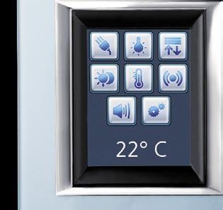
8 MY HOME The home as you want it LIVING Today, the MY HOME system is also available in AXOLUTE styles and can cover all the domotic solutions associated with comfort, security, saving, communication and control. Furthermore, with AXOLUTE, advanced devices such as the colour Touch Screen, the VIDEODISPLAY and the VIDEOSTATION, add images to the control, thus providing the user with a simpler and more intuitive interface. The Bus technology and the configuration of the products have not changed and are common to all systems achieved so far with the LIVING, LIGHT and LIGHT TECH styles. MY HOME Totally free to choose the control MY HOME brings you the maximum choice in selecting the control, thus enabling you to manage your own BASIC CONTROL Enabling and adjusting a single function with: standard controls infrared controls touch controls domotic system; from simple controls to controls for rooms, scenarios and local and remote monitoring. ROOM CONTROL Colour Touch Screen: customizable icons control of all functions of a single room Standard control Touch control Infrared control with Burglar alarm detector Colour Touch Screen Colour Touch Screen 6 MY HOME - CONTROL
9 LIGHT LIGHT TECH AXOLUTE MONITORING CONTROL control of all system functions many customization possibilities simple and intuitive interface thanks to the use of sounds and images via the VIDEO STATION and VIDEO DISPLAY SCENARIO CONTROL The scenarios, complete with all the MY HOME functions, are stored in the scenario module and can be selected from different devices, depending on the user s needs. Touch Screen Scenario control Scenario module VIDEO DISPLAY VIDEO STATION Other devices Standard control GENERAL FEATURES 7 MY HOME GUIDE CONTROL


10 SAFETY The possible functions BURGLAR-ALARM CONTROL UNIT You can monitor the whole house or just one particular room. GAS-STOP DETECTOR Just a small leak and the solenoid valve stops the gas escaping. COMFORT - AUTOMATION TOUCHSCREEN Just one room command for several MY HOME functions. MOTORISED ROLLING SHUTTERS When you wake up you can control the movement of one or more rolling shutters to give more light in the home effortlessly. 8 MY HOME - CONTROL COMFORT - SOUND SYSTEM SOUND SYSTEM AMPLIFIER With a simple movement you can switch the radio on from anywhere in the home and listen to your favourite programme.


11 SAVING - TEMPERATURE REGULATION TEMPERATURE PROBE You can set different temperatures for each room and for every hour of the day. With savings up to 30%. SAVING - ENERGY MANAGEMENT SOCKET WITH ACTUATOR To disconnect the less important loads and avoid a blackout because of an overload. COMMUNICATION MINIATURISED CAMERAS A friendly eye in each room lets you check the whole house. CONTROL WEB SERVER By means of the computer you can control and activate your home even when you are away. TELEPHONE WITH VIDEO SECTION In each device you will find all the communication you need with the interphone, video door entry and telephone functions. GENERAL FEATURES 9 MY HOME GUIDE CONTROL
.")
12 MY HOME WEB My Home Web is the complete range of services which allow the user to manage and control remotely all the My Home functions of the home at any time and with different means of communication, such as a computer connected to the Internet, a hand-held computer or a telephone (fixed or mobile). WHAT MY HOME WEB CAN DO The following functions can be activated with a simple telephone or by connecting to the reserved area of the Internet MY HOME portal: Controls: to manage the lighting, heating, electrical appliances, power and all the automatic devices in the home. Scenarios: to simultaneously activate several predefined commands such as, for example, opening the gate and switching on the driveway lights at the same time, with just one action. A scenario saved in the system can be activated by means of a scenario unit and Web house-automation scenarios. The Web house-automation scenarios are scenarios programmed in the Web pages of the MY HOME portal. Alarms: when there is a dangerous event, the house contacts the telephone numbers and programmed addresses with a telephone call, an SMS and an with audio/video attached and automatically activates by responding to the preset actions (e.g. the automatic switching on of all the lights in the home). Planning: with a single order one can manage the watering or temperature control or simulate the presence of the user in the home. It will be possible to determine the actions that the house shall automatically perform during the days, hours and for the time periods chosen. Archives: MY HOME Web records all the actions and events which have occurred in the home and makes them available for consultation by the user. Images: : to see the rooms of the house taken by the cameras in real time. Answering machine: an event such as a door-entry call can be notified to the user by sending SMS or messages with an audio/ video attachment. The signal can also be consulted by entering the reserved area of the My Home portal. Check: the state of the home functions can be managed to find out, for example, whether the intrusion system is switched on, the lights are on etc.. SMS AND MMS MY HOME PORTAL GSM AND INTERNET ADSL MESSAGE AND VOICE MENU TELEPHONE LINE 10 MY HOME - CONTROL

13 MY HOME WEB The advantages MY HOME WEB can check all the houseautomation functions simply, customisable and conveniently. Simple because the user does not have to remember special passwords to access the service via telephone or computer. Customisable because the user can arrange schedules, WEB domotic scenarios as well as the answering machine introduction message. Convenient because thanks to the MY HOME Portal the services can be used with different means of communication such as a computer and fixed and mobile phones, regardless of the type of device used. Devices such as the telephone actuator, the burglar alarm unit with an integrated dialling device and the telephone dialling device specifically designed for being managed via the telephone line can also be, with MY HOME WEB, controlled with a PC connected to the Internet or with voice commands and SMS s. The MY HOME Web installer can benefit from the advantages offered because, when the customer requests, he can modify the programming, the system parameters and make diagnosis and maintenance remotely. EXAMPLE OF WEB PAGE TO CONTROL THE CAMERAS GENERAL FEATURES 11 MY HOME GUIDE CONTROL


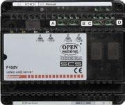
14 MY HOME CONTROL THE NEWS F444 ADSL Modem Router for DIN rail MHSERVER2 2-wire audio/video control and monitoring Web server and SCS MY HOME systems MH300 WiFi ADSL Modem Router 12


15 SECTION CONTENTS 14 General features 55 Catalogue 57 General rules for installation 66 Wiring diagrams 72 Programming 81 Technical features 86 Dimensional data 13 MY HOME GUIDE CONTROL
16 MY HOME Control The BTicino MY HOME CONTROL system can monitor and control your home or office in total safety and privacy thanks to the help of a Personal computer, a fixed-line or mobile phone. You can control what is happening locally or remotely by means of MY HOME portal or point-point. Using simple WEB pages you can command the lights, switch the boiler on or off, see who has rung at the audio handset and check on the CCTV what is happening inside or outside the home. With the BTicino control you can check what is happening for example in the children s bedroom while sitting comfortably at your office desk LOCAL CONTROL The system can command and control the devices of the MY HOME system, using a PC, inside the home itself. Using a simple graphic interface which you can customise you can command lights and rolling shutters, see the pictures of the cameras installed in the various rooms and check any alarms which have occurred. 14 MY HOME - CONTROL


17 REMOTE CONTROL The system can control and monitor the system remotely by means of the MY HOME portal or with point-point connection. The extremely quick, private and safe system can control your home from anywhere else, and can also implement the home CCTV functions. MY HOME WEB: Connection to the system by means of MY HOME portal. The line dedicated to the control system can be either with fixed IP or dynamic IP or a simple telephone line. The MY HOME portal can control your system by connecting to the MY HOME WEB is the Service to control and manage the house remotely. With a simple telephone call, following the voice menu which you can customise, or connecting with a computer or with a hand-held computer to the reserved area of the MY HOME portal you have full control of the house even when you are far away. The MY HOME Internet Portal deals with transmitting orders, keeps the user always up to date on what is happening in the house and on the alarms which have been given with , with attachment audio/video, SMS and voice calls. POINT-POINT CONNECTION: Direct connection to the devices by means of telephone line, ADSL line or with mobile phone (GSM). The ADSL line gives access to the MY HOME system by means of the Internet connecting directly to the fixed IP address of the line dedicated to the control system. The telephone line gives access to the system directly dialling the telephone number of the line to which the control device is connected. Burglar alarm in the living room www Internet MHSERVER2 GENERAL FEATURES 15 MY HOME GUIDE CONTROL
18 MY HOME Control FUNCTIONS PERFORMED BY THE DEVICES ADSL ITEM MHSERVER2 ITEM F452V ITEM F452 FUNCTIONS Automation - lighting ON/OFF * * * - rolling shutters UP/DOWN Burglar alarm * * * Energy Management * * * CCTV * * max 86 cameras + 1 Max 4 cameras Entrance panel camera (connecting the MHSERVER to a 2 wire digital video door entry system) Display the pictures in black and white connected directly to the F452V Display of the pictures in black and white and colour Temperature regulation * * * Sending messages following instrusions and technical alarm * * * Sending an SMS following specific events, * * * requestfor current state, alarms Only with MY HOME portal Only with MY HOME portal Only with MY HOME portal Sending voice calls in case of burglar intrusion and * * * technical alarm Only with MY HOME portal Only with MY HOME portal Only with MY HOME portal Sending with attachment in case of burglar intrusion * * and technical alarm Video door entry answering machine: saving and sending the * message and pictures recorded by the entrance panel with 16 MY HOME - CONTROL

19 GSM GSM + PSTN ANALOGUE TELEPHONE LINE (PSTN) ITEM MHGSM ITEM 3500GSM ITEM 3500 ITEM 3500N ITEM F461/2 * * * * Control of single electric loads * * * * * * * * * * * Only with MY HOME portal Only with MY HOME portal * * * Only with MY HOME portal Only with MY HOME portal * * QUICK SELECTION TABLE MY HOME GUIDE CONTROL 17
. The PC can be connected locally or remotely.")
20 WEB Server My Home can command and control all the combined functions in the home using a PC connected to a local network or to the Internet or through the service MY HOME WEB (with a PC connected to the Internet, an hand-held computer, a fixed-line or a mobile phone). The PC can be connected locally or remotely. The control is performed using the device called Web Server which can work remotely on My Home by means of icons displayed with web pages which can be consulted with a standard navigation program (browser). All the functions in the home (automation, burglaralarm, etc.) lead to the Web Server, by means of the My Home system bus: it is connected to the outside world by the Ethernet network or by connection via modem over a telephone line. From any remote PC the user can operate and control the My Home systems as well as, for example, checking the home by activating the cameras after a burglar-alarm event has been signalled. The control web pages are personalised and the connection parameters configured by means of specific software supplied with the Web Server. MY HOME FUNCTIONS WHICH THE WEB SERVER CAN MANAGE Burglar-alarm Automation Home CCTV MHSERVER Lighting MY HOME portal Management and control of the MY HOME system via PC or an hand-held computer connecting to the MY HOME portal or via fixedline or mobile phone following a voice menu which can be customised Video door entry system Energy management Monitoring, command and control of the system by means of web pages and/or management programs 18 MY HOME - CONTROL
 and can directly interface with a 2 wire video door entry system.")
21 WEB Server MHSERVER2 This device can control and supervise a My Home system installed in the home or office, by means of a Personal Computer connected to a local network or to the Internet or via the MY HOME WEB service (with a PC connected to the Internet, an hand-held computer, a fixed-line or a mobile phone) and can directly interface with a 2 wire video door entry system. GENERAL FEATURES The Web Server can be connected to the control PC by modem and/or local data network or Internet. Using a Personal Computer with commercial browser (e.g. Internet Explorer, Netscape, Opera), the user can connect locally or remotely with the Web Server and, by means of Web pages which can be personalised with icon menus and command pushbuttons, perform the following operations: - supervise and/or command the Automation (management of loads, lights, shutters, etc.) and Energy Management systems; - supervise the Burglar-alarm system by receiving status messages (alarm on the system or no alarm signals); - activate the cameras in the video door entry system to view the picture taken in black and white or colour, being able to alter the picture quality, the shot and the zoom. - display of the pictures and listening to the audio messages sent to the Web Server from the 2 wire audio entrance panel when the Video door entry answering machine function is active. The audio messages and the pictures can also be sent via to an electronic mail address which can be configured with the TiServer program. One can also receive an message with picture attachments, in the mailbox, to signal that events have occurred in the burglar-alarm system (intrusion alarm, technical alarm, etc.). If the MY HOME WEB service is activated the notifications are also given by sending SMS and voice calls. As an alternative to the Web pages, as an alternative to the Web pages, with the aid of the MHVISUAL programme, it is possible to control lights and automation, monitor the Burglar alarm system, control cameras and manage/force the load status of the energy management. With programmes such as Virtual Switch, SCS Action, SCS Action Server and Visual SCS programs installed on a Personal Computer, the Web Server can supervise and control the Automation system (actuations ON/OFF to command lights and/or rolling shutters up/down) by means of icons. GENERAL FEATURES 19 MY HOME GUIDE CONTROL
 and a password known only to the user.")

22 WEB Server MHSERVER2 The Web Server can only connect one user with the My Home system; this is fundamental to guarantee the confidentiality, the coherence and the univocity of the operations performed. Access to the system command pushbuttons is conditional on passing an identification page, which asks for a login (identification name) and a password known only to the user. If the identification is successful the list of all the functions which can be activated and defined when programming the Web Server with the TIMHSERVER2 software can be displayed. Two types of user can access the Web pages: - administrator - user The administrator, as well as navigating in the same pages as the user, can access the CONFIGURATION function and define certain Web Server parameters, such as the number of pictures to be saved in the video door entry answering machine, the address to which alarm signals and/or messages in the answering machine, login and password for access to the pages as user, date, time and time zone and display language of the WEB pages. With control by means of MY HOME WEB service the access is from the MY HOME portal via a double identification. Identification page The privacy of the information exchanged and of the pictures displayed is also guaranteed by the SSL 128 bit protocol. Control Home Page 20 MY HOME - CONTROL

23 EXAMPLE OF THE VIDEO DOOR SYSTEM ANSWERING MACHINE DISPLAY Remote PC to see the message video door entry saved by the WEB Server Internet/LAN www wire video door entry system 2 MHSERVER2 Burglar-alarm system C CCTV Automation Light s Temperature regulation GENERAL FEATURES 21 MY HOME GUIDE CONTROL
24 WEB Server F452 and F452V These devices can control and manage a My Home system installed in the home or office, by means of a Personal Computer connected to a local network or to the Internet or via the MY HOME WEB service (with a PC connected to the Internet, an hand-held computer a fixed-line or a mobile phone). The Web Server can be connected to the control PC by modem and/or local data network or Internet. Using a Personal Computer with commercial browser (e.g. Internet Explorer 5.5), the user can connect locally or remotely with the Web Server and, navigating by means of Web pages which can be personalised with icon menus and command pushbuttons, perform the following operations: As an alternative to the Web pages, as an alternative to the Web pages, with the aid of the MHVISUAL programme, it is possible to control lights and automation, monitor the Burglar alarm system, control cameras and manage/force the load status of the energy management. With programmes such as Virtual Switch, SCS Action Server and Visual SCS programs installed on a Personal Computer, the Web Server can supervise and control the Automation system (actuations ON/OFF to command lights and/or rolling shutters up/down) by means of icons. The Web Servers can also send messages notifying about intrusions and auxiliary alarms detected in the My Home system to the user electronic mailbox. - supervise and/or command the Automation (management of loads, lights, shutters, etc.), Energy Management systems and Temperature control; - supervise the Burglar-alarm system by receiving state messages (alarm on the system or no alarm signals); - with video Web Server Item F452V display the black and white pictures from one of the cameras (maximum 4) connected sent to the Web Server itself. The user can alter the quality of the picture, by adjusting the brightness, the control and the zoom. Burglar alarm siren WEB Server Video (F452V) Home CCTV Rolling shutters up/down Garden lighting BUS SCS LAN F452 F452 F452V Switching on control 22 MY HOME - CONTROL
 and a password known only to the user.")

25 If the MY HOME WEB service is activated the notifications are also given by sending SMS and voice calls. Access to the system command pushbuttons is subordinate to correctly filling in an identification page, which requires a login (identification name) and a password known only to the user. If the identification has been successful you can display the list of all the types of system command and monitoring functions, defined with the TiServer program. In the WEB page you can also set the clock, date, time band and the display language of the WEB pages themselves. The addresses to send notification messages if there has been an intrusion or technical alarm must instead be programmed by means of Software. When controlling by means of the MY HOME WEB service access is from the MY HOME portal via a double identification. Identification page Control Home Page GENERAL FEATURES 23 MY HOME GUIDE CONTROL
26 ADSL Modem Router ADSL Modem routers are devices which allow you to connect the Web Server to an ADSL line. Modem Routers must be programmed with a special software or through Web pages which can be selected from the Browser in use. Bticino ADSL Modem routers also allow you to create a LAN network or a Wi-Fi LAN network within the system. ITEM ADSL line connection LAN Wi-Fi LAN MHROUTER * * 4 DOORS MHROUTER + MH301 * * 3 DOORS * F444 * F444 + C9544 * * 5 DOORS F444 + MH301 * * MH300 * * modem/router F444 MHSERVER2 www Internet MH300 F452V WEB Server MHROUTER LAN Wi-Fi LAN F452 PC Printer Laptop computers hand-held computer 24 MY HOME - CONTROL
27 Modem Router ADSL MHROUTER THE MHROUTER can connect the MY HOME system to the MY HOME portal. To use the MY HOME WEB service connect MHSERVER, F452 or F452V to a fixed IP or dynamic IP ADSL line by means of a correctly configured MHROUTER. It has a 4 port 10/100 Switch for the network connection of PC or printers without using more components. It can be configured via browser or by means of the dedicated configuration program supplied by BTicino with the item. PC1 IP: SM: IP: SM: IP: SM: www Internet Public IP MHROUTER MHSERVER2 F452V F452 PC3 IP: SM: PC2 IP: SM: GENERAL FEATURES 25 MY HOME GUIDE CONTROL
 through an appropriately configured F444 Modem router.")
28 F444 ADSL Modem Router The F444 is a DIN rail ADSL Modem router which allows you to connect the system to the portal MY HOME. In order to use the MY HOME WEB service, it is necessary to connect the WEB Server to an ADSL line (fixed or dynamic IP) through an appropriately configured F444 Modem router. The F444 can be configured with a browser or through a special configuration program supplied by Bticino (included in the item). In order to connect PCs or printers to the network, it is necessary to use the DIN rail (Item C9455) external hub-switch with the F444. PC1 IP: SM: IP: SM: www Internet Public IP F444 IP: SM: C9455 MHSERVER2 F452V F452 PC2 IP: SM: When using only Item F444, it is possible to connect only the WEB Server to the ADSL line. The WEB Server will be directly connected to the LAN port of Item F444. PC4 IP: SM: PC3 IP: SM: MY HOME - CONTROL
29 MH300 ADSL Modem Router The MH300 is a Wi-Fi ADSL Modem router which allows you to connect the system to the MY HOME portal. In order to use the MY HOME WEB service, it is necessary to connect the WEB Server to an ADSL line (fixed or dynamic IP) through an appropriately configured MH300 Modem router. The MH300 can be configured with a browser or through a special configuration program supplied by Bticino (included in the item). IP: SM: PC1 IP: SM: MHSERVER2 F452V F452 LAN www Internet Public IP MH300 IP: SM: PC2 IP: SM: When using PCs (fixed or portable) without the Wi-Fi function, use: - USB Wi-Fi Adapter MH302 for fixed PCs PC3 IP: SM: PCMCIA/Wi-Fi Adapter for Laptops MH303 GENERAL FEATURES 27 MY HOME GUIDE CONTROL

30 Modem Router ADSL MH301 The MH301 is a Wi-Fi access point which allows Wi-Fi connection to systems in which a Bticino Modem router is already installed. The MH301 must be configured before being used in the system. The configuration is achieved through the browser. The MH301 can also be used as a repeater to create Wi-Fi networks in multi-floor houses. For this application, an MH301 is required for each floor of the house. All MH301s must be wired with a LAN cable to the Modem router or Wi-Fi Modem router used for the Internet connection. PC1 IP: SM: IP: SM: MHROUTER www LAN IP: SM: PC3 IP: SM: Internet Public IP MH301 LAN IP: SM: When using PCs (fixed or portable) without the Wi-Fi function, use: - USB Wi-Fi Adapter MH302 for fixed PCs MHSERVER2 F452V F452 - PCMCIA/Wi-Fi Adapter for Laptops MH MY HOME - CONTROL
 you can: - Switch lights on or off - Operate the automatic devices like rolling shutters, shutters, blinds or gates -")

31 MHGSM The device can control, command and monitor your house by means of a mobile phone. By means of SMS or WAP navigation protocol (Wireless Application Protocol) you can: - Switch lights on or off - Operate the automatic devices like rolling shutters, shutters, blinds or gates - Operate/switch off the house electrical appliances - Manage the priority of loads to optimise consumptions, to prevent the tripping of the main switch - Activate house-automation scenarios - Manage alarms from the intrusion system - Manage technical alarms like control of Gas leak, flooding or remote assistance. The SMS or WAP communication is two-way because the user can command the MHGSM remotely and the system gives a warning if there is alarm or a command is performed. Burglar alarm siren Rolling shutters up/down MHGSM MHGSM Garden lighting opening control gate opening control reply that opening has occurred SMS or WAP pages BUS SCS GENERAL FEATURES 29 MY HOME GUIDE CONTROL
32 Burglar alarm control unit with dialling device The telephone dialling device is a device of the MY HOME home automation system, which can automatically dial the telephone numbers previously set and forward one or more pre-recorded messages on the normal telephone line (or GSM if 3500GSM). It allows two-way communication between the user, the burglar-alarm system and the automation system. The programming and the remote use are password (PSW) protected. The PSW is made up of 5 numeric characters and can be customised by the user; if it is not modified it is The password (PSW) must also be entered during an alarm call to send the commands. The burglar-alarm control unit with combined telephone dialling device performs the same functions as the telephone dialling device also combining the burglar-alarm functions. Its functions can be divided into 4 categories: ALARM MANAGEMENT When the burglar-alarm system detects an alarm, it activates to call the numbers set specifying the type of alarm detected; AUTOMATION Following events detected by the burglar-alarm system, it can determine the automatic operation of other devices in the home; ROOM MONITOR When there is an anti-intrusion alarm it can listen to the room and give messages in the rooms controlled by the system; Burglar alarm control unit with dialling devicee item 3500, 3500N and 3500GSM Telephone dialling device e item N4075 TELEPHONE COMMANDS The devices installed in the home can be commanded using the fixed-line or the mobile phone by using predefined codes or via the MY HOME WEB Service (with a PC or an hand-held computer connected to the Internet, a fixed-line or a mobile phone). MAIN FUNCTIONS The telephone dialling device: - allows two-way communication between the user, the burglar-alarm system and the automation system; - when there are particular events such as an alarm (example: intrusion alarm) or system fault, it automatically calls the telephone numbers previously set, specifying by means of pre-recorded messages the type of alarm detected; - commands an automatic operation following an event detected by the burglar-alarm system; - can be called by the user and by means of the open web net commands or simplified commands arranging the operation of devices inside the home; - can be questioned either locally or by telephone, to find out the state of an actuator of the automation system for the lighting and automatic operation functions; - can be questioned by telephone to give information on the state of the burglar-alarm system; - allows continuous monitoring of the system allowing, for example, a communication that there has been a power cut for more than 2 hours; - allows activating the room monitor function: the giving of messages and listening to what happens in the room. Locally just by the dialling device or in all the rooms connecting the dialling device to the BTicino sound system. The device also makes available: - the possibility of setting an extra joker telephone number, common for all the messages, for easier tracing; - automatic recording of the internal memory of the events which have happened and been detected by the system; - can connect with the BTicino MY HOME portal. The MY HOME WEB services, such as sending an when there is an alarm, are thus made available. 30 MY HOME - CONTROL


33 GAS detector Being able to manage technical alarms as well guarantees greater safety in the home even when away for a long time. Automation Lights and rolling shutters can be activated by means of the telephone or be automatically activated following events Automation System Burglar Alarm System MY HOME portal Dangerous events are signalled with , sms or voice call. The user can manage and control the MY HOME system by means of fi xed-line telephone, mobile phone or PC connected to the Internet thanks to the MY HOME WEB service. Item L4600/4 The user is called when there is a: - intrusion alarm - remote call for help alarm - technical alarm (gas-water-temperature) Sound system Connected with the dialling device it can make full use of the ROOM MONITOR function. Wire burglar alarm Is the component which manages the alarms. NOTE: using the burglar-alarm control unit with combined telephone dialling device there is no need to use the fl ush-mounting burglar-alarm control unit item L4600/4 The user can call to: - activate devices - check the system state - listen to sounds in the room - broadcast the voice in the room GENERAL FEATURES 31 MY HOME GUIDE CONTROL
34 Burglar alarm control unit with dialling device and telephone dialling device EXAMPLES OF USE 6 examples of use of the burglar alarm control unit with integrated telephone dialling device and/or of the telephone dialling device are proposed below in INTRUSION ALARM Following an intrusion alarm the dialling device calls the pre-set telephone numbers. graphic form. Remember that each device can supply all the performance indicated simultaneously. TAMPERING ALARM AND SWITCHING ON THE GARDEN LIGHTING Following an tampering alarm the dialling device calls the pre-set telephone numbers and switches on the lamps in the garden. Telephone dialling device Telephone dialling device Relay actuator IR detector Contact interface Garden lighting Alarms Alarms Fixed-line telephone Mobile phone QUESTIONING THE STATE OF THE BURGLAR-ALARM SYSTEM By calling the home number the dialling device can be questioned to receive information on the state of the burglar-alarm system (e.g. on/off, events detected). Fixed-line telephone Mobile phone TECHNICAL ALARM (GAS LEAK) By combining the gas detector in the burglar-alarm system via an interface, when there is a gas leak the dialling device will call and inform the user. Centrale Burglar-alarm Telephone dialling device Telephone dialling device Item L4600/4 Gas detector NOTE: Using the burglar-alarm control unit with combined telephone dialling device there is no need to install the flush-mounting burglar-alarm control unit item L4600/4 32 MY HOME - CONTROL Fixed-line telephone Commands Mobile phone Fixed-line telephone Alarms Mobile phone
35 SWITCHING THE BURGLAR-ALARM SYSTEM ON/OFF REMOTELY The burglar-alarm system can be switched on or off from a remote telephone (e.g. mobile, fixed-line telephone not of the home) or with the MY HOME WEB service (with a PC connected with Internet, a fixed-line or mobile phone). Fixed-line telephone Burglar alarm control unit with Mobile phone MY HOME portal Commands Fixed-line telephone Mobile phone PC Hand-held computer SEND AN ALARM BY MEANS OF MY HOME PORTAL WEB Following an alarm the telephone dialling device sends a call to the preset telephone numbers and connects to the MY HOME portal. The portal will send an , a SMS and a voice call to the numbers programmed: Vocal call Telephone dialling device IR detector MY HOME portal Hand-held computer Alarms SMS SMS Fixed-line telephone Mobile phone GENERAL FEATURES 33 MY HOME GUIDE CONTROL
36 Telephone actuator The telephone actuator can control two users (e.g. boilers, watering the garden, staircase light, garden light, etc.) at a distance by means of the fixed-line telephone or from the mobile phone. The programming and the commands at a distance are PSW protected. The PSW is a 4-figure number code which the customer can customise. If it is not modified it is During programming three different operating modes can be selected: LIGHTING Can be used to activate/deactivate users such as staircase light, garden light, boilers etc. AUTOMATIC OPERATION Can be used to operate the rolling shutter (up/down) motors or other electric motors. TEMPERATURE REGULATION To activate or deactivate the boiler in combination with BTicino timer thermostat Item L4449/N4449 Living and Light series. The activation, deactivation, check and programming commands must only be sent to the actuator from a telephone with touch tone dialling (DTMF), while using telephones with pulse dialling (PD) or rotary dial the actuator does not work. The telephone commands can be sent in the simplified version, with a small number of codes for easier use, or in the complete version according to a standard defined by the Open Web Net protocol. Also, the users can be activated locally using the two pushbuttons (C1 and C2) on the front panel. Up to four actuators in parallel on the line can be installed on the same telephone line to command more than two users. Actuator operation is guaranteed even if there is an answering machine on the telephone line. The actuator can also be installed as an extension on a BTicino PABX telephone switchboard. In this application the users can be controlled both from the extensions and from an external telephone line. When there is a power cut (230V a.c.) the actuator keeps all the programming in the memory, including the state of the relays. garden lighting telephone actuator timer thermostat ItemL4449/N4449 Telephone actuator item F461/2 fixed-line telephone mobile phone 34 MY HOME - CONTROL
37 EXAMPLES OF USE Some examples of telephone actuator operation are proposed below. AUTOMATIC OPERATION MODE Remote control of the up/down of rolling shutters or motor-driven blinds. fixed-line telephone rolling shutter up/down telephone actuator mobile phone LIGHTING MODE Remote control from fixed-line or mobile phone or from extensions connected to the PABX switchboard. extensions fixed-line telephone switching the boiler on mobile phone PABX telephone switchboard telephone actuator watering the garden GENERAL FEATURES 35 MY HOME GUIDE CONTROL
 while a CD containing the TiWeb Software is supplied with the MHGSM module.")
.")
38 Programming software BTicino has developed Software dedicated to programming the Web Servers and the MHGSM module. A CD containing the TiServer Software is supplied with the WEB Servers (item F452, F452V and item MHSERVER) while a CD containing the TiWeb Software is supplied with the MHGSM module. The Software is designed for Windows 98B environments or higher. TISERVER This program supplied with the MHSERVER2 configures them and creates the remote management web pages of the My Home system displayed with standard web navigation programs (browsers). The program can program: - the functions to be displayed and managed on the PC such as CCTV, automation, scenario management etc. - the addresses for the automatic sending of messages linked to events such as burglar alarms or technical alarms - the IP addresses of the MHSERVER2 and the PC for communication within the LAN or Internet. The program can also import the Web Server programming on PC for updates following modifications to the MY HOME system. 36 MY HOME - CONTROL
. The programme allows you to programme: - the functions you need to display and manage from a PC, e.g. CCTV, automation, scenario management, etc.")

39 TISERVER This programme, supplied with the WEB server, allows the programming of these devices as well as the creation of remote management WEB pages of the MY HOME system, displayed with standard browser programmes (browsers). The programme allows you to programme: - the functions you need to display and manage from a PC, e.g. CCTV, automation, scenario management, etc. - addresses to automatically send messages associated with events such as Burglar alarms or Technical alarms - IP addresses of the WEB Server and of the PC for communicating on the LAN network or on the Internet. The programme also allows you to import the WEB Server programming into the PC in order to perform an update in connection with changes made to the MY HOME system. Example of a WEB page programmed with TiServer TIWEB This program supplied with the MHGSM module configures it and creates the remote management WAP pages of the My Home system displayed with WAP navigation programs. The program can program: - the functions to be displayed and managed by means of wap protocol such as automation, management scenarios, lighting and electrical appliances etc. - the mobile phone numbers to automatically send messages linked to events such as burglar alarm or technical alarms - the mobile phone numbers to access and command the system The program can also import the MHGSM programming on PC for updates following modifications to the MY HOME system. Use the TiWEB Software to program the WAP pages which will be shown on the display of the GSM mobile phone GENERAL FEATURES 37 MY HOME GUIDE CONTROL

40 MY HOME WEB MY HOME WEB is the service offered by BTicino to control the house at a distance using any means of communication: a computer connected to the Internet or a fixed-line or mobile phone. All this is possible thanks to the MY HOME portal, which can transmit the commands to the home MY HOME systems and, at the same time, find out in real time what is happening in the house thanks to the signalling of alarm events or by hearing the sounds and seeing the pictures from the rooms of the house. With the MY HOME portal you can control the house at a distance simply and easily in two different ways: - via the Internet, connecting to the MY HOME portal and accessing a special reserved area after giving double identification with login and password which can be customised. - with a telephone (fixed-line or mobile phone), following the indications of a voice menu which can be customised. SMS AND MMS MY HOME PORTAL GSM AND INTERNET ADSL MESSAGE AND VOCAL MENU TELEPHONE LINE 38 MY HOME - CONTROL
41 WHAT MY HOME WEB CAN DO The following functions can be activated with a simple telephone or by connecting to the reserved area of the Internet MY HOME portal: Controls: to manage the lighting, heating, electrical appliances, power and all the automatic devices in the home. Scenarios: to simultaneously activate several predefined commands such as, for example, opening the gate and switching on the driveway lights at the same time, with just one action. A scenario saved in the system can be activated by means of unit scenarios and WEB house-automation scenarios. The WEB house-automation scenarios are scenarios programmed in the WEB pages of the MY HOME portal. Alarms: if there is a dangerous event, the house contacts the programmed telephone numbers and the addresses with a telephone call, a SMS and an with audio/video attachment and automatically reacts with the predefined actions (for example the automatic switching on of all the house lights). Planning: with a single order one can manage the watering or temperature control or simulate the presence of the user in the home. You can define the actions which the house must perform automatically in the days and times and for the periods chosen. Archives: MY HOME WEB records all the actions and events which have occurred in the home and makes them available for consultation by the user. Pictures: to see in real time the rooms of the house filmed by the cameras. Answering machine: a door-entry call can be notified to the user by sending SMS or messages with an audio/video attachment. The signals can also be consulted by entering the reserved area of the MY HOME portal. Check: the state of the home functions can be managed to find out, for example, whether the intrusion system or the lights are switched on, etc... THE ADVANTAGES OF MY HOME WEB MY HOME WEB can check all the house-automation functions simply, conveniently and that may be customised. Simple because the user does not have to remember special passwords to access the service via telephone or computer. It may be customised because the user can program the plannings, the WEB house-automation scenarios and the presentation message for the answering machine. Convenient because thanks to the MY HOME Portal the services can be used with different means of communication such as a computer, hand-held computers and fixed and mobile phones, regardless of the type of device used. Devices such as the telephone actuator, the burglaralarm control unit with combined dialling device and the telephone dialling device expressly designed to be managed by means of telephone line can, with MY HOME WEB, also be commanded by a PC connected to the Internet or with voice commands and SMS. The MY HOME WEB installer can benefit from the advantages offered because, when the customer requests, he can modify the programming, system parameters and diagnosis and maintenance remotely. GENERAL FEATURES 39 MY HOME GUIDE CONTROL
42 MY HOME WEB CHECK THE SYSTEM FEATURES To use the MY HOME WEB service in the home: - There must be at least one solution of the MY HOME system: Lighting, Automation, Burglar-alarm, CCTV and energy management, - One of the following control devices must be installed: Audio/video WEB Server Item MHSERVER Video WEB Server Item F452V WEB Server Item F452 Burglar-alarm control unit with combined telephone dialling device Item 3500/3500N Burglar alarm control unit with integrated GSM telephone dialling device Item 3500GSM Telephone dialling device Item 4075N Chosen on the basis of the features of the system to be controlled and the functions to be performed. - There must be an analogue telephone line or an ADSL broadband connection to connect the devices to the outside world. THE RANGE OF SERVICES As shown in the table below, on the basis of the control remote possibility offered by each device, you can identify five different types of service. To use the MY HOME WEB service with the WEB Server the MHROUTER modem/router, F444 or MH300 must be installed in the system. ITEM MHSERVER ITEM F452V ITEM F452 ITEM 4075N ITEM 3500/3500N/3500GSM FUNCTIONS Commands * * * * Scenarios * * * * Alarms * * * * Temperature control * * * * Planning * * * * Archives * * * * Pictures * * Answering machine * Check * * * * 40 MY HOME - CONTROL
.")
43 HOW TO ACTIVATE MY HOME WEB Activating the MY HOME WEB service is simple and quick. First of all install and test the MY HOME system choosing from the traditional solutions into which the MY HOME offer is divided (comfort, safety, communication, saving and control). During the installation it is a good idea to make a note of the general system data and the devices installed: light point, automation points, scenario units, electrical appliance priority and alarms in the system handbook, it will thus be simpler to configure the portal and the system configuration will always be available. Wherever you are, in the office or at home, on connecting to the MY HOME portal ( and typing your login and password you access your personal area where you enter the general system data, such as address and home owner. The third step is to program the control device and, if using a WEB Server, the MHROUTER modem/router as well. Finally enter the programming of the MY HOME system connecting to the Internet and accessing your reserved area. For more information on the service consult the following pages. 1 3 MHSERVER2 F N 3500GSM 4075N F452V o + MHROUTER F452 o MH300 Installing and testing the MY HOME system Programming the control device and, if using a WEB Server, the MHROUTER modem/router as well. 2 4 Registering the system on the Portal To program the system on the Portal GENERAL FEATURES 41 MY HOME GUIDE CONTROL
44 MY HOME WEB BURGLAR ALARM CONTROL UNIT WITH DIALLING DEVICE ITEM 3500, 3500N, 3500GSM OR TELEPHONE DIALLING DEVICE ITEM 4075N With the Burglar-alarm control unit with dialling device item 3500 or with the telephone dialling device item 4075N the MY HOME WEB service can manage the MY HOME system using a simple telephone line. With the alarm function the user is always kept informed on the alarms which have occurred and he is warned by means of and SMS. He can also manage the comfort solutions at a distance. For example, before the user reaches home he can activate with just one telephone call from the mobile phone the switching on of the driveway lights, opening the garage and the house temperature. Mobile phone Automation SMS MY HOME PORTAL Hand-held computer N 3500GSM 4075N INTERNET PC Lighting VOCAL MENU C Burglar-alarm Heating Mobile phone Fixed-line telephone 42 MY HOME - CONTROL
45 WEB SERVER ITEM F452 Using the WEB Server item F452 with the MY HOME WEB service you can control the MY HOME solutions in the house using the flexibility and the connection offered by the broadband networks (ADSL etc.). To the possibility of managing the Automation and Burglar-alarm functions by direct connection via Internet and WEB control pages, the MY HOME WEB service adds the possibility of managing the WEB SERVER item F452 by telephone commands, SMS messages or . For example a scenario can be created which switches on the house lights and it can be activated with a simple telephone call every time the user wants. In the same way the Planning service can be activated to simulate the presence of the user in the home and thus discourage attempts at intrusion; in this case the MY HOME system in the house will automatically activate a preestablished scenario which, for example, switches on the lights in some rooms in the home. Naturally MY HOME WEB can also use all the services designed to increase safety in the home, managing the Burglar-alarm system and sending signals of alarms or dangerous events in the form of or SMS. To use the MY HOME WEB service with WEB Server item F452, at least one solution of the MY HOME system must be installed in the house. The Modem/Router (item MHROUTER) connected to a broadband network must be installed to communicate with the outside world. SMS Mobile phone MY HOME PORTAL Internet INTERNET www hand-held computer PC F444 VOCAL MENU F452 Mobile phone Fixed-line telephone MH300 Automation modem/router MHROUTER C Lighting Heating Burglar-alarm GENERAL FEATURES 43 MY HOME GUIDE CONTROL
46 MY HOME WEB WEB SERVER VIDEO ITEM F452V This device represents the evolution of the similar item F452, because, as well as performing the Automation, Burglar-alarm and Energy management functions, it can be connected to cameras and thus manage the CCTV function. The user can access his reserved area of the MY HOME WEB portal at any time and via the pictures service display the pictures transmitted by the cameras in the home. If there is a burglar alarm, MY HOME WEB warns the user, sending an with the pictures taken by the cameras and a SMS to the programmed telephone numbers and addresses. To use the MY HOME WEB service with the WEB Server art F452V at least one solution of the MY HOME system must be installed in the house. The Modem/Router (item MHROUTER) connected to a broadband network must be installed to communicate with the outside world. SMS Mobile phone MY HOME PORTAL Internet INTERNET www Hand-held computer PC F444 VOCAL MENU F452V Mobile phone Fixed-line telephone MH300 Automation modem/router MHROUTER C Lighting Heating Burglar-alarm CCTV 44 MY HOME - CONTROL
47 2 WIRE AUDIO/VIDEO WEB SERVER ITEM MHSERVER2 As well as all the services offered by using the WEB Servers item F452 and item F452V with the MY HOME portal this device can also manage the video door entry answering machine service: the user can be informed by means of and SMS every time someone leaves a message on the video door entry answering machine of his home. MY HOME WEB also informs the user of any intrusion. He can find out what is happening in the home receiving an with the audio and video content automatically recorded by the cameras. To use the MY HOME WEB service with item MHSERVER, a MY HOME system solution must be installed in the house. The Modem/ Router (item MHROUTER) connected to a broadband network must be installed to communicate with the outside world. SMS Mobile phone MY HOME PORTAL Internet INTERNET www Hand-held computer PC VOCAL MENU F444 Mobile phone Fixed-line telephone MHSERVER2 Video door entry system MH300 MHROUTER Automation modem/router C Lighting Heating Burglar-alarm CCTV GENERAL FEATURES 45 MY HOME GUIDE CONTROL
48 To 2-wire video door-entry BUS / MY HOME To Burglar alarm system BUS MY HOME WEB Telephone line RJ45 connector Ethernet port EXAMPLE OF CONNECTION TO THE MY HOME PORTAL WITH ADSL LINE The MY HOME WEB can be connected by connecting the system by means of a fixed IP or dynamic IP line. The Bticino modem/router must be used to connect to the system by means of BTicino portal. The ROUTER must be programmed with the data of the line to which the system is connected. Connecting to the www. myhome-bticino.it site and typing the double login and the double identification password accesses seeing and controlling the system. The use of the MY HOME WEB service is advantageous in that the user: - can use a dynamic IP to connect the system. Many operators in fact no longer give users fixed IP private lines, which are, among other things, much more expensive than lines with dynamic IP - can define extra customised WEB scenarios to those already present in the unit scenarios - can program operations planned in the home - can make a safer connection because the connection is protected by 2 logins and 2 passwords - can use the MY HOME WEB service with various means of communication: PC connected to the Internet, fixed-line or mobile phone. a b IN OUT a b PLT1 Telephone line protection F444 MH300 MHROUTER modem/router line ADSL to fixed or dynamic IP MHSERVER2 MHSERVER2 www Internet MY HOME WEB Remote PC www Internet 46 MY HOME - CONTROL


49 Point-point control The point-point control is obtained by connecting directly with the devices by means of analogue telephone line, PC connected to the Internet or mobile phone (GSM). The point-point control can be obtained with all the control devices in the catalogue. EXAMPLE OF POINT-POINT CONNECTION WITH ADSL LINE For the point-point connection the control system must have an ADSL line with fixed IP. The settings vary depending on the operator chosen and the type of connection. To connect to the system type the IP address of the line to which the control device is connected in the browser. To access seeing and managing the system then type the login and the password programmed by means of software TiServer. To 2-wire video door-entry BUS / MY HOME To Burglar alarm system BUS Telephone line RJ45 connector Ethernet port MHSERVER2 a b IN OUT a b PLT1 Telephone line protection MHSERVER2 ADSL FIXED IP www Remote PC Internet GENERAL FEATURES 47 MY HOME GUIDE CONTROL
50 Local control Local control is obtained by connecting to the devices without passing via the telephone line or ADSL. Local control is obtained with the WEB Server using the monitoring and control Software (MHVisual, Visual SCS, Virtual Switch, SCS Action and SCS Action Server) or the WEB pages programmed with the TIMHServer2 or TiServer Software and called with a standard Browser. The MHVisual Software is contained in a CD to be purchased (Item MHVISUAL). Example of local control using the Virtual Switch monitoring and control Software BUS SCS LAN Local PC Local PC Local PC Local PC MHSERVER Switching on control 48 MY HOME - CONTROL
51 The local control can be performed via the Wi-Fi network. The connection can be made through Wi-Fi (wireless) connection to the devices without making use of the telephone line or ADSL. As with the LAN connection, the system can be checked with different Bticino Software packages or with the WEB pages programmed in the Web Server thereof. Example of Wi-Fi local control using the MHVISUAL Software BUS SCS Rolling shutter CCTV Burglar-alarm Hand-held computer Local PC Local PC Local PC Local PC LAN MH301 Access Point Wi-Fi Wi-Fi MHSERVER2 Light Controls and Signalling GENERAL FEATURES 49 MY HOME GUIDE CONTROL

52 Monitoring and control software MHVISUAL This programme makes it possible, through an easily customisable graphical user interface, to control and monitor the devices of the MY HOME system using a PC. In fact, MHVISUAL allows you to create a graphical representation of the system to be checked wherein the real devices are represented with the aid of prearranged icons which can be customised. The programme offers the possibility to check, at all times, the status of the Lighting, Automation and Burglar alarm system as well as the possibility to implement the home CCTV. The application is marketed with the code MHVISUAL. The Software can communicate with MY HOME systems in two ways: - via the L4686 SCS serial interface (or USB-SCS 3559) connected to the PC serial port and to the system BUS; - through an Ethernet network adapter in the PC for accessing one or more Web Servers. 50 MY HOME - CONTROL
53 MODE OF CONNECTION OF THE LOCAL PC TO USE THE MHVISUAL SOFTWARE SERIAL MODE OF CONNECTION The Software can command just one system connecting to the SCS BUS by means of interface L4686 (or USB-SCS interface Item 3559). It can command the lighting, automation and safety system. Lighting Safety BUS SCS C Local PC Item L4686 Temperature control Automation LAN MODE OF CONNECTION The Software can command one or more MY HOME systems from the same local PC by using a HUB and F452, F452V or MHSERVER2 devices. Using the F452V or of the MHSERVER2 the CCTV functions can be implemented. CCTV Safety C BUS SCS Lighting Automation Temperature control Safety Temperature control C Ethernet Ethernet HUB Ethernet BUS SCS Local PC F452 Lighting Automation GENERAL FEATURES 51 MY HOME GUIDE CONTROL

 and with the Web Server Item F452, F452V and Item MHSERVER2, can dialogue with the My Home systems in two ways: - via the interface")
54 Monitoring and control software VISUAL SCS Via an easily personalised graphic interface this program can command and control via PC the My Home system automation and lighting devices. Visual SCS can in fact create a graphic representation of the system to be controlled in which the real devices are represented with the aid of preestablished icons which in any case can be personalised (e.g.: lamp, blinds, fan). The program can also check the state (ON or OFF) of the users represented by the different icon colour at any time. The application supplied with the interface Item L4686 (3559) and with the Web Server Item F452, F452V and Item MHSERVER2, can dialogue with the My Home systems in two ways: - via the interface mentioned connected to the PC serial port and the system BUS; - via an Ethernet card in the PC for access to one or more Web Servers. Example of a synoptic panel to check an individual room Example of a synoptic panel to check the home 52 MY HOME - CONTROL
55 SCS ACTION With a PC the program can create special commands called Scenarios (1) and can activate them daily, weekly or yearly. SCS Action is applied in the public sector and in surroundings where electrical devices must be operated on a periodic basis. An example of use is given by the need to control the switching on of devices, machine tools, industrial heating systems etc. automatically at pre-set times different from those of work, avoiding the use of many traditional timers. Each system to be controlled is connected to the remote PC via Web Server connected to the Ethernet. NOTE: (1) The term Scenario means a particular situation in the surroundings defined ad hoc by the user and represented, e.g., by the operation of some lights, electrical devices, positions of blinds, etc., required to perform a particular activity or to create comfort in the home. SCS ACTION SERVER This program allows several My Home systems connected via Web Server on an Ethernet network to interact. An event or a command given on a system can activate other scenarios created with the SCS Action application in other My Home systems. Because of its flexibility of use this program, like SCS Action, is applied in the public and hotel sectors for the management e.g. of several complex scenarios which cannot be achieved using just the scenario control unit Item N4681 and scenario module (item F420). The scenarios can be activated at a pre-set time or following events generated by the same My Home system, such as activation of burglar-alarm detectors, technical alarms, devices connected to the interfaces Hub Ethernet Local PC WEB Server WEB Server pair pair Automation System Control devices Automation System Control devices SCS cable SCS cable 230V a.c. 230V a.c. Actuators Actuators Fan Electric shutters Lighting Fan Electric shutters Lighting GENERAL FEATURES 53 MY HOME GUIDE CONTROL

56 Monitoring and control software VIRTUAL SWITCH The Virtual Switch program is applied in public open-space surroundings and in large offices where the wall-mounted control points of the lighting and curtains cannot be easily reached from distant workstations. The program can create on the PC monitor a user interface made up of a BTicino Living International cover plate with three virtual switches which allow the personnel to interact with the My Home system without reaching the commands on the wall. The commands are transmitted from the PC to the system to be managed via Ethernet by means of a Web Server device. Workstation Workstation LAN Workstation Workstation WEB Server Switching on control Example of a screen with virtual cover plate and commands 54 MY HOME - CONTROL
57 Control devices MHSERVER2 F452V F452 WEB SERVER Item Description No. of DIN mod. MHSERVER2 WEB Server to monitor 2 wire audio/video systems and MY HOME one-family systems by means of WEB pages on LAN, internet or telephone line - allows two-way communication between user, anti-intrusion system, electrical system, temperature regulation and 2 wire video door entry system. It also implements the CCTV home functions - power supply 230V a.c. F452V WEB Server to monitor and control 6 video systems and SCS systems by means of WEB pages - allows two-way communication between user and SCS system. Implements the home CCTV functions. F452 WEB Server to monitor and 6 control SCS systems by means of WEB pages - allows two-way communication between user and SCS system ADSL MODEM ROUTER MHROUTER F444 C9544 Item MHROUTER F444 C9544 MH300 MH301 MH302 MH303 Description Modem-Router ADSL with integrated 4 port Switch. To be used to connect WEB Servers by means of LAN. DHCP Server enabled. With Power supply and Management Software. DIN rail ADSL Modem Router. To be used for connecting WEB Servers through LAN. Power supply between 10 to 35V d.c. - 6 DIN modules. HUB-Switch to be used with item F444 to create a LAN. Power supply between 10 to 35 V d.c. - 6 DIN modules. Wi-Fi ADSL Modem Router. To be used for connecting WEB Servers to an ADSL. It allows wireless connection to the WEB Server and the creation of a Wi-Fi LAN. Power supply unit and management software included. Wi-Fi Access Point. To be used in systems where an ADSL Modem router is already installed in order to create a Wi-Fi LAN. When used in repeater mode, it allows you to create Wi-Fi networks on different floors of a house. Power supply unit included. USB/Wi-Fi interface to be used with fixed PCs with no Wi-Fi features. PCMCIA/Wi-Fi interface to be used with Laptops with no Wi-Fi features. MH300 MH301 MH302 MH303 CATALOGUE MY HOME GUIDE CONTROL 55
58 Control devices MHGSM Item Description No. of DIN mod. MHGSM GSM module to monitor and 6 control SCS systems by means of SMS and WAP. - allows two-way communication between user and SCS system. MHGSM N 3500GSM BURGLAR-ALARM CONTROL UNIT WITH DIALLING DEVICE Item Description 3500 Burglar alarm unit with integrated telephone dialling device. 3500N Burglar alarm unit with integrated telephone dialling device. Set up for the connection of the new Bticino stereo sound system. 3500GSM Burglar alarm unit with integrated GSM telephone dialling device. Set up for the connection of the new Bticino stereo sound system. When there is no GSM signal reception, the dialling device can be connected to the PSTN telephone line. Module with GSM antenna included. TELEPHONE ACTUATOR Item Description No. of DIN mod. F461/2 telephone actuator with 2 relays 3 independent with contact in switchboard, power supply 230 V a.c. F461/2 MONITORING AND CONTROL SOFTWARE Item MHVISUAL Description Monitoring and control software for MY HOME systems. It allows you to locally control MY HOME applications. MHVISUAL 56 MY HOME CONTROL
59 MHSERVER 2 My Home Server GENERAL RULES FOR INSTALLATION MHSERVER2 Mode of connecting the Web Server to the remote Personal Computer For the Personal Computer to dialogue with the Web Server it must be fitted with an Ethernet network card or a modem. The Personal Computer and the Web Server can be connected with the following types of connection: in LAN in internet with modem/router MHROUTER (fixed or dynamic IP) in internet with ADSL modem (fixed IP) by means of the PSTN local telephone line in internet with PSTN modem CONNECTIONS AND INSTALLATION LIMITS The MHSERVER2 must be connected to: to the electrical mains 230V a.c., 50/60 Hz; Bticino Burglar alarm BUS (terminal 1-2); the video door-entry system BUS, Bticino 2-wire (terminal 7-8); to the Ethernet communication network and/or local telephone line. Installation and maintenance must only be carried out by trained personnel. Use insulated screwdrivers and do not touch the terminals directly to avoid electrostatic discharges. Comply with the following installation warnings: Do not install the Web Server in damp surroundings (e.g. laundries, swimming pools, and damp surfaces) or near heat sources (radiators, cookers or heaters). Do not install the devices in excessively dusty areas or where there are corrosive vapours. Room temperature from +5 to +40 C, relative humidity from 20% to 80% not condensing. CONNECTION IN LAN If the Web Server is directly connected to just one PC, it is connected using a crossed UTP cable. If the Web Server is connected to one or more Personal Computers via a Local Ethernet network (LAN), it is connected by a concentrator device (HUB) and by an uncrossed UTP cable. When using Wi-Fi devices, it is necessary to use a Wi-Fi Access Point (MH301) in the system. However, in order to achieve communication between the Personal Computer and the WEB Server, it is necessary to configure both devices, thus providing a consistent static IP address and Subnet Mask (belonging to the same class ). LAN Ethernet My Home system BUS Access Point MH301 GENERAL RULES FOR INSTALLATION MY HOME GUIDE CONTROL 57
60 MHSERVER 2 My Home Server MHSERVER 2 My Home Server GENERAL RULES FOR INSTALLATION MHSERVER2 CONNECTION THROUGH INTERNET WITH MHROUTER (FIXED OR DYNAMIC IP) In this case, the WEB Server is connected to the public telephone line by means of an MHROUTER modem/router. To activate MY HOME WEB service, a fixed or dynamic IP ADSL connection needs to be established. Telephone line www LAN ISP Internet Ethernet My Home system BUS ADSL Modem Router MHRouter CONNECTION THROUGH INTERNET WITH ADSL MODEM (FIXED IP) In this case, the WEB Server is connected to the public telephone line by means of an ADSL (Asymmetric Digital Subscriber Line) modem/router. To access the necessary functions from your PC, a connection with any ISP (Internet Service Provider) needs to be established, and the ADSL modem/ router needs to be appropriately configured. Telephone line ADSL Modem/Router ISP www Internet Ethernet My Home system BUS 58 MY HOME - CONTROL
61 MHSERVER 2 My Home Server MHSERVER 2 My Home Server CONNECTION THROUGH TELEPHONE LINE Using the public telephone line and the WEB Server internal modem, a Point-to-Point connection with a remote PC fitted with a modem can be established. The connection is established from the remote PC using the Windows remote access function, specifying, instead of the Internet Service Provider (ISP) telephone number, the telephone number to which the WEB Server internal modem answers. Telephone line telephone pair Modem My Home system BUS CONNECTION THROUGH INTERNET Connection through the Internet with a PSTN modem (only to send e- mails through the modem) This function uses the public telephone line and the WEB Server internal modem to activate a temporary connection with the remote PC to send an following events such as: burglar alarm system technical alarms call from the video door entry entrance panel. The s are sent to an electronic mail box, managed by an Internet Service Provider (ISP), whose configuration parameters (POP server address, login, and password) are specified in the TiWEB programme Setup section. If the remote PC is configured to manage the via the Internet, the user will be alerted in real time whenever the above-mentioned events occur in his/her home. The user will then be able to interact more with his/her home, establishing the connection to the WEB Server and enabling, through Internet Explorer, the display of the pictures sent by one of the video cameras installed in the room involved. Telephone line telephone pair ISP www Internet My Home system BUS GENERAL RULES FOR INSTALLATION MY HOME GUIDE CONTROL 59
62 GENERAL RULES FOR INSTALLATION F452, F452V and MHGSM The Ethernet cable should not be a crossover cable (pin to pin) if the WEB Server is connected to a 10BASE T-type HUB. It should be a crossover cable if the WEB Server is connected directly (point-to-point) to a PC. If the correct cable is used, the green LED of the device will flash (more or less fast) whenever network traffic is detected. During the first installation and whenever the setting of the WEB Server or the GSM module needs to be modified, the interface cable (item ) needs to be connected to the PC serial port. The same cable will have to be used in case of an upload of the setting already saved in the WEB Server or in the GSM module and whenever the firmware is upgraded. WARNINGS Installation and maintenance procedures shall be carried out by qualified personnel only. Use insulated screwdrivers and do not touch the terminals to prevent electrostatic discharges. Do not install the WEB Server or the GSM module near water (for example, laundries, swimming pools, damp surfaces) or heat sources (radiators, stoves, heaters). Do not install the device in particularly dusty places or in the presence of corrosive vapours. Room temperature from +5 to +40 C, relative humidity ranging between 20% and 80%, non-condensating. The WEB Server installation requires a connection: - to the mains by means of a dedicated power supply item (for item F452V) or item (for item F452); - to the video camera(s) of the CCTV system (only for WEB Server item F452V); - to the automation system bus; - to the 10BASE T Ethernet communication network. The GSM module installation requires a connection: - to the mains by means of a dedicated power supply item to the automation system BUS; - to the GSM network by inserting the SIM Card in the appropriate housing INSTALLATION AND MAIN OPERATIONS 1. Carry out wiring operations as described below and in the following page. 2. Install the TiServer programme (for items F452 and F452V) or the TiWEB programme (for item MHGSM) on the PC which will be used for the configuration. The PC should be connected to the WEB Server or the GSM module through the serial port using item (please see the TiWEB or TiServer user manual). 3. Define the static (fixed) IP address of the WEB Server and the Subnet Mask of the Ethernet network to which the device will be connected (for items F452 and F452V). F452 INSTALLATION RULES 230Va.c. Reset F452 Ethernet Reset SCS 12V OK 230Va.c. NO F452 Ethernet SCS 12V NO NOTE: connect the Automation system power supply item E46ADCN and the WEB Server power supply item to a common two-pole switch. T 230Va.c. Reset F E46ADCN Ethernet SCS 12V NO Automation BUS F452 Ethernet Reset SCS 12V 60 MY HOME - CONTROL
63 F452V INSTALLATION RULES 230Va.c. A Reset BC D F452V Ethernet SCS BUS 2 1 Carry out wiring operations in an orderly way If a power supply feeding the SCS BUS is already present, do not connect the WEB SERVER to the BUS terminals of item Reset A BC D NO F452V Ethernet SCS 2 1 NO T Do not move devices which may cause electromagnetic interferences close to the WEB Server video MHGSM INSTALLATION RULES C IN IN V OPEN web net Do not move the BUS cable close to the GSM antenna 230Va.c. NOTE: connect the Automation system power supply item E46ADCN and the MHGSM power supply item to a common switch Carry out wiring operations in an orderly way SIM card C IN IN V OPEN web net NO Do not move devices which may cause electromagnetic interferences close to the MHGSM T C IN IN V OPEN web net SIM card Do not move the power supplies of the Burglar alarm and Automation systems close to the MHGSM Automation BUS NOTE: to ensure correct functioning, the device should be installed in an area where the GSM signal of the chosen telephone provider is good. For additional information on the strength of the GSM signal or the use of an external antenna, please see the Installation Manual. WARNING: antenna connection operations and the SIM card insertion and removal must be carried out when the device is not being supplied. GENERAL RULES FOR INSTALLATION MY HOME GUIDE CONTROL 61
64 GENERAL RULES FOR INSTALLATION- Burglar alarm control unit with dialling device and telephone dialling device The dialling device can be installed in any room in the home, in an easily accessible area for easy modification of settings or reading of events. The dialling device can be installed on the wall using the fastening plate. Box 503 Fastening to the plate A To remove the dialling plate from the plate lower the tab and push upwards. A Telephone line Cable fastening hole 1 OK SCS pair 2 OK Or flush-mounted in a Multibox switchboard Pair for BTicino BUS (item L4669S) 1 Installation kit complete with frames Telephone line 2 3 Flush-mounting box OK OK After establishing the exact point where the dialling device must be installed set up the system; trunking for the passage of the cables for BUS and telephone system, flush-mounting box and any finishings if installed in MULTIBOX switchboards. Before fastening it, make the connections as described in the technical features terminal board connection, insert and connect the back-up battery in the compartment on the back and for installation in MULTIBOX move the tamper jumper from -/T1 to - /T2. NOTE: detailed information on the installation in Multibox switchboards can be found in the instruction sheets with the switchboards themselves. 62 MY HOME - CONTROL
65 USABLE CABLE The sheathed, non-shielded, twisted telephone pair or the red BTicino SCS pair for burglar alarm system (item L4669S) should be used to connect the device. The power supply, the operating signals and the alarm signals are distributed through this pair. Interrupting or sabotage of the connections causes an immediate system alarm. The BTicino pair (Item L4669) is 300/500V insulated and therefore can be tubed with 230V a.c. cables Telephone pair SCS red pair for burglar alarm system (item L4669S) BACK-UP BATTERY Connect the battery Item 3507/6 to the connector in the compartment on the back of the dialling device, after the battery has been put in the compartment itself and then connect to the BUS, to avoid the battery discharging uselessly. Back-up battery connection Item 3507/6 POSITION IN THE SYSTEM The telephone dialling device must be the first component of the internal telephone system: it must be connected immediately downstream of the line protection fuses and of the surge arrester. Dialling device Telephone Fax Fuse Discharge OK Example of the connection of the telephone dialling device inside a home. GENERAL RULES FOR INSTALLATION 63 MY HOME GUIDE CONTROL
66 OPEN PROTOCOL FOR ELECTRIC NETWORKS GENERAL RULES FOR INSTALLATION Telephone actuator USE Activation, deactivation and check commands The activation, deactivation and check commands must only be sent to the actuator from a telephone with touch tone dialling (DTMF) connected to the fixed-line or the mobile network (mobile phone), while using telephones with pulse dialling (PD) or rotary dial the actuator does not work. Two types of command can be sent to the telephone actuator: Simplified commands Commands formed of a small number of characters to type. Complete commands (Open Web Net) Commands formed of a large number of characters. These commands belong to the BTicino Open Web Net protocol and are common to all the products belonging to the My Home family. To use the actuator, the PROG/LINE selector (on the front part) should be moved to LINE and the green light should be permanently on. Activation, disabling, and check controls can be sent from an external line. Using the check command one can check the operating condition of the user (activated or deactivated) from a fixed-line or mobile telephone line. If an answering machine is also present on the same telephone line, all actuators should be set to answer after the answering machine, setting a higher number of rings than those set for the activation of the answering machine. The actuators only answer after a valid number of consecutive rings (call from outside telephone line or internal call from extension connected to the switchboard) which is the same as those programmed (base 5) while invalid rings are those produced by an auto-dial call. Simplified commands for remote operation from telephone This is the simple version of the activation, deactivation and check commands. These are made up of a limited number of characters, for easy use. These commands can activate, deactivate or check the state of the relays of the main and secondary actuators and are valid for all modes - lighting, automatic operation and temperature regulation. LOCALE COMMANDS THROUGH FRONT PUSHBUTTONS The C1 and C2 pushbuttons allow to control (activate and deactivate) the relays in relation to the mode and function set. The C1 pushbutton activates relay 1, the C2 pushbutton activates relay 2. C1 230V 0,5A 2A C2 5A cos=0,5 6A C1 C2 C1 C2 F461/2 PROG LINEA 230V 50 ma 50 Hz PRI a LU b 64 MY HOME - CONTROL
67 OPEN PROTOCOL FOR ELECTRIC NETWORKS OPEN PROTOCOL FOR ELECTRIC NETWORKS OPEN PROTOCOL FOR ELECTRIC NETWORKS OPEN PROTOCOL FOR ELECTRIC NETWORKS OPEN PROTOCOL FOR ELECTRIC NETWORKS OPEN PROTOCOL FOR ELECTRIC NETWORKS OPERATION AND TEST EXAMPLES Garden lighting, lighting mode and pulse operation (monostable relay, e.g. for 2 minutes) Garden lighting, lighting mode and switch on-switch off operation (bistable relay) ON C1 C2 C1 C2 230V 0,5A 2A 5A cos=0,5 6A 230V 0,5A 2A 5A cos=0,5 6A C1 C2 C1 C2 C1 C2 F461/2 F461/2 PROG LINEA PROG LINEA 230V 50 ma 50 Hz 230V 50 ma 50 Hz PRI a LU b PRI a LU b ON C1 C2 C1 C2 230V 0,5A 2A 5A cos=0,5 6A 230V 0,5A 2A 5A cos=0,5 6A C1 C2 C1 C2 C1 C2 F461/2 F461/2 PROG LINEA PROG LINEA 230V 50 ma 50 Hz 230V 50 ma 50 Hz PRI a LU b PRI a LU b After 2 minutes OFF C1 C2 C1 C2 230V 0,5A 2A 5A cos=0,5 6A 230V 0,5A 2A 5A cos=0,5 6A C1 C2 C1 C2 C1 C2 F461/2 F461/2 PROG LINEA PROG LINEA 230V 50 ma 50 Hz 230V 50 ma 50 Hz PRI a LU b PRI a LU b GENERAL RULES FOR INSTALLATION MY HOME GUIDE CONTROL 65
68 WIRING DIAGRAMS MHSERVER2 DIAGRAM 1 CONNECTION TO THE 2-WIRE VIDEO DOOR-ENTRY AND MY HOME SYSTEM MHSERVER2 * A = 1 PF = 1 ON OFF L4565 Flush-mounted amplifier Burglar-alarm system 3499 Line terminator MHSERVER 2 ON BUS N 1 P ON BUS N 2 P RJ45 connector Ethernet port * The device must be programmed PIVOT handset PIVOT handset F441 OUT1 OUT2 OUT3 OUT4 OUT IN Lighting Automation Load control Temperature control IN1 IN2 IN3 IN4 S C S BUS Va.c. Video EP BUS P N Z wire COAX interface BUS P N Z wire COAX interface SI 1 OUT F422 12V 1 V 12V 1 V I1 I2 I3 I4 MOD IN F500 Radio tuner P N T S 9 BUS PL S+ S- S1 P 1 N Z Colour TUBE camera P 2 N Z Colour TUBE camera 66 MY HOME - CONTROL
69 DIAGRAM 2 CONNECTION TO THE TELEPHONE LINE To the Bticino Burglar alarm system To the 2-wire video door-entry and MY HOME system Telephone line RJ45 connector Ethernet port MHSERVER2 a b IN OUT a b PLT1 Telephone line protection MHSERVER2 DIAGRAM 3 CONNECTION TO THE TELEPHONE LINE AND TO THE BURGLAR ALARM CONTROL UNIT WITH DIALLING DEVICE ITEM 3500/3500N/3500GSM OR TO THE TELEPHONE DIALLING DEVICE ITEM 4075N Burglar alarm control unit with integrated dialling device item 3500/3500N/3500GSM Telephone dialling device item 4075N a LU b T1 a b To the Bticino Burglar alarm system a b IN OUT a b PLT1 2 Telephone line Telephone line protection 2 RJ45 connector Ethernet port MHSERVER2 To the 2-wire video door-entry and MY HOME system Tamper T1 T2 + C S in S out NOTE: set the number of rings for the answer more than the number of rings set for the MHSERVER MHSERVER2 WIRING DIAGRAMS MY HOME GUIDE CONTROL 67
70 WIRING DIAGRAMS F452, F452V and MHGSM DIAGRAM 1 F452V - CONNECTION IN SERIES OF THE CAMERAS NO NO NO * * * * C C C - + Optional whenever a light is to be switched on when the video camera is selected * 230V~ 230V~ 230V~ NO 230V~ C NO C 1 2 NO C 1 2 NO C 1 2 NO C As regards the cable length and section, please see the instruction sheet supplied with the Item Reset A B C D A B C D As for the connection of internal and external video cameras, use signal converter module, Item Internal / external camera Ethernet SCS 2 1 BUS ART (coax) V COAX + 230V~ Video signal converter DIAGRAM 2 F452V - STAR CONNECTION OF THE CAMERAS * Optional whenever a light is to be switched on when the video camera is selected * * NO 230V~ NO 230V~ NO * C C C 230V~ * NO C V~ NO C 1 2 NO C 1 2 NO C 1 2 NO C Maximum distance 150 m. For wiring 7-8 use a twisted pair, sect. 0,28 mm 2 or the 0.35 mm 2 twisted pairs of cable Item ; for wiring 1-2 use a twisted or non-twisted pair with section 028 mm 2 or above. Reset 2 1 As for the connection of internal and external video cameras, use signal converter module, Item A B A B C D C 8 7 D Internal / external camera Ethernet SCS 2 1 BUS ART (coax) V COAX + 230V~ Video signal converter 68 MY HOME - CONTROL
71 DIAGRAM 3 F452 - CONNECTION TO THE MY HOME SYSTEM Ethernet Reset SCS 12V NOTE: connect power supply item E46ADCN of the Automation system and power supply item to a standard switch. 230Va.c. LAN Control devices 2 BUS 230Va.c. Actuators DIAGRAM 4 MHGSM - CONNECTION TO THE MY HOME SYSTEM C IN IN V OPEN web net 2 NOTE: connect power supply item E46ADCN of the Automation system and power supply item to a standard switch Va.c. Control devices SIM card BUS 230Va.c. Actuators WIRING DIAGRAMS MY HOME GUIDE CONTROL 69
72 OPEN PROTOCOL FOR ELECTRIC NETWORKS OPEN PROTOCOL FOR ELECTRIC NETWORKS WIRING DIAGRAMS Telephone actuator DIAGRAM 1 DIRECT CONNECTION TO THE TELEPHONE LINE max. 230Va.c. 6A resistive 2A inductive max. 230Va.c. 6A resistive 2A inductive user 2 user 1 C1 C2 Telephone line 230V 0,5A 2A 5A cos=0,5 6A a b IN C1 C2 F461/2 PROG LINEA Telephone actuator Item F461/2 OUT a b 230V 50 ma 50 Hz PRI LU a b 230Va.c. 50 Hz 2 Telephone protection Item PLT1 DIAGRAM 2 CONNECTION TO THE TELEPHONE LINE SUPPLIED WITH THE BTICINO TIMER THERMOSTAT ITEM L4449/N4449 Remote activation Closed contact manual antifreeze program Open contact automatic program (last selected) Timer thermostat Item L/N4449 NA C NC C1 C1 230V 0,5A 2A F461/2 C2 PROG (use N.O. contact) C2 5A cos=0,5 6A LINEA Telephone actuator Item F461/2 Telephone line a b IN OUT a b Remote ext NTC 230V 50 ma 50 Hz PRI a LU b to the loads to be controlle 2 x 1 mm 2 230Va.c. 50 Hz 2 Telephone protection Item PLT1 70 MY HOME - CONTROL
73 OPEN PROTOCOL FOR ELECTRIC NETWORKS OPEN PROTOCOL FOR ELECTRIC NETWORKS OPEN PROTOCOL FOR ELECTRIC NETWORKS DIAGRAM 3 CONNECTION TO THE TELEPHONE SWITCHBOARD AS AN EXTENSION The telephone actuator can be connected to an extension of a telephone switchboard (PABX), replacing the telephone. Telephone line 1 230Va.c. 50 Hz 2 Telephone protection Item PLT1 a b IN OUT a b PRI C NO a b a b a b a b a b a b a b a a b a b a b a b a b a b a b a b Switchboard U1 a b a b U2 U2 a b a b U1 3 4 M P T R Telephone actuator Item F461/2 C1 230V 0,5A 2A V V C2 5A cos=0,5 6A Telephone line 2 2 C1 C2 Telephone F461/2 PROG LINEA 230V 50 Hz 50 ma a b IN 2 a b PRI a LU b Telephone protection Item PLT1 OUT a b 230Va.c. 50 Hz DIAGRAM 4 DIRECT CONNECTION TO THE TELEPHONE LINE WITH MORE ACTUATORS Up to 4 devices can be connected to the same telephone call. Telephone line 1 V V NOTE V V All devices should be numbered progressively during setting; it is important not to set more than one device with the same identification number. C1 C2 C1 C2 a b IN 230V 0,5A 2A 5A cos=0,5 6A Actuator No. 1 (main) 230V 0,5A 2A 5A cos=0,5 6A Telephone protection Item PLT1 OUT a b C1 C2 F461/2 PROG LINEA 230V 50 Hz 50 ma Actuator No. 4 (secondary) C1 C2 F461/2 PROG LINEA 230V 50 Hz 50 ma PRI a LU b PRI a LU b 230Va.c. 50 Hz 2 2 WIRING DIAGRAMS MY HOME GUIDE CONTROL 71

74 MHSERVER2 PROGRAMMING PROGRAMMING THROUGH TISERVER SOFTWARE The Web Server is programmed with a software called THSERVER2 whose installation and configuration are described in detail in the user manual in the CD supplied with the devices. The following main parameters must be configured: - IP address: This is the address for the communication of packets over the Internet needed to identify the Web Server. This address must be static (fixed). The Subnet Mask parameter, typical of networks which use the TCP/IP protocol, must be set together with the IP address. - address: This is the address for sending electronic mail warnings of intrusion and auxiliary alarms. The IP address of the SMTP (Simple Mail Transfer Protocol) Server must be set and if necessary that of the mail Router. - Web pages: For the management and control, via buttons which can be personalised, of the devices of the Automation, Burglar-alarm, Energy Management and CCTV systems via remote PC with Internet Explorer 5.5 browser program or similar. - login and password: This is the identification name (login) and password for the connection. Those entered as default in the factory are bticino, which the user can modify and personalise. Example of programming of house automation scenarios with TiServer Software 72 MY HOME - CONTROL

75 PROGRAMMING THROUGH WEB PAGES Other functions can instead be programmed directly from the Web page called with the remote control PC, without using the TiServer software. Accessing the configuration page the Administrator can define: system parameters (hour, date, local time, etc.), parameters for the video door entry answering machine (number of pictures saved and presentation message) and the language in which the WEB pages are going to be displayed. Example of configuration page of video door entry answering machine PROGRAMMING MY HOME GUIDE CONTROL 73


76 F452 and F452V PROGRAMMING The Web Server (F452 and F452V) is programmed with a software called TiServer whose installation and configuration are described in detail in the user manual in the CD supplied with the devices. The following main parameters must be configured: - IP address: This is the address for the communication of packets over the Internet needed to identify the Web Server. This address must be static (fixed). If static (fixed) addresses are not available contact your network administrator. The Subnet Mask parameter, typical of networks which use the TCP/IP protocol, must be set together with the IP address. In this case also, contact your network administrator for the assignment of this parameter. - login and password: This is the identification name (login) and password for the connection. Those entered as default in the factory are bticino, which the user can modify and personalise. - address: This is the address for sending electronic mail warnings of intrusion and auxiliary alarms. The IP address of the SMTP (Simple Mail Transfer Protocol) Server must be set and if necessary that of the mail Router. - web pages: For the management and control, via buttons which can be personalised, of the devices of the Automation, Burglar-alarm, Energy Management and CCTV systems via remote PC with Internet Explorer 5 browser program or similar. Screen page of the TiServer programme for the definition of the features of a video camera in the WEB Page CCTV Screen page of the TiServer programme where the number of video cameras in the MY HOME system is defined 74 MY HOME - CONTROL

77 MHROUTER PROGRAMMING PROGRAMMING THROUGH DEDICATED SOFTWARE BTicino has developed a dedicated Software for MHROUTER setting. A guided procedure allows to enter into the MHROUTER all data related to the ADSL line used to connect the system. The first time it is performed, the configuration should be sent to the IP default address , after updating the PC network connection (for additional information on the addresses to enter, please see the manual supplied with the MHROUTER). Together with the configuration, the MHROUTER IP address will be changed to , and the DHCP server will be left enabled. All future updates will be carried out sending the configuration to the address and setting up the PC network connection in the mode obtain an IP address automatically. MHROUTER setting SW icon Screen page to choose the type of IP of the ADSL line Summarising screen page and configuration sending to the MHROUTER PROGRAMMING THROUGH BROWSER Besides connecting to the MHROUTER by means of the dedicated software, the connection can also be established through a browser. After updating the PC network connection (for additional information, please see the manual accompanying the MHROUTER), connect to the address and modify the MHROUTER individual values. This procedure does not automatically configure the MHROUTER for MY HOME WEB service. Page summarising the MHROUTER data PROGRAMMING MY HOME GUIDE CONTROL 75


78 F444 PROGRAMMING PROGRAMMING VIA A DEDICATED SOFTWARE Bticino has designed a dedicated Software for programming the F444. When the F444-V1.exe program is run, a guided path will enable you to enter the data of the ADSL line used for connecting the system into the F444. The configuration must be sent to the address (device default address). BROWSER PROGRAMMING In addition to the connection via dedicated software, it is also possible to connect to the F444 via the browser. After updating the PC network connection (for more information, refer to the Modem router manual supplied), connect to address and change the values in the F444 individually. 76 MY HOME - CONTROL


79 MH300 PROGRAMMING PROGRAMMING VIA A DEDICATED SOFTWARE Bticino has designed a dedicated Software for programming the MH300. When the MH300.exe program is run, a guided path will enable you to enter the data of the ADSL line used for connecting the system into the MH300. The configuration must be sent to the address (device default address). MH301 PROGRAMMING BROWSER PROGRAMMING The MH301 must be connected using a browser. From your browser, go to address to access the programming mode. Select Access Point and click on apply. Restart your browser and go to address to programme the Access Point. PROGRAMMING MY HOME GUIDE CONTROL 77


80 MHGSM PROGRAMMING The MHGSM is set by means of the TiWEB software supplied with it. The software allows to customise the WAP pages used to control your MY HOME system. The main parameters that need to be configured are the following: - login and password: These are the identification name (login) and the access password for the connection. The ones entered by default by the Manufacturer are bticino, and can be changed and customised by the user. - WAP pages: To manage and control, through customisable menus, the Lighting, Automation, Scenario and Household appliances control systems, by means of a GSM mobile phone equipped with a WAP protocol. - mobile phone numbers: to which alerts and alarms are to be sent and which can be used as automatic login and password in the management via SMS. The scenarios that can be activated are defined The light points to be activated/deactivated are defined 78 MY HOME - CONTROL
81 PROGRAMMING - Burglar alarm control unit with dialling device and telephone dialling device The dialling device field of application concerns 4 areas: SAFETY COMMANDS ALARM MANAGEMENT AUTOMATIONS ROOM MONITOR TELEPHONE COMMANDS Calls with pre-recorded message, following a burglar-alarm system message. The calls are divided into 4 channels and up to 4 telephone numbers can be associated to each of them. Following events (see table), automations are generated by means of OWN codes Following a detected alarm, by telephoning home one can listen in the room and give messages 4 short telephone numbers which are easy to remember, to which 4 OWN codes are associated, to generate automations Telephone commands typing the OWN codes OWN= OPEN WEB NET Each of the possibilities of operation described above is obtained by suitably setting and programming the device. Each programming is thus divided into two phases: 1ST PHASE SET THE BASE FUNCTIONS 1 SET THE BASE FUNCTIONS: corresponds to the entering of all the data needed for the dialling device to work properly (e.g. date, time ) 2 PROGRAM THE OPERATIONS: corresponds to the programming of all the actions which one hopes to perform by means of the dialling device (e.g. room monitor, telephone commands). 2ND PHASE PROGRAMMING THE OPERATIONS Programming takes place by means of the keypad under the display. Programming keypad and display Sat 01 Jan :15 ok ann MENU CHANGE N. JOLLY Cancelling the selection or cancelling entered or pre-set data Confirming the selection displayed or data entering Can select the various menu operations and move the cursor in the display to modify the data entered When the symbol is shown on the second line of the display, this indicates that other options are available in the menu chosen which can be selected with the and. After a few seconds, if no key is pressed, the dialling device returns to the display date and time mode. For detailed information on programming procedures, please see the instruction manual supplied with the telephone dialling device. The dialling device has a series of MENUS, which can be displayed on the monitor and selected by means of a programming keypad, and where data can be selected or entered. NOTE: The procedure described above is specific for the programming of telephone dialling device item N4075. To set the burglar alarm control unit with integrated telephone dialling device, use the TiSecurity Software supplied with item 3500, 3500N and 3500GSM. For additional information, please see the documentation provided with the control unit. PROGRAMMING MY HOME GUIDE CONTROL 79
82 OPEN PROTOCOL FOR ELECTRIC NETWORKS OPEN PROTOCOL FOR ELECTRIC NETWORKS OPEN PROTOCOL FOR ELECTRIC NETWORKS PROGRAMMING Telephone actuator PROGRAMMING Programming is performed by means of a common touch-tone telephone connected to the RJ8 socket of the actuator, with a special cable supplied. The actuator can be programmed to work in three different ways: - lighting: to activate or deactivate lights, boilers or other; - automation: to operate rolling shutter (open/close) motors or other motors. - temperature regulation: to activate or deactivate the heating or air conditioning system in combination with BTicino timer thermostat Item L4449/N4449 Living and Light series. Moreover in the three different modes of operation the two relays can in turn be programmed to work with the monostable function (timed, the relay closes for the programmed time, ideal e.g. for the timed switching on of staircase lights), or bistable function (on off, at each command the relay changes its state and keeps it until a new command is given, it behaves like a switch). The actuator can also be connected instead of an extension when there is a BTicino PABX telephone switchboard (to expand the number of relays which can be remotely operated); also up to 4 actuators can be connected in parallel on the same telephone line even if there is an answering machine. At the end of each programming operation the actuator always sends the telephone handset a tone either of confirmation (programming correct) or of error (programming wrong). LIGHTING MODE In this mode the two relays can be activated independently and also be programmed with different functions. A user can be activated with impulsive monostable operation with relay 1 (example 1: timed staircase light switching on) and with bistable on-off operation with relay 2 (example: boiler on/off). C1 230V 0,5A 2A C1 C2 F461/2 C2 5A cos=0,5 6A PROG LINEA 230V 50 ma 50 Hz PRI a LU b TEMPERATURE REGULATION MODE This mode can exclusively combine the telephone actuator with the operation of the BTicino timer thermostat Item L4449/N4449 of the LIVING and LIGHT series. This mode can modify the operation of the timer thermostat at a distance. If the timer thermostat is in any condition - AUTO, MAN, ANTI-FREEZE, PARTY, HOLIDAY and OFF - on activating the following commands on the actuator: - ANTIFREEZE, the timer thermostat changes to the anti-freeze condition staying there until the unlock command is given; - AUTO, the timer thermostat returns to automatic operation. C1 230V 0,5A 2A C1 C2 F461/2 C2 5A cos=0,5 6A PROG LINEA 230V 50 Hz 50 ma LU PRI a b C AUTOMATIC OPERATION MODE In this mode the two relays are both controlled with the same command and cannot be activated independently. On programming relay 1, the actuator will therefore automatically also manage relay 2. The automatic operation mode is recommended to control users which are interlocked, such as the operation of a rolling shutter (up/down), motors (forwards/backwards), etc. C1 230V 0,5A 2A C1 C2 F461/2 C2 5A cos=0,5 6A PROG LINEA 230V 50 Hz 50 ma PRI a LU b 80 MY HOME - CONTROL
83 ON OFF GENERAL FEATURES MHSERVER2 WEB Server to monitor 2 wire audio/video systems and MY HOME onefamily systems by means of WEB pages on LAN/ internet and telephone line. Software configuration and updating with TiServer program Surfing via hypertext pages which can be customised, with icon menu and command pushbuttons Operation of activations (lights, rolling shutters etc.) with the BTicino Virtual Switch, SCS Action, SCS Action Server and Visual SCS Video door entry answering machine service Dimensions : 247 mm (L) mm (P) - 68 mm (A) Power supply: 230V a.c. / 0,9A Max 50mA on 8 wire BUS Installation in MULTIBOARD series switchboard item F105P/24D. LU ETH - A - A MHSERVER2 - B - B TECHNICAL FEATURES 81 MY HOME GUIDE CONTROL
84 GENERAL FEATURES F452 AND F452V TECHNICAL FEATURES F452 WEB server to monitor and control the MY HOME system by means of WEB pages on Internet / LAN and MY HOME WEB portal. Software configuration with TiServer program. Surfing via hypertext pages which can be customised, with icon menu and command pushbuttons. Operation of activations (lights and rolling shutters etc.) with BTicino Virtual Switch software DIN rail 6 modules. Power supply 12Vd.c. with power supply item Absorption on terminals SCS (bus): 8 ma Absorption on terminals 12 V ~ : - 60 ma (at rest) ma (with send and receive commands remotely). Max power dissipated: 1.5 W Connector connection to PC serial port for maintenance/configuration (with item ) F452 Ethernet Reset key Reset OPEN web net SCS 12V Red LED Flashing = switching on/maintenance Steady = normal working Reset Green LED ON = Ethernet connection active Off = problems of connection to the Ethernet 12Vdc Power supply BUS of the MY HOME system to be controlled RJ45 Connector Ethernet 10 Basis T port for connection to the LAN TECHNICAL FEATURES F452V WEB server to monitor and control video systems and SCS systems by means of WEB pages on LAN Software configuration with TiServer program. Surfing via hypertext pages which can be customised, with icon menu and command pushbuttons. Operation of activations (lights and rolling shutters etc.) with BTicino Virtual Switch software DIN rail 6 modules. 12V power supply with power supply item Absorption on SCS terminals (bus): 8 ma Absorption on terminals 1-2: ma Typical ma peak when the cameras switch on (after 50 msec drops to 150mA). Max power dissipated: 3.7 W 7 F452V A 8 7 B Reset key Reset A BC D 8 7 C 8 7 D OPEN web net 8 Yellow LED Steady = normal working Connector connection to PC serial port for maintenance/ configuration (with item ) Green LED ON = Ethernet connection active Off = problems of connection to the Ethernet Warning: The picture displayed on the PC is always in black and white. If colour cameras are used, the picture quality could be slightly less. Ethernet SCS 2 1 SCS BUS of the system to be controlled Red LED Flashing = switching on/ maintenance Yellow LED Flashing = acquisition of video picture from the camera selected Connector RJ45 port Ethernet 10 Basis T for connection to the LAN Power supply 27 V 82 MY HOME - CONTROL
85 GENERAL FEATURES MHGSM and Telephone dialling device FEATURES MHGSM GSM Server to monitor and control MY HOME systems Configuration with TiWEB software Control and monitoring by means of SMS, WAP and DTMF DIN rail 6 modules Power supply 12V a.c. with item Absorption on terminals SCS (BUS): 8mA Absorption on terminals 12V ~: - in stand-by = max 45 ma - in GSM communication with no relay active = max 90 ma - in GSM communication with 3 relays active = max 120 ma Maximum power dissipated: 3W IN1, IN2 contacts * Power supply SCS Bus of the system to be control Connector connection to PC serial port for maintenance/configuration (with item ) C IN IN V OPEN web net For diagnosis by LED consult the Installation Manual in the CD supplied 3 relay contacts: max 30V AC/DC, max. 5A resistive, max. 1A inductive SIM card Antenna GSM 900/1800 MHz MMCX connector SIM Card housing MMCX antenna connector IN1, IN2 BURGLAR ALARM CONTROL UNIT WITH DIALLING DEVICE AND TELEPHONE DIALLING DEVICE 1 Loudspeaker: allows listening to recorded messages and playing voice messages in the room sent to the dialling device by means of telephone line. 1 2 Alphanumeric display: displays the messages which guide the programming operations and the events which have occurred IR infrared receiver: used to receive the IR access code to the dialling device from the system burglar-alarm remote control 4 Programming keypad: can move inside the guided menus and confirm or cancel the operations performed. 5 Digital keypad manual: allows manual entry of all those programming operations which require the use of numbers and/or symbols 6 Microphone: used to record the messages and to listen to the room remotely by means of telephone. 6 TECHNICAL FEATURES MY HOME GUIDE CONTROL 83
86 GENERAL FEATURES - Burglar alarm control unit with dialling device and telephone dialling device Rear view 1 Telephone line OUT a b a LU b Telephone line IN 3 Local tamper (protects against the removal of the dialling device from the bracket) 4 Tamper line: (-/T1) protection against cutting wires and local tampering by removing from the bracket T1 3 (-/T2) protection against cutting wires without protection against removing from the bracket (installation in BTicino MULTIBOX series boxes) Tamper T1 T2 4 5 MY HOME system BUS 6 Connection to the sound system 5 7 Reset pushbutton + C S in S out 6 7 NOTE: The dialling device is supplied with the tamper line terminals (-/T1) circuited. BACK-UP BATTERIES Before installation the dialling device must be fitted with a back-up battery to be placed in the compartment on the back (fig. 1); its function is to provide power when there is a power cut: the operation of the device and the saving in the memory of the data set. Use the BTicino battery Item 3507/6, 6V 0.5 Ah, already fitted with cord and connector for the connection (fig. 2). NOTE: battery Item 3507/6 is supplied separately. BATTERY COMPARTMENT a b a LU b T1 Technical data Power supply: Connection to the mains: Absorption: from bus: from 18V to 28V Two wire with telephone pair 20 ma Fig. 1 Operating temperature: 5 to 40 C Dialling system: Telephone network: Number of messages: only with dialling in DTMF DTMF/IMPULSES 6 (4 pre-recorded which can be personalised nd 2 which can be totally personalised) Degree of protection: IP 30 Number of telephones which can be saved: Joker number + 16 Fig. 2 Number of telephone commands: 4 with the simplified commands 84 MY HOME - CONTROL
87 OPEN PROTOCOL FOR ELECTRIC NETWORKS GENERAL FEATURES Telephone actuators Mains power supply: 230 V a.c. ± 10% Mains frequency: 50 Hz Power required: 11 VA Absorption: 50 ma Operating temperature: 0 to 35 C Telephone network: analogue (PSTN) Size: 3 DIN modules (53 x 90 x 65 mm) Weight: 270 grams Connection to the telephone network: two wire with telephone pair Connection to the PABX: two wire with telephone pair Dialling system: only with touch-tone dialling (DTMF) Number of relays available: 2 relays with independent control with contacts in exchange Relay contacts: output 230V a.c. 6A resistive, 2A inductive both between N-NC and N-NO General view C1 C1 230V 0,5A 2A F461/2 user 1 C2 PROG C2 user 2 5A cos=0,5 6A OPEN PROTOCOL FOR ELECTRIC NETWORKS LINEA Description of the actuator 1) Screw terminals (PRI) 230V a.c. power supply 2) Screw terminals (LL) telephone line input 3) PROG/LINE selector switch on position: - PROG operation in programming mode - LINE operation in normal mode 4) RJ8 female connector to connect the actuator to the telephone, using the cable supplied, and activate the programming procedure 5) Screw terminals (C2) output contacts in exchange of relay 2 6) Screw terminals (C2) output contacts in exchange of relay 1 7) Yellow LED which signals the relay state (C2) (LED on relay activated) 8) Yellow LED which signals the relay state (C1) (LED on relay activated) 9) Pushbutton (C2) for local activation of relay 2 10) Pushbutton (C2) for local activation of relay 1 11) Green LED which signals the operating mode: - Off = actuator faulty or not correctly supplied - On steadily = supplied and working correctly - On flashing = supply and working in programming mode 230V 50 ma 50 Hz 1 PRI LU a b 2 230Va.c. 50 Hz Telephone line Programming C1 C2 230V 0,5A 2A 5A cos=0,5 6A C1 C F461/2 PROG LINEA 230V 50 Hz 50 ma To program the telephone actuator move selector switch (3) to PROG and type the commands on the telephone connected to the connector (4). The programming cable is supplied. PRI a LU b TECHNICAL FEATURES MY HOME GUIDE CONTROL 85
88 DIMENSIONAL DATA DEVICES ON DIN RAIL A C B Item Dimensions (mm) No. of DIN modules A B C F461/2 52, F F452V Item Dimensions (mm) No. of DIN modules A B C MHGSM F C BURGLAR ALARM CONTROL UNIT WITH DIALLING DEVICE AND TEL. DIALLING DEVICE OK OK N4075/3500/3500N 3500GSM MHSERVER2 86 MY HOME - CONTROL
89 DIMENSIONAL DATA MY HOME GUIDE CONTROL 87
90 88 MY HOME - CONTROL
91 MY HOME GUIDE CONTROL 89

92 BTicino SpA Via Messina, Milan - Italy This booklet deletes and replaces the guide MH04GT section Control Bticino SpA reserves at any time the right to modify the contents of this booklet and to communicate, in any form and modality, the changes brought to the same. Version 09/2006
CLASSE 300 THE CONNECTED VIDEO INTERNAL UNIT
 THE CONNECTED VIDEO INTERNAL UNIT The X13E video internal unit allows you to transform every home into a connected home, which can be easily controlled in the home and at a distance using a smartphone.
Video Display Eteris User guide 01GF-28W10
 349340 Video Display Eteris User guide 01GF-28W10 2 Contents 1 Introduction and basic functions 5 1.1 General information 6 1.2 Your Video Display: use it now! 6 1.2.1 Video door entry function keys 7
HOMETOUCH HOMETOUCH flush mounted box Additional power supply. Rear view
 Description Front view 7 Touch Screen for the management of all MyHOME_Up functions, that can be integrated with the video door entry system, to be used as connected internal unit. To use the home automation
Video Display. User guide 03/11-01 PC
 Video Display User guide 5739 50 5739 51 03/11-01 PC Indice 1 Introduction and basic functions 5 General information 6 Your Video Display: use it now! 6 Video door entry function keys 7 Navigation keys
TiSecurityPolyx user manual
 Version 1.0 06/08 - CT TiSecurityPolyx user manual Software for the configuration of the 3485 Burglar Alarm Unit CONTENTS 1. Hardware and Software requirements 4 2. Installation 4 3. Basic concepts 8
CLASSE 300. Connected Video. Door Entry Systems
 Connected Video Door Entry Systems The new X13E video internal unit allows you to transform every home into a connected home, which can be easily controlled in the home or remotely using a smartphone.
Video Display Eteris. Installation manual 01GF-28W10
 349340 Video Display Eteris Installation manual 01GF-28W10 2 Video Display Eteris Contents 1 Introduction 4 1.1 Warnings and tips 4 1.2 Package content 4 Installation manual 2 Description 5 2.1 Main functions
F454. User manual.
 www.homesystems-legrandgroup.com Contents Quick guide 4 How I connect to the Web Server 4 Change the user image 6 Change the background of the My favourites page 9 Change the mail to which the notifications
DIGITAL 2 WIRE SYSTEM
 DIGITAL 2 WIRE SYSTEM NEW PRODUCTS 2 WIRE SYSTEM EXTENSIONS The apartment interface allows the extension and personalisation of the installation from within the dwelling The installation expansion module
CATALOGUE D45 High performance door entry system
 CATALOGUE 2011 D45 High performance door entry system 2 INDEX General features 4 Devices 10 Software 18-19 Solution for multi-storey buildings 20 Solution for a building complex 21-22 Compatibility with
Commercial in Confidence. Operation Manual. For TCP/IP with SIP Digital (700) System The Seasons Series. Indoor Monitor
 System The Seasons Series. Indoor Monitor") Operation Manual For TCP/IP with SIP Digital (700) System The Seasons Series Indoor Monitor Remark Please follow the user manual for correct installation and testing, if there is any doubt please call
Operation Manual For TCP/IP with SIP Digital (700) System The Seasons Series Indoor Monitor Remark Please follow the user manual for correct installation and testing, if there is any doubt please call
Service Pack3 Handbook
 Service Pack3 Handbook WHAT S NEW IN SERVICE PACK 3 Version 09/11 1 INDEX 1 INTRODUCTION...3 2 SERVICE PACK 3 DESCRIPTION...4 2.1 CONFIGURATION TOOL...4 2.1.1 Time and date updating via Internet...4 2.1.2
Flatwall. Aesthetic value and functional integration for home automation
 Flatwall Aesthetic value and functional integration for home automation 2 MyHOME FLATWALL Index 2-13 General features 14-33 General rules for installation 34-39 Catalogue MyHOME FLATWALL 240-270 2 MyHOME
DELÉGO. Wherever you are, you will never be far from the things you love.
 DELÉGO Wherever you are, you will never be far from the things you love. 1 the home automation control by ekinex delégo enables smart management in every room of your home or area of your workplace. An
MyHOMEServer1. Installation Manual.
 www.homesystems-legrandgroup.com Contents General information 4 Warnings and recommendations 4 Function limits 6 Description 7 Wiring diagrams 8 Connections 8 Access to the system 9 Connection to the
Eva. solidness. Eva is practical efficiency. Eva is the first complete home automation system concentrated in a single board.
 home and building automa tion Una, a unique automation system: a single board handles all the system functionalities. Eva solidness. Eva is practical efficiency. Eva is the first complete home automation
VIDEO DOOR ENTRY SYSTEM OFFER
 VIDEO DOOR ENTRY SYSTEM OFFER CA 2 Index Offer overview Different solutions for different applications 4 Basic kits Basic kit catalogue 8 4 wire kits overview 10 Expandable kits Expandable kit catalogue
D45. High performance door entry system CATALOGUE A Group Brand
 D45 CATALOGUE 2011 High performance door entry system A Group Brand 2 INDEX General features 4 Devices 10 Software 18-19 Solution for multi-storey buildings 20 Solution for a building complex 21-22 Compatibility
User guide 06/10-01 PC
 User guide 06/10-01 PC 2 LegrandSchedulerConfig User guide Index Description of the 4 1. Use of the with Web pages from Personal computer 5 2. Base functions 7 2.1 Scenarios 7 2.2 Diagnostics 7 3. Functions
TiLocalDisplayNew. Software Manual 07/12-01 PC
 TiLocalDisplayNew Software Manual 07/12-01 PC 2 TiLocalDisplayNew Software Manual Contents 1. Hardware and Software requirements 4 2. Software update 4 3. Fundamental concepts 4 3.1 Function menus and
TiSferaDesign. Instructions for use.
 www.homesystems-legrandgroup.com Contents Software update 4 Fundamental concepts 4 Start screen and pushbuttons/menus for the selection of the functions 5 Connecting the devices to the PC 6 Update the
Premium INSTALLATION AND USER GUIDE ENGLISH TAHOMA BOX. - INSTALLATION AND USER GUIDE. Rev A _01-16
 Premium INSTALLATION AND USER GUIDE ENGLISH - INSTALLATION AND USER GUIDE TAHOMA BOX Rev A _01-16 www.somfy.com TaHoma, connected homes the Somfy way! Remotely control and manage the devices in your home
MH201. Software Manual.
 www.homesystems-legrandgroup.com Contents Start Interaction with the device Device configuration Send the configuration 8 Receive the configuration 9 Firmware update 0 Request device info 0 Home page
Domotica 2.1 Quick reference guide
 Domotica 2.1 Quick reference guide revision 1.8 Follow Domotica on Facebook at address: http://www.facebook.com/domoticaingegni and click on to be always up to date on Domotica news Follow Domotica on
CLASSE 300 THE CONNECTED VIDEO INTERNAL UNIT
 CLASSE 300 THE CONNECTED VIDEO INTERNAL UNIT P O W E R E D B Y S P E C I A L I S T S The new Classe 300X video internal unit allows you to transform every home into a connected home which can be easily
2VOICE. Villas and villa compounds Blocks of flats Renewal Residential compounds
 VOICE Advice for use: Villas and villa compounds Blocks of flats Renewal Residential compounds Two wires throughout for quick and easy installation Renewal using existing wires Maximum flexibility: from
equipment, etc.) by the learning process or selecting them on a code list. EGi DOMOS2 Universal
 by the learning process or selecting them on a code list. EGi DOMOS2 Universal") User s Manual English 005180 Avda. Almozara, 79 50003 ZARAGOZA - Spain Phone +34 976 40 53 56 Fax +34 976 40 53 54 http//: e-mail: info@egiaudio.com 40100 Remote control Thank you for choosing the EGi
User s Manual English 005180 Avda. Almozara, 79 50003 ZARAGOZA - Spain Phone +34 976 40 53 56 Fax +34 976 40 53 54 http//: e-mail: info@egiaudio.com 40100 Remote control Thank you for choosing the EGi
Smart heating system. with wireless thermostats & smartphone control for every room. Get the most out of any water based underfloor heating
 Smart heating system with wireless thermostats & smartphone control for every room Get the most out of any water based underfloor heating DETAILED OVERVIEW Control the heating in your home from anywhere.
AUDIO AND VIDEO KITS SECTION CONTENTS 66
 66 SECTION CONTENTS 68 General features Catalogue 70 Audio kits 74 Video colour kits 76 Video black and white kits 77 Video black and white kits with memory COMMUNICATION GENERAL CATALOGUE 07/08 67 Audio
SHIED IP Camera RSCM-13601B/W
 Getting to know your RSCM-13601B/W 1 2 7 12 3 6 4 5 8 9 10 11 1. Infrared LEDs: Active while encountering conditions such as lower lights, generating black and white image even in entire darkness. 2. Illumination
Table of Contents. Phone number configuration...15 Alarm Phone numbers, 1, 2 & Divert phone numbers 1, 2 &
 Table of Contents Introduction... 4 Warning... 5 Warranty... 5 Glossary of terms... 6 Legend... 7 Feature & Benefits... 8 1. Phone Line connection... 8 Phone Line connection, and network connection...9
Instant connection with your home.
 MINI HANDSFREE -WIRE WI-FI Instant connection with your home. MINI Wi-Fi is the revolutionary -wire door entry monitor from Comelit, the only product which offers the many advantages of Wi-Fi connectivity
Small and Medium Building New and Renovation Prescription Assistance Complete Solution
 Small and Medium Building New and Renovation Prescription Assistance Complete Solution 1 1) Introduction... 3 2) Control/Automation of the building... 4 2.1) Control interfaces... 4 2.1.1) Commands by
Wireless Alarm System User Guide
 Wireless Alarm System User Guide Alarm Panel Time 10:09 c RINS1902 Document SAP: 102015108-03 Contents ProControl+ 4 Setting Devices 5 The Wireless Panel Keypad 5 Wireless Keyfobs 5 Locking the Keyfob
SeeTool - Solutions for KNX
 SeeTool - Solutions for Office building segment Application 3.0.0.0.0.4 Movement dependent automatic light control, 2 room solution Lighting control functions The light is automatically switched ON when
Installation manual ihc-miirf
 rev.: 5 02-1/2017 1 / 43 Contents Contents...1 1....3...4 3. The initial launch of the application - Setup Guide...5 3.1 elan...6 3.2 Rooms...7 3.3 Units...8 3.4 Scenes...9 3.5 Cameras...10 3.6 Intercom...11
InControl INCONTROL OVERVIEW
 INCONTROL OVERVIEW InControl uses smartphone and in-vehicle mobile technology, to remotely connect the vehicle to a number of services and convenience features. Note: For further information, access the
V o i c e Processing S y s t e m
 V o i c e Processing S y s t e m Bursting with new and improved messaging features for the Networking age, Panasonic introduces and - two voice processing systems (VPS) with knockout features designed
Processing KX-TVM200 KX-TVM50
 V o i c e Processing S y s t e m The human voice is still the best way to communicate. And with the and, Panasonic introduces two feature-packed voice processing systems (VPS) designed for efficient communication.
VIDEO DOOR ENTRY SYSTEM OFFER
 VIDEO DOOR ENTRY SYSTEM OFFER CATALOGUE 2013 BTICINO Specialists in Video Door Entry Systems BTicino, introduces a complete range of products and systems capable of meeting all application and building
Classe 300. a STYLISH choice
 a STYLISH choice Elegant design and modern technology CLASSE 300 is the new video internal units range featured with WIDE 7 TOUCH SCREEN DISPLAY enhanced by the glossy finish glass effect. The main functions
Smart Hybrid PBX KX-NS700
 Design Your Business Communication Smart Hybrid PBX Panasonic Smart Hybrid PBX for the SMB Market Brings You Unified Communication The Panasonic Smart Hybrid PBX is a cost effective legacy and communication
Comfort Pro S/T-Comfort 930 DSL Operation on Standard Terminals User Guide
 Comfort Pro S/T-Comfort 930 DSL Operation on Standard Terminals User Guide Contents Systematic Telephony 5 You Need Authorisation...................................................5 Glossary.................................................................6
Temperature control unit
 Temperature control unit 5739 18/19 Installation manual Part. U3582A - 12/08-01 PC Contents 1 - Introduction 5 1.1 - Warnings and tips 5 1.2 - Contents of package 5 2 - Description of the Control unit
VOICE PROCESSING SYSTEM KX-TVM50AL KX-TVM200AL. the voice of business
 VOICE PROCESSING SYSTEM the voice of business SYSTEM HIGHLIGHTS The human voice is still the best way to communicate. With the Panasonic and KX- TVM200AL, Panasonic introduces two feature-packed Voice
STUDIO 7.0 USER MANUAL
 STUDIO 7.0 USER MANUAL 1 Table of Contents Safety Information... 3 Appearance and Key Functions... 4 Introduction... 5 Call Functions... 6 Notifications Bar... 7 Contacts... 8 Messaging... 9 Internet Browser...
HOME AUTOMATION. MY-HAND, the whole house under your control with one single instrument.
 TELECO AUTOMATION SRL - Via dell Artigianato, 16-31014 Colle Umberto (TV) ITALY TELEPHONE: ++39.0438.388511 FAX: ++39.0438.388536 - www.telecoautomation.com This document is the property of Teleco Automation
Ref. 1717/31 (White) Ref. 1717/33 (Black)
 Ref. 1717/33 (Black)") Mod. 1717 DS1717-020 LBT20144 IP 7 TOUCHSCREEN MONITOR Ref. 1717/31 (White) Ref. 1717/33 (Black) COMPLETE USER MANUAL The information contained in this manual has been carefully collected and checked;
Mod. 1717 DS1717-020 LBT20144 IP 7 TOUCHSCREEN MONITOR Ref. 1717/31 (White) Ref. 1717/33 (Black) COMPLETE USER MANUAL The information contained in this manual has been carefully collected and checked;
Roller Shutter Guide. Radio Motors with Wireless Controls
 Roller Shutter Guide Radio Motors with Wireless Controls Technology an integral part of everyday life Introducing the next generation roller shutter motor and control solutions from SWS UK. In todays world,
Roller Shutter Guide. Radio Motors with Wireless Controls
 Roller Shutter Guide Radio Motors with Wireless Controls Technology an integral part of everyday life Introducing the next generation roller shutter motor and control solutions from SWS UK. In todays world,
INTRODUCTION Busch-SmartTouch KNX. The 7 SmartTouch
 INTRODUCTION The 7 SmartTouch Motivation and objectives - your smart display for the smart buildings of today. A smart display with many integrated applications for smart buildings, like KNX controls and
New IP video door entry systems. A cutting edge welcome, always connected.
 New IP video door entry systems. A cutting edge welcome, always connected. IP video door entry: open the door to the future. From listening to market needs come new products using forward-thinking technologies,
If you use Android smart devices, make sure the Android system is above 4.0. If you use Apple smart devices, make sure the ios system is above 6.0.
 FAQ 1. What is the system requirement for the INPLUG Wi-Fi Switch? If you use Android smart devices, make sure the Android system is above 4.0. If you use Apple smart devices, make sure the ios system
Smart solutions for marine applications Sail all the way to luxury living
 Smart solutions for marine applications Sail all the way to luxury living 2 SMART SOLUTIONS FOR MARINE APPLICATIONS Welcome on board The ABB route is still the same: achieving new goals in energy and automation
: DOOR ENTRY UNIT USER MANUAL EIS-LCD. Programming Software
 : DOOR ENTRY UNIT EIS-LCD Programming Software v.2.0 2018 Page 1 Contents 1 FOR YOUR SAFETY...5 2 INTRODUCTION...6 3 EIS-LCD, EIS-40 FEATURES AND APPLICATIONS...7 4 START UP...8 5 LED INDICATION...9 6
Installation manual ihc-mairf
 rev.: 6 02-215 / 2016 1 / 46 Contents Contents...1...3...4 3. Installing the application on a smartphone with OS Android...5 4. The initial launch of the application - Setup Guide...6 4.1 elan...7 4.2
LINE 21 INTERNET ACCESS THROUGHOUT THE HOUSE
 LINE 21 INTERNET ACCESS THROUGHOUT THE HOUSE Fed up with your Internet access being restricted to a single room? Would you like access available in any room in the house that has a telephone socket? For
Din Rail 4 Output Module BO04A01KNX
 Din Rail 4 Output Module BO04A01KNX Product Handbook Product Description: Din Rail 4 Output Module Order Code: BO04A01KNX Document Version: 1.1 Date: 28/01/2014 1/45 INDEX 1. General Introduction... 4
SEAVDOMUS User guide. Index
 Index Introduction... 2 1. Installing SEAV DOMUS... 4 1.1 Activating DomusBox... 4 1.2 Drawing the environments in DomusWeb... 5 1.3 Connecting DomusBox to the devices... 10 1.4 Configuration of a new
SCS/SCS gateway F422
 SS/SS Description The is an interface that provides communication among different BUS systems. The interface has two BUS clamps, and. On the front is a key for virtual configuration and a LED for the notification
Wireless Control Systems
 Wireless Control Systems Leading the way in intelligent automation contents Range Overview Typical Installations Transmitters Combined Modules Receivers Accessories Programming Switching & Dimmer Functions
SILENCING AN ALARM. When the alarm bell or siren is sounding, enter your user code or present your keyfob to your keypad.
 S Y S T E M U S E R G U I D E SILENCING AN ALARM When the alarm bell or siren is sounding, enter your user code or present your keyfob to your keypad. IS THIS A FALSE ALARM? YES NO displays. REAL ALARM
Manual for the Bellfires Wi-Fi box in combination with the Bellfires Gas app
 Manual for the Bellfires Wi-Fi box in combination with the Bellfires Gas app CONTENTS Page 1 Introduction... 5 2 Installation of the Wi-Fi box... 5 2.1 Components... 6 2.2 Connections receiver... 8 2.3
econet300 Internet module REMOTE CONTROL OF ecomax REGULATORS OPERATION AND INSTALLATION MANUAL ISSUE: 1.
 Internet module econet300 REMOTE CONTROL OF ecomax REGULATORS www.econet24.com OPERATION AND INSTALLATION MANUAL ISSUE: 1.0 CAN BE APPLIED TO: OPERATIONAL SYSTEM: WINDOWS XP,7,8, Android, Linux REGULATOR
SHIED IP Camera RSCM-13701
 Getting to know your RSCM-13701 1. Infrared LEDs: Brightens monitoring areas whilst in the nearly entire darkness 2. Microphone: Enable to interact with ones nearby and hearing sounds nearby. 3. Illumination
Voice Processing System KX-TVM50 KX-TVM200
 Voice Processing System Panasonic presents the TVM50/200 unified voice message systems with PBX CTI software. TVM50/200 not only answer calls from customers while your out or on the phone, they also can
Conversion of Contact ID event codes sent by alarm control panel via GSM and PSTN channel to SMS messages
 GSM ProCom Description GSM and PSTN communication Management of 2 independent SIM cards Reception of incoming calls, possibility for restriction Installable behind PBX Management of different prefix numbers
AV-4000 GSM AV-4000 DVR
 E a s y L o a d e r AV-4000 GSM AV-4000 DVR (for LED keypads) Integrated Alarm Control panel & Communicator Series 4000 Appendix for GSM Alarm Panels Version 1.05 Edition I This product is subject to continuous
SUPERVISION AND CONTROL FOR HYDRONIC TERMINAL UNITS
 SUPERVISION AND CONTROL FOR HYDRONIC TERMINAL UNITS Smart design LCD display Humidity sensor Plug & Play connections Weekly and daily programs Flexible configuration Service tool available MODBUS RTU:
Contents. Section 1 Overview 1. Section 2 Setting up your System 13
 Contents Section 1 Overview 1 Introduction 1 Installing Your System 2 Bizfon Customer Care 2 Voice Vault Card Option 2 Arranging for Telephone Company Services 3 Overview of Initial Bizfon Settings 4 Bizfon
Installation and Setup Instructions
 Installation and Setup Instructions 02-14-2008 1 Observatory Automation System Thank you for purchasing the System. This very flexible and robust system is a must-have tool for anyone wishing to secure,
Voice Processing System KX-TVM50 KX-TVM200. Panasonic presents the TVM50/200 unified voice message systems with PBX CTI software.
 Voice Processing System Panasonic presents the TVM50/200 unified voice message systems with PBX CTI software. TVM50/200 not only answer calls from customers while your out or on the phone, they also can
GlobeSurfer III. Quick Start Guide
 GlobeSurfer III Quick Start Guide GlobeSurfer III User guide 2 Welcome to GlobeSurfer III Welcome to the GlobeSurfer III, your 3G wireless gateway router that connects you to the internet, allows you to
OUTDOOR SECURITY CAMERA WITH LED FLOODLIGHT
 OUTDOOR SECURITY CAMERA WITH LED FLOODLIGHT Wifi Security Camera With LED Floodlight Features 20W with 1600 Lumens Indoor and Outdoor Wifi IP Camera with LED flood light Passive IR and Motion sensor Support
NEO 4.5. User Manual
 1 NEO 4.5 User Manual Table of Contents Safety Information... 3 Appearance and Key Function... 4 Introduction... 5 Call Functions... 6 Contacts... 7 Messaging... 8 Internet Browser... 9 Bluetooth & Wi-Fi...
Application description. Motion detector KNX- BCU
 Application description Motion detector KNX-BCU Electrical/mechanical data: see the operating instructions for the product Order number Product designation Application programme TP product Radio product
Secure Your Way of Life. Now Compable With. Home Security Gateway Series. Transforming Your Life
 Secure Your Way of Life Now Compable With Home Security Gateway Series Transforming Your Life HSGW Home Security Gateway Series Secure Your Peace of Mind The HSGW is an IP-based multi-functional RF, ZigBee,
HSIP2 User Manual. ios Application Android Application PC Setup
 HSIP2 User Manual ios Application Android Application PC Setup Please read all instructions carefully before use to get the most out of your HSIP2 Wireless Surveillance Camera. The design and features
HSIP2 User Manual. ios Application Android Application PC Setup
 HSIP2 User Manual ios Application Android Application PC Setup Please read all instructions carefully before use to get the most out of your HSIP2 Wireless Surveillance Camera. The design and features
MH202. User guide.
 www.homesystems-legrandgroup.com Index Description of the 4 Use of the with Web pages from Personal computer 5 Base functions 7 Scenarios 7 Diagnostics 7 Functions reserved for the administrator user
Studio 5.5. User Manual
 Studio 5.5 User Manual 1 Table of Contents Safety Information... 3 Appearance and Key Function... 4 Introduction... 5 Call Functions... 6 Contacts... 7 Messaging... 8 Internet Browser... 9 Bluetooth...
Quickstart Guide. Polycom VVX 500/600
 Quickstart Guide Polycom VVX 500/600 Polycom VVX 500/600 Features USB port for external video camera Message waiting indicator Home/Lines key Speaker Dialpad Security slot (on side) Colour touchscreen
AUTOMATIC TRANSFER SWITCH CONTROLLERS ATL SERIES
 AUTOMATIC TRANSFER SWITCH CONTROLLERS ATL SERIES 2 power sources automatic transfer switch controllers The automatic transfer switch controllers ATL 600 - ATL 610 - ATL 800 can supervise and manage the
Alecto Video Door System
 Alecto Video Door System 2-wire Series Installation and User Manual Digital Touch Screen 7 inch Monitor www.intelligenthomeonline.com -1- PRECAUTIONS Read this manual through before using the product.
changing the way you share your world Call Management Services User Guide
 changing the way you share your world Call Management Services User Guide 1 800 360-8555 www.northerntel.ca Quick reference NorthernTel Call Management Services - Important Codes Service Activation Cancellation
Supported Gigaset Handsets
 Supported Gigaset Handsets Contents Gigaset N300 IP DECT base... 2 Gigaset A510H Handset... 3 Gigaset 6H10H Handset... 4 Gigaset R410H PRO Robust DECT Handset... 5 Gigaset E500H Handset... 6 Gigaset S510H
lightwaverf Lightwave Link Model No. JSJSLW500 Instruction Manual Connect Series
 lightwaverf Lightwave Link Model No. JSJSLW500 Instruction Manual Connect Series www.lightwaverf.com Get Started How do I get started? Power the Lightwave Link and connect it to your home WiFi router.
Smart Hybrid PBX KX-NS300
 Design Your Business Communication Smart Hybrid PBX Panasonic Smart Hybrid PBX for the SMB Market Brings You Unified Communication The Panasonic Smart Hybrid PBX is a cost effective legacy and communication
Dallas Delta Corporation
 The Multitek Range OVER 35 YEARS EXPERIENCE... Established in 1980, we have a proven track record as manufacturer of affordable, durable and standards compliant telecommunications products. Dallas Delta
General catalogue Export SMOUTS ARCHITECTEN
 General catalogue 2011-2012 Export SMOUTS ARCHITECTEN 01 NIKO HOME CONTROL INTERIEUR DEWAIDE Project management Configuratie Installatie Help Niko Home Control (available from 1 August 2011) Live it, love
Arteor TM Radio/ZigBee
 Arteor TM Radio/ZigBee n Switches and dimmers maximum loads at 230 V For values at 0 V, please halve values Leading edge Trailing edge Cat.Nos. Incandescent lamp Halogen lamp ELV halogen with ferromagnetic
2 WIRE video door entry system
 CLASSE 00 AM Audio handset with additional keys WIRE video door entry system 7 Description WIRE audio handset for wall mounted or table-top installation (with specific support to be purchased separately).
ABB i-bus EIB / KNX Telephone Gateway TG/S 3.1
 Product Manual ABB i-bus EIB / KNX Telephone Gateway TG/S 3.1 Intelligent Installation Systems This manual describes the function and configuration of the Telephone Gateway TG/S 3.1 Subject to changes
Communications and Networks
 Information Technology Skills (DUT 122) CHAPTER 6: Communications and Networks Miss Wan Nor Ashiqin Wan Ali School of Human Development and Technocommunication Objectives Overview Discuss the purpose of
Polycom VVX User Guide
 Polycom VVX 500-600 User Guide Polycom VVX 500-600 Features USB port for external video camera Message waiting indicator Home/Lines key Speaker Dialpad Security slot (on side) Colour touchscreen display
MOTHER TERESA SR. SEC. CO-ED SCHOOL. CLASS VIII (Comp Sc.) CHAPTER-1 : ABOUT NETWORKING
 CHAPTER-1 : ABOUT NETWORKING") Q1. Multiple Choice Questions MOTHER TERESA SR. SEC. CO-ED SCHOOL 1) WLAN stands for : CLASS VIII (Comp Sc.) 2017-18 CHAPTER-1 : ABOUT NETWORKING a) Wide Local Area Network b) World Local Area Network
Q1. Multiple Choice Questions MOTHER TERESA SR. SEC. CO-ED SCHOOL 1) WLAN stands for : CLASS VIII (Comp Sc.) 2017-18 CHAPTER-1 : ABOUT NETWORKING a) Wide Local Area Network b) World Local Area Network
1061 South 800 East Orem, Utah Telephone Fax Document Updated April 01, 2015
 VANTAGECONTROLS.COM EQUINOX INTEGRATION GUIDE 1061 South 800 East Orem, Utah 84097 Telephone 801 229 2800 Fax 801 224 0355 Document Updated April 01, 2015 Manufacturer: Legrand Widgets: Model Number: My
TVLink RS868 ETHERNET INTERFACE
 TELECO AUTOMATION SRL - Via dell Artigianato, 16-31014 Colle Umberto (TV) ITALY TELEPHONE: ++39.0438.388511 FAX: ++39.0438.388536 - www.telecoautomation.com This document is the property of Teleco Automation
ACTentry A5 Kit. ACTentry A5 Entry Panel. Audio Door Entry with Access Control. Audio Door Entry & Access Control Kit Features
 Audio Door Entry with Access Control ACTentry A5 Kit Audio Door Entry & Access Control Kit Each kit comprises a door entry panel intercom power supply unit ACTEntryA5ICOM-K ACTentry A5 Entry Panel Audio
COMMITTED TO INNOVATION.
 COMMITTED TO INNOVATION. two-wire video system Quick and easy Two non-polarised wires make wiring easy, considerably cuts installation times - even in systems in which the most technologically advanced