ABSTRACT. A network is an architecture with a lot of scope for attacks. The rise in attacks has been
|
|
|
- Florence Newton
- 6 years ago
- Views:
Transcription
1 ABSTRACT A network is an architecture with a lot of scope for attacks. The rise in attacks has been growing rapidly. Denial of Service (DoS) attack and Distributed Denial of Service (DDoS) attack are among the common attacks that are causing disturbances for the network and its corresponding resources. DoS and DDoS, both attacks have significant roles. There are many mechanisms that detect and prevent these attacks. Packet marking schemes are the most successful implementation towards preventing DoS attacks. However, there are some issues with the packet marking schemes, as DoS and DDoS attacks are becoming more sophisticated. Packet marking schemes can traceback the source of attack. In this process the key challenge is to reduce the number of packets that are involved in the traceback of these attacks. The number of packets that are originating from the individual sources are not sufficient to traceback the attackers and thus an efficient packet marking scheme is required in this context. The main aim of this project is to reduce the number of packets involved across the efficient traceback using Hop-based packet marking technique. The total number of packets involved for a successful traceback of the attacker is at most equal to the hop distance from the attacker to the victim which is equal to 25 [Savage, 2001], [David, 2011]. A simulation is created in this project using Network Simulator 2 (NS2) and the evaluated results prove that Hop-based packet marking technique will reduce the number of packets required for traceback and also detect the DoS/DDoS attacks efficiently. ii
2 Table of Contents ABSTRACT... ii Table of Contents iii List of Figures..v List of Tables.vii 1. Introduction Previous work on IP traceback Aim and Objectives Existing Packet Marking Schemes Node Append Node Sampling Edge Sampling Probabilistic Packet Marking (PPM) Deterministic Packet Marking (DPM) Route Based Packet Marking (RBPM) Methodology Hop - Based Packet Marking algorithm Implementation Network Simulator (NS-2) Simulation Traceback mechanism Application in the case of attacks Results Simulation iii
3 5.2 Simulation Simulation Conclusion and Future work References Appendix A...36 Appendix B Appendix C iv
4 List of Figures Figure 1: IP Traceback system...3 Figure 2: Route Based Packet Marking 11 Figure 3: Functionality of a router implementing packet marking Figure 4: IPv4 packet header Figure 5: Behavior of the fields MHC, MRK and TTL Figure 6: Hop-Based Packet Marking algorithm Figure 7: Flowchart for Hop-Based Packet Marking algorithm Figure 8: Network Simulator Figure 9: NS-2 Trace file format Figure 10: Modified trace file format...18 Figure 11: A glimpse of trace file.19 Figure 12: Simulated network in NS Figure 13: Trace file with unique markings Figure 14: IP traceback to the source Figure 15: Simulated network under attack in NS-2 24 Figure 16: A simulated network with 10 hops Figure 17: Threshold value vs Hop distance Figure 18: Marketing probability vs Threshold value Figure 19: Packets marked by intermediate routers v
5 Figure 20: Trace route to Google Figure 21: Trace route to Japan National Tourism Organization Figure 22: Trace route to Incredible India Figure 23: Trace route to France Guide vi
6 List of Tables Table 1: Trace data for IP traceback..22 Table 2: Threshold value vs Hop distance.26 Table 3: IP traceback vs Threshold value..28 Table 4: Number of packets marked by the intermediate nodes vii
7 1. Introduction The growth in internet technologies is increasing the risk of attacks exponentially. Although there are a lot of implementations towards identifying these attacks, Denial of Service (DoS) and Distributed Denial of Service (DDoS) attacks are increasing rapidly across the internet. The name Denial of Service (DoS) itself states that it is a denial of an approved service to a legitimate user. A DDoS attack is a collective job of a group of attackers to perform DoS attack with a common target. The most common method of DoS and DDoS attacks is to flood the target or network with unwanted traffic, causing interruptions to the communication of legitimate users. In addition, the severity of these attacks is also much more complex. There have been a lot of incidents and reports against these attacks on high end applications like e-bay, Yahoo, Google and their root DNS servers as well. Initially when the internet was designed, the main intention was to provide a communication service; however, with the increase in internet usage in later years, a lot of web based applications were added and thus the impact of attacks has also increased proportionally [Khan, 2011]. Identifying and tracing the attacker is considered as the major issue. The source is taken under the security polices of the network and block them permanently. IP traceback is a successful implementation in this context, where the victim can easily identify the attacker and also perform a traceback to its source. Thus required measures can be taken to avoid similar attack [Bellovin, 2006]. DDoS attacks are distributed in nature and thus they can send a maximum number of packets from different attackers to a victim. The net sum of packets creates multiple attacks on 1
8 the victim. In this context a traceback scheme which requires fewer packets is required for a perfect traceback of the attackers. Many IP traceback schemes were introduced and most of them require hundreds of packets to traceback the attackers. The effectiveness of an IP traceback mechanism mainly depends on how many packets are required against the traceback of attackers and effectively mitigating the DDoS attacks [Rui, 2006]. 1.1 Previous work on IP traceback IP traceback is used to find the path travelled by packets from source to destination. The source can be an attacker or a legitimate user. The concept of IP traceback was initially introduced by Burch and Cheswich [Savage, 2001]. They were successful in identifying the attack path by flooding the links recursively. The main disadvantage with this implementation is that the attack has to be alive during the traceback. This is not possible all the times and there are situations where IP traceback itself will cause a DoS attack [Perrig, 2005]. Figure 1 depicts network architecture, which might be similar to real time architecture. Consider a scenario consisting of client 2 sending a message (packets of data) to client 8, so the data might travel from client 2 to client 8 through various routers. From Figure 1, the possible paths for the packets to travel from source to destination are 1. Client 2 router 1 router 3 router 8 router 7 client 8 2. Client 2 router 1 router 3 router 4 router 8 router 7 client 8 3. Client 2 router 1 router 3 router 5 router 7 client 8 The receiver upon receiving the packets can find the above path(s) taken by the packets using IP traceback methods. 2
9 Figure 1: IP Traceback system There are different IP traceback techniques which are classified into four different categories, namely Link Testing, Messaging, Logging and Packet Marking. Packet Marking technique stores a node s identification data in the IP header of a packet. This stored data helps to trace the source of the packet or the path followed by the packet. This technique utilizes the existing fields in an IP header; therefore, there is no requirement of changing the structure of an IP header. An IP header has limited space in order to accommodate the traceback data. The data has to be fragmented to overcome this problem. There are different packet marking techniques proposed, which utilize the IP header field to store the traceback data efficiently and help to find the source of the data or the path the packets have traversed. 3
10 1.2 Aim and Objectives Aim: The primary aim of this project is to evaluate the importance of IP traceback and implement a packet marking technique to identify the source of DoS and DDoS attacks. In this context a Hop-Based Packet Marking technique is proposed for an efficient IP traceback. The primary objective of this technique is to perform a traceback using less number of packets and thereby also mitigate the DoS and DDoS attacks. Objectives: Following are the key objectives for this project To critically review different IP traceback algorithms and identify the key limitations among them To design a packet marking technique and explain the complete flow of the application To create a simulation using Network Simulator 2 (NS2) to demonstrate the IP traceback using the proposed packet marking algorithm To evaluate the performance of the algorithm by identifying the threats and find the source of the attacks To evaluate the results achieved and verify that IP traceback using Hop-Based packet marking technique is an efficient mechanism in identifying the attackers and also mitigate the DoS and DDoS attacks with less number of packets required 4
11 2. Existing Packet Marking Schemes 2.1 Node Append Node Append [Savage, 2001] is one of the simplest packet marking techniques. In this method the complete route travelled by the packet is recorded. Every node the packet travels through, appends its address to the packet. This information helps the attacker to construct the path to the attacker. This method of packet marking is robust in nature. The victim requires just one packet to trace the sender of the packet. However, this method has certain limitations. Since each and every node appends its address to the packet, this increases the overhead at every node in the network. The distance from the source to the destination is unknown, as the path of travel for a packet may change during the course due to various network conditions. Hence it is not possible to reserve enough space on the packet to accommodate the travel path of the packet to the destination. The attacker might fill the space with misleading information even if enough space is ensured in the packet. 2.2 Node Sampling Node Sampling [Savage, 2001] was introduced in order to reduce the router overhead and also the space in a packet to record the address of the every router it passes through. In this method every packet contains enough space to store the address of a single router. In general the size of a router address is 32 bits in case of an IPv4 network. Every node or a router in a network contains the packet marking algorithm, which is based on a probability to mark the packet or not. 5
12 The probability is chosen randomly by the node. If the probability of the algorithm is to mark the packet, then the node inserts its 32 bit address into the packet and forwards it to the next node in the network. A packet which is once marked by a node is not marked again by any other node in the network. Upon receiving enough number of packets, the receiver can construct the path based on the markings on the packets received. In order to construct the path to the sender, the receiver should collect packets marked by all different nodes in the path to the sender. As the travel path of the packet is not predefined, it becomes difficult to find the exact number of nodes in the path reconstruction. Another limitation of this packet marking algorithm is that the probability of marking is either 0 or 1, which means the probability of marking is 0.5. Hence it becomes difficult to assume that the node marks the packet at instances. The sender should also send enough number of packets required to construct the path. The assumption of a single route for the packets to traverse is not a good assumption to implement this method. 2.3 Edge Sampling In Node Sampling methodology it is seen that only a single router marks the packet with a probability in the path of its travel from source to destination. It is difficult for the victim to determine how far the marking router is. Edge Sampling [Savage, 2001] overcomes this problem. In this packet marking technique, two routers mark a packet forming an edge. A packet participating in a network employing Edge Sampling should be able to accommodate two 32 bits space, i.e., 64 bits to store the routers addresses and also an additional 8 bit space to store the distance between the marking routers. 6
13 In this technique every router that receives a packet it chooses a random number among 0 and 1. If the selected number is less than the marking probability, then the router inserts its 32 bit address into the first address space and sets the distance field value to 0. If the selected value is greater than the marking probability and the distance field equals to 0, then the router understands that the packet was marked by the previous router and inserts its 32 bit address into the second address space forming an edge between the previous router and the current router. If the router decides not to mark the packet, it increments the distance field value. The distance field provides the distance between the victim and the edge marking in the packet. In this method, since there are markings of two different routers and the distance between the victim and the edge marking, it helps the victim to analyze the path to the attacker with samples of different edge markings in the path. The victim requires samples of all the edges in the path to trace the attacker. However, in case of multiple attackers it becomes a tedious task to derive paths to all the attackers, as each one s path is independent. The number of packets required to trace the attackers in this scenario is also large. If a packet is spoofed in between the course of travel to the victim, the distance field is either equal or more than the actual distance. In this method, the X number of packets required to traceback to the source of the sender can be obtained by (1) where d is the number of routers the packet has to pass through from the source to the destination and p is the probability of marking the packet at each router. Consider the probability of marking 7
14 the packet as p = 1/10 and d=10, then the receiver requires at least 75 packets to be collected to trace the route to the sender or attacker. 2.4 Probabilistic Packet Marking (PPM) Probabilistic Packet Marking (PPM) is an extension to Edge Sampling method. There is not enough space available in a packet header to store the address of a router, which is of 32 bits. Instead the address is fragmented and stored into the packet headers. The forwarding mechanism of routers probabilistically marks the packets with fragments of its identification. The marked packets contain only partial information of the path. This reduces the storage overhead in the packets. The receiver has to receive enough number of packets to construct the path, as each packet contains only partial information of the path. The minimum number of packets required to construct the path can be obtained using (2) where, k is the number of fragments the address of the router is fragmented into d is the number of hops the packet has taken from the source to the destination p is the probability of marking the packet Consider, the address of the router is fragmented into 8 fragments (k = 8), d = 10 and p = 1/20. Thereafter the receiver requires on an average of 1100 packets to construct the path to the source. If the distance increases to 15 hops, then the receiver might require about 1600 packets to 8
15 construct the path. It is also possible that subsequent routers overwrite the marked data in the packets, which might lead to loss of information and the packets required may also increase. 2.5 Deterministic Packet Marking (DPM) Deterministic Packet Marking [Ansari, 2003] is a packet marking technique. In DPM the edge routers which are closer to the source of the packets are used to mark the packets. In this mechanism the edge routers are considered as interfaces. These interfaces can distinguish between incoming and outgoing packets. When a packet is sent onto the network through this interface, it is considered as an incoming packet. Once an incoming packet arrives at an interface, the interface address is stored in the packet. Generally an interface address is of 32 bits length. A single packet cannot carry all the 32 bits of data, which overloads the packet header, so the marking data has to be fragmented. It requires 16 bit of packet header space and 1 bit space to store the flag value. Therefore it requires 17 bits of space in total to store the interface data. The address of the interface is divided into two parts, each consisting of 16 bits, i.e., 0-15 bits and bits. Once a packet arrives at the interface one of these two parts is stored into the packet header. The part of address to be stored is chosen deterministically. The flag bit is set to 0 if the 0 15 bits of the address is stored into the packet, else the flag bit is set to 1 if the bits of the address is stored into the packet. Once these two packets arrive at the destination, the IP address of the interface is retrieved by reassembling the address parts based on the flag bits of each packet. This mechanism is simple to implement as it requires minimum of 2 packets to send the edge router s address. It does not involve router overhead or the network overhead. 9
16 2.6 Route Based Packet Marking (RBPM) Route Based Packet Marking (RBPM) [Doss, 2006] is a packet marking technique to traceback to the source address. The primary objective of Route Based Packet Marking is to reduce the packet overheads. In a network implementing Route Based Packet Marking (RBPM), the nodes in the network are to be pre-configured with node identification (ID) which plays a key role in this method. Each node in the network is assigned an ID of smaller length than its actual IP address, based on the size of the network. The size of the network is determined by the total number of nodes in the network. The length of a node ID is N bits for a network consisting of X nodes. The value of N is determined by N log 2 X > N 1 (3) A network which implements Route Based Packet Marking can help to identify the route a packet has taken from its edge router to its destination router. In this method, each and every node the packet passes through, the ID of the node is appended to the packet. The receiver after receiving the packet can trace the route the packet has taken based on the appended node IDs. As the length of each node ID is relatively small, appending multiple node IDs to the packet header does not require much space. This reduces the packet overhead. Every node appends its node ID and also a flag bit to the packet. The value of the flag is set by the node. During the travel of a packet from source to the destination, the edge router appends its node ID and a flag bit which is set to 1. This indicates that it is the first node the packet has travelled in the network. The intermediate nodes in the network append its node ID and the flag bit, which is set to 0. The flag bit 0 indicates that the node which has set the flag bit to 0 is an intermediate node during the packet s travel to the destination. This helps the 10
17 receiver to trace the route the packet has taken from the source to the destination. This can be understood from the Figure 2. Figure 2: Route Based Packet Marking Appending the node IDs to the packet increases the size of the packet. In an IPv4 network implementing Route Based Packet Marking, if the appending of node IDs to the packet header crosses the Maximum Transmission Unit (MTU) of the packet then the packet is fragmented. An IPv6 network does not allow implementing fragmentation at the nodes. The main advantage of Route Based Packet Marking is that, only a single packet is required by the destination to construct the packet of the packet to its edge router. Compared to any other traditional packet marking techniques this is more advantageous as it requires a single packet to traceback. But marking every single packet at each and every node increases the overhead of the network as well as the nodes. If the packets are marked randomly at certain frequency, then the overhead can be reduced. But marking at certain frequency can be changed by the edge router, which can lead to attacks. Appending of multiple node IDs to the packet, may cross the Maximum Transmission Unit (MTU) of the packet, which leads to packet fragmentation. This adds to the disadvantage of this method. 11
18 3. Methodology Internet is a large network of interconnected networks serving millions of users. On an average most of the packets on the internet take at most 25 hops to reach the destination [Savage, 2001], [David, 2011]. This has been confirmed by few tests performed in Appendix A. Therefore, this value is considered to be the threshold value for the Hop-Based packet marking algorithm which plays a vital role. The functionality of a router implementing packet marking technique is shown in Figure 3. Every router in the network executes this packet marking algorithm upon receiving the packet and marks the packet or passes it, based on the output of the algorithm. The receiver might require only packets with unique markings of all the received packets to construct the path to the source or attacker. This might be equal to the total number of hops between the source and the destination. Figure 3: Functionality of a router implementing packet marking 3.1 Hop-Based Packet Marking algorithm The framework for Hop-Based packet marking algorithm has been adapted from the paper [Saurabh, 2012]. It uses the Identification field of the packet header in an IPv4 datagram shown in Figure 4 to store the identification data of the routers. The stored information is known as marked data. The length of the Identification field is 16 bits. It is split into two parts to store the marking node s identification data (MRK) and the Marked Hop Count (MHC). The Marked 12
19 Hop Count (MHC) is used to determine the number of hops between the marking router and the destination. Time to Live (TTL) value depicts the life of the packet on a network in terms of hops. It is known that every router decrements the TTL value of the packet before forwarding the packet to the next router. Figure 4: IPv4 packet header Initially the MHC is set equal to the Time to Live (TTL) value of the packet by the source. Marked node (MRK) field is used to store the information of the marking router. In order to understand the behavior of the fields MHC, MRK and TTL, consider a scenario of a source, sending a packet to a receiver which passes through intermediate routers Router 1, Router 2 and Router 3 as shown in Figure 5. Let Router 2 be the router which marks the packet. Figure 5: Behavior of the fields MHC, MRK and TTL The values of the fields MRK and MHC of a packet do not change until the packet is marked though the value of TTL decrements for every hop 13
20 The Router 2 that marks the packet by inserting its identification data into MRK field, sets the value of MHC to 0 and the value of TTL decrements as usual for every hop After the packet is marked by Router 2, the value of MHC is incremented by 1 unit and the value of TTL is decremented by 1 unit for every hop, while the value of MRK is not altered From the Figure 5, the receiver can identify that the router with identification value 2 (MRK = 2) has marked the packet is 2 hops away (MHC = 2). If the packet is not marked by the Router 2 the values of MHC and MRK remain constant all the way. The receiver can identify the hop distance between the sender and the receiver from the difference of MHC and TTL of the unmarked packet. An intermediate router upon receiving the packet, checks if the packet has been marked or not. If the packet has not been marked then the router selects a random number x between 1 and 25 (threshold value). The value 25 is considered maximum for the random number selection as most of the packets on internet reach destination in 25 hops [Savage, 2001], [David, 2011]. The packet ID is a unique ID assigned to the packet by the source. A modulus operation is performed on the packet ID with x. Hop count of the packet at the current router is obtained, which is the difference between the Marked Hop Count (MHC) and Time to Live (TTL). If the hop count is equal to the result of (the modulus operation) + 1, then the packet is marked. Here the value of modulus operation is incremented by 1 as the hop count can never be equal to zero. Consider the values TTL = 25, MHC = 32 and packet ID = 66 of a packet received by a router. Let the random number generated be x = 10, so the result of the operation (packet ID % x) + 1 is 7, which is equal to the hop count (MHC TTL). As the marking criterion is satisfied 14
21 the packet is marked by inserting the router s address into the MRK field of the packet and sets the Marked Hop Count (MHC) value to 0. If the hop count is not equal to the result of (the modulus operation) + 1, then the router forwards the packet to the next router. Consider the values TTL = 16, MHC = 32 and packet ID = 163 of a packet received by a router. Let the random number generated be x = 15 and the result of the operation (packet ID % x) + 1 is 14, which is not equal to the value of the hop count (MHC TTL) = 16. So the packet is not marked and forwarded to the next router in the path. If the packet has already been marked, then the router increments the Marked Hop Count (MHC) value of the packet by one unit and forwards it to the next router in the path. Figure 6: Hop-Based Packet Marking algorithm The receiver can distinguish between marked packets and unmarked packets from the information available in the MRK field of the packet. The address of the router that has marked the packet and the Marked Hop Count (MHC) can be obtained from the marked packets. The MHC values of the marked packets depict the number of hops between the router that has marked the packet and the receiver. Based on the values of MRK and MHC fields of the packets received path to the source can be constructed. 15
22 The Hop-Based packet marking algorithm shown in Figure 6 is represented with a flowchart in Figure 7. Figure 7: Flowchart for Hop-Based Packet Marking algorithm 16
23 4. Implementation 4.1 Network Simulator (NS-2) This technique was implemented and tested on a simulated network using Network Simulator (version 2) popularly known as NS-2. NS-2 is a variant of a simulator named REAL developed in 1989 [Simulator]. It was developed by Information Sciences Institute (ISI) at the University of Southern California (USC). NS-2 is an event driven simulator used to study real time networks. It is used in most of the networking researches. It supports simulation of various protocols over wide variety of networks such as wired, wireless, mobile, satellite, etc. NS-2 consists of two languages namely C++ and Object-oriented Tool Command Language (OTcl). C++ is the backend of the simulator, while OTcl is the front end. The frontend and backend are linked together using TclCL. The user s program is written in Tcl and it is provided to the simulator using the command ns followed by the script name. The simulator reads the file content and simulates a network based on the time driven events provided in the script. Figure 8: Network Simulator 17
24 NS-2 generates a trace file reflecting all the events of the simulation. The trace file helps the user to understand the various events involved in the simulation. It also supports a network animator called NAM, which provides a graphical representation of the simulation trace file. This system can be seen in Figure 8. The general format of the trace file is shown in Figure 9. In order to show the packet markings the general trace file format is modified, which is shown in Figure 10. The network animation is shown on a user interface which provides user to view the simulation with control buttons such as play, stop, forward, rewind, etc as shown in Figure 12. Figure 9: NS-2 Trace file format Figure 10: Modified trace file format Type Identifier: It shows the type of event for a packet. The identifiers generally used are + represents packet enque event - represents packet deque event r represents packet received event d represent packet drop event Time: It denotes the time the tracing event occurred in the simulation Source Node and Destination Node: Denotes the ID of the link where the tracing has occurred Packet Name: It denotes the type of packet Packet Size: Size of the packet Flags: It denotes any flags if specified Flow ID: It shows the flow id of the packets specified the packet header by the source Source Address and Destination Address: The source and destination address of the packet specified in the packet header Sequence Number: It denotes the sequence number of the packet specified in the packet header 18
: It denotes the number of hops the packet has taken after it was marked to the current tracing event.")
25 Packet Unique ID: It is the unique id of a packet Time to Live (TTL): It denotes the TTL value of the packet in the current tracing event Marked Node (MRK): It denotes if a packet has been marked or not. The default value is -1 which depicts that the packet is not marked Marked Hop Count (MHC): It denotes the number of hops the packet has taken after it was marked to the current tracing event. The default value is set equal to the original TTL value by the sender. A glimpse of the trace file data for this simulation can be seen in Figure 11. It is of the format shown in Figure 10. Figure 11: A glimpse of trace file Consider line 3 from Figure 11 r cbr MRK : -1 MHC : 32 It means that a packet is received at node address 24 from node address 18 at seconds of the simulation. The packet received is a CBR packet of size 500 bytes without any flags. The packet s flow id is 1 sent from port 0 of node address 0 and it is received at port 0 of 19

26 node address 25. The sequence number of the packet is 10 with packet ID 699. The current TTL value of the packet is 21. It is also seen that packet is not marked as MRK is shown as -1, so the MHC value is equal to the original TTL value of the packet at the source. The required results from the trace file can be obtained using AWK scripting language [Teerawat]. The results can also be obtained using the Linux command-line utility command grep. NS-2 requires a UNIX environment to be installed. It can be installed on Windows using a UNIX emulator named Cygwin. The current version ns-2.35 was used in this project on an Ubuntu operating system. 4.2 Simulation Figure 12: Simulated network in NS-2 20
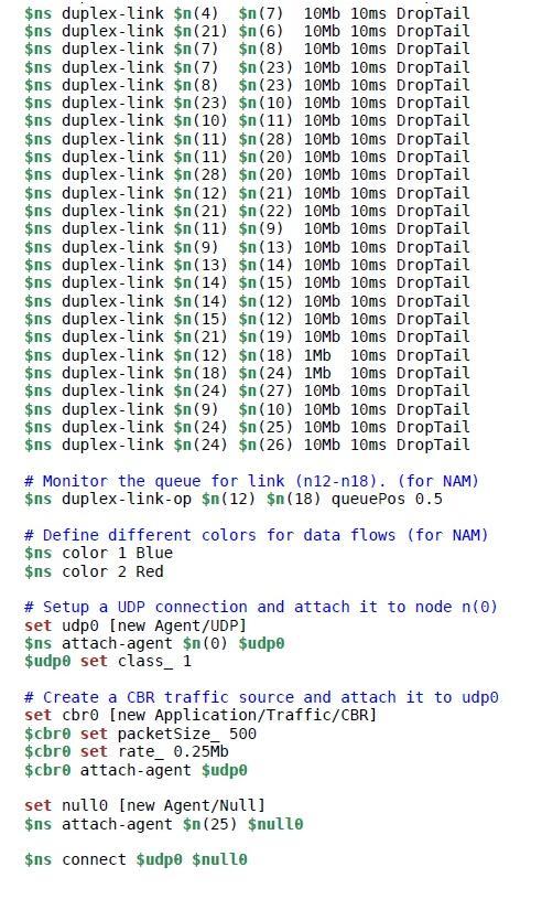
27 The algorithm is implemented in a simulated wired network shown in Figure 12. The network consists of 29 nodes interconnected to each other. The node 0 is the source of packets and node 25 is the destination in the simulation. This network deploys dynamic routing, resembling to a real time network. Every intermediate node between the source and destination acts as a router. The code for the network in Figure 12 and the simulation is shown in Appendix B. Every node in the simulated network showed in Figure 12 implements the packet marking algorithm. A node upon receiving a packet executes the piece of code shown in Appendix C, before forwarding the packet to the next node on the path. The packet marking algorithm is embedded into the simulator, such that all the nodes in the simulated network execute the packet marking technique. The simulation can be started by the user by clicking the play button in the network animator interface shown in Figure 12. Once the simulation starts, the source node 0 starts sending the packets to the destination node 25 based on the time event set in the simulation code. The flow of packets from source to destination is shown in blue color. 4.3 Traceback mechanism The receiver can trace the path to the source with the help of markings on the packets. Here as the algorithm is implemented into a simulation, all the simulation data is recorded into a trace file. An analysis of the trace file helps to construct the path to the source. Figure 13 shows filtered trace data with unique packet markings for the network shown in Figure 12. It is seen in Figure 13 that each unique packet marking has a unique Marked Hop Count (MHC), which represents the hop distance between the router that has marked the packet and the destination. 21
.")
28 Figure 13: Trace file with unique markings The packet marking data and the Marked Hop Count (MHC) data in Figure 13 is tabulated in Table 1 in increasing order of the Marked Hop Count (MHC). Table 1: Trace data for IP traceback 22
29 Table 1 represents data from both marked and unmarked packet data in an organized way. It is observed from the data in Table 1 that the packet with packet ID 665 was not marked by any of the intermediate routers and it shows the original TTL value assigned to the packet by the source, i.e., MRK = -1 and MHC = 32. From the current TTL value 20 and MHC = 32 at the destination node, it is understood that the source is 12 hops away from the destination. Finally substantial information is available to construct the path to the source shown in Figure 14. Figure 14: IP traceback to the source In order to test the efficiency of the Hop-based packet marking algorithm simulations were conducted considering various threshold values and different number of hops between the source and the destination. The results for these simulations are discussed in the section Application in the case of attacks The rise of attacks is growing exponentially. IP traceback is a successful technique to find the source of the attacks and determine the path travelled by the packets to perform the attack. This technique can be used in such scenarios to find the source of the attacks and the path taken by the packets from the attacker to the victim. 23

30 Figure 15: Simulated network under attack in NS-2 Consider a simulated network shown in Figure 15 with node 0 as the source and node 25 as the destination. Assume node 19 plays the role of an attacker. At a point of time stated in the simulation script the attacker node 19 performs a Denial of Service (DoS) attack by flooding the network with unwanted packets. The flow of packets sent by the attacker is shown in red color. It can be observed in the simulation that the packets sent from node 0 hardly reach the destination node 25, and most of them are dropped from the network which can be observed in Figure 15. This interrupts the communication between the source node 0 and destination node 25. The node 25 becomes the victim of the DoS attack. In such attack scenarios IP traceback technique can be used to find the source of attacks. 24
31 5. Results The following simulations are conducted to provide the justification for the considered threshold value of 25 in this project. The results prove that the threshold value of 25 generates efficient results using the Hop-based packet marking technique. The simulations conducted are Simulation 1: To demonstrate the effectiveness of the threshold value 25 and also to find the minimum number of packets required to trace the source for different threshold values with varying number of hop distances between the source and the destination Simulation 2: To find the average number of packets required for various threshold values on the network shown in Figure 12. Simulation 3: To find the marking probabilities of the intermediate routers between the source and the destination on the network shown in Figure 12, with the threshold value of Simulation 1 The purpose of this simulation is to find the minimum number of packets required to trace the source of the packets on a linear network consisting of hops 10, 15, 20 and 25 between the source and destination. The simulation was conducted with threshold values 10, 15, 20 and 25. A linear network consisting of 10 hops between the source and destination is shown in Figure 16. The results obtained from this simulation are tabulated in Table 2. 25

32 Figure 16: A simulated network with 10 hops Table 2: Threshold value vs Hop distance 26
33 From the results tabulated in Table 2, it is observed that the minimum number of packets required for hop distances greater than the threshold value is leading towards infinity. In spite of sending large number of packets, traceback was not possible for the hop distances greater than the threshold value. As discussed earlier that most of the packets on internet reach the destination within 25 hops. The same can be observed in Table 2, where for a threshold value of 25 the minimum number of packets required for hop distances 10, 15, 20, 25 are obtained without any hassles. The data in Table 2 is represented in the form of a graph in Figure 17. It can be observed from the graph the required number of packets increases as the threshold value increases for the same number of hops. It is also observed that a threshold value satisfies the traceback for the hop distance between the source and destination is less than or equal to the threshold value. Figure 17: Threshold value vs Hop distance 27

34 5.2 Simulation 2 The purpose of this simulation is to find the average number of packets required for a successful traceback to the source for threshold values 10, 15, 20 and 25. This simulation was conducted on the network shown in Figure 12. This simulation also shows the packet marking efficiency of the Hop-based packet marking algorithm. The number of packets sent from source to destination in this simulation is 25, 50, 60, 75 and 100. The results obtained from this simulation are tabulated in Table 3. Table 3: IP traceback vs Threshold value From the results in Table 3, it is seen that traceback is possible for different set of packets with threshold values of 15, 20 and 25 using the Hop-based packet marking algorithm. It can also be observed from the results in Table 3 that on an average about 65-75% of the packets received at the destination are marked. This proves the marking efficiency of the algorithm. The traceback 28
35 is possible for an average minimum number of packets 60 for threshold values 20 and 25. This also supports the consideration of the threshold value 25 for the Hop-Based packet marking algorithm, resulting in positive results. The tabulated results in Table 3 are represented in the form of a graph in Figure 18. As seen in the graph in Figure 18 it is observed that on an average about 65-75% of the packet flow sent is marked for the threshold values 10, 15, 20 and 25. This rate of marking is seen constant for different set of packets 25, 50, 60, 75 and 100. Figure 18: Marking probability vs Threshold value 5.3 Simulation 3 The purpose of this simulation is to find the marking probabilities of the intermediate nodes between the source and the destination. This simulation is carried out on the network shown in Figure 12 with the optimum threshold value 25 obtained from Simulation 1 and 29
36 Simulation 2. In this simulation about 250 packets are sent from the source to the destination. The number of packets marked by each of the intermediate nodes is tabulated in Table 4. The results data in Table 4 indicate that about 67% of the packets are marked. It can also be observed that the edge routers of the source are marking high probability of packets compared to the other routers in the path. This even helps the victim to find the source easily in the case of attacks, as the results are narrowing down directly to the edge routers of the source. Table 4: Number of packets marked by the intermediate nodes The tabulated results in Table 4 are represented in the form of a graph in Figure 19. It is also observed from the graph that the edge routers mark large amount of packets, which helps to track the source easily. This also supports the intention of the algorithm to not overwrite the markings on the packets. 30

37 Figure 19: Packets marked by intermediate routers 31
38 6. Conclusion and Future work The rise of Denial of Service (DoS) and Distributed Denial of Service (DDoS) attacks on the internet are growing rapidly causing troubles to the network and also decreasing the network performance. IP traceback is a method to traceback to the source of the packets. Packet marking schemes are the most successful implementation towards preventing DoS attacks by tracing to the source of attacks. Most of the existing packet marking techniques requires huge number of packets to traceback the source. They also have drawbacks such as router overhead, packet header overload, network overhead, etc. The aim of this project is to reduce the number of packets involved across the efficient traceback using Hop-based packet marking technique. The algorithm was implemented on a simulated wired network in NS-2. This algorithm has shown results with efficient marking of packets. It marks on an average of about 65-75% of the packet flow. The algorithm has also shown that the edge routers mark large number of packets than other routers on the path, thus helping to trace the source easily. The results obtained show that this algorithm requires less number of packets to traceback to the source of attacks, compared to the existing techniques. Though the receiver receives duplicate marking data of the intermediate routers, it requires only unique marking data per router to perform successful traceback. This indicates that the receiver requires packets marked with unique data equal to the number of intermediate routers between the source and the destination. The algorithm can be enhanced in terms of security constraints, such that an attacker cannot modify any marked information on the packet. Storing the 32-bit address of a router may sometimes overload the packet header, which can be enhanced using special encoding 32
39 techniques. This algorithm was tested on a wired network, which can be extended to wireless networks, mobile networks, etc. An IPv4 packet was taken into consideration in this simulation. The algorithm should be extended to IPv6 packet, as today IPv6 is widely in use. If an intermediate router can identify the flow of packets from source to destination and mark only a single packet from the flow, then the total number of packets required by the receiver will be reduced as well as the overall work load of the network reduces, improving network performance. Another key point to be considered for the future work is, if the attackers play the role of intermediate routers, what number of packets would be required by the receiver to traceback successfully. 33
40 7. References [Khan, 2011] Rizwan Khan. (2011), Detection and Control of DDOS Attacks over Reputation and Score Based MANET, Journal of Emerging Trends in Computing and Information Sciences. 2 (11), p9-12. [Rui, 2006] SU Pu-Rui (2006), Notes on Packet Marking for IP Traceback, Journal of Software. 12 (1), p7-13. [Perrig, 2005] Adrian Perrig (2005), FIT: Fast Internet Traceback Available: Last accessed: March 25, 2012 [Saurabh, 2012] Saurabh, S.; Sairam, A.S.;, "Linear and Remainder Packet Marking for fast IP traceback," Communication Systems and Networks (COMSNETS), 2012 Fourth International Conference on, vol., no., pp.1-8, 3-7 Jan [Savage, 2001] Savage, S.; Wetherall, D.; Karlin, A.; Anderson, T.;, "Network support for IP traceback," Networking, IEEE/ACM Transactions on, vol.9, no.3, pp , Jun 2001 [Bellovin, 2006] Steven M. Bellovin (2006), A Clean-Slate Design for the Next-Generation Secure Internet, Available: Last accessed: March 25, 2012 [Song, 2001] Dawn Xiaodong Song. (2001), Advanced and Authenticated Marking Schemes for IP Traceback 34
41 Available: Last accessed: March 25, 2012 [Simulator] Network Simulator 2 Available: Last accessed: June 5, 2012 [Ansari, 2003] Belenky, A.; Ansari, N.;, "IP traceback with deterministic packet marking," Communications Letters, IEEE, vol.7, no.4, pp , April 2003 [Doss, 2006] Alwis, H.A.; Doss, R.C.; Chowdhury, M.U.; Hewage, P.S.;, "A performance evaluation of Route Based Packet Marking (RBPM) for IP trace back," Multitopic Conference, INMIC '06. IEEE, vol., no., pp , Dec [Teerawat] Teerawat Issariyakul, Ekram Hossain, Introduction to Network Simulator NS2, Oct 2008 [NS Manual] The ns Manual Available: Last Accessed: June 5, 2012 [Marc Greis] Marc Greis s tutorial Available: Last Accessed: June 5, 2012 [David, 2011] David Chinnery, Ben Horowitz, A Network Hub Architecture in 2011 Available: Last Accessed: June 5,

42 Appendix A On an average most of the packets take atmost 25 hops on a network to reach the destination. A test was conducted to verify this value using tracert command on windows command prompt. The result of this test can be seen in Figure 20, Figure 21, Figure 22 and Figure 23. In this test the number of hops taken for a packet to travel to various web servers across the world is obtained. 20. It took 11 hops for a packet to reach Google s server located in Dallas, shown in Figure Figure 20: Trace route to Google 36


43 It took 18 hops for a packet to reach Japan National Tourism Organization s server which is located in Japan, shown in Figure 21. Figure 21: Trace route to Japan National Tourism Organization Figure 22. It took 22 hops for a packet to reach Incredible India s server located in India, shown in Figure 22: Trace route to Incredible India 37

44 It took 24 hops for a packet to France Guide s server located in France, shown in Figure 23. Figure 23: Trace route to France Guide Based on the results from Figure 20, Figure 21, Figure 22 and Figure 23 it is deduced that on an average a packet takes about 20 hops to reach the destination. It takes at most 25 hops in certain cases. 38

45 Appendix B 39
46 40

47 41
48 Appendix C 42
INTERNATIONAL JOURNAL OF COMPUTER ENGINEERING & TECHNOLOGY (IJCET)
") INTERNATIONAL JOURNAL OF COMPUTER ENGINEERING & TECHNOLOGY (IJCET) Proceedings of the 2 nd International Conference on Current Trends in Engineering and Management ICCTEM -2014 ISSN 0976 6367(Print) ISSN
INTERNATIONAL JOURNAL OF COMPUTER ENGINEERING & TECHNOLOGY (IJCET) Proceedings of the 2 nd International Conference on Current Trends in Engineering and Management ICCTEM -2014 ISSN 0976 6367(Print) ISSN
Discriminating DDoS Attacks from Flash Crowds in IPv6 networks using Entropy Variations and Sibson distance metric
 Discriminating DDoS Attacks from Flash Crowds in IPv6 networks using Entropy Variations and Sibson distance metric HeyShanthiniPandiyaKumari.S 1, Rajitha Nair.P 2 1 (Department of Computer Science &Engineering,
Prof. N. P. Karlekar Project Guide Dept. computer Sinhgad Institute of Technology
 Volume 4, Issue 7, July 2014 ISSN: 2277 128X International Journal of Advanced Research in Computer Science and Software Engineering Research Paper Available online at: www.ijarcsse.com Advance Deterministic
TRACEBACK OF DOS OVER AUTONOMOUS SYSTEMS
 TRACEBACK OF DOS OVER AUTONOMOUS SYSTEMS Mohammed Alenezi 1 and Martin J Reed 2 1 School of Computer Science and Electronic Engineering, University of Essex, UK mnmale@essex.ac.uk 2 School of Computer
DoS Attacks. Network Traceback. The Ultimate Goal. The Ultimate Goal. Overview of Traceback Ideas. Easy to launch. Hard to trace.
 DoS Attacks Network Traceback Eric Stone Easy to launch Hard to trace Zombie machines Fake header info The Ultimate Goal Stopping attacks at the source To stop an attack at its source, you need to know
A Survey on Different IP Traceback Techniques for finding The Location of Spoofers Amruta Kokate, Prof.Pramod Patil
 www.ijecs.in International Journal Of Engineering And Computer Science ISSN: 2319-7242 Volume 4 Issue 12 Dec 2015, Page No. 15132-15135 A Survey on Different IP Traceback Techniques for finding The Location
MITIGATION OF DENIAL OF SERVICE ATTACK USING ICMP BASED IP TRACKBACK. J. Gautam, M. Kasi Nivetha, S. Anitha Sri and P. Madasamy
 MITIGATION OF DENIAL OF SERVICE ATTACK USING ICMP BASED IP TRACKBACK J. Gautam, M. Kasi Nivetha, S. Anitha Sri and P. Madasamy Department of Information Technology, Velammal College of Engineering and
A hybrid IP Trace Back Scheme Using Integrate Packet logging with hash Table under Fixed Storage
 Available Online at www.ijcsmc.com International Journal of Computer Science and Mobile Computing A Monthly Journal of Computer Science and Information Technology IJCSMC, Vol. 2, Issue. 12, December 2013,
IP Traceback Based on Chinese Remainder Theorem
 IP Traceback Based on Chinese Remainder Theorem LIH-CHYAU WUU a, CHI-HSIANG HUNG b AND JYUN-YAN YANG a a Department of Computer Science and Information Engineering National Yunlin University of Science
Novel Hybrid Schemes Employing Packet Marking and Logging for IP Traceback. Basheer Al-Duwairi, Member, IEEE, and G. Manimaran, Member, IEEE
 1 Novel Hybrid Schemes Employing Packet Marking and Logging for IP Traceback Basheer Al-Duwairi, Member, IEEE, and G. Manimaran, Member, IEEE Abstract Tracing DoS attacks that employ source address spoofing
Geographical Division Traceback for Distributed Denial of Service
 Journal of Computer Science 8 (2): 216-221, 2012 ISSN 1549-3636 2012 Science Publications Geographical Division Traceback for Distributed Denial of Service 1 Viswanathan, A., 2 V.P. Arunachalam and 3 S.
DDOS Attack Prevention Technique in Cloud
 DDOS Attack Prevention Technique in Cloud Priyanka Dembla, Chander Diwaker CSE Department, U.I.E.T Kurukshetra University Kurukshetra, Haryana, India Email: priyankadembla05@gmail.com Abstract Cloud computing
Single Packet IP Traceback in AS-level Partial Deployment Scenario
 Single Packet IP Traceback in AS-level Partial Deployment Scenario Chao Gong, Trinh Le, Turgay Korkmaz, Kamil Sarac Department of Computer Science, University of Texas at San Antonio 69 North Loop 64 West,
Survey of Several IP Traceback Mechanisms and Path Reconstruction
 Available online at www.worldscientificnews.com WSN 40 (2016) 12-22 EISSN 2392-2192 Survey of Several IP Traceback Mechanisms and Path Reconstruction Dr. M. Newlin Rajkumar 1,a, R. Amsarani 2,b, M. U.
Spoofer Location Detection Using Passive Ip Trace back
 Spoofer Location Detection Using Passive Ip Trace back 1. PALDE SUDHA JYOTHI 2. ARAVA NAGASRI 1.Pg Scholar, Department Of ECE, Annamacharya Institute Of Technology And Sciences,Piglipur, Batasingaram(V),
International Journal of Scientific & Engineering Research, Volume 7, Issue 12, December ISSN
 International Journal of Scientific & Engineering Research, Volume 7, Issue 12, December-2016 360 A Review: Denial of Service and Distributed Denial of Service attack Sandeep Kaur Department of Computer
Prof. Shervin Shirmohammadi SITE, University of Ottawa. Internet Protocol (IP) Lecture 2: Prof. Shervin Shirmohammadi CEG
 Lecture 2: Prof. Shervin Shirmohammadi CEG") Lecture 2: Internet Protocol (IP) Prof. Shervin Shirmohammadi SITE, University of Ottawa Prof. Shervin Shirmohammadi CEG 4185 2-1 Network Layer Provides the upper layers with independence from the data
Lecture 2: Internet Protocol (IP) Prof. Shervin Shirmohammadi SITE, University of Ottawa Prof. Shervin Shirmohammadi CEG 4185 2-1 Network Layer Provides the upper layers with independence from the data
Enhancing Probabilistic Packet Marking by Integrating Dynamic Probability and Time to Live (TTL) Clustering
 Clustering") Available Online at www.ijcsmc.com International Journal of Computer Science and Mobile Computing A Monthly Journal of Computer Science and Information Technology IJCSMC, Vol. 3, Issue. 4, April 2014,
Available Online at www.ijcsmc.com International Journal of Computer Science and Mobile Computing A Monthly Journal of Computer Science and Information Technology IJCSMC, Vol. 3, Issue. 4, April 2014,
SIMULATION OF THE COMBINED METHOD
 SIMULATION OF THE COMBINED METHOD Ilya Levin 1 and Victor Yakovlev 2 1 The Department of Information Security of Systems, State University of Telecommunication, St.Petersburg, Russia lyowin@gmail.com 2
Various Anti IP Spoofing Techniques
 Various Anti IP Spoofing Techniques Sonal Patel, M.E Student, Department of CSE, Parul Institute of Engineering & Technology, Vadodara, India Vikas Jha, Assistant Professor, Department of CSE, Parul Institute
RETRIEVAL OF DATA IN DDoS ATTACKS BY TRACKING ATTACKERS USING NODE OPTIMIZATION TECHNIQUE
 RETRIEVAL OF DATA IN DDoS ATTACKS BY TRACKING ATTACKERS USING NODE OPTIMIZATION TECHNIQUE G.Sindhu AP/CSE Kalaivanicollege of technology *Mail-id:sindhugnsn24@gmail.com ABSTRACT: attempt derives from a
Performance Evaluation of MANET through NS2 Simulation
 International Journal of Electronic and Electrical Engineering. ISSN 0974-2174, Volume 7, Number 1 (2014), pp. 25-30 International Research Publication House http://www.irphouse.com Performance Evaluation
A Lightweight IP Traceback Mechanism on IPv6
 A Lightweight IP Traceback Mechanism on IPv6 Syed Obaid Amin, Myung Soo Kang, and Choong Seon Hong School of Electronics and Information, Kyung Hee University, 1 Seocheon, Giheung, Yongin, Gyeonggi, 449-701
An Enhanced Deterministic Flow Marking Technique to Efficiently Support Detection of Network Spoofing Attacks
 An Enhanced Deterministic Flow Marking Technique to Efficiently Support Detection of Network Spoofing Attacks Dang Van Tuyen 1, Truong Thu Huong 1, Nguyen Huu Thanh 1, Nguyen Tai Hung 1, Bart Puype 2,
IP traceback through (authenticated) deterministic flow marking: an empirical evaluation
 deterministic flow marking: an empirical evaluation") Aghaei-Foroushani and Zincir-Heywood EURASIP Journal on Information Security 2013, 2013:5 RESEARCH Open Access IP traceback through (authenticated) deterministic flow marking: an empirical evaluation Vahid
Aghaei-Foroushani and Zincir-Heywood EURASIP Journal on Information Security 2013, 2013:5 RESEARCH Open Access IP traceback through (authenticated) deterministic flow marking: an empirical evaluation Vahid
Comparative Study of IP Trace back Techniques
 Journal for Research Volume 02 Issue 02 April 2016 ISSN: 2395-7549 Comparative Study of IP Trace back Techniques Jigneshkumar V Madhad Department of Computer Engineering Narnarayan Shastri Institute of
Aparna Rani Dept. of Computer Network Engineering Poojya Doddappa Appa College of Engineering Kalaburagi, Karnataka, India
 Capturing the Origins of IP Spoofers Using Passive IP Traceback Aparna Rani Dept. of Computer Network Engineering Poojya Doddappa Appa College of Engineering Kalaburagi, Karnataka, India aparna.goura@gmail.com
SUMMERY, CONCLUSIONS AND FUTURE WORK
 Chapter - 6 SUMMERY, CONCLUSIONS AND FUTURE WORK The entire Research Work on On-Demand Routing in Multi-Hop Wireless Mobile Ad hoc Networks has been presented in simplified and easy-to-read form in six
A Probabilistic Packet Marking scheme with LT Code for IP Traceback
 A Probabilistic Packet Marking scheme with LT Code for IP Traceback Shih-Hao Peng, Kai-Di Chang, Jiann-Liang Chen, I-Long Lin, and Han-Chieh Chao Abstract Cybercrime has become an important issue in the
Enhancing the Reliability and Accuracy of Passive IP Traceback using Completion Condition
 Enhancing the Reliability and Accuracy of Passive IP Traceback using Completion Condition B.Abhilash Reddy 1, P.Gangadhara 2 M.Tech Student, Dept. of CSE, Shri Shiridi Sai Institute of Science and Engineering,
Introduction to Networks and the Internet
 Introduction to Networks and the Internet CMPE 80N Winter 2004 Lecture 18 Announcements Fourth quiz on Monday, March 1 st. Third HTML discussion session today by Kiran (before class). Summary posted on
Ref: A. Leon Garcia and I. Widjaja, Communication Networks, 2 nd Ed. McGraw Hill, 2006 Latest update of this lecture was on
 IP Version 4 (IPv4) Header (Continued) Identification (16 bits): One of the parameters of any network is the maximum transmission unit (MTU) parameter. This parameter specifies the maximum size of the
INTERNATIONAL JOURNAL OF PURE AND APPLIED RESEARCH IN ENGINEERING AND TECHNOLOGY
 Gayatri Chavan,, 2013; Volume 1(8): 832-841 T INTERNATIONAL JOURNAL OF PURE AND APPLIED RESEARCH IN ENGINEERING AND TECHNOLOGY A PATH FOR HORIZING YOUR INNOVATIVE WORK RECTIFIED PROBABILISTIC PACKET MARKING
A New Path for Reconstruction Based on Packet Logging & Marking Scheme
 A New Path for Reconstruction Based on Packet Logging & Marking Scheme K.Praveen Kumar. Asst Professor, Department of CSE, Mallineni Lakshmaiah Womens Engineering College Abstract Computer network attacks
COMP/ELEC 429/556 Introduction to Computer Networks
 COMP/ELEC 429/556 Introduction to Computer Networks Let s Build a Scalable Global Network - IP Some slides used with permissions from Edward W. Knightly, T. S. Eugene Ng, Ion Stoica, Hui Zhang T. S. Eugene
Performance Evaluation of Various Routing Protocols in MANET
 208 Performance Evaluation of Various Routing Protocols in MANET Jaya Jacob 1,V.Seethalakshmi 2 1 II MECS,Sri Shakthi Institute of Science and Technology, Coimbatore, India 2 Associate Professor-ECE, Sri
IP TRACEBACK Scenarios. By Tenali. Naga Mani & Jyosyula. Bala Savitha CSE Gudlavalleru Engineering College. GJCST-E Classification : C.2.
 Global Journal of Computer Science and Technology Network, Web & Security Volume 13 Issue 3 Version 1.0 Year 2013 Type: Double Blind Peer Reviewed International Research Journal Publisher: Global Journals
StackPi: New Packet Marking and Filtering Mechanisms for DDoS and IP Spoofing Defense
 1 StackPi: New Packet Marking and Filtering Mechanisms for DDoS and IP Spoofing Defense Abraham Yaar Adrian Perrig Dawn Song Carnegie Mellon University {ayaar, perrig, dawnsong }@cmu.edu Abstract Today
A NEW IP TRACEBACK SCHEME TO AVOID LAUNCH ATTACKS
 Available Online at www.ijcsmc.com International Journal of Computer Science and Mobile Computing A Monthly Journal of Computer Science and Information Technology IJCSMC, Vol. 3, Issue. 3, March 2014,
Identifying Spoofed Packets Origin using Hop Count Filtering and Defence Mechanisms against Spoofing Attacks
 Identifying Spoofed Packets Origin using Hop Count Filtering and Defence Mechanisms against Spoofing Attacks Israel Umana 1, Sornalakshmi Krishnan 2 1 M.Tech Student, Information Security and Cyber Forensic,
Distributed Denial-of-Service Attack Prevention using Route-Based Distributed Packet Filtering. Heejo Lee
 CERIAS Security Seminar Jan. 17, 2001 Distributed Denial-of-Service Attack Prevention using Route-Based Distributed Packet Filtering Heejo Lee heejo@cerias.purdue.edu Network Systems Lab and CERIAS This
Keywords MANET, DDoS, Floodingattack, Pdr.
 Volume 6, Issue 1, January 2016 ISSN: 2277 128X International Journal of Advanced Research in Computer Science and Software Engineering Research Paper Available online at: www.ijarcsse.com Detection and
A Stateless Traceback Technique for Identifying the Origin of Attacks from a Single Packet
 A Stateless Traceback Technique for Identifying the Origin of Attacks from a Single Packet Marcelo D. D. Moreira, Rafael P. Laufer, Natalia C. Fernandes, and Otto Carlos M. B. Duarte Universidade Federal
Performance Analysis of AODV Routing Protocol with and without Malicious Attack in Mobile Adhoc Networks
 , pp.63-70 http://dx.doi.org/10.14257/ijast.2015.82.06 Performance Analysis of AODV Routing Protocol with and without Malicious Attack in Mobile Adhoc Networks Kulbir Kaur Waraich 1 and Barinderpal Singh
Increasing the effectiveness of packet marking schemes using wrap-around counting Bloom filter
 SECURITY AND COMMUNICATION NETWORKS Security Comm. Networks 206; 9:3467 3482 Published online 7 July 206 in Wiley Online Library (wileyonlinelibrary.com)..554 RESEARCH ARTICLE Increasing the effectiveness
Flow Control Packet Marking Scheme: to identify the sources of Distributed Denial of Service Attacks
 Flow Control Packet Marking Scheme: to identify the sources of Distributed Denial of Service Attacks A.Chitkala, K.S. Vijaya Lakshmi VRSE College,India. ABSTRACT-Flow Control Packet Marking Scheme is a
A Network Coding Approach to IP Traceback
 A Network Coding Approach to IP Traceback Pegah Sattari, Minas Gjoka, Athina Markopoulou University of California, Irvine {psattari, mgjoka, athina}@uci.edu Abstract Traceback schemes aim at identifying
Single Packet ICMP Traceback Technique using Router Interface
 JOURNAL OF INFORMATION SCIENCE AND ENGINEERING 30, 1673-1694 (2014) Single Packet ICMP Traceback Technique using Router Interface Department of Computer Science and Engineering Thiagarajar College of Engineering
STF-DM: A Sparsely Tagged Fragmentation with Dynamic Marking an IP Traceback Approach. Online Publication
 STF-DM: A Sparsely Tagged Fragmentation with Dynamic Marking an IP Traceback Approach 1 Hasmukh Patel and 2 Devesh C. Jinwala 1 Gujarat Power Engineering and Research Institute, India 2 Sardar Vallabhbhai
Chapter 7 Internet Protocol Version 4 (IPv4) Kyung Hee University
 Kyung Hee University") Chapter 7 Internet Protocol Version 4 (IPv4) 1 7.1 Introduction The transmission mechanism used by the TCP/IP Unreliable and connectionless datagram protocol Best-effort delivery service IP packets can
Chapter 7 Internet Protocol Version 4 (IPv4) 1 7.1 Introduction The transmission mechanism used by the TCP/IP Unreliable and connectionless datagram protocol Best-effort delivery service IP packets can
Networking interview questions
 Networking interview questions What is LAN? LAN is a computer network that spans a relatively small area. Most LANs are confined to a single building or group of buildings. However, one LAN can be connected
A Secure Method to Deliver Access Tokens to End Hosts
 A Secure Method to Deliver Access Tokens to End Hosts Dr.V Asha 1, Ashwini M 2, Divyansh 3 1,2,3 Department of Master of Computer Applications, New Horizon College of Engineering, Abstract--IP traceback
IP Packet Switching. Goals of Todayʼs Lecture. Simple Network: Nodes and a Link. Connectivity Links and nodes Circuit switching Packet switching
 IP Packet Switching CS 375: Computer Networks Dr. Thomas C. Bressoud Goals of Todayʼs Lecture Connectivity Links and nodes Circuit switching Packet switching IP service model Best-effort packet delivery
Implementation of an Adaptive MAC Protocol in WSN using Network Simulator-2
 Implementation of an Adaptive MAC Protocol in WSN using Network Simulator-2 1 Suresh, 2 C.B.Vinutha, 3 Dr.M.Z Kurian 1 4 th Sem, M.Tech (Digital Electronics), SSIT, Tumkur 2 Lecturer, Dept.of E&C, SSIT,
Scalable Hash-based IP Traceback using Rate-limited Probabilistic Packet Marking
 TECHNICAL REPORT, COLLEGE OF COMPUTING, GEORGIA INSTITUTE OF TECHNOLOGY Scalable Hash-based IP Traceback using Rate-limited Probabilistic Packet Marking Minho Sung, Jason Chiang, and Jun (Jim) Xu Abstract
Foundations of Network and Computer Security
 Foundations of Network and Computer Security John Black Lecture #17 Oct 27 th 2005 CSCI 6268/TLEN 5831, Fall 2005 Backscatter Technique CAIDA (San Diego) owns large block of IP address space They have
On IPv6 Traceback. obaidgnetworking.khu.ac.kr,cshonggkhu.ac.kr. highlights the related works; Section 3 will give an overview
 On IPv6 Traceback Syed Obaid Amin, Choong Seon Hong Dept. Of Computer Engineering Kyung Hee University, South Korea obaidgnetworking.khu.ac.kr,cshonggkhu.ac.kr Abstract- The motivation of IP traceback
Efficient Hybrid Multicast Routing Protocol for Ad-Hoc Wireless Networks
 Efficient Hybrid Multicast Routing Protocol for Ad-Hoc Wireless Networks Jayanta Biswas and Mukti Barai and S. K. Nandy CAD Lab, Indian Institute of Science Bangalore, 56, India {jayanta@cadl, mbarai@cadl,
II. Principles of Computer Communications Network and Transport Layer
 II. Principles of Computer Communications Network and Transport Layer A. Internet Protocol (IP) IPv4 Header An IP datagram consists of a header part and a text part. The header has a 20-byte fixed part
Course 6. Internetworking Routing 1/33
 Course 6 Internetworking Routing 1/33 Routing The main function of the network layer is routing packets from the source machine to the destination machine. Along the way, at least one intermediate node
DENIAL OF SERVICE ATTACKS: PATH RECONSTRUCTION FOR IP TRACEBACK USING ADJUSTED PROBABILISTIC PACKET MARKING. A Thesis RAGHAV DUBE
 DENIAL OF SERVICE ATTACKS: PATH RECONSTRUCTION FOR IP TRACEBACK USING ADJUSTED PROBABILISTIC PACKET MARKING A Thesis by RAGHAV DUBE Submitted to the Office of Graduate Studies of Texas A&M University in
Lecture 13: Routing in multihop wireless networks. Mythili Vutukuru CS 653 Spring 2014 March 3, Monday
 Lecture 13: Routing in multihop wireless networks Mythili Vutukuru CS 653 Spring 2014 March 3, Monday Routing in multihop networks Figure out a path from source to destination. Basic techniques of routing
ICMP, ARP, RARP, IGMP
 Internet Layer Lehrstuhl für Informatik 4 Raw division into three tasks: Data transfer over a global network Route decision at the sub-nodes Control of the network or transmission status Routing Protocols
Routing Protocols in MANETs
 Chapter 4 Routing Protocols in MANETs 4.1 Introduction The main aim of any Ad Hoc network routing protocol is to meet the challenges of the dynamically changing topology and establish a correct and an
CIS 551 / TCOM 401 Computer and Network Security
 CIS 551 / TCOM 401 Computer and Network Security Spring 2008 Lecture 12 2/28/08 CIS/TCOM 551 1 Announcements Reminder: Project 2 is due Friday, March 7th at 11:59 pm 2/28/08 CIS/TCOM 551 2 Internet Protocol
An Efficient and Practical Defense Method Against DDoS Attack at the Source-End
 An Efficient and Practical Defense Method Against DDoS Attack at the Source-End Yanxiang He Wei Chen Bin Xiao Wenling Peng Computer School, The State Key Lab of Software Engineering Wuhan University, Wuhan
~~,~ Electrical ~, Computer ENGINEERING. Carnegie Melh m. StackPi: New Packet Marking and Filtering Mechanisms for DDoS and IP Spoofing Defense
 Carnegie Melh m StackPi: New Packet Marking and Filtering Mechanisms for DDoS and IP Spoofing Defense Abraham 2004 Yaar Advisor: Prof. Perrig ~~,~ Electrical ~, Computer ENGINEERING MS Project Report for
CHAPTER 4 SINGLE LAYER BLACK HOLE ATTACK DETECTION
 58 CHAPTER 4 SINGLE LAYER BLACK HOLE ATTACK DETECTION 4.1 INTRODUCTION TO SLBHAD The focus of this chapter is to detect and isolate Black Hole attack in the MANET (Khattak et al 2013). In order to do that,
POSSIBLE INTRUSIONS IP TRACE-BACK IN CLOUD COMPUTING ENVIRONMENT
 POSSIBLE INTRUSIONS IP TRACE-BACK IN CLOUD COMPUTING ENVIRONMENT Swapan Debbarma 1, Anupam Jamatia 2, Nikhil Debbarma 3, Kunal Chakma 4 Department of Computer Science and Engineering NIT, Agartala, India
IP Spoof Prevented Technique to Prevent IP Spoofed Attack
 Available ONLINE www.visualsoftindia.com/vsrd/vsrdindex.html VSRD-TNTJ, Vol. I (3), 2010, 173-177 S H O R T C O M M U N I C A T I O N IP Spoof Prevented Technique to Prevent IP Spoofed Attack 1 Rajiv Ranjan*,
Your projected and optimistically projected grades should be in the grade center soon o Projected: Your current weighted score /30 * 100
 You should worry if you are below this point Your projected and optimistically projected grades should be in the grade center soon o Projected: Your current weighted score /0 * 100 o Optimistic: (Your
A Novel Packet Marking Scheme for IP Traceback
 A Novel Packet Marking Scheme for IP Traceback Basheer Al-Duwairi and G. Manimaran Dependable Computing & Networking Laboratory Dept. of Electrical and Computer Engineering Iowa State University, Ames,
ANALYSIS AND EVALUATION OF DISTRIBUTED DENIAL OF SERVICE ATTACKS IDENTIFICATION METHODS
 ANALYSIS AND EVALUATION OF DISTRIBUTED DENIAL OF SERVICE ATTACKS IDENTIFICATION METHODS Saulius Grusnys, Ingrida Lagzdinyte Kaunas University of Technology, Department of Computer Networks, Studentu 50,
Analyze and Determine the IP Spoofing Attacks Using Stackpath Identification Marking and Filtering Mechanism
 Analyze and Determine the IP Spoofing Attacks Using Stackpath Identification Marking and Filtering Mechanism V. Shyamaladevi 1, Dr. R.S.D Wahidabanu 2 1 Research Scholar, K.S.Rangasamy College of Technology
Performance Analysis of Broadcast Based Mobile Adhoc Routing Protocols AODV and DSDV
 INTERNATIONAL JOURNAL OF COMPUTER SCIENCE AND MOBILE APPLICATIONS IJCSMA Performance Analysis of Broadcast Based Mobile Adhoc Routing Protocols AODV and DSDV Er. Sandeep Singh Khehra 1, Er. Abhinash Singla
1.1 SYMPTOMS OF DDoS ATTACK:
 2018 IJSRSET Volume 4 Issue 4 Print ISSN: 2395-1990 Online ISSN : 2394-4099 Themed Section : Engineering and Technology An Efficient Entropy Based Approach for the Detection of DDOS Attack Abhilash Singh,
Correlation Based Approach with a Sliding Window Model to Detect and Mitigate Ddos Attacks
 Journal of Computer Science Original Research Paper Correlation Based Approach with a Sliding Window Model to Detect and Mitigate Ddos Attacks 1 Ayyamuthukumar, D. and 2 S. Karthik 1 Department of CSE,
An Investigation about the Simulation of IP Traceback and Various IP Traceback Strategies
 IJCSNS International Journal of Computer Science and Network Security, VOL.8 No.12, December 2008 1 An Investigation about the Simulation of IP Traceback and Various IP Traceback Strategies S.Karthik 1
Design and Simulation Implementation of an Improved PPM Approach
 I.J. Wireless and Microwave Technologies, 2012, 6, 1-9 Published Online December 2012 in MECS (http://www.mecs-press.net) DOI: 10.5815/ijwmt.2012.06.01 Available online at http://www.mecs-press.net/ijwmt
Packet track and traceback mechanism against denial of service attacks
 September 2008, 15(3): 51 58 The Journal of China Universities of Posts and Telecommunications www.buptjournal.cn/xben Packet track and traceback mechanism against denial of service attacks LI Li, SHEN
IPv4 Lecture 10a. COMPSCI 726 Network Defence and Countermeasures. Muhammad Rizwan Asghar. August 14, 2017
 IPv4 Lecture 10a COMPSCI 726 Network Defence and Countermeasures Muhammad Rizwan Asghar August 14, 2017 Source of some slides: Princeton University Also thanks to J.F Kurose and K.W. Ross IPv4 Internet
Performance Evaluation of Mesh - Based Multicast Routing Protocols in MANET s
 Performance Evaluation of Mesh - Based Multicast Routing Protocols in MANET s M. Nagaratna Assistant Professor Dept. of CSE JNTUH, Hyderabad, India V. Kamakshi Prasad Prof & Additional Cont. of. Examinations
Firewalls and NAT. Firewalls. firewall isolates organization s internal net from larger Internet, allowing some packets to pass, blocking others.
 Firews and NAT 1 Firews By conventional definition, a firew is a partition made of fireproof material designed to prevent the spread of fire from one part of a building to another. firew isolates organization
Protecting DNS Critical Infrastructure Solution Overview. Radware Attack Mitigation System (AMS) - Whitepaper
 - Whitepaper") Protecting DNS Critical Infrastructure Solution Overview Radware Attack Mitigation System (AMS) - Whitepaper Table of Contents Introduction...3 DNS DDoS Attacks are Growing and Evolving...3 Challenges
Protecting DNS Critical Infrastructure Solution Overview Radware Attack Mitigation System (AMS) - Whitepaper Table of Contents Introduction...3 DNS DDoS Attacks are Growing and Evolving...3 Challenges
Detection of Spoofing Attacks Using Intrusive Filters For DDoS
 IJCSNS International Journal of Computer Science and Network Security, VOL.8 No.10, October 2008 339 Detection of Spoofing Attacks Using Intrusive Filters For DDoS V.Shyamaladevi Asst.Prof.Dept of IT KSRCT
EP2120 Internetworking/Internetteknik IK2218 Internets Protokoll och Principer
 EP2120 Internetworking/Internetteknik IK2218 Internets Protokoll och Principer Homework Assignment 1 (Solutions due 20:00, Mon., 10 Sept. 2018) (Review due 20:00, Wed., 12 Sept. 2018) 1. IPv4 Addressing
A REVIEW PAPER ON DETECTION AND PREVENTION OF WORMHOLE ATTACK IN WIRELESS SENSOR NETWORK
 A REVIEW PAPER ON DETECTION AND PREVENTION OF WORMHOLE ATTACK IN WIRELESS SENSOR NETWORK Parmar Amish 1, V.B. Vaghela 2 1 PG Scholar, Department of E&C, SPCE, Visnagar, Gujarat, (India) 2 Head of Department
interface Question 1. a) Applications nslookup/dig Web Application DNS SMTP HTTP layer SIP Transport layer OSPF ICMP IP Network layer
 Applications nslookup/dig Web Application DNS SMTP HTTP layer SIP Transport layer OSPF ICMP IP Network layer") TDTS06 Computer networks, August 23, 2008 Sketched answers to the written examination, provided by Juha Takkinen, IDA, juhta@ida.liu.se. ( Sketched means that you, in addition to the below answers, need
TDTS06 Computer networks, August 23, 2008 Sketched answers to the written examination, provided by Juha Takkinen, IDA, juhta@ida.liu.se. ( Sketched means that you, in addition to the below answers, need
(a) Which of these two conditions (high or low) is considered more serious? Justify your answer.
 Which of these two conditions (high or low) is considered more serious? Justify your answer.") CS140 Winter 2006 Final Exam Solutions (1) In class we talked about the link count in the inode of the Unix file system being incorrect after a crash. The reference count can either be either too high
CS140 Winter 2006 Final Exam Solutions (1) In class we talked about the link count in the inode of the Unix file system being incorrect after a crash. The reference count can either be either too high
TO DETECT AND RECOVER THE AUTHORIZED CLI- ENT BY USING ADAPTIVE ALGORITHM
 TO DETECT AND RECOVER THE AUTHORIZED CLI- ENT BY USING ADAPTIVE ALGORITHM Anburaj. S 1, Kavitha. M 2 1,2 Department of Information Technology, SRM University, Kancheepuram, India. anburaj88@gmail.com,
CSC 574 Computer and Network Security. TCP/IP Security
 CSC 574 Computer and Network Security TCP/IP Security Alexandros Kapravelos kapravelos@ncsu.edu (Derived from slides by Will Enck and Micah Sherr) Network Stack, yet again Application Transport Network
Multi Directional Geographical Traceback with n Directions Generalization
 Journal of Computer Science 4 (8): 646-651, 2008 ISS 1549-3636 2008 Science Publications Multi Directional Geographical Traceback with n Directions Generalization 1 S. Karthik, 2 V.P. Arunachalam and 3
Man in the middle. Bởi: Hung Tran
 Man in the middle Bởi: Hung Tran INTRODUCTION In today society people rely a lot on the Internet for studying, doing research and doing business. Internet becomes an integral part of modern life and many
Network Layer PREPARED BY AHMED ABDEL-RAOUF
 Network Layer PREPARED BY AHMED ABDEL-RAOUF Network layer transport segment from sending to receiving host on sending side encapsulates segments into datagrams on receiving side, delivers segments to transport
Performance Evaluation of Routing Protocols (AODV, DSDV and DSR) with Black Hole Attack
 with Black Hole Attack") Performance Evaluation of Routing Protocols (AODV, DSDV and DSR) with Black Hole Rozy Rana 1, Kanwal Preet Singh 2 1 Department of Computer Engineering, Master of Engineering, UCOE, Punjabi University
Performance Evaluation of Routing Protocols (AODV, DSDV and DSR) with Black Hole Rozy Rana 1, Kanwal Preet Singh 2 1 Department of Computer Engineering, Master of Engineering, UCOE, Punjabi University
ABSTRACT. are used to monitor physical and environmental conditions like temperature, pressure etc.
 ABSTRACT A Wireless Sensor Network (WSN) consists of autonomous sensor devices that are used to monitor physical and environmental conditions like temperature, pressure etc. The WSN is built of hundreds
Capability Analysis of Internet of Things (IoT) Devices in Botnets & Implications for Cyber Security Risk Assessment Processes (Part One)
 Devices in Botnets & Implications for Cyber Security Risk Assessment Processes (Part One)") Capability Analysis of Internet of Things (IoT) Devices in Botnets & Implications for Cyber Security Risk Assessment Processes (Part One) Presented by: Andrew Schmitt Theresa Chasar Mangaya Sivagnanam
Capability Analysis of Internet of Things (IoT) Devices in Botnets & Implications for Cyber Security Risk Assessment Processes (Part One) Presented by: Andrew Schmitt Theresa Chasar Mangaya Sivagnanam
International Journal of Intellectual Advancements and Research in Engineering Computations
 ISSN:2348-2079 Volume-6 Issue-2 International Journal of Intellectual Advancements and Research in Engineering Computations Local flow packet marking for network coding in manets P. Vasanthakumar, Mrs.
Markov Chain Modeling of the Probabilistic Packet Marking Algorithm
 Markov Chain Modeling of the Probabilistic Packet Marking Algorithm T.Y. Wong, John C.S. Lui, and M.H. Wong Department of Computer Science and Engineering The Chinese University of Hong Kong {tywong, cslui,
Tutorial 9. SOLUTION Since the number of supported interfaces is different for each subnet, this is a Variable- Length Subnet Masking (VLSM) problem.
 problem.") Tutorial 9 1 Router Architecture Consider a router with a switch fabric, 2 input ports (A and B) and 2 output ports (C and D). Suppose the switch fabric operates at 1.5 times the line speed. a. If, for
Tutorial 9 1 Router Architecture Consider a router with a switch fabric, 2 input ports (A and B) and 2 output ports (C and D). Suppose the switch fabric operates at 1.5 times the line speed. a. If, for