Radioline + EMpro Modbus communication
|
|
|
- Albert Haynes
- 6 years ago
- Views:
Transcription


1 Radioline + EMpro Modbus communication Wireless data transmission between EMpro and Radioline Quick Reference Guide QRG_605_EN_00_RAD-2400-IFS+EMpro-Modbus.docx PHOENIX CONTACT Pos. Quantity Order-No. Type Description RAD-2400-IFS 2400 MHz radio module with RS-232, RS wire interface RAD-CABLE-USB Configuration cable for RAD-2400-IFS EEM-MA EEM-MA EEM-RS485-MA EEM-MA EEM-ETH-RS485-MA600 Energy meter for measuring electrical parameters with RS-485 Modbus/RTU interface Energy meter for measuring electrical parameters, extendable with communication module Communication module, RS-485 Modbus, for EEM-MA400 Energy meter for measuring electrical parameters, extendable with communication module Communication module, gateway RS-485 / Ethernet, for EEM-MA600 This document is only valid in association with the associated user manuals or package slips. Make sure that you always use the latest documentation. It can be downloaded at
2 Contents 1 Configuration and connection of EMpro Preparing EMpro EEM-MA Connecting the devices Preparing EMpro EEM-MA Connecting the devices Preparing EMpro EEM-MA Modbus/RTU configuration Modbus/TCP configuration Connecting the devices Configuration of Radioline System setup Installation of the software Configuration of a point-to-point/star connection Read out the measured values via Modbus Poll software Reading the measured values (example: EMpro web server) Troubleshooting / FAQ QRG_605_EN_00_RAD-2400-IFS+EMpro-Modbus.docx PHOENIX CONTACT 2

3 The structure could look like this: Funkmodul RAD-2400-IFS Energiemessgerät EEM-MA400 Energiemessgerät EEM-MA250 Energiemessgerät EEM-MA600 This document describes the basic operation of a Modbus network comprising EMpro energy meters and Radioline devices. The EEM-MA600 with communication module EEM-ETH-RS485-MA600 operates as a gateway between Modbus/RTU and Modbus/TCP. The following chapters describe step-by-step the startup of EEM-MA250, EEM-MA400, EEM-MA600 and Radioline devices RAD-2400-IFS (Art. Nr ) with the Modbus Poll software on a Windows PC. The registers of each EMpro energy meter can be read out via Modbus Poll. QRG_605_EN_00_RAD-2400-IFS+EMpro-Modbus.docx PHOENIX CONTACT 3
.")
4 1 Configuration and connection of EMpro The EMpro measuring devices can be configured via the pushbuttons on the front side. The configuration is described in the following sections. 1.1 Preparing EMpro EEM-MA250 You will find the pin assignment of the power cable at Please enter the article number of EEM-MA250 ( ). The device can be configured via the pushbuttons on the front side. For changing the serial parameters of the EEM-MA250, push the PROG button for 3 seconds. Enter the code 100 to access the device configuration. Use the arrow keys to scroll through the menu and change the serial parameters. Note: - All Modbus devices must be set to the same serial parameters (data rate, etc.). - All Modbus devices must have different Modbus addresses. Configuration menu with adjustable serial parameters QRG_605_EN_00_RAD-2400-IFS+EMpro-Modbus.docx PHOENIX CONTACT 4

5 1.2 Connecting the devices The RS-485 interface must be connected as follows: EEM-MA250 RAD-2400-IFS Contact D(B) Contact D(A). The cable shield can be connected to an external cable shield ground clamp. Note: - EEM-MA250: The RS-485 cable must be terminated at both ends of the bus with a resistor. The resistor is supplied with the device. - RAD-2400-IFS: The resistor can be activated via DIP switches. QRG_605_EN_00_RAD-2400-IFS+EMpro-Modbus.docx PHOENIX CONTACT 5
6 1.3 Preparing EMpro EEM-MA400 You will find the pin assignment of the power cable at Please enter the article number of the EEM-MA400 ( ). The device can be configured via the pushbuttons on the front side. For changing the serial parameters of the EEM-MA400, push the PROG button for 3 seconds. Enter the Code 100 to access the device configuration. Use the arrow keys to scroll through the menu and change the serial parameters. Note: - All Modbus devices must be set to the same serial parameters (data rate, etc.). - All Modbus devices must have different Modbus addresses. Configuration menu with adjustable serial parameters, if communication module EEM-RS485-MA400 is connected. QRG_605_EN_00_RAD-2400-IFS+EMpro-Modbus.docx PHOENIX CONTACT 6
7 1.4 Connecting the devices The RS-485 interface must be connected as follows: EEM-MA400 RAD-2400-IFS Contact D(B) Contact D(A). The cable shield can be connected to an external cable shield ground clamp. RAD-2400-IFS EEM-RS485-MA Note: The RS-485 cable must be terminated at both ends of the bus with a resistor. The resistor can be activated via DIP switches. QRG_605_EN_00_RAD-2400-IFS+EMpro-Modbus.docx PHOENIX CONTACT 7
8 1.5 Preparing EMpro EEM-MA400 You will find the pin assignment of the power cable at Please enter the article number of the EEM-MA400 ( ). The device can be configured via the pushbuttons on the front side. For changing the serial parameters of the EEM-MA400, push the PROG button for 3 seconds. Enter the code 100 to access the device configuration. Use the arrow keys to scroll through the menu and change the serial parameters and Ethernet parameters. 1.6 Modbus/RTU configuration Note: - All Modbus devices must be set to the same serial parameters (data rate, etc.). - All Modbus devices must have different Modbus addresses. Configuration menu with adjustable serial parameters, if communication module EEM-ETH-RS485-MA600 is connected QRG_605_EN_00_RAD-2400-IFS+EMpro-Modbus.docx PHOENIX CONTACT 8
9 1.7 Modbus/TCP configuration Default settings: IP address: Subnet mask: Gateway: DHCP activation: No QRG_605_EN_00_RAD-2400-IFS+EMpro-Modbus.docx PHOENIX CONTACT 9
10 1.8 Connecting the devices The RS-485 interface must be connected as follows: EEM-MA600 RAD-2400-IFS Contact D(B) Contact D(A). The cable shield can be connected to an external cable shield ground clamp. RAD-2400-IFS EEM-ETH-RS485-MA Note: - The RS-485 cable must be terminated at both ends of the bus with a resistor. The resistor can be activated via DIP switches. - The EEM-ETH-MA600 allows for an Ethernet connection to 10BaseT or 100BaseT networks. Connect a twisted pair cable to the RJ45 connector of the communication module EEM-ETH-RS485-MA600 and connect it to your Ethernet network. QRG_605_EN_00_RAD-2400-IFS+EMpro-Modbus.docx PHOENIX CONTACT 10


11 2 Configuration of Radioline 2.1 System setup Point-to-Point Star Line/Mesh M = Master S = Slave R = Repeater Point-to-Point/Star A point-to-point/star network may consist of only one master and up to 249 slaves. In this network structure, each slave is directly connected to the master. The data exchange in this structure can be very fast. The more slaves are in the network, the higher is the delay time of the radio network. Line/Mesh A mesh network may consist of only one master and up to 249 slaves. A mesh network supports repeater functionality, it is able to heal itself. If a connection is lost, the device can establish an alternative communication path. This construction of an alternative communication path is done automatically within a very short time. This time depends on the data rate of the radio interface. The network type line/mesh results in a longer delay, because in this setting each wireless module works as a repeater/slave. The delay time depends on the number of repeaters/slaves in the network and of the selected data rate of the radio interface (16/125/250 kbaud). The Radioline devices support the following functions: Master: The master wireless module is the central point in the network. Initializations and network-specific functions are coordinated by the master. Without a master, there is no wireless connection in the network. The master of a wireless network is usually located at a central point, for example in the control room. The master PLC, which is connected to the master wireless module, manages the serial data transmission. There can only be one master in the network. The master always has the RAD-ID = 01. Slave: Slaves always build the endpoint of the network and cannot forward data to other slaves. Slaves of a PLC can be connected to a slave wireless module. Slave wireless modules only have subordinate rights. Repeater/Slave: A repeater/slave can communicate data to other wireless modules in the network. It is possible to build line/mesh structures. A repeater/slave supports two functions: The wireless module works as a repeater by receiving and forwarding data and as a slave by sending the data to its serial interface. A slave PLC can be connected to each repeater/slave wireless module. QRG_605_EN_00_RAD-2400-IFS+EMpro-Modbus.docx PHOENIX CONTACT 11

12 2.2 Installation of the software Please download the current PSI-CONF software at Install it on your computer and follow the instructions. 2.3 Configuration of a point-to-point/star connection 1. Start the PSI-CONF software on the PC. Connect the wireless module to the PC using the configuration cable. QRG_605_EN_00_RAD-2400-IFS+EMpro-Modbus.docx PHOENIX CONTACT 12


13 2. Select the device in the folder Wireless. 3. Select New by clicking on the button Create new network project. QRG_605_EN_00_RAD-2400-IFS+EMpro-Modbus.docx PHOENIX CONTACT 13


14 4. Step 1: Select the network type Point to Point / Star and confirm with Next. Note: Selecting the network type Line/Mesh results in a longer delay, as in this setting each wireless module works as a repeater/slave. The delay time depends on the number of repeaters/slaves in the network, the data package size and the selected data rate (16 / 125 / 250 kbaud). 5. Step 2: Follow the Wizard and select the number of network devices. Confirm with OK and Next. QRG_605_EN_00_RAD-2400-IFS+EMpro-Modbus.docx PHOENIX CONTACT 14

15 6. Step 3: Choose Serial data. Under Network settings, you can choose the RF channel, the network ID and the blacklisting of WLAN channels. Under Network speed/distance relation, you can choose the necessary data rate. The data rate depends on the distance. Confirm with Next. The Trusted Wireless 2.0 technology supports the following receiver sensitivity: Data transmission speed [kbps] Typical receiver sensitivity [dbm] Typical link budget [dbm] m m m * LOS = line of sight and adherence to the Fresnel zone Potential distance that can be covered with LOS* and a system reserve of 12 db You can achieve transmission within the kilometer range using the wireless module if the following conditions are fulfilled: - Suitable gain antennae are used - Line of sight - Adherence to the Fresnel zone QRG_605_EN_00_RAD-2400-IFS+EMpro-Modbus.docx PHOENIX CONTACT 15
.")
16 7. Step 4: Choose the connection profile PROFIBUS and select the required data rate. Confirm with Next. Note: - The serial data rate must be reduced depending on the distance to be covered (data rate of the radio interface 16/125/250 kbaud). - Set the same serial interface parameters as for the EMpro devices. QRG_605_EN_00_RAD-2400-IFS+EMpro-Modbus.docx PHOENIX CONTACT 16

17 8. Step 5: The configuration is finished. Confirm with Next. 9. Step 6: Save the project. QRG_605_EN_00_RAD-2400-IFS+EMpro-Modbus.docx PHOENIX CONTACT 17

18 Optimization for faster data transfer: 1. After saving, open Individual settings and change the value Transmissions to 1. Save the settings again and transfer the settings to the wireless devices. QRG_605_EN_00_RAD-2400-IFS+EMpro-Modbus.docx PHOENIX CONTACT 18
 and 20 dbm (100 mw). Depending on the place of installation and the antenna used, you may have to reduce the transmit power.")
19 Setting the transmit power 2. Open Individual Settings, Device Settings. Here you can set the transmit power and activate or deactivate the low noise amplifier. The Transmit Power can be set between 0 dbm (1 mw) and 20 dbm (100 mw). Depending on the place of installation and the antenna used, you may have to reduce the transmit power. Therefore, please note the restrictions of use according to your country and reduce the maximum power output of the device, if required. The Low Noise Amplifier can be enabled and disabled. It will change the sensitivity of the wireless module. For larger distances, the low noise amplifier must be activated. When wireless modules are operated in close proximity to each other (less than 1 meter), it is recommended to disable the low noise amplifier, so that the module is not overloaded. QRG_605_EN_00_RAD-2400-IFS+EMpro-Modbus.docx PHOENIX CONTACT 19

20 3 Read out the measured values via Modbus Poll software Modbus Poll is available as a free 30 day trial version on the following website: The software can read Modbus registers via different interfaces. 1. Install and run the software QRG_605_EN_00_RAD-2400-IFS+EMpro-Modbus.docx PHOENIX CONTACT 20

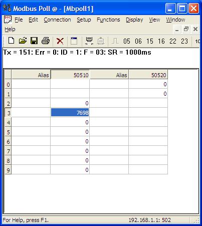
21 2. Choose Connection Connect to open the connection settings 3. Choose Modbus TCP/IP and enter the IP-Adresse of the EEM-MA600 / EEM-ETH-RS485-MA600 device. The standard Modbus port is preconfigured to Confirm with OK. The connection between EEM-MA600/EEM-ETH-RS485-MA600 and PC is established. The measured values of EEM-MA250 are displayed. QRG_605_EN_00_RAD-2400-IFS+EMpro-Modbus.docx PHOENIX CONTACT 21
 and register address 50512.")
22 5. Open Setup Read/Write Definition 6. Choose the Slave ID 1 (serial Modbus/RTU address of EEM-MA250) and register address QRG_605_EN_00_RAD-2400-IFS+EMpro-Modbus.docx PHOENIX CONTACT 22

23 The following spreadsheet (Manual EEM-MA250) shows the register addresses of the main measured values. QRG_605_EN_00_RAD-2400-IFS+EMpro-Modbus.docx PHOENIX CONTACT 23
24 . QRG_605_EN_00_RAD-2400-IFS+EMpro-Modbus.docx PHOENIX CONTACT 24

25 4 Reading the measured values (example: EMpro web server) Up to 10 slaves can be connected and evaluated via the web server interface. The integrated web server of the communication module connected to EEM-MA600 serves to configure, visualize and diagnose the devices in the network. The following functions are available via web server: Displaying the most important basic parameters of the EEM-MA600 Displaying the most important current and average measured values and counters Configuration, visualization and diagnostics of devices connected to the network To access the web server, you need to enter the IP address of the EEM-MA600 in the internet browser. Example: IP address of the energy meter EEM-MA600: You will find further information on the EMpro web server at QRG_605_EN_00_RAD-2400-IFS+EMpro-Modbus.docx PHOENIX CONTACT 25
26 5 Troubleshooting / FAQ Error: No network connection to EEM-MA600. ( Modbus Connection Failed. Connect Timeout im Modbus Poll) Reason: - EEM-MA600 cannot be reached. Correction: - Access the configuration menu and check the settings of the EEM-MA Check the IP address and subnet address of your PC Error: Gateway target device failed to respond im Modbus Poll (Tx and Err error counter count up) Reason: - Serial parameters of the RS-485 connection are wrong. - RS-485 interface not selected - Wiring inverted - Slave ID in Modbus Poll not correct Correction: - Check the serial settings and wiring on RAD-2400-IFS and EEM-MA250 - Check the slave ID in Modbus Poll Error: Illegal Data Value in Modbus Poll (Tx and Err error counter count up) Reason: Wrong main measurement value address in Modbus Poll Correction: Set the right register address via Read/Write Definition (see Modbus register tables of the EMpro device on page 23). PHOENIX CONTACT GmbH & Co. KG Blomberg Germany 26
Configuring RAD-900-IFS with GW MODBUS TCP/RTU for Modbus TCP I/O Emulation
 Configuring RAD-900-IFS with GW MODBUS TCP/RTU for Modbus TCP I/O Emulation Published: 2018-10-22 Contents Introduction... 1 Objectives:... 1 Requirements:... 2 Procedure... 3 Configuring the RAD-900-IFS
Configuring RAD-900-IFS with GW MODBUS TCP/RTU for Modbus TCP Communication
 Configuring RAD-900-IFS with GW MODBUS TCP/RTU for Modbus TCP Communication Published: 2018-10-22 Contents Introduction... 1 Objectives:... 1 Requirements:... 2 Procedure... 3 Configuring the RAD-900-IFS
SATEL-LP MHz wireless transceiver (transmitter and receiver) with RS-232 and RS-485 interface, can be extended with I/O extension modules
 with RS-232 and RS-485 interface, can be extended with I/O extension modules") 868 MHz wireless transceiver (transmitter and receiver) with RS-232 and RS-485 interface, can be extended with I/O extension modules Data sheet 106917_en_00 SATEL 2015-10-26 1 Description In addition to
868 MHz wireless transceiver (transmitter and receiver) with RS-232 and RS-485 interface, can be extended with I/O extension modules Data sheet 106917_en_00 SATEL 2015-10-26 1 Description In addition to
SATEL-LP product family
 SATEL-LP product family 24.11.2015 V1.6 SATEL LP -radio units SATEL-LP24 License free 2.4 GHz (2.4002 GHz... 2.4785 GHz) ISM (Industrial, Scientific and Medical) band, FHSS (Frequency Hopping Spread Spectrum)
RAD-DO8-IFS. I/O extension module, eight digital transistor outputs. Data sheet. 1 Description
 I/O extension module, eight digital transistor outputs Data sheet 105364_en_00 PHOENIX CONTACT 2013-03-26 1 Description The I/O extension module can be used in conjunction with Radioline wireless modules
3225_en_D Description
 3225_en_D 2014-01-21 1 Description 2 Table of contents 1 Description... 1 2 Table of contents... 2 3 Ordering data... 3 4 Technical data... 4 5 Safety regulations and installation notes... 6 5.1 Installation
MODEL CIO-EN MODBUS/TCP, MODBUS/RTU I/O MODULE
 INSTALLATION INSTRUCTIONS Revision B1 Rapid City, SD, USA, 05/2009 MODEL CIO-EN MODBUS/TCP, MODBUS/RTU I/O MODULE BE SURE POWER IS DISCONNECTED PRIOR TO INSTALLATION! FOLLOW NATIONAL, STATE AND LOCAL CODES.
RAD-DI8-IFS. I/O extension module with 8 digital inputs or 2 pulse inputs. INTERFACE Data sheet. 1 Description
 I/O extension module with 8 digital inputs or 2 pulse inputs INTERFACE Data sheet 0483_en_00 PHOENIX CONTACT 203-04-05 Description The I/O extension module can be used in conjunction with Radioline wireless
MODEL: GR8-EM. Communication Adaptor GR8 Series
 Communication Adaptor GR8 Series Ethernet/RS-485 Adaptor (Modbus use) Functions & Features Bidirectional protocol converter for Modbus/TCP (Ethernet) and Modbus RTU (RS-485) Fast response time thanks to
IL ETH BK DI8 DO4 2TX-PAC: IP ASSIGNMENT & WATCHDOG
 IL ETH BK DI8 DO4 2TX-PAC: IP ASSIGNMENT & WATCHDOG ILETHBKDI8DO42TX-PAC: IP Address Assignment With the "IP Assignment Tool" and Setting the Process Data Watchdog AUTOMATION Application Note 7621_en_00
Any device, including routers and hosts, is running an implementation of IP address Host
 INSTRUCTION MANUAL IM471-U v0.1 EMI-10L Introduction EMI-10L converter lets you convert a serial RS485 communications port on a bus Ethernet with TCP / IP. The concepts and terms commonly used in the TCP
Network planning tool for Phoenix Contact wireless products. User manual
 Network planning tool for Phoenix Contact wireless products User manual User manual Network planning tool for Phoenix Contact wireless products 2013-12-17 Revision: A This user manual is valid for: Designation
PB IL 24 BK DIO 16/16
 PROFIBUS-DP/V1 Bus Coupler Station With 16 Digital Inputs and 16 Digital Outputs Data Sheet 643701 07/2003 $ "! % * This data sheet is only valid in association with the "Configuring and Installing the
MODEL: WL40EW2F. Wireless I/O WL40F Series
 Wireless I/O WL40F Series WIRELESS GATEWAY Modbus/TCP (Ethernet), Modbus-RTU Transparent 900MHz Band Wireless Device (parent device) 60 (2.36) FUTIONS & FEATURES This unit Incorporates 900MHz band wireless
Dip Switch settings for 2-wire and 4-wire configuration. Schneider Electric - Division - Name Date
 Dip Switch settings for 2-wire and 4-wire configuration 1 2.0 Modbus Communication Cable Connection: Use cable wiring as shown in drawing below. Communication Protocol RS422 4-wire Communication port at
iopro Mirrored IO System
 Ph: (877) 343-8467 Fax: (800) 303-5381 Email: info@ioselect.com iopro Mirrored IO System Quick Start Guide (Ver. 6) www.ioselect.com Page 1 Introduction This document will cover how to use the iopro family
RAD-DOR4-IFS. I/O extension module, 4 digital relay outputs. INTERFACE Data sheet. 1 Description
 I/O extension module, 4 digital relay outputs INTERFACE Data sheet 104834_en_01 PHOENIX CONTACT 2013-01-21 1 Description The RAD-DOR4-IFS I/O extension module can be used in conjunction with Radioline
INDUSTRIAL ETHERNET MODULE TBOX Manual
 INDUSTRIAL ETHERNET MODULE TBOX Manual XINJE ELEC. CO., LTD CONTECTS 1 INTRODUCTION...1 2 COM PORT AND DISPLAY......3 3 PARAMETER SETTING...8 1 INTRODUCTION 1. Brief introduction Modbus protocol is industrial
Momentum 171 CCC Processor with Ethernet Communication Port
 Momentum 171 CCC 980 20 Processor with Ethernet Communication Port Description The Momentum model 171 CCC 980 20 Processor is a full capability programmable controller that includes integral Ethernet and
RAD-WHG/WLAN-XD. WirelessHART gateway with integrated WLAN (802.11b/g) INTERFACE Data Sheet 2720_en_C. 2 Features. 1 Description
 INTERFACE Data Sheet 2720_en_C. 2 Features. 1 Description") WirelessHART gateway with integrated WLAN (802.11b/g) INTERFACE Data Sheet 2720_en_C 1 Description PHOENIX CONTACT 2011-06-07 2 Features The RAD-WHG/WLAN-XD is a WirelessHART gateway with integrated 802.11b/g
WirelessHART gateway with integrated WLAN (802.11b/g) INTERFACE Data Sheet 2720_en_C 1 Description PHOENIX CONTACT 2011-06-07 2 Features The RAD-WHG/WLAN-XD is a WirelessHART gateway with integrated 802.11b/g
IntesisBox Modbus Server KNX
 IntesisBox Modbus Server KNX User Manual r1.0 eng Issue date: 09/2017 Intesis Software S.L.U. 2017 All Rights Reserved. Information in this document is subject to change without notice. The software described
Site Preparation. for AE250 Inverter Installation Guide. SolarVu
 5 Data 6 7 8 9 Site Preparation SolarVu for AE50 Inverter Installation Guide SolarVu is an energy portal that enables remote monitoring of renewable energy generation sites over the web. It requires the
Z-2400-RB/TCP TURBO Wireless Data Links Using ZIGBEE For MicroScan Protocols.
 Z-2400-RB/TCP TURBO Wireless Data Links Using ZIGBEE For MicroScan Protocols. Installation Guide. Z-2400-Base/Remote Turbo Installation Guide Index: Description. Page 3 Ordering Information. Page 3 Specifications.
Document Name: User Manual for SC10MK, Modbus RTU to Modbus TCP Converter
 Document Name: User Manual for SC10MK, Modbus RTU to Modbus TCP Converter Login for the first time, please use http://192.168.1.100 To key in user name and password is for identifying authorization. Default
VPGate Manual PROFIBUS to serial
 VPGate Manual PROFIBUS to serial Important information Purpose of the Manual This user manual provides information how to work with the VPGate PROFIBUS to serial. Document Updates You can obtain constantly
PSI-MODEM-SHDSL/SERIAL
 PSI-MODEM-/SERIAL -SERIAL permanent line modem Data sheet 104460_en_02 PHOENIX CONTACT 2011-12-06 1 Description The industrial SERIAL permanent line modem enables broadband networking of serial devices
isma-b-mg-ip User Manual Global Control 5 Sp. z o.o. Poland, Warsaw
 isma-b-mg-ip User Manual Global Control 5 Sp. z o.o. Poland, Warsaw www.gc5.pl Table of content 1 Introduction... 4 1.1 Revision history... 5 1.2 Safety rules... 5 1.3 Technical specifications... 6 1.4
Disclaimers. Important Notice
 Disclaimers Disclaimers Important Notice Copyright SolarEdge Inc. All rights reserved. No part of this document may be reproduced, stored in a retrieval system, or transmitted, in any form or by any means,
The TRSUN is the complete solution for the remote monitoring of photovoltaic plants.
 The TRSUN is the complete solution for the remote monitoring of photovoltaic plants. Monitoring of inverters and string combiner boxes (up to 64 devices); Complete configuration of the monitoring system
EdaFastCam The Smart Clip-on Meter Reader for Home and Business
 EdaFastCam The Smart Clip-on Meter Reader for Home and Business power of technology UNIVERSAL For all mechanical electricity, gas and water meters SIMPLE OCR-assisted install mechanism makes installation
FNL Modbus TCP Interface
 FNL Modbus TCP Interface Users Manual V0.1 17.06.2009 Project No.: 5304 Doc-ID.: FNL Modbus TCP Interface-UM-V0.1 Status: Released COMSOFT d:\windoc\icp\doku\hw\fnl\modbus tcp\version_0.1\fnl_modbus_tcp_e.doc
RAD XD and RAD XD-WM a/b/g Transceiver with Serial Link Quick Start Guide
 RAD-80211-XD and RAD-80211-XD-WM 802.11a/b/g Transceiver with Serial Link Quick Start Guide 1 This Quick Start Guide is intended to provide adequate information necessary to get a functional system operating.
P-Bus Quick Start. Revision History: Version Primary Authors Description of Version Date Approved. V1.0 A. K. Initial version
 P-Bus Quick Start Revision History: Version Primary Authors Description of Version Date Approved V1.0 A. K. Initial version 09.02.2010 Getting_Started_P-Bus_E1.doc 1/29 7/8/2010 Table of Contents 1 INTRODUCTION...
Example 1: Using Modbus Poll to MB-GATEWAY with DL06 Slave... A-2. Step 3: Connect to the MB-GATEWAY using the Modbus Poll simulator software...
 pplication Examples ppendix In this ppendix... Example 1: Using Modbus Poll to M-GTEWY with L0 Slave... - Items needed for this example:... - Step 1: onnect the M-GTEWY serial port to the L0 secondary
Quick Start. Appearance and pin assignments
 Quick Start WF-2055 Package Checklist The package includes the following items: One WF-2055 module One Quick Start One software utility CD One screw driver One RS-232 cable (CA-0910) One Antenna 2.4GHz
for AE 500NX Inverters Installation Guide COMMUNICATION SETTINGS (DEFAULT) SERIAL COMMS ADDRESS 22 8 RJ45 plug Viewed from pin side ORA-W ORA
 SERIAL COMMS ADDRESS 22 8 RJ45 plug Viewed from pin side ORA-W ORA") Site Preparation SolarVu for AE 500NX Inverters Installation Guide SolarVu is an energy portal that enables remote monitoring of renewable energy generation sites over the web. It requires the installation
Site Preparation SolarVu for AE 500NX Inverters Installation Guide SolarVu is an energy portal that enables remote monitoring of renewable energy generation sites over the web. It requires the installation
Dupline. Data Logger. Types G , G Product Description. Ordering Key G Type Selection. Input/Output Specifications
 Dupline Data Logger Types G 800 006, G 800 106 Product Description Programmable channel generator with optional built-in GSM Modem Event and time based data logging functions for digital, analog and counter
Ethernet Interface Module
 Interface Manual 1 Ethernet Interface Module SignalFire Number: ENET-DIN The SignalFire Ethernet Gateway has the following features: - Wide range DC power input. 6 to 36VDC - Power Over Ethernet (POE)
INSTALLATION GUIDE Maxiflex P3e CPU M1262F
 INSTALLATION GUIDE Maxiflex P3e CPU M1262F Introduction This Installation Guide is intended to aid the fitment of the M1262B CPU in the field. For operating details of this product, refer to the Users
IntesisBox Modbus Server Fidelio IP
 IntesisBox Modbus Server Fidelio IP User Manual r1 eng Issue Date: 10/04/2014 Intesis Software S.L. All Rights Reserved. Information in this document is subject to change without notice. The software described
Serial Connection of HC900 Hybrid Controller to 900CS Control Station
 Note: Ethernet connections will provide faster performance than RS-485 HC900 1. Remove HC900 CPU and set S2 Dip Switches for RS-485 unterminated Replace CPU & follow instructions per Installation and User
BMS-Ethernet-Gateway COM460IP
 BMS-Ethernet-Gateway TDB501015en / 11.2012 BMS-Ethernet-Gateway BMS-Ethernet-Gateway Device features Modular, expandable gateway between BMS bus and TCP/IP Gateway between BMS bus and Ethernet Range of
QUCM Limitorque Controller
 QUCM Limitorque Valve Controller Application Manual QUCM Limitorque Controller Installation and Programming Manual This Manual describes the QUCM application for interfacing Limitorque Valve Actuators
Anybus-CC CFW-11. User s Manual. Phone: Fax: Web: -
 Anybus-CC CFW-11 User s Manual Anybus-CC User s Manual Series: CFW-11 Language: English Document Number: 0899.5750 / 06 Publication Date: 09/2013 CONTENTS CONTENTS... 3 ABOUT THE MANUAL... 6 ABBREVIATIONS
Motortronics VirtualSCADA VS2-MT Communication Gateway VS2-MT User Manual Revision
 Motortronics VirtualSCADA VS2-MT Communication Gateway VS2-MT User Manual Revision 1.03.00 Motortronics / Phasetronics 1600 Sunshine Drive Clearwater, Florida 33765 Tel: 727-573-1819 Fax: 727-573-1803
IntesisBox Modbus Server M-Bus
 IntesisBox Modbus Server M-Bus User Manual r1.1 eng Issue date: 10/2017 Intesis Software S.L.U. 2017 All Rights Reserved. Information in this document is subject to change without notice. The software
SolarVu Installation Guide for Sungrow SG30KU Inverters
 SolarVu Installation Guide for Sungrow SG30KU Inverters Introduction SolarVu is an energy portal that enables remote monitoring of renewable energy generation sites over the internet. It requires the installation
PSI-MODEM-SHDSL/PB. Broadband PROFIBUS extender, SHDSL PROFIBUS leased line modem. Data sheet _en_03. 1 Description. 1.
 PSI-MODEM-/PB Broadband PROFIBUS extender, PROFIBUS leased line modem Data sheet 104396_en_03 1 Description PHOENIX CONTACT 2013-08-21 1.1 Features The PROFIBUS extender can be used to easily network PROFIBUS
HART/ Modbus TCP Gateway GT200-HT-MT User Manual V 1.2 REV A SST Automation
 HART/ Modbus TCP Gateway GT200-HT-MT User Manual V 1.2 REV A SST Automation E-mail: SUPPORT@SSTCOMM.COM WWW.SSTCOMM.COM Catalog 1 Product Overview... 4 1.1 Product Function...4 1.2 Product Features...
DeviceMaster UP Modbus Controller to Controller Communication
 DeviceMaster UP Modbus Controller to Controller Communication Today s Modbus installations are becoming increasingly complex. More and more installations are requiring the use of multiple Modbus controllers
Fieldgate SFG500. Technical Information. Intelligent Ethernet/PROFIBUS gateway
 Technical Information Fieldgate Intelligent Ethernet/PROFIBUS gateway Application Fieldgate is a system component that provides an independent access route to a PROFIBUS network. It may be used in a variety
COMTRAXX COM465DP. Condition Monitor with integrated gateway for the connection of Bender devices to PROFIBUS DP and Ethernet TCP/IP networks
 Condition Monitor with integrated gateway for the connection of Bender devices to PROFIBUS DP and Ethernet TCP/IP networks COM465DP_D00216_00_D_XXDE/10.2015 Condition Monitor with integrated gateway for
HRM-0800 Instruction Manual
 HRM-0800 Instruction Manual Table of Contents 1 Highway Addressable Remote Transducer (HART ) 4 2 General Specifications 5 3 Dimensions: 6 4 General Description 7 4.1 Introduction 7 4.2 Purpose 8 4.3 Functions
EtherSeries Modbus Gateway EMB-2 User s Guide
 EtherSeries Modbus Gateway EMB-2 User s Guide Revised March 25, 2004 Firmware Version 1.4 FCC Statement This device complies with the limits for a Class B digital device, pursuant to Part 15 of the FCC
SureCross DX80 Network Basics A Guide to SureCross Networks Table of Contents
 SureCross DX80 Network Basics A Guide to SureCross Networks Table of Contents Networking.... 3 Network Topologies.... 3 Banner s SureCross Wireless Network....4 Modbus RS-485.... 6 Modbus/TCP and EtherNet/IP
MOD-MUX MODBUS TCP I/O PRODUCTS
 MOD-MUX MODBUS TCP I/O PRODUCTS Catalog and Design Guide P.O.Box 24 Stanfield 3613 SOUTH AFRICA Tel: +27 (031) 7028033 Fax: +27 (031) 7028041 Email: proconel@proconel.com Web: www.proconel.com 22/09/2009
ICP DAS. ICP DAS 2015 M2M WLAN Wireless Solutions
 ICP DAS 2015 M2M WLAN Wireless Solutions Industrial Computer Industrial Product Data Computer Acquisition Product System Data Acquisition System PAC WLAN Wireless Solutions Wi-Fi Products WLAN Converter
Ethernet Network Card Installation and Operation Manual
 Ethernet Network Card Installation and Operation Manual Revision B 2017, Yaskawa - Solectria Solar Page 1 of 14 1. Overview 1.1 Introduction The Ethernet Network Card is used for monitoring and controlling
FAST EnergyCam. The Smart Clip-on Meter Reader for Home and Business
 FAST EnergyCam The Smart Clip-on Meter Reader for Home and Business FAST EnergyCam The Smart Clip-on Meter Reader for Home and Business FAST EnergyCam Smart metering power in a well designed and tiny package
---- IntesisBox KNX Modbus RTU Master and Modbus TCP Client
 ---- IntesisBox KNX Modbus RTU Master and Modbus TCP Client User Manual r1.1 eng Issue date: 05/2018 Intesis Software S.L.U. 2018 All Rights Reserved. Information in this document is subject to change
ICRM SER User s Guide
 ICRM- 915- SER User s Guide Introduction The ICRM- 915- SER is a high performance serial wireless modem designed to provide reliable long- range communications for SCADA systems. It is supplied in a compact
PWR. Power Module Slots
 INSTRUCTION MANUAL ETHERNET INTERFACE MODULE (Modbus/TCP) MODEL BEFORE USE... Thank you for choosing M-System. Before use, please check the contents of the package you received as outlined below. If you
HART / EtherNet/IP Gateway GT200-HT-EI User Manual V 1.0 REV A SST Automation
 HART / EtherNet/IP Gateway GT200-HT-EI V 1.0 REV A SST Automation E-mail: SUPPORT@SSTCOMM.COM WWW.SSTCOMM.COM Catalog 1 Product Overview... 4 1.1 Product Function...4 1.2 Product Features... 4 1.3 Technical
FAST EnergyCam. The Smart Clip-on Meter Reader for Home and Business
 The Smart Clip-on Meter Reader for Home and Business Retrofit rather than replace Smart metering power in a tiny, beautifully-designed package The quick and inexpensive way to turn your conventional meter
COMTRAXX COM465IP. Condition Monitor with integrated gateway for the connection of Bender devices to Ethernet TCP/IP networks
 Condition Monitor with integrated gateway for the connection of Bender devices to Ethernet TCP/IP networks COM465IP_D00217_00_D_XXDE/10.2015 Condition Monitor with integrated gateway for the connection
COMTRAXX COM465IP. Condition Monitor with integrated gateway for the connection of Bender devices to Ethernet TCP/IP networks
 Condition Monitor with integrated gateway for the connection of Bender devices to Ethernet TCP/IP networks COM465IP_D00217_04_D_XXEN/11.2018 Condition Monitor with integrated gateway for the connection
Version 1.0c May 6, 2010 ATK3
 Version 1.0c May 6, 2010 ATK3 Contents 1 Hardware 2 1.1 Inputs............................... 2 1.2 Outputs.............................. 3 1.3 RS485............................... 3 1.4 Ethernet..............................
- +-+ Fig 1 Internet Connection. SolarVu Server. Fig 2 K135 to Sunergy inverters serial connections
 SolarVu TM for Sustainable Energy Technologies Installation uide Site Preparation SolarVu TM is an energy portal that enables remote monitoring of renewable energy generation sites over the internet. It
BIET EtherNet Interface
 BIET EtherNet Interface Preliminary Release Notes are used to call attention to information that is significant to the understanding and operation of equipment. This BALOGH manual is based on information
HART Products. ICP Electronics Australia Pty Ltd Overview P 6-1
 Products 6.1 Overview P 6-1 Selection Guide - - - - - - - - - - - - - - - - - - - - - - - - - - - - - - - - - - - - - - - - - - - - - - - - - - - - - P 6-1 6.2 System Integration Solution P 6-2 6.3 Products
PROLOGIC Modular PLC CPU & I/O Modules Catalog and Design Guide
 PROLOGIC Modular PLC CPU & I/O Modules Catalog and Design Guide 23/03/2007 V0.1 Preliminary P.O.Box 24 Stanfield 3613 SOUTH AFRICA Tel: +27 (031) 7028033 Fax: +27 (031) 7028041 Email: proconel@proconel.com
GE Fanuc IC695ETM001. Rx3i PacSystem
 GE Fanuc IC695ETM001 http://www.pdfsupply.com/automation/ge-fanuc/rx3i-pacsystem/ic695etm001 Rx3i PacSystem Ethernet module 10/100 Mbits 2 RJ45 connections one IP address IC695E IC695ET IC695ETM 919-535-3180
AW58300HTP-PAIR USER S MANUAL
 USER S MANUAL 5.8 GHz Outdoor 300 Mbps Ethernet Point-to-Point Radio System Industrial-grade, long-range wireless Ethernet systems AvaLAN W I R E L E S S The AW58300HTP-PAIR consists of two AW58300HTS
R3-NE1 ETHERNET INTERFACE MODULE MODEL. Remote I/O R3 Series. (Modbus/TCP)
") Remote I/O R Series ETHERNET INTERFACE MODULE (Modbus/TCP) MODEL R-NE MODEL & SUFFIX CODE SELECTION R NE MODEL POWER INPUT K : V AC L : V AC R : V DC N : No power supply * *. Choose N (no power supply)
Remote I/O R Series ETHERNET INTERFACE MODULE (Modbus/TCP) MODEL R-NE MODEL & SUFFIX CODE SELECTION R NE MODEL POWER INPUT K : V AC L : V AC R : V DC N : No power supply * *. Choose N (no power supply)
MODBUS/TCP TO SIEMENS G110/G120/MM440 APPLICATION
 ICP PANEL-TEC MICROBRIDGE INSTALLATION AND OPERATION GUIDE MODBUS/TCP TO SIEMENS G110/G120/MM440 APPLICATION Revision History Revision Date Author Comments 000 02 June 2009 David Walker Initial release.
COMTRAXX COM460IP. BMS-Ethernet-Gateway
 COMTRAXX COM460IP BMS-Ethernet-Gateway COM460IP_D00023_03_D_XXEN/11.2015 COMTRAXX COM460IP BMS-Ethernet-Gateway COM460IP Device features Modular, expandable gateway between BMS bus and TCP/IP Gateway between
Installation and Programming Manual
 QUCM DF1 Application Manual QUCM DF1 Installation and Programming Manual This Manual describes the QUCM application for interfacing Allen-Bradley DF1 devices to a master of another protocol, including
Document Number: Rev. B
 User Guide Trademark Notices Microsoft and Windows are registered trademarks of Microsoft Corporation. Other product names mentioned herein may be trademarks and/or registered trademarks of their respective
PHOENIX CONTACT
 Fast connection connector for PROFIBUS systems Data sheet 101610_en_07 PHOENIX CTACT 2011-11-17 1 Description The D-SUB series SUBC-PLUS-PROFIB is specially designed for use in PROFIBUS systems up to 12
Do-more H2 Series PLC System Specifications
 Do-more H2 Series PLC System Specifications General Specifications General Specifications Operating Temperature 32 F to 131 F (0 C to 55 C) Storage Temperature 4 F to 158 F ( 20 C to 70 C) Ambient Humidity
Safety Instruction. This symbol indicates the possibility of injury or damage to property.
 ig5a Ethernet Option Manual Safety Instruction To prevent injury and danger in advance for safe and correct use of the product, be sure to follow the Safety Instructions. The instructions are divided as
XPress DR+W Quick Start Guide
 Industrial Device Server Quick Start Guide 2006 Copyright Lantronix is a trademark of Lantronix. All rights reserved. 900-446 Rev. A 10/06 XPRESS DR+W QUICK START CONTENTS What s In the Box..........................................................2
INTRODUCTION - DISPLAYS, DATA LOGGERS AND SOFTWARE
 INTRODUCTION - DISPLAYS, DATA LOGGERS AND SOFTWARE In times where energy conservation is a top priority for all progressive enterprises, the measurement of flow rates and consumption is becoming more and
E2 Ethernet Box-to-Box Setup: Quick Start
 TECHNICAL BULLETIN E2 Ethernet Box-to-Box Setup: Quick Start E2 Ethernet box-to-box communications allows two or more E2 controllers on an Ethernet network to share data. Communication between E2 controllers
User Manual Edition: v a
 WPC-832-Con 2 Ports Modbus TCP to Modbus RTU Wi-Fi, Ethernet connection Data Concentrator User Manual Edition: v.201809a http://www.tcpipweb.com Table of Contents Introduction------------------------------------------------------------------------------------------------------------------------------
User Manual of 5.8G Outdoor CPE
 User Manual of 5.8G Outdoor CPE Version V1.2 Thank you for purchasing Enterprise High Gain Outdoor CPE. This manual will instruct you how to configure and manage this CPE, enable you to use it in a perfect
SST-2450 Wireless Modem User s Manual
 SST-2450 Wireless Modem User s Manual Warranty All products manufactured by ICP DAS are warranted against defective materials for a period of one year from the date of delivery to the original purchaser.
PCAN-Gateway Quick Start Guide
 PCAN-Gateway Quick Start Guide Congratulations...... on your new PCAN-Gateway. This guide covers the basic configuration and operation of the PCAN-Gateway product family. Documentation Detailed documentation
INTRINSICALLY SAFE DUPLEXER PROTECTION. ELECTRONICS, INC Vulcan Road Apopka, Florida MOTOR INSTRUCTION MANUAL
 INTRINSICALLY SAFE DUPLEXER INSTRUCTION MANUAL MOTOR PROTECTION ELECTRONICS, INC. 2464 Vulcan Road Apopka, Florida 32703 Phone: Website: (407) 299-3825 www.mpelectronics.com Operating Program Revision:
Ethernet. Motion Control Products
 Ethernet Motion Control Products About the Class4 Ethernet SmartMotor Smartmotor -ETH Overview The -ETH option provides an Ethernet/RS485 converter to transfer ASCII data to the Smartmotor. Ethernet is
NetBiter I/O Extender User Manual
 User Manual Part no. 0920-9999-009 IntelliCom Innovation AB Pilefeltsgatan 73 SE-302 50 Halmstad SWEDEN Phone +46 35 17 29 90 Fax +46 35 17 29 09 email info@intellicom.se www www.intellicom.se Revision
Supplementary device manual AS-i controllere with Ethernet programming interface A AC1353 / AC1354 AC1355 / AC1356 AC1357 / AC1358
 Supplementary device manual AS-i controllere with Ethernet programming interface A AC1353 / AC1354 AC1355 / AC1356 AC1357 / AC1358 Firmware version RTS 2.x Target from V15 onwards for CoDeSys from version
MDC-211-ZT User Manual
 Warranty Warning MDC-211-ZT User Manual All products manufactured by ICP DAS are under warranty regarding defective materials for a period of one year, beginning from the date of delivery to the original
1 Access to the configuration page
 Index 1 Access to the configuration page... 4 2 IP address modification... 8 2.1 Ethernet... 8 2.2 WIFI (opzional)... 9 3 232-LAN/WLAN Configuration... 10 4 485-LAN/WLAN Configuration... 11 5 TCP/UDP Port
NETL ink gateways. Ethernet gateways WLAN gateways High-speed USB gateways
 NETL ink gateways Ethernet gateways WLAN gateways High-speed USB gateways ETHERNET NETL ink PRO PoE, PROFIBUS Ethernet gateway FEATURES RFC (ISO on TCP) CPU-to-CPU communication (with S-¹ and S-¹) (POE)
FIELDBUS OVERVIEW Graham Traill 02/09/2015
 FIELDBUS OVERVIEW Graham Traill 02/09/2015 What is Fieldbus? In its simplest form Fieldbus is a means of communicating with input devices (sensors, switches.) and output devices (valves, drives, indication
Universal Serial/PROFIBUS DP Gateway GT200-DP-RS User Manual V6.1 SST Automation
 GT200-DP-RS V6.1 SST Automation E-mail: SUPPORT@SSTCOMM.COM WWW.SSTCOMM.COM Catalog 1 About the Gateway...4 1.1 Product Function...4 1.2 Product Features... 4 1.3 Technical Specifications... 4 1.4 Related
This data sheet is only valid in association with the IL SYS INST UM E user manual.
 Inline analog input terminal, 4 inputs for connecting voltage signals Data sheet 8081_en_01_C01 PHOENIX CONTACT 2015-04-14 1 Description The terminal is designed for use within an Inline station. It is
IntesisBox Modbus Server Siemens Synova FC330A
 IntesisBox Modbus Server Siemens Synova FC330A User's Manual V10 r10 eng Intesis Software S.L. 2009. All Rights Reserved. Information in this document is subject to change without notice. The software
Netbiter EC300 Series
 Netbiter EC300 Series USER MANUAL SCM-1202-012 2.2 ENGLISH Important User Information Liability Every care has been taken in the preparation of this document. Please inform HMS Industrial Networks AB of