Ethernet Primer (v6.1)
|
|
|
- Imogen Jacobs
- 5 years ago
- Views:
Transcription

1 Page - 1
2 Page - 2

3 Basic ideas: Bus topology based on coax-cables with passive, uninterrupted coupling. Shared media like the Ether of air. Bidirectional signal-propagation -> termination resistors avoid signal reflections. Only half duplex transmission is possible. Control who is allowed to send is performed by media access control implementation. Given transmitting power of a network station limits cable length and number of receiverstations. 10 Mbit/s baseband transmission with Manchester encoding. To differentiate between network stations we need addresses -> source and destination MAC addresses. The initial idea of Ethernet was completely different than what is used today under the term "Ethernet". The original new concept of Ethernet was the use of a shared media and an Aloha based access algorithm, called Carrier Sense Multiple Access with Collision Detection (CSMA/CD). Coaxial cables were used as shared medium, allowing a simple coupling of station to bus-like topology. Coax-cables were used in baseband mode, thus allowing only unicast transmissions. Therefore, CSMA/ CD was used to let Ethernet operate under the events of frequent collisions. Another important point: No intermediate network devices should be used in order to keep latency as small as possible. Soon repeaters were invented to be the only exception for a while. A repeater is just a simple signal amplifier used to enlarge the network diameter according the repeater rules but there is not any kind of network segmentation -> it is still one collision domain! An Ethernet segment is a coax cable, probably extended by repeaters. The segment constitutes one collision domain (only one station may send at the same time) and one broadcast domain (any station receives the current frame sent). Therefore, the total bandwidth is shared by the number of devices attached to the segment. For example 10 devices attached means that each device can send 1 Mbit/s of data on average. Ethernet technologies at that time ( s): 10Base2 and 10Base5 Page - 3
 circuit.")
4 Ethernet is a shared media technology, so a procedure had to be found to control the access onto the physical media. This procedure was called the Carrier Sense Multiple Access Collision Detection (CSMA/CD) circuit. The way it works is quite simple, every stations that wants to send need to do a Carrier Sense to check if the media is already occupied or not. If the media is available the station is allowed to perform an Media Access and may start sending data. In the case that two stations almost at the same time access the media, a collision will happen. To recognize and resolve a collision is the task of the Collision Detect circuit. Every station listens to its own data while sending. In the case of a collision the currently sending stations recognize the collision by the superimposition of the electrical signals on the wire. Collisions are detected (CD) by observing the DC-level on the medium. A jamming signal will be sent out to make sure all involved stations recognize the occurrence of an collision. All stations involved in the collision stop sending and start a randomize timer. When the randomize timer expires the station may try to access the media again.. Page - 4
5 Collision Detection details: In coaxial Ethernet, transceivers send their Manchester code using the DC offset method. A "high" value is nominally zero current; a "low" value is nominally -80 ma. This results in a DC component to the signal of -40 ma, which creates a voltage of -1 VDC (the transceiver sees a 25 ohm load from the two 50 ohm cables going "left and right" away from the transceiver). When two transceivers send at the same time, their currents add, increasing the DC component of the combined signal to -2 VDC Thus, we can detect collisions by looking for DC signals in excess of the maximum that could possibly be generated by a single transmitter. Page - 5

6 In the worst case stations have to send bits twice the maximum signal propagation time (RTT) for reliable collision detection. Otherwise a collision may not be seen by the transmitting station for the currently transmitted frame. There is a very basic Ethernet rule that says a collision must be detected while a station is transmitting data. Therefore a stations needs to keep on sending at least of the duration of the RTT of the Ethernet system. If collisions occur after expiration of the slot time we talk about late collisions, which may cause malfunctions in the network. For example if a station transmits a frame and no collision was detected, the station assumes correct delivery of the frame. Now the station removes the frame from the transmit buffer, leaving no chance to retransmit the frame in the case of a late collision. The maximum allowed RTT is standardized and is called the slot time. The slot time for 10Mbit/ s Ethernet systems is set to 51,2 µs = 512 bit-times. Hence minimal Ethernet frame length is 64 byte. The request for fairness limits the maximum Ethernet frame size, too byte is the maximum allowed Ethernet frame size. With signal speed of 0.6c and the delay caused by electronic circuits such as interface cards and repeaters the slot time allows a maximum network diameter of 2500 meters for 10 Mbit/s. The maximum network diameter of faster Ethernet systems is directly related to their shorter slot times, because of the higher speed e.g. 250 meters for 100 Mbit/s (Fast Ethernet), 25 meters for 1000 Mbit/s (Gigabit Ethernet). These distance limitations must only be taken into account in shared media environments like Page - 6

7 Every station on a LAN is identified by a unique MAC-address which may be used either as source or destination MAC-address in LAN frames. A MAC address is 6 bytes or 48 bits long and is typically written in hexadecimal notation. The first two bits of a MAC address on the have a special meaning. The first bit (I/G) specifies whether the MAC address is a unicast address (0) or a broadcast/multicast address (1). A multicast is a broadcast for a group whereas broadcast addresses all stations on a single LAN. The broadcast-address is an address with all bits set to 1 (hex FFFF FFFF FFFF, U/L is set to 1). Please recognize that bit 47 (I/G) has no meaning in the source address of a LAN frame. The second bit (U/L) specifies whether it s a global and unique MAC address administered by the IEEE, or a local administered address. Page - 7

8 The MAC addresses are globally administered by the International Electrical and Electronic Engineering (IEEE) standardization organization. Each vendor of networking components can apply for an globally unique vendor code. The vendor code costs 1000$ and occupies the first three bytes of the MAC address. The remaining three bytes of the MAC address may be used by the vendor to address its components. Every Ethernet network card has one burnt in MAC address (BIA). Network cards of some vendors even support the use of programmable local administered MAC addresses. Page - 8
 through all other layers.")
9 Because the communication between different systems can be a very complex task, OSI splits the communication aspects into smaller tasks. All layering is based on the OSI reference Model, which defines tasks and interactions of seven layers. The user s data moves from the first layer (Application Layer) through all other layers. When two systems communicate with each other, then only the different layers talk. The application layer only talk with the application layer or the network layer only communicate with the network layer of system B. We can talk about a parallel communication between the layers. Every layer works for its own, it is not interested what the other layer does. Page - 9

10 One of the most important principles: Every layer adds its own protocol header by going downstairs in the stack -> Encapsulation at the source. Every layer removes its own protocol header by going upstairs in the stack -> Decapsulation at the destination. Page - 10
 of a station depending on its own BIA and the destination address of the received frame.")
11 Receipt of frames: Because of the inherent broadcast behavior of a LAN every frame is received by the Network Interface Card (NIC) of a station. The NIC decides if a frame should be forwarded to the higher layers (3-7) of a station depending on its own BIA and the destination address of the received frame. Usually NIC interrupts the CPU of the station if frame is to be forwarded. Otherwise the received frame is silently discarded by the NIC. Frame are only forwarded to the higher layers (3-7) : 1. The destination address of the frame is equal with own BIA address 2. The destination address was a broadcast address 3. The destination address was a multicast (group) address and the given station is member of such a group. The later two are seen on the next two slides. Page - 11
12 Keep in mind that for normal operation frames should be destined to a station specific MACaddresses (direct communication), because broadcast frames will interrupt all stations for further handling by the higher layers. Even if it turns out that a station needs not to act on such a broadcast frame the CPU time of this stations will be wasted. Broadcast should be used in initialization phases of a network only! Page - 12
13 In this example computer A and C are programmed to listen to group address X. Computer D will not be disturbed by this frame because it is not programmed to listen to X. Page - 13
 Maximum number of frames per second on a 10 Mbit/s Ethernet: 14880 frames of")
14 Some more Ethernet parameters: Interframe gap between to Ethernet frames is 9.6 microsecond. Jam size is 32 bit. Slot time is 512 bits, minimal frame length 64 Byte Maximal frame length 1518 byte ( ) Maximum number of frames per second on a 10 Mbit/s Ethernet: frames of minimal length ( , FCS counted, preamble not counted) Page - 14
 and SAPs -> the protocol-type is indicated by SSAP and DSAP and the LLC control field can provide connectionless and connection-oriented services to the upper layers.")
15 Remember IEEE relies on LLC (802.2) and SAPs -> the protocol-type is indicated by SSAP and DSAP and the LLC control field can provide connectionless and connection-oriented services to the upper layers. Ethernet Version 2 uses a protocol-type-field instead of the length field and lacks from any kind of HDLC like control field. Therefore only connectionless services can be provided by Ethernetv2 to the upper layers. Page - 15

16 So we end up with three different frame formats used in Ethernet systems. The / LLC without SNAP, the Ethernet v2 format and the 802.3/802.2 LLC with SNAP. The DIX Eth 2 frame format is mainly used for the data transport of protocols that have the functionality of error recovery and flow control implemented in their protocol stack e.g. IP. The 802.3/802.2 without SNAP frame format is used for protocols that need the functions of error recovery and flow control on layer 2 e.g. NetBeui, SNA. The 802.3/802.2 with SNAP frame format is used by vendors to implement proprietary protocols, for example Cisco's CDP, VTP, CGMP, etc. protocols. For such purposes the OUI field is used to indicate the vendor and the type field value is chosen vendor specific. Page - 16

17 Repeater is an amplifier expanding the maximal distance of an Ethernet-LAN segment. It regenerates signals on the receiving port, amplify them, and send these signals to all other connected net segments (no buffering, just a short delay, which must be taken into account for the collision window / slot-time). A repeater is an active network element which needs electrical power for its operation. In case a collisions is detected all other ports are notified by jam-signal. Optionally auto partition on erroneous ports may be performed by a repeater. Link segment: a physical point-to point connection between two devices Coax segment: the shared media as bus for network stations Local repeaters directly connect two (coax) segments. Remote repeaters are connected by so called linked segments which are point-to-point links between repeaters. First link segments were used for repeater interconnection only. Several types were defined (fiber based, copper based): FOIRL (Fibre Optic Inter Repeater Link: maximal length 1000m, for repeater - repeater) 10BaseFL (asynchronous, maximal length 2000m for repeater - repeater, end system - multiport repeater) 10BaseFB (synchronous (idle signals during communication pauses), maximal length 2000m, for repeater - repeater links only) 10BaseFP (passive hub, no active repeater function) Important: Collision domain is preserved by repeaters. A repeater with more than two segments and different physics is called a multiport repeater. Multiport repeater in a star like topology is called a Hub. Be careful using this expression because it is also used for L2 Ethernet-Switch which is a packet switch but not an amplifier like a repeater. Page - 17

18 The link segment was later also defined for connection of a network station (end system) to a multiport repeater using a dedicated physical point-to-point line. The reason: Ethernet was originally based on coax cabling and bus topology which was hard to wire in a building. Later an international standard for structured cabling of buildings was defined which was star wired to (a) central point(s) based on twisted pair cabling. Ethernet standard 10BaseT supporting structured cabling was created in order to reuse the voice-grade twisted-pair cables already installed in buildings. 10BaseT had been specified to support Cat3 cables (voice grade) or better, for example Cat4 (and today Cat5, Cat6, and Cat7). 10BaseT parameters: unshielded twisted pair, maximal length 100m, 2 lines Tmt+-, 2 lines Rcv+-, RJ45 connector, Manchester-Code with no DC offset Collision detection details: In such an environment the collisions can not be detected any longer just by measurement of the DC level as done in 10Base5 because tmt and rcv travels on different physical lines. Now a collision is interpreted, if signals are on the tmt and rcv line at the same time. The repeater has to watch out, if two or more signals are received at the same time (-> that means collision in the LAN). Now the hub has to produce a Jam signal on all ports in order to signal a collision to all systems. In 10BaseT, the Manchester code is sent symmetrically, with no DC offset. Collisions are detected in the repeater hub, which can observe when two or more devices are transmitting at the same time. Normally, the hub does not repeat a station's own signal back to the station on its receive cable pair. However, when a collision is noted, the hub does send a signal (the so-called "collision enforcement", or "jam") to the transmitting stations. The stations detect collisions by noting when they see a signal on their receive pair at the same time that they are transmitting on their transmit pair. Hub devices are necessary to interconnect several stations. These hub devices were basically multi-port repeaters, simulating the half-duplex coax-cable, which is known as "CSMA/CD in a box". Logically, nothing has changed, we have still one single collision and broadcast domain. Note that the Ethernet topology became star-shaped. Page - 18
19 Page - 19
.")
20 Bridges were invented for performance reasons. It seemed to be impractical that each additional station reduces the average per-station bandwidth by 1/n. On the other hand the benefit of sharing a medium for communication should be still maintained (which was expressed by Metcalfe's law). Bridges are store and forwarding devices (introducing significant delay) that can filter traffic based on the destination MAC addresses to avoid unnecessary flooding of frames to certain segments. Thus, bridges segment the LAN into several collision domains. Broadcasts are still forwarded to allow layer 3 connectivity (ARP etc), so the bridged network is still a single broadcast domain. Page - 20

21 The main advantage of transparent bridging is the transparency and "plug & play" capability. No end station notices the presence of bridges. Bridge is invisible for end stations. LAN Left and LAN Right appear to the end systems like one single, logical, big LAN. But because of this transparency a bridge must receive and process every frame on a LAN. This means much more performance is needed for a bridge than for a router which is explicitly addressed. Also flow control between end systems and bridges was not defined in the original implementation. Transparent bridge uses layer 2 MAC-addresses to decide if a given frame must be a forwarded or not -> destination-address of a frame is used for this decision. But in order to be invisible, bridges must also learn somehow where end stations are located. MAC-addresses of all stations are registered in a bridging table either statically done by administrator e.g. for security reasons or dynamically done by a self-learning mechanism. Following the self-learning mechanism upon startup, a bridge knows nothing and the bridging table is empty. At this time the bridge is in learning mode. For learning the source-address of a frame will be used. Page - 21

22 Assume we have a bridge with only two ports, each attached at one Ethernet segment. Assume the left station "A" sends one frame to "D" on the right side. Obviously the bridge learns the location of A but has no idea where D is. Thus the MAC address of A is entered in the bridging table and also the port number "1", on which A is reachable. Since the location of D is unknown, the bridge loods this frame over all ports, in our case only to port two (as there are no other ports). This way, connectivity is granted even if there is no entry in the bridging table. Destination address of a frame is used for MAC address table look up in order to decide what have to be done with the received frame. The following actions are possible: Filtering: frame will be rejected if destination s home is on the LAN segment of the receiving port Forwarding: a duplicate of the frame will be forwarded to the appropriate port if destination s home is registered in the table of another port Flooding: during learning time; frame will be forwarded to all other ports (multiport-bridge) if there is no entry in the table (unknown destination). Frames with broadcast/multicast-address are always flooded. Page - 22

23 Now assume D replies to the message which has been received from A. The bridge knows already the port number over which A can be reached and forwards the frame accordingly. If A would be located on the same port as D then this frame would be filtered. Page - 23

24 Page - 24
. At this time the bridge enters the forwarding and filtering mode.")
25 After some traffic observing time, the bridging table contains all host locations (addresses and port numbers). At this time the bridge enters the forwarding and filtering mode. Page - 25
.")
26 Since only frames are forwarded to other ports whose destination is really located there, the LAN is separated into as many collision domains as ports are available (and attached to a LAN segment). Page - 26

27 What if a host is removed from its location and attached at another place in the LAN? Obviously frames could be forwarded to the wrong port. Therefore each entry in the bridging table ages out after some time. The default aging time is 300 seconds or 5 minutes. In case of a dynamic bridging table an aging mechanism allows for changes of MAC addresses in the network which may caused either by change of network card or by location change of end system. If an already registered MAC address is not seen within e.g. 5 minutes as source address of a frame the corresponding bridging table entry is deleted.. Page - 27

28 Duplicated MAC addresses would cause continuous table rewriting on a last seen last win base. Page - 28
29 Page - 29

30 You might have noticed that bridges do not really learn the network topology. They only learn a simple destination to port association! Because of this there is no means to determine the best path, and furthermore frames might be caught in a loop. Especially broadcast frames have no defined destination and would be forwarded over all parallel paths endlessly! This results in endless circling of frames, or more dangerous, in a so-called "broadcast storm". Also a continuous table rewriting might occur (this is not so widely known but also explained in the next pages). Most people are not aware that frames might be stored up to 4 seconds inside the buffer of a switch and it still complies to the IEEE standard. Although this would happen only in rare cases of congestion, transparent bridging is not suitable for hard realtime applications. Today the situation has changed, QoS features are included to assure bounded delays. Page - 30

31 The picture above illustrates the endless circling phenomena. Assume a network with parallel paths between two LAN segments, realized by two bridges. Any frame with a broadcast destination address would be forwarded by both bridges to the other segment and back and forth and so on. Obviously endless circling leads to congestion problems an is not desired. Remember that there is not hop count or time-to-live number within the Ethernet header. But endless circling is not the main problem... (see next slide) Page - 31

32 The most feared issue with bridging are broadcast storms. Broadcast storms can be considered as a dramatically "enhanced" endless circling problem. Broadcast storms appear when there is an "amplification" element within the network, such as those threefold parallel paths in the diagram above. Within a very short time (e.g. 1 second) the whole LAN is overloaded with broadcast frames and nobody could transmit any useful frame anymore. Page - 32
33 The picture above shows the amplification effect mentioned on the previous page. Page - 33
34 STP eliminates redundancy in a LAN bridged environment by cutting of certain paths which are determined by the STP parameters Bridge ID, Bridge Priority and interface Port Costs. An easy way to achieve this is built a tree topology. A tree has per default no redundancy or have you ever seen leafs of a tree which are connected via two or more branches to the same tree? Spanning Tree Protocol (STP) takes care that there is always exact only one active path between any 2 stations implemented by a special communication protocol between the bridges using BPDU (Bridge Protocol Data Unit) frames with MAC-multicast address. The failure of an active path causes activation of a new redundant path resulting in new tree topology. Page - 34
35 Additional task of STP is to recognizes any failures of bridges and to automatically build a new STP topology allowing any-to-any communication again. Here you can also see one main disadvantage of STP: Redundant lines or redundant network components cannot be used for load balancing. Redundant lines and components come only into action if something goes wrong with the current active tree. Page - 35
36 Page - 36

37 Now what is the difference between a bridge and a switch? Logically there is no difference. Ethernet switching is much more a marketing term to express something new to the customers but basically it is the same as a transparent bridge. An Ethernet switch is just faster and has much more ports than the good old bridge. Ethernet switches typically employ more than two ports, and the bridging functionality is implemented in hardware. Additionally other features like VLAN (Virtual LAN) support or NAC (Network Access Control) are added in modern Ethernet switches, depending on the vendor Today most switches support different data rates at each interface or at selected interfaces. QoS might be supported by using sophisticated queuing techniques, 802.1p priority tags, and flow control features, such as the pause MAC control frame. Security is provided by statically entered switching tables and port locking (port secure), that is only a limited number or predefined users are allowed at some designated ports. VLAN support allows to separate the whole LAN into multiple broadcast domains, hereby improving performance and security. The spanning tree protocol (STP) avoids broadcast storms in a LAN. Page - 37

38 Several vendors built advanced bridges, which are partly or fully implemented in hardware. The introduced latency could be dramatically lowered and furthermore other features were introduced, for example full duplex communication on twisted pair cables, different frame rates on different ports, special forwarding techniques (e,g, cut-through or fragment free), Content Addressable Memory (CAM) tables, and much more. Of course marketing rules demand for another designation for this machine: the switch was born. Cut-through means that forwarding a frame to the other port just happens when the Ethernet header of that frame is received on the incoming port without waiting for the frame to be complete and fully stored. There is no need for collision detection (media access control) on a link which is shared by two devices only. All devices on such links use a separate physical wire for transmit and receive and inherently act as store and forward devices for each direction. Therefore CSMA/CD can be turned off and full duplex operation (receiving and transmitting at the same time) becomes possible. But now CSMA/CD is not able to slow down devices, if there is to much traffic in the LAN. We need a new element which is flow control between switch and end system. Now a switch can tell an end system to stop, if the switch recognizes congestion based on to much traffic is going to be stored in its buffers for transmission. The next benefit of store and forward performed by L2 switches is that now different speeds on different links. Clients may use 10 Mbit/s, servers may use 100 Mbit/s or 1000Mbit/s and Interswitch links may go up to 10GBit/s speed nowadays. That was one reason for success of the Ethernet family. Even with change of speed the Ethernet frame looks just like in the old days. Of course cut-through switching is not possible if the speeds are different, because when forwarding a frame to the higher speed port before the frame is received on the lower speed port it can happen that the bits to be transmitted are not already there when needed. No complicated translation technique has to be used when forwarding between links with different speeds. Recognize that a multiport repeater is not able to allow speed differences between links. All links must have the same speed. Suddenly, a collision free plug and play Ethernet was available. Simply use twisted pair cabling only and enable autonegotiation to automatically determine the line speed on each port (of course manual configurations would also do). This way, switched Ethernet become very scalable. Page - 38

39 Page - 39

40 Page - 40
41 Page - 41
42 Page - 42
43 Page - 43
44 Page - 44
45 Page - 45
46 Page - 46

47 Page - 47
48 Page - 48

49 Page - 49
50 Page - 50
51 Page - 51
52 Page - 52

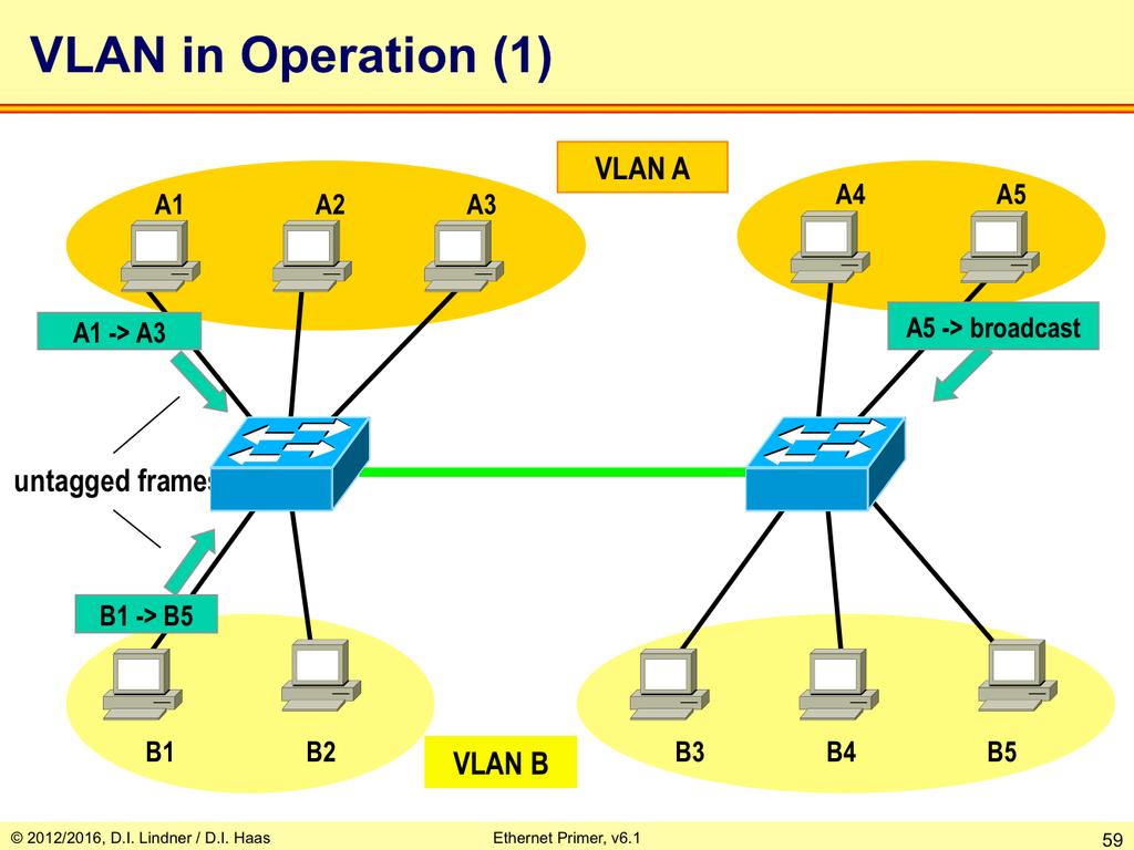
53 Since most organizations consist of multiple "working groups" it is reasonable to confine their produced traffic somehow. Today's work-groups are expanding over the whole campus and users of one workgroup should be kept separated from other workgroups because of security reasons. They should see their necessary working environment only. End-systems of one workgroup should see broadcasts only from stations of same workgroup. But at all the network must be flexible to adapt to continuous location changes of the end-systems/users. This is achieved using Virtual LANs (VLANs). Switches configured for VLANs consist logically of multiple virtual switches inside. Users/End systems are assigned to dedicated VLANs and there is no communication possible between different VLANs even broadcasts are blocked! This significantly enhances security. On an Ethernet switch each VLAN is identified by a number and a name (optionally) but in our example we also use colors to differentiate them. Ethernet switches supporting VLAN technique maintain separate bridging/switching tables per VLAN, handle separate broadcast domains per VLAN, but still have to deal with spanning-tree. There are several solutions how to implement STP in case of VLANs: 1) original 802.1D standard specifies one single STP to be used for all VLANs together. That means the traffic of all VLANs travels along the same Spanning-Tree. 2) Cisco implements a per-vlan STP. That means by differently tuning STP parameters per VLAN, different links are used by the VLAN traffic. 3) Later the MST (Multiple Instances Spanning Tree) standard allows something similar to the Cisco solution. The difference to Cisco is the better scalability if a large number of VLANs is used. MST allows to deal with a number of necessary Spanning-Trees given by the specific topology but avoids Spanning-Trees per VLAN. Page - 53

54 There are different ways to assign hosts (users) to VLANs. The most common is the portbased assignment, meaning that each port has been configured to be member of a VLAN. Simply attach a host there and its user belongs to that VLAN specified. Hosts can also be assigned to VLANs by their MAC address. Also special protocols can be assigned to dedicated VLANs, for example management traffic. Furthermore, some devices allow complex rules to be defined for VLAN assignment, for example a combination of address, protocol, etc. Example how a station may be assigned to a VLAN: Port-based: fixed assignment port 4 -> VLAN x, most common approach, a station is member of one specific VLAN only, administrator has to reconfigure a switch in order to support a location change of a user. MAC-address based: MAC A -> VLAN x, allows integration of older shared-media components and automatic location change support, a station is member of one specific VLAN only. Protocol-based: IP-traffic, port 1 -> VLAN x and NetBEUI-traffic, port 1 -> VLAN y, a station could be member of different VLANs 802.1X-based: User A -> VLAN engineering, User B -> VLAN finance, automatic location change support. Of course VLANs should span over several bridges. This is supported by special VLAN trunking protocols, which are only used on the trunk between two switches. Two important protocols are commonly used: the IEEE 802.1q protocol and the Cisco Inter-Switch Link (ISL) protocol. Both protocols basically attach a "tag" at each frame which is sent over the trunk. Page - 54

55 By using VLAN tagging the "next" bridge knows whether the source address is also member of the same VLAN. Page - 55

56 Page - 56
57 Page - 57
58 Page - 58
59 Page - 59

60 Page - 60

61 Page - 61
62 Page - 62
63 Page - 63

64 Page - 64

65 Now we admit the wholly truth: of course it is possible to communicate between different VLANs using a router! A router terminates layer 2 and is not interested in VLAN constraints. Of course this requires that each VLAN uses another subnet IP address since the router needs to make a routing decision. There are two possible configurations: The straightforward solutions is to attach a router to several ports on one or more switches, provided that each port is member of another VLAN. Another method is the "Router on a stick" configuration, employing only a single attachment to a trunk port of a switch. This method saves ports (and cables) but requires trunking functionality on the router. Here the router simply changes the tag of each frame (after making a routing decision) and sends the frame back to the switch. Page - 65
66 On trunks between multiport switches full duplex operation is used of course. In case of parallel trunks the normal operation of STP will block one trunk link and hence bandwidth of this link can not be used. Several techniques were developed by vendors and IEEE standardization to allow load balancing on a session-base in such a situation, meaning both trunks can be used for traffic forwarding. Bundling (aggregation) of physical links to one logical link which is seen by STP - can be done with: 1. Fast Ethernet Channeling (FEC, Cisco), up to eight active ports can be bundled. 2. Gigabit Ethernet Channeling (GEC Cisco), up to eight active ports can be bundled. 3. Linux Bonding. 4. IEEE 802.1AX 2008 LACP (Link Aggregation Control Protocol), up to eight active ports can be bundled. Note1: LACP appeared first in IEEE version 2002, nowadays handled in a separate standard IEEE 802.1AX-2008) Note2: LACP is defined between switch and switch or end station and one switch but not between end-system and two switches. Although some vendor have proprietary solutions which allows two physical switches acting as one logical switch so that LACP can also be used between an end-system and two physical switches. Of course, if a per-vlan STP is used like in PVST+ or multiple instances of STP are possible like in MSTP, then by STP-tuning of VLAN orange to use trunk 1 and STP-tuning of VLAN yellow to use trunk 2 a alternate method exiists for solving that problem. Page - 66
67 Page - 67
68 Page - 68

69 Page - 69

70 Radia Perlman, PhD computer science 1988, MIT * MS math 1976, MIT * BA math 1973, MIT Radia Perlman specializes in network and security protocols. She is the inventor of the spanning tree algorithm used by bridges, and the mechanisms that make modern link state protocols efficient and robust. She is the author of two textbooks, and has a PhD from MIT in computer science. Her thesis on routing in the presence of malicious failures remains the most important work in routing security. She has made contributions in diverse areas such as, in network security, credentials download, strong password protocols, analysis and redesign of IPSec IKE protocols, PKI models, efficient certificate revocation, and distributed authorization. In routing, her contributions include making link state protocols robust and scalable, simplifying the IP multicast model, and routing with policies. Page - 70
.")
71 What do we need for STP to work? First of all this protocol needs a special messaging means, realized in so-called Bridge Protocol Data Units (BPDUs). BPDUs are simple messages contained in Ethernet frames containing several parameters described in the next pages. Page - 71

72 Each bridge is assigned one unique Bridge-ID which is a combination of a 16 bit priority number and the lowest MAC address found on any port on this bridge. The Bridge-ID is determined automatically using the default priority Note: Although bridge will not be seen by end systems, for bridge communication and management purposes a bridge will listen to one or more dedicated (BIA) MAC addresses. Typically, the lowest MAC-address is used for that. The Bridge-ID is used by STP algorithm to determine root bridge and as tie-breaker to when determine the designated port. Page - 72

73 Each port is assigned a Port Cost. Again this value is determined automatically using the simple formula Port Cost = 1000 / BW, where BW is the bandwidth in Mbit/s. Of course the Port Cost can be configured manually. Port Cost are used by STP algorithm to calculate Root Path Cost in order to determine the root port and the designated port Each port is assigned a Port Identifier. Only used by STP algorithm as tie-breaker if the same Bridge-ID and the same Path Cost is received on multiple ports. Page - 73

74 Page - 74

75 Page - 75
 of the network. Page - 76")
76 These creates single paths from the root to all leaves (LAN segments) of the network. Page - 76

77 Page - 77

78 Just for your interest, the above picture shows the structure of BPDUs. You see, there is no magic in here, and the protocol is very simple. There are no complicated protocol procedures. BPDUs are sent periodically and contain all involved parameters. Each bridge enters its own "opinion" there or adds its root path costs to the appropriate field. Note that some parameters are transient and others are not. The other parameters will be explained in the next slides. Page - 78

79 After power up all ports are set in a Blocking State and every bridge tries to become the Root Bridge (RB) of the Spanning Tree by sending Configuration BPDUs. Blocking state means: End station Ethernet frames are not received and forwarded on such a port but BDPU frames can still be received, manipulated by the bridge and transmitted on such port. BPDU frames are actually filtered based on the well-known multicast address and are given to the CPU of the bridge. Using such Configuration BPDUs, a bridge tells, which bridge actually is seen as RB, which path costs exist to this RB (Root Path Cost) and its own Bridge ID and Port ID. Page - 79

80 Bridge with the lowest Bridge ID becomes RB. after selection of the RB all sending of Configuration BPDUs are exclusively triggered by the RB. Other bridges just move such BPDUs on after actualizing the corresponding BPDU fileds. Strategy to determinate the RB : If bridge receives a Configuration BPDU with lower Root Bridge ID as own Bridge ID the bridge stops sending Configuration BPDUs on this port and the received and adapted Configuration BPDU is forwarded to all other ports. If bridge receives Configuration BPDU with higher Root Bridge ID as own Bridge ID the bridge continues sending Configuration BPDUs with own Bridge ID as proposed Root Bridge ID on all ports, the other bridges should give up. Page - 80
81 Now, every bridge determines which of its ports has the lowest Root Path Cost. Root Path Cost = sum of all port costs from this bridge to the RB, including port costs of all intermediate bridges. This port becomes the Root Port. In case of equal costs the port ID decides (lower means better). The principle calculation method: Root Path Cost received in BPDU + port cost of the local port receiving that BPDU. Similar to Root Bridge selection, a Designated Bridge (DB) is selected for each LAN-segment which is the bridge with the lowest Root Path Cost on its Root Port. In case of equal costs the bridge with the lowest Bridge ID wins again. Page - 81

82 Using the Root Path Cost field in the Configuration BPDU, a bridge indicates its distance to the RB. Strategy for decision: If a bridge receives a Configuration BPDU from a bridge which is closer to the RB, the receiving bridge adds its own port costs to the Configuration BPDU and forwards this message to all other ports. If a bridge receives a Configuration BPDU from a bridge which is more distant to the RB, the receiving bridge drops the message and sends its own Configuration BPDU on this port containing its own Root Path Cost. Page - 82

83 Page - 83

84 Procedure Parameters Summary: Root Bridge -> lowest Bridge ID. Root Ports via Root Path Costs -> which sum of costs contained in the Configuration BPDU and the receiving interface Port Costs. Designated Bridge -> lowest Root Path Costs for a given LAN segment. Root switch has only Designated Ports, all of them are in forwarding state. Other switches have exactly one Root Port (RP) upstream, zero or more Designated Ports (DP) downstream and zero or more Nondesignated Ports (blocked). Now every designated bridge declares its ports as designated ports and puts them (together with the Root Port) in the Forwarding State. All other bridges keep their non-rp and non-dp ports in the Blocking State. From this moment on, the normal network operation is possible and there is only one path between any two arbitrary end systems. Redundant links remain in active stand-by mode. If root port fails, other root port becomes active. Still it is reasonable to establish parallel paths in a switched network in order to utilize this redundancy in an event of failure. The STP automatically activates redundant paths if the active path is broken. Note that BPDUs are always sent or received on blocking ports. Note that (very-) low price switches might not support the STP and should not be used in high performance and redundant configurations. Page - 84

85 Page - 85
86 Page - 86

87 Under normal conditions the root bridge generates every hello-time period a Heartbeat - BPDU. All other bridges expected to hear the heartbeat and they have to pass it on in case it is received. If the heartbeat disappears for whatever reason however a new STP will be built. During the time of convergence (between 30 and 50 seconds for the old STP, about up to 3-5 seconds for the RSTP) any-to-any connectivity ind the LAN will be disturbed or prevented, hence we have an outage time in the network. Old STP which is covered in this section is described in the IEEE 802.1D-1998 standard. Page - 87
88 Scenario 1: Designated port (DP) of Bridge 57 fails. Bridge 45 and bridge 83 do not receive the heartbeat on their blocked ports (BP) anymore although heartbeat is seen on their root ports (RP). After max-age time (20 seconds) a new STP is triggered by bridge 45 and bridge 83. Page - 88

89 Scenario 1: Here you see the new topology. Bridge 83 became the designated bridge for LAN5. Page - 89
90 Scenario 2: Root bridge 42 fails. All other bridges do not receive the heartbeat neither on their root ports nor on their blocked ports (BP). After max-age time (20 seconds) a new STP is triggered by all remaining bridges 45. Page - 90
91 Scenario 2: Here you see the new topology. Bridge 45 became the new root bridge. Bridge 57 has equal RPC on both ports hence the port-id decides which is RP and which is BP. Page - 91
92 Scenario 3: RP of Bridge 57 fails. In that case bridge 57 has not to wait for max-age period before triggering the new STP. Reason: Bridge is designated bridge but RP fails and there is no other connectivity to the root bridge possible Yellow arrows show the signposts in the bridging table to reach MAC address A before the failure. Page - 92
93 Scenario 3: Here you see the new topology. Bridge 83 became the new designated bridge for LAN5. Recognize what happens if station D sends a frame to station A. The pointer in bridge 42 still points in the wrong direction and the frame will be filtered by bridge 42 until the entry times out after 5 minutes. Of course if A would send a broadcast frame the table would immediately be repaired but what if not. Hence bridges should install an additional procedure to overcome such situations without interaction of end-system functionality like the mentioned broadcast of A. This procedure is called topology notification. Page - 93
.")
94 Bridge 57 and 83 send TCN BPDUs out on their Root Ports (red arrows: TC bit set). After such a message is received by an upstream bridge it will be locally acknowledged by the upstream bridge in the reverse direction (yellow arrows: TCA bit set). If that finally appears to the root bridge, the root will sent a Conf BPDU with both flags set (orange arrows: TC and TCA bit set) for 35 seconds which has to be passed on downstream by the other bridges. All switches receiving TC+TCA=1 will age out (flush) their bridging tables in 15 seconds instead of waiting for 3 minutes. Page - 94

95 Note: Old STP which is covered in this section is described in the IEEE 802.1D-1998 standard. Page - 95
96 Page - 96

97 RSTP is designed to be compatible and interoperable with the traditional STP (IEEE 802.1D version 1998) without additional management requirements. If an RSTP-enabled bridge is connected to an STP bridge, only Configuration-BPDUs and Topology-Change BPDUs are sent but no port role negotiation is supported. An RSTP Bridge Port automatically adjusts to provide interoperability, if it is attached to the same LAN as an STP Bridge. Protocol operation on other ports is unchanged. Configuration and Topology Change Notification BPDUs are transmitted instead of RST BPDUs which are not recognized by STP Bridges. Port state transition timer values are increased to ensure that temporary loops are not created through the STP Bridge. Topology changes are propagated for longer to support the different FilteringDatabase flushing paradigm used by STP. It is possible that RSTP s rapid state transitions will increase rates of frame duplication and misordering. BPDUs convey Configuration and Topology Change Notification (TCN) Messages. A Configuration Message can be encoded and transmitted as a Configuration BPDU or as an RST BPDU. A TCN Message can be encoded as a TCN BPDU or as an RST BPDU with the TC flag set. The Port Protocol Migration state machine determines the BPDU types used. In most cases, RSTP performs better than Cisco's proprietary extensions (Port-Fast, Uplink- Fast, Backbone-Fast) without any additional configuration w is also capable of reverting back to 802.1d in order to interoperate with legacy bridges (thus dropping the benefits it introduces) on a per-port basis. Page - 97

98 Remember: Root Port Role: Receives the best BPDU (so it is closest to the root bridge). Designated Port Role: A port is designated if it can send the best BDPU on the segment to which it is connected. On a given segment, there can be only one path towards the root-bridge. Page - 98

99 There are only 3 port states left in RSTP, corresponding to the 3 possible operational states. The 802.1d states disabled, blocking and listening have been merged into a unique 802.1w discarding state. There is no difference between a port in blocking state and a port in listening state; they both discard frames and do not learn MAC addresses. The real difference lies in the role the spanning tree assigns to the port. It can safely be assumed that a listening port will be either a designated or root and is on its way to the forwarding state. Unfortunately, once in forwarding state, there is no way to detect from the port state whether the port is root or designated, which contributes to demonstrating the failure of this state-based terminology. RSTP addresses this by decoupling the role and the state of a port. The role is now a variable assigned to a given port. The root port and designated port roles remain, while the blocking port role is now split into the backup and alternate port roles. A non-designated port is a blocked port that receives a more useful BPDU than the one it would send out on its segment. The "more useful BPDU" can be received from the same switch (on another port on the same LAN segment) or from another switch (also on the same LAN segment). The first is called a backup port, the latter an alternate port. Note: To make the confusion even worse -> The name blocking is used for the discarding state in Cisco implementations!!! Page - 99

100 AP alternate port, BP is now backup port. Alternate Port: A port blocked by receiving better BPDUs from a different bridge. It provides an alternate path to the root bridge Backup Port: A port blocked by receiving better BPDUs from the same bridge. Provides a redundant connectivity to the same segment. Page - 100
 and TCN (bit 0) 3) BPDU type differentiate between CONF BPD and TCN BPDU Note2: If the Unknown value of the Port Role parameter is")
101 Note1: A Configuration BPDU has same structure than a RSTP BPDU with the following exceptions: 1) A Configuration BPDU is only 35 byte long, that is, there is no "Version 1 length" field 2) A Configuration BPDU only uses two flags, that is, TCAck (bit 7) and TCN (bit 0) 3) BPDU type differentiate between CONF BPD and TCN BPDU Note2: If the Unknown value of the Port Role parameter is received, the state machines will effectively treat the RST BPDU as if it were a Configuration BPDU. Flags: TCN (bit 1) Proposal (bit 2) Port Role (bits 3, 4) Learning (bit 5) Forwarding (bit 6) Agreement (bit 7) Topology Change Acknowledgment (bit 8) Page - 101

102 The new bits encode the role state of the port originating the BPDU and handle the proposal/ agreement mechanism. Page - 102

103 There is an explicit handshake between bridges upon link up event. The bridge sends a proposal to become designated for that segment. The remote bridge responses with an agreement if the port on which it received the proposal is the root port of the remote bridge. As soon as receiving an agreement, the bridge moves the port to the forwarding state. If the remote bridge has a better role like it is nearer to the root bridge or is the root bridge itself, it will not accept the proposal but will send an own proposal. Whatever is that case, the role and state of the ports is settled within exchange of 2 or 4 messages. Page - 103

104 Rapid Transition to Forwarding State is the most important feature in 802.1w. The legacy STP was passively waiting for the network to converge before turning a port into the forwarding state New RSTP is able to actively confirm that a port can safely transition to forwarding. It is a real feedback mechanism, that takes place between RSTP-compliant bridges through proposal / agreement sequence. Page - 104

105 On a given port, if hellos are not received three consecutive times, protocol information can be immediately aged out (or if max-age expires). Because of the previously mentioned protocol modification, BPDUs are now used as a keepalive mechanism between bridges. A bridge considers that it loses connectivity to its direct neighbor root or designated bridge if it misses three BPDUs in a row. This fast aging of the information allows quick failure detection. If a bridge fails to receive BPDUs from a neighbor, it is certain that the connection to that neighbor is lost. This is opposed to 802.1D where the problem might have been anywhere on the path to the root. Rapid transition is the most important feature introduced by 802.1w. The legacy STP passively waited for the network to converge before it turned a port into the forwarding state. The achievement of faster convergence was a matter of tuning the conservative default parameters (forward delay and max-age timers) and often put the stability of the network at stake. The new rapid STP is able to actively confirm that a port can safely transition to the forwarding state without having to rely on any timer configuration. There is now a real feedback mechanism that takes place between RSTP-compliant bridges. In order to achieve fast convergence on a port, the protocol relies upon two new variables: edge ports and link type. Page - 105

106 RSTP can only achieve rapid transition to forwarding: on edge ports (either full-duplex or halfduplex) or on point-to-point links (trunks between L2 switches using full-duplex), but not on shared links. Edge ports, which are directly connected to end stations, cannot create bridging loops in the network and can thus directly perform on link setup transition to forwarding, skipping the listening and learning states of old STP. Link type shared or point-to-point is automatically derived from the physical duplex mode of a port: A port operating in full-duplex will be assumed to be point-to-point, a port operating in halfduplex will be assumed to be a shared port. Page - 106

107 Page - 107

108 Page - 108

109 Page - 109

110 Page - 110

111 Page - 111

112 Page - 112
113 Page - 113

114 Page - 114
 requires frame format changing which makes it slower).")
115 Ethernet MAC frame format was preserved up nowadays. Bridging from 10 Mbit/s Ethernet to 100 Mbit/s Ethernet does not require a bridge to change the frame format. (Remark: bridging from 10 Mbit/s Ethernet to FDDI (100 Mbit/s Token ring) requires frame format changing which makes it slower). Therefore Ethernet L2 switches can connect Ethernets with 10 Mbit/s, 100 Mbit/s or 1000 Mbit/s easily and fast. Page - 115
. Now CSMA/CD is not in necessary and can be switched off.")
116 Note: Full-duplex mode is possible on point-to-point links between two elements in the network (end-system to switch, switch to switch, end-system to end-system) if there are two physical communication paths available (2 fiber optic links or 4 copper wires used for symmetrical transmission). Now CSMA/CD is not in necessary and can be switched off. A station can send frames immediately (without CS) using the transmit-line of the cable and simultaneously receive data on the other line. At both end of the link we have store and forward behavior hence collision detection (CD) is not necessary anymore. Page - 116

117 Page - 117

118 Different data rates between switches (and different performance levels) often lead to congestion conditions, full buffers, and frame drops. Traditional Ethernet flow control was only supported on half-duplex links by enforcing collisions to occur and hereby triggering the truncated exponential backoff algorithm. Just let a collision occur and the aggressive sender will be silent for a while. A much finer method is to send some dummy frames just before the backoff timer allows sending. This way the other station never comes to send again. Both methods are considered as ugly and only work on half duplex lines. Therefore the MAC Control frames were specified, allowing for active flow control. Now the receiver sends this special frame, notifying the sender to be silent for N slot times. The MAC Control frame originates in a new Ethernet layer the MAC Control Layer and will support also other functionalities, but currently only the "Pause" frame has been specified. Page - 118

119 Page - 119

120 Page - 120

121 Today, Gigabit and even 10 Gigabit Ethernet is available. Only twisted pair and more and more fiber cables are used between switches, allowing full duplex collision-free connections. Since collisions cannot occur anymore, there is no need for a collision window anymore! From this it follows, that there is virtually no distance limit between each two Ethernet devices. Recent experiments demonstrated the interconnection of two Ethernet Switches over a span of more than 100 km! Thus Ethernet became a WAN technology! Today, many carriers use Ethernet instead of ATM/SONET/SDH or other rather expensive technologies. GE and 10GE is relatively cheap and much simpler to deploy. Furthermore it easily integrates into existing lowrate Ethernet environments, allowing a homogeneous interconnection between multiple Ethernet LAN sites. Basically, the deployment is plug and play. If the link speed is still too slow, so-called "Etherchannels" can be configured between each two switches by combining several ports to one logical connection. Note that it is not possible to deploy parallel connections between two switches without an Etherchannel configuration because the Spanning Tree Protocol (STP) would cut off all redundant links. Depending on the vendor, up to eight ports can be combined to constitute one "Etherchannel". Page - 121
122 Page - 122

123 The diagram above gives an overview of 100 Mbit/s Ethernet technologies, which are differentiated into IEEE 802.3u and IEEE standards. The IEEE 802.3u defines the widely used Fast Ethernet variants, most importantly those utilizing the 100BaseX signaling scheme. The 100BaseX signaling consists of several details, but basically it utilizes 4B5B block coding over only two pairs of regular Cat 5 twisted pair cables or two strand 50/125 or 62.5/125-µm multimode fiber-optic cables. 100Base4T+ signaling has been specified to support 100 Mbit/s over Cat3 cables. This mode allows half duplex operation only and uses a 8B6T code over 4 pairs of wires; one pair for collision detection, three pairs for data transmission. One unidirectional pair is used for sending only and two bi-directional pairs for both sending and receiving. The 100VG-AnyLAN technology had been created by HP and AT&T in 1992 to support deterministic medium access for realtime applications. This technology was standardized by the IEEE working group. The access method is called "demand priority". 100VG- AnyLAN supports voice grade cables (VG) but requires special hub hardware. The working group is no longer active. Page - 123
 to verify layer 2 connectivity. NLPs are single pulses which must be received periodically between regular frames.")
124 Several Ethernet operating modes had been defined, which are incompatible to each other, including different data rates (10, 100, 1000 Mbit/s), half or full duplex operation, MAC control frames capabilities, etc. Original Ethernet utilized so-called Normal Link Pulses (NLPs) to verify layer 2 connectivity. NLPs are single pulses which must be received periodically between regular frames. If NLPs are received, the green LED on the NIC is turned on. Newer Ethernet cards realize auto negotiation by sending a sequence of NLPs, which is called a Fast Link Pulse (FLP) sequence. Page - 124
125 A series of FLPs constitute an autonegotiation frame. The whole frame consists of 33 timeslots, where each odd numbered timeslot consists of a real NLP and each even timeslot is either a NLP or empty, representing 1 or 0. Thus, each FLP sequence consists of a 16 bit word. Note that GE Ethernet sends several such "pages". Page - 125

126 Page - 126

127 Page - 127
 If the base-page has been received 3 times with the NP set to zero, the receiver station responds with the Ack bit set to 1 If next-pages are following, the receiver responds with")
128 Remote Fault (RF) Signals that the remote station has recognized an error Next Page (NP) Signals following next-page(s) after the base-page Acknowledge (Ack) Signals the receiving of the data (not the feasibility) If the base-page has been received 3 times with the NP set to zero, the receiver station responds with the Ack bit set to 1 If next-pages are following, the receiver responds with Ack=1 after receiving 3 FLP-bursts Page - 128
 Provides synchronization during exchange of next-pages information T-bit is always set to the inverted value of the 11th bit of the last received link-codeword Page -")
129 Acknowledge 2 (Ack2) Ack2 is set to 1 if station can perform the declared capabilities Message Page (MP) Differentiates between message-pages (MP=1) and Unformatted-pages (MP=0) Toggle (T) Provides synchronization during exchange of next-pages information T-bit is always set to the inverted value of the 11th bit of the last received link-codeword Page - 129
130 Page - 130

131 Page - 131

132 Gigabit Ethernet has been defined in March 1996 by the working group IEEE 802.3z. The GMII represents a abstract interface between the common Ethernet layer 2 and different signaling layers below. Two important signaling techniques had been defines: The standard 802.3z defines 1000Base-X signaling which uses 8B10B block coding and the 802.3ab standard uses 1000Base-T signaling. The latter is only used over twisted pair cables (UTP Cat 5 or better), while 1000BaseX is only used over fiber, with one exception, the twinax cable (1000BaseCX), which is basically a shielded twisted pair cable. Page - 132

133 Remember: CSMA/CD requires that stations have to listen (CS) twice the signal propagation time to detect collisions. A collision window of 512 bit times at a rate of 1Gbit/s limits the maximal net expansion to 20m! Page - 133
 can have normal length (i.e. at least 64 bytes) Page - 134")
134 If a station decides to chain several frames to a burst frame, the first frame inside the burst frame must have a length of at least 512 bytes by using extension bytes if necessary. The next frames (inside the burst frame) can have normal length (i.e. at least 64 bytes) Page - 134

135 Page - 135

136 Autonegotiation is part of the Physical Coding sublayer (PCS). Content of base-page register is transmitted via ordered set /C/. On receiving the same packet three times in a row the stations replies with the Ack -bit set. Next-pages can be announced via the next-page bit NP. Page - 136

137 Page - 137
 Provides synchronization during exchange of next-pages information T-bit is always set to the inverted value of the 11th bit of the last received link-codeword Page -")
138 Acknowledge 2 (Ack2) Ack2 is set to 1 if station can perform the declared capabilities Message Page (MP) Differentiates between message-pages (MP=1) and Unformatted-pages (MP=0) Toggle (T) Provides synchronization during exchange of next-pages information T-bit is always set to the inverted value of the 11th bit of the last received link-codeword Page - 138

139 Page - 139
140 Page - 140

141 Originally the 10 GE only supports optical links. Note that GE is actually a synchronous protocol! There is no statistical multiplexing done at the physical layer anymore, because optical switching at that bit rate only allows synchronous transmissions. On fiber its difficult to deal with asynchronous transmission, photons cannot be buffered easily, store and forward problems The GMII has been replaced (or enhanced) by the so-called XAUI, known as "Zowie". As a WAN technology 10GE is much simpler than ATM (hopefully cheaper) but of course it can not be compared with cell switching based on store and forward and sophisticated QoS support. Page - 141

142 Page - 142

143 Page - 143

144 Page - 144
 are re-used from older Ethernet technologies and have not been designed to support such high frequencies.")
145 GE and 10GE over copper is a challenge because of radiation/emi, grounding problems, high BER, thick cable bundles (especially Cat-7). Often the whole electrical hardware (cables and connectors) are re-used from older Ethernet technologies and have not been designed to support such high frequencies. For example the RJ45 connector is not HF proof. Furthermore, shielded twisted pair cables require a very good grounding, seldom found in reality. The Bit Error Rate (BER) is typically so high that the effective data rate is much lower than GE, for example 30% only. Think about that before you use GE or 10GE over copper! Page - 145
Packet Switching on L2 (LAN Level)
") Packet Switching on L2 (LAN Level) Transparent Bridging (TB), Spanning Tree Protocol (STP), Rapid STP, L2 Bridging versus L3 Routing Agenda Introduction Transparent Bridging Basics Spanning Tree Protocol
Packet Switching on L2 (LAN Level) Transparent Bridging (TB), Spanning Tree Protocol (STP), Rapid STP, L2 Bridging versus L3 Routing Agenda Introduction Transparent Bridging Basics Spanning Tree Protocol
Packet Switching on L2 (LAN Level)
") Packet Switching on L2 (LAN Level) Transparent Bridging (TB), Spanning Tree Protocol (STP), Rapid STP, L2 Bridging versus L3 Routing Agenda Introduction Transparent Bridging Basics Principles Broadcast
Packet Switching on L2 (LAN Level) Transparent Bridging (TB), Spanning Tree Protocol (STP), Rapid STP, L2 Bridging versus L3 Routing Agenda Introduction Transparent Bridging Basics Principles Broadcast
Agenda. Spanning-Tree Protocol. Spanning Tree Protocol (STP) Introduction Details Convergence Some more details
 Introduction Details Convergence Some more details") Agenda Spanning-Tree Protocol Spanning Tree Protocol (STP) Introduction Details Convergence Some more details Rapid Spanning Tree Protocol (RSTP) Cisco PVST, PVST+ Multiple Spanning Tree Protocol (MSTP)
Agenda Spanning-Tree Protocol Spanning Tree Protocol (STP) Introduction Details Convergence Some more details Rapid Spanning Tree Protocol (RSTP) Cisco PVST, PVST+ Multiple Spanning Tree Protocol (MSTP)
Spanning-Tree Protocol
 Spanning-Tree Protocol Spanning Tree Protocol (IEEE 802.1D 1998), Rapid STP (IEEE 802.1D 2004), Cisco PVST+, MSTP Page 07-1 Agenda Spanning Tree Protocol (STP) Introduction Details Convergence Some more
Why Packet Switching on LAN? Packet Switching on L2 (LAN Level) Bridge / Router. Agenda
 Bridge / Router. Agenda") Why Packet Switching on LN? Packet Switching on L2 (LN Level) Transparent Bridging (TB), Spanning Tree Protocol (STP), Rapid STP, L2 Bridging versus L3 Routing LN was primarily designed for shared media
Why Packet Switching on LN? Packet Switching on L2 (LN Level) Transparent Bridging (TB), Spanning Tree Protocol (STP), Rapid STP, L2 Bridging versus L3 Routing LN was primarily designed for shared media
Configuring Rapid PVST+ Using NX-OS
 Configuring Rapid PVST+ Using NX-OS This chapter describes how to configure the Rapid per VLAN Spanning Tree (Rapid PVST+) protocol on Cisco NX-OS devices. This chapter includes the following sections:
Transparent Bridging and VLAN
 Transparent Bridging and VLAN Plug and Play Networking (C) Herbert Haas 2005/03/11 Algorhyme I think that I shall never see a graph more lovely than a tree a graph whose crucial property is loop-free connectivity.
Configuring Rapid PVST+
 This chapter describes how to configure the Rapid per VLAN Spanning Tree (Rapid PVST+) protocol on Cisco NX-OS devices using Cisco Data Center Manager (DCNM) for LAN. For more information about the Cisco
Configuring Rapid PVST+
 This chapter contains the following sections: Information About Rapid PVST+, page 1, page 16 Verifying the Rapid PVST+ Configuration, page 24 Information About Rapid PVST+ The Rapid PVST+ protocol is the
Understanding Rapid Spanning Tree Protocol (802.1w)
") Understanding Rapid Spanning Tree Protocol (802.1w) Contents Introduction Support of RSTP in Catalyst Switches New Port States and Port Roles Port States Port Roles New BPDU Format Full View of the Cisco
Understanding Rapid Spanning Tree Protocol (802.1w) Contents Introduction Support of RSTP in Catalyst Switches New Port States and Port Roles Port States Port Roles New BPDU Format Full View of the Cisco
The multiple spanning-tree (MST) implementation is based on the IEEE 802.1s standard.
 implementation is based on the IEEE 802.1s standard.") CHAPTER 18 This chapter describes how to configure the Cisco implementation of the IEEE 802.1s Multiple STP (MSTP) on the IE 3010 switch. Note The multiple spanning-tree (MST) implementation is based on
CHAPTER 18 This chapter describes how to configure the Cisco implementation of the IEEE 802.1s Multiple STP (MSTP) on the IE 3010 switch. Note The multiple spanning-tree (MST) implementation is based on
Table of Contents. Cisco Understanding Rapid Spanning Tree Protocol (802.1w)
") Table of Contents Understanding Rapid Spanning Tree Protocol (802.1w)...1 Introduction...1 Support of RSTP in Catalyst Switches...2 New Port States and Port Roles...2 Port States...2 Port Roles...3 New
Table of Contents Understanding Rapid Spanning Tree Protocol (802.1w)...1 Introduction...1 Support of RSTP in Catalyst Switches...2 New Port States and Port Roles...2 Port States...2 Port Roles...3 New
Interface The exit interface a packet will take when destined for a specific network.
 The Network Layer The Network layer (also called layer 3) manages device addressing, tracks the location of devices on the network, and determines the best way to move data, which means that the Network
Primer Ethernet Technology
 Primer Ethernet Technology From 10Mbit/s to 10Gigabit/s Ethernet Technology From Bridging to L2 Ethernet Switching and VLANs From Spanning-Tree to Rapid Spanning-Tree Agenda Ethernet Origins Transparent
Table of Contents 1 MSTP Configuration 1-1
 Table of Contents 1 MSTP Configuration 1-1 Overview 1-1 Introduction to STP 1-1 Why STP 1-1 Protocol Packets of STP 1-1 Basic Concepts in STP 1-2 How STP works 1-3 Introduction to RSTP 1-9 Introduction
Ethernet. Agenda. Introduction CSMA/CD Elements and Basic Media-Types Repeater, Link Segments Framing. L21 - Ethernet
 Ethernet CSMA/CD, Framing, SNAP, Repeater, Hub, 10Mbit/s Technology Agenda Introduction CSMA/CD Elements and Basic Media-Types Repeater, Link Segments Framing Ethernet, v4.7 2 Page 21-1 Origin of IEEE
Origin of IEEE (Ethernet) Ethernet. Agenda. Basic Idea of Ethernet Bus System
 Ethernet. Agenda. Basic Idea of Ethernet Bus System") Origin of IEEE 802.3 (Ethernet) Ethernet CSMA/CD, Framing, SNAP, Repeater, Hub, 10Mbit/s Technology bus topology based on coax-cables passive, uninterrupted coupling shared media like the Ether of air
Origin of IEEE 802.3 (Ethernet) Ethernet CSMA/CD, Framing, SNAP, Repeater, Hub, 10Mbit/s Technology bus topology based on coax-cables passive, uninterrupted coupling shared media like the Ether of air
Configuring STP and RSTP
 7 CHAPTER Configuring STP and RSTP This chapter describes the IEEE 802.1D Spanning Tree Protocol (STP) and the ML-Series implementation of the IEEE 802.1W Rapid Spanning Tree Protocol (RSTP). It also explains
Part3. Local Area Networks (LAN)
") Part3 Local Area Networks (LAN) LAN Characteristics Small geographical area Relatively high data rate Single management Topologies Bus, star, ring Specifications at physical and data link layer mostly
Part3 Local Area Networks (LAN) LAN Characteristics Small geographical area Relatively high data rate Single management Topologies Bus, star, ring Specifications at physical and data link layer mostly
Table of Contents. (Rapid) Spanning Tree Protocol. A simple bridge loop. An even worse bridge loop. Bridge loops Two bridges Three bridges (R)STP
 Spanning Tree Protocol. A simple bridge loop. An even worse bridge loop. Bridge loops Two bridges Three bridges (R)STP") Table of Contents (Rapid) Spanning Tree Protocol (R)STP Karst Koymans Informatics Institute University of Amsterdam (version 18.4, 2018/11/16 13:23:04) Friday, November 16, 2018 Bridge loops Two bridges
Table of Contents (Rapid) Spanning Tree Protocol (R)STP Karst Koymans Informatics Institute University of Amsterdam (version 18.4, 2018/11/16 13:23:04) Friday, November 16, 2018 Bridge loops Two bridges
Configuring Spanning Tree Protocol
 Finding Feature Information, page 1 Restrictions for STP, page 1 Information About Spanning Tree Protocol, page 2 How to Configure Spanning-Tree Features, page 14 Monitoring Spanning-Tree Status, page
IEEE 802 LANs SECTION C
 IEEE 802 LANs SECTION C Outline of the Lecture Basic characteristics of LAN Topology Transmission Media MAC IEEE 802 LANs 802.3 - CSMA/CD based (Ethernet) 802.4 Token bus-based 802.5 Token ring-based Comparison
Lecture (04) Network Layer (Physical/Data link) 2
 Network Layer (Physical/Data link) 2") Lecture (04) Network Layer (Physical/Data link) 2 By: Dr. Ahmed ElShafee ١ Dr. Ahmed elshafee, ACU : Spring 2018, CSE401 Computer Networks Agenda Ethernet standards 10 base 5 10 base 2 10 base T Fast Ethernet
Lecture (04) Network Layer (Physical/Data link) 2 By: Dr. Ahmed ElShafee ١ Dr. Ahmed elshafee, ACU : Spring 2018, CSE401 Computer Networks Agenda Ethernet standards 10 base 5 10 base 2 10 base T Fast Ethernet
The Spanning Tree 802.1D (2004) RSTP MSTP
 RSTP MSTP") The Spanning Tree 802.1D (2004) RSTP MSTP (C) Herbert Haas 2005/03/11 http://www.perihel.at 1 Problem Description We want redundant links in bridged networks But transparent bridging cannot deal with redundancy
The Spanning Tree 802.1D (2004) RSTP MSTP (C) Herbert Haas 2005/03/11 http://www.perihel.at 1 Problem Description We want redundant links in bridged networks But transparent bridging cannot deal with redundancy
Configuring STP and Prestandard IEEE 802.1s MST
 20 CHAPTER This chapter describes how to configure the Spanning Tree Protocol (STP) and prestandard IEEE 802.1s Multiple Spanning Tree (MST) protocol on Catalyst 6500 series switches. Note The IEEE 802.1s
Configuring STP. Understanding Spanning-Tree Features CHAPTER
 CHAPTER 11 This chapter describes how to configure the Spanning Tree Protocol (STP) on your switch. For information about the Rapid Spanning Tree Protocol (RSTP) and the Multiple Spanning Tree Protocol
Configuring Spanning Tree Protocol
 Restrictions for STP Restrictions for STP, on page 1 Information About Spanning Tree Protocol, on page 1 How to Configure Spanning-Tree Features, on page 13 Monitoring Spanning-Tree Status, on page 25
MSTP Technology White Paper
 MSTP Technology White Paper Key words: STP, RSTP, MSTP, rapid transition, multiple instances, redundancy loop, redundancy link, load sharing Abstract: This article introduces basic MSTP terms, MSTP algorithm
Table of Contents Chapter 1 MSTP Configuration
 Table of Contents Table of Contents... 1-1 1.1 MSTP Overview... 1-1 1.1.1 MSTP Protocol Data Unit... 1-1 1.1.2 Basic MSTP Terminologies... 1-2 1.1.3 Implementation of MSTP... 1-6 1.1.4 MSTP Implementation
Top-Down Network Design
 Top-Down Network Design Chapter Seven Selecting Switching and Routing Protocols Original slides by Cisco Press & Priscilla Oppenheimer Selection Criteria for Switching and Routing Protocols Network traffic
Spanning Tree Protocol(STP)
") Introduction Spanning Tree Protocol (STP) is a Layer 2 protocol that runs on bridges and switches. The specification for STP is IEEE 802.1D. The main purpose of STP is to ensure that you do not create
Introduction Spanning Tree Protocol (STP) is a Layer 2 protocol that runs on bridges and switches. The specification for STP is IEEE 802.1D. The main purpose of STP is to ensure that you do not create
Spanning-Tree Protocol
 Spanning-Tree Protocol Agenda» What Problem is Solved by STP?» Understanding STP Root Bridge Election» BPDU Details and Pathcost» Understanding STP Root and Designated Port Election» Understanding and
Configuring MST Using Cisco NX-OS
 This chapter describes how to configure Multiple Spanning Tree (MST) on Cisco NX-OS devices. This chapter includes the following sections: Finding Feature Information, page 1 Information About MST, page
Lecture (04) Data link layer
 Data link layer") Lecture (04) Data link layer By: Dr. Ahmed ElShafee Standards Overview CSMA/CD Ethernet standards 10 base 5 10 base 2 10 base T Fast Ethernet Gigabit Ethernet ١ ٢ Standards Overview Like most protocols,
Lecture (04) Data link layer By: Dr. Ahmed ElShafee Standards Overview CSMA/CD Ethernet standards 10 base 5 10 base 2 10 base T Fast Ethernet Gigabit Ethernet ١ ٢ Standards Overview Like most protocols,
Objectives. Hexadecimal Numbering and Addressing. Ethernet / IEEE LAN Technology. Ethernet
 2007 Cisco Systems, Inc. All rights reserved. Cisco Public Objectives Ethernet Network Fundamentals Chapter 9 ITE PC v4.0 Chapter 1 1 Introduce Hexadecimal number system Describe the features of various
Implement Spanning Tree Protocols-PART-I. LAN Switching and Wireless Chapter 5 Modified by Tony Chen 05/01/2008
 Implement Spanning Tree Protocols-PART-I LAN Switching and Wireless Chapter 5 Modified by Tony Chen 05/01/2008 ITE I Chapter 6 2006 Cisco Systems, Inc. All rights reserved. Cisco Public 1 Notes: If you
Table of Contents. (Rapid) Spanning Tree Protocol. An even worse bridge loop. A simple bridge loop. Bridge loops Two bridges Three bridges (R)STP
 Spanning Tree Protocol. An even worse bridge loop. A simple bridge loop. Bridge loops Two bridges Three bridges (R)STP") Table of Contents (Rapid) Spanning Tree Protocol (R)STP Karst Koymans Informatics Institute University of Amsterdam (version 44, 2015/02/18 12:55:30) Thursday, February 19, 2015 Bridge loops Two bridges
Table of Contents (Rapid) Spanning Tree Protocol (R)STP Karst Koymans Informatics Institute University of Amsterdam (version 44, 2015/02/18 12:55:30) Thursday, February 19, 2015 Bridge loops Two bridges
802.1w Rapid Spanning Tree Protocol (RSTP) 802.1d Spanning Tree Protocol (STP)
 802.1d Spanning Tree Protocol (STP)") 13 802.1w Rapid Spanning Tree Protocol (RSTP) 802.1d Spanning Tree Protocol (STP) Contents Overview.................................................... 13-2 How Spanning Tree Operates.................................
13 802.1w Rapid Spanning Tree Protocol (RSTP) 802.1d Spanning Tree Protocol (STP) Contents Overview.................................................... 13-2 How Spanning Tree Operates.................................
DD2490 p Layer 2 networking. Olof Hagsand KTH CSC
 DD2490 p4 2010 Layer 2 networking Olof Hagsand KTH CSC 1 Literature Radia Pearlman Interconnections - Bridges, Routers, Switches and Internetworking Protocols, Addison-Wesley. Section 3: Transparent bridges
Table of Contents. (Rapid) Spanning Tree Protocol. A simple bridge loop. An even worse bridge loop. Bridge loops Two bridges Three bridges (R)STP
 Spanning Tree Protocol. A simple bridge loop. An even worse bridge loop. Bridge loops Two bridges Three bridges (R)STP") Table of Contents (Rapid) Spanning Tree Protocol (R)STP Karst Koymans Informatics Institute University of Amsterdam (version 34, 2014/02/17 14:41:48) Monday, February 17, 2014 Bridge loops Two bridges
Table of Contents (Rapid) Spanning Tree Protocol (R)STP Karst Koymans Informatics Institute University of Amsterdam (version 34, 2014/02/17 14:41:48) Monday, February 17, 2014 Bridge loops Two bridges
Introduction to OSPF
 Campus Networking Introduction to OSPF Workshop Campus Layer-2 Networking Network Workshop Design These materials are licensed under the Creative Commons Attribution-Noncommercial 3.0 Unported license
More on LANS. LAN Wiring, Interface
 More on LANS Chapters 10-11 LAN Wiring, Interface Mostly covered this material already NIC = Network Interface Card Separate processor, buffers incoming/outgoing data CPU might not be able to keep up network
Token Ring VLANs and Related Protocols
 Token Ring VLANs and Related Protocols CHAPTER 4 Token Ring VLANs A VLAN is a logical group of LAN segments, independent of physical location, with a common set of requirements. For example, several end
62HConfiguring port role restriction 131H37. 63HConfiguring TC-BPDU transmission restriction 132H38. 64HEnabling TC-BPDU guard 133H38
 Contents Configuring spanning tree protocols 3 STP 3 STP protocol packets 3 Basic concepts in STP 4 Calculation process of the STP algorithm 5 RSTP 9 MSTP 10 MSTP features 10 MSTP basic concepts 10 How
CCNA Exploration Network Fundamentals. Chapter 09 Ethernet
 CCNA Exploration Network Fundamentals Chapter 09 Ethernet Updated: 07/07/2008 1 9.0.1 Introduction 2 9.0.1 Introduction Internet Engineering Task Force (IETF) maintains the functional protocols and services
THE OSI MODEL. Application Presentation Session Transport Network Data-Link Physical. OSI Model. Chapter 1 Review.
 THE OSI MODEL Application Presentation Session Transport Network Data-Link Physical OSI Model Chapter 1 Review By: Allan Johnson Table of Contents Go There! Go There! Go There! Go There! Go There! Go There!
ET4254 Communications and Networking 1
 Topic 10:- Local Area Network Overview Aims:- LAN topologies and media LAN protocol architecture bridges, hubs, layer 2 & 3 switches 1 LAN Applications (1) personal computer LANs low cost limited data
3. INTERCONNECTING NETWORKS WITH SWITCHES. THE SPANNING TREE PROTOCOL (STP)
") 3. INTERCONNECTING NETWORKS WITH SWITCHES. THE SPANNING TREE PROTOCOL (STP) 3.1. STP Operation In an extended Ethernet network (a large network, including many switches) multipath propagation may exist
3. INTERCONNECTING NETWORKS WITH SWITCHES. THE SPANNING TREE PROTOCOL (STP) 3.1. STP Operation In an extended Ethernet network (a large network, including many switches) multipath propagation may exist
Local Area Networks (LANs) and Legacy Ethernet
 and Legacy Ethernet") Introduction,, IEEE 80, LLC Local Area Networks (LANs) and Legacy Ethernet Principles, IEEE 80 Standards, Logical Link Control (LLC), Ethernet Fundamentals Agenda Introduction IEEE 80 Logical Link Control
Introduction,, IEEE 80, LLC Local Area Networks (LANs) and Legacy Ethernet Principles, IEEE 80 Standards, Logical Link Control (LLC), Ethernet Fundamentals Agenda Introduction IEEE 80 Logical Link Control
Campus Networking Workshop. Layer 2 engineering Spanning Tree and VLANs
 Campus Networking Workshop Layer 2 engineering Spanning Tree and VLANs Switching Loop When there is more than one path between two switches What are the potential problems? Switching Loop If there is more
CSCI-1680 Link Layer Wrap-Up Rodrigo Fonseca
 CSCI-1680 Link Layer Wrap-Up Rodrigo Fonseca Based partly on lecture notes by David Mazières, Phil Levis, John Jannotti Administrivia Homework I out later today, due next Thursday Today: Link Layer (cont.)
Lecture 4b. Local Area Networks and Bridges
 Lecture 4b Local Area Networks and Bridges Ethernet Invented by Boggs and Metcalf in the 1970 s at Xerox Local area networks were needed to connect computers, share files, etc. Thick or Thin Ethernet Cable
CSCI-1680 Link Layer Wrap-Up Rodrigo Fonseca
 CSCI-1680 Link Layer Wrap-Up Rodrigo Fonseca Based partly on lecture notes by David Mazières, Phil Levis, John Janno< Administrivia Homework I out later today, due next Thursday, Sep 25th Today: Link Layer
Local Area Networks. Ethernet LAN
 Local Area Networks Ethernet 802.3 LAN -7-1 Local Area Networks (Lokale Netze) Wide Area Network LAN -7-2 Local Area Networks What is a LAN? Multiple systems attached to an often shared medium high total
Section 3 Understanding Ethernet and Switch Operations
 Section 3 Understanding Ethernet and Switch Operations Ethernet is the technology of choice for today s LANs. It is fast, has low costs, and is easy to maintain. Today s Ethernet standards support speeds
CSCI-1680 Link Layer Wrap-Up Rodrigo Fonseca
 CSCI-1680 Link Layer Wrap-Up Rodrigo Fonseca Based partly on lecture notes by David Mazières, Phil Levis, John Janno< Administrivia Homework I out later today, due next ursday, Sep 27th Today: Link Layer
Top-Down Network Design
 Top-Down Network Design Chapter Five Designing a Network Topology Original slides copyright by Cisco Press & Priscilla Oppenheimer Network Topology Design Issues Hierarchy Redundancy Modularity Well-defined
Network Infrastructure
 Network Infrastructure For building computer networks more complex than e.g. a short bus, some additional components are needed. They can be arranged hierarchically regarding their functionality: Repeater
Internetworking is connecting two or more computer networks with some sort of routing device to exchange traffic back and forth, and guide traffic on
 CBCN4103 Internetworking is connecting two or more computer networks with some sort of routing device to exchange traffic back and forth, and guide traffic on the correct path across the complete network
CCNA 3 (v v6.0) Chapter 3 Exam Answers % Full
 Chapter 3 Exam Answers % Full") CCNA 3 (v5.0.3 + v6.0) Chapter 3 Exam Answers 2017 100% Full ccnav6.com /ccna-3-v5-0-3-v6-0-chapter-3-exam-answers-2017-100-full.html CCNA Exam Answers 2017 CCNA 3 (v5.0.3 + v6.0) Chapter 3 Exam Answers
CCNA 3 (v5.0.3 + v6.0) Chapter 3 Exam Answers 2017 100% Full ccnav6.com /ccna-3-v5-0-3-v6-0-chapter-3-exam-answers-2017-100-full.html CCNA Exam Answers 2017 CCNA 3 (v5.0.3 + v6.0) Chapter 3 Exam Answers
RSTP Configuration. Page 1 of 26
 RSTP Configuration Page 1 of 26 Content Chapter 1 STP Configuration... 1 1.1 STP Overview... 1 1.1.1 Function of STP...1 1.1.2 Protocol Packets of STP...1 1.1.3 Basic Concepts in STP... 1 1.1.4 Spanning-Tree
Understanding Issues Related to Inter VLAN Bridging
 Understanding Issues Related to Inter VLAN Bridging Document ID: 11072 Contents Introduction Prerequisites Requirements Components Used Conventions Spanning Tree Topology Concerns Recommended Use of Hierarchical
Chapter Seven. Local Area Networks: Part 1. Data Communications and Computer Networks: A Business User s Approach Seventh Edition
 Chapter Seven Local Area Networks: Part 1 Data Communications and Computer Networks: A Business User s Approach Seventh Edition After reading this chapter, you should be able to: State the definition of
Token Ring VLANs and Related Protocols
 CHAPTER 4 Token Ring VLANs and Related Protocols A VLAN is a logical group of LAN segments, independent of physical location, with a common set of requirements. For example, several end stations might
Ethernet Hub. Campus Network Design. Hubs. Sending and receiving Ethernet frames via a hub
 Campus Network Design Thana Hongsuwan Ethernet Hub 2003, Cisco Systems, Inc. All rights reserved. 1-1 2003, Cisco Systems, Inc. All rights reserved. BCMSN v2.0 1-2 Sending and receiving Ethernet frames
Chapter 9. Ethernet. Part II
 Chapter 9 Ethernet Part II CCNA1-1 Chapter 9-2 Note for Instructors These presentations are the result of a collaboration among the instructors at St. Clair College in Windsor, Ontario. Thanks must go
Data and Computer Communications
 Data and Computer Communications Chapter 16 High Speed LANs Eighth Edition by William Stallings Why High Speed LANs? speed and power of PCs has risen graphics-intensive applications and GUIs see LANs as
Bridging Transmitting Non-IP Traffic or Merging Two Networks
 10 Bridging Transmitting Non-IP Traffic or Merging Two Networks Contents Overview..................................................... 10-3 Transmitting Non-IP Traffic..................................
Medium Access Protocols
 Medium Access Protocols Summary of MAC protocols What do you do with a shared media? Channel Partitioning, by time, frequency or code Time Division,Code Division, Frequency Division Random partitioning
Configuring Interfaces and Circuits
 CHAPTER 5 This chapter describes how to configure the CSS interfaces and circuits and how to bridge interfaces to Virtual LANs (VLANs). Information in this chapter applies to all CSS models, except where
Exam Questions
 Exam Questions 200-105 ICND2 Interconnecting Cisco Networking Devices Part 2 (ICND2 v3.0) https://www.2passeasy.com/dumps/200-105/ 1.At which layer of the OSI model is RSTP used to prevent loops? A. physical
Data Link Layer. Our goals: understand principles behind data link layer services: instantiation and implementation of various link layer technologies
 Data Link Layer Our goals: understand principles behind data link layer services: link layer addressing instantiation and implementation of various link layer technologies 1 Outline Introduction and services
Growth. Individual departments in a university buy LANs for their own machines and eventually want to interconnect with other campus LANs.
 Internetworking Multiple networks are a fact of life: Growth. Individual departments in a university buy LANs for their own machines and eventually want to interconnect with other campus LANs. Fault isolation,
Advanced Computer Networks
 Advanced Computer Networks Interconnection Layer 2: bridges and VLANs Prof. Andrzej uda duda@imag.fr http://duda.imag.fr 1 Contents Transparent bridges Spanning Tree Protocol (STP) Rapid Spanning Tree
- Hubs vs. Switches vs. Routers -
 1 Layered Communication - Hubs vs. Switches vs. Routers - Network communication models are generally organized into layers. The OSI model specifically consists of seven layers, with each layer representing
Chapter 2. Switch Concepts and Configuration. Part I
 Chapter 2 Switch Concepts and Configuration Part I CCNA3-1 Chapter 2-1 Note for Instructors These presentations are the result of a collaboration among the instructors at St. Clair College in Windsor,
Switching and Forwarding Reading: Chapter 3 1/30/14 1
 Switching and Forwarding Reading: Chapter 3 1/30/14 1 Switching and Forwarding Next Problem: Enable communication between hosts that are not directly connected Fundamental Problem of the Internet or any
Chapter 5. Spanning Tree Protocol (STP) Part II
 Part II") Chapter 5 Spanning Tree Protocol (STP) Part II CCNA3-1 Chapter 5-2 Note for Instructors These presentations are the result of a collaboration among the instructors at St. Clair College in Windsor, Ontario.
Chapter 5 Spanning Tree Protocol (STP) Part II CCNA3-1 Chapter 5-2 Note for Instructors These presentations are the result of a collaboration among the instructors at St. Clair College in Windsor, Ontario.
Local Area Network Overview
 Local Area Network Overview Chapter 15 CS420/520 Axel Krings Page 1 LAN Applications (1) Personal computer LANs Low cost Limited data rate Back end networks Interconnecting large systems (mainframes and
Maintaining Specific VLAN Identification. Comparing ISL and 802.1Q. VLAN Trunking
 Maintaining Specific VLAN Identification Specifically developed for multi-vlan interswitch communications Places a unique identifier in each frame Functions at Layer 2 2003, Cisco Systems, Inc. All rights
Goal and Outline. Computer Networking. What Do We Need? Today s Story Lecture 3: Packet Switched Networks Peter Steenkiste
 Goal and Outline 15-441 15-641 Computer Networking Lecture 3: Packet Switched Networks Peter Steenkiste Fall 2016 www.cs.cmu.edu/~prs/15 441 F16 Goal: gain a basic understanding of how you can build a
Implementing Spanning Tree Protocol
 Transparent Bridging Implementing Spanning Tree Protocol A switch has the same characteristics as a transparent bridge., Cisco Systems, Inc. All rights reserved. 2-1, Cisco Systems, Inc. All rights reserved.
Lecture 05 Chapter 16 High Speed LANs
 NET 456 High Speed Networks Lecture 05 Chapter 16 High Speed LANs Dr. Anis Koubaa Reformatted slides from textbook Data and Computer Communications, Ninth Edition by William Stallings, 1 (c) Pearson Education
Image courtesy Cisco Systems, Inc. Illustration of a Cisco Catalyst switch
 by Jeff Tyson If you have read other HowStuffWorks articles on networking or the Internet, then you know that a typical network consists of nodes (computers), a connecting medium (wired or wireless) and
CSCI-1680 Link Layer Wrap-Up Rodrigo Fonseca
 CSCI-1680 Link Layer Wrap-Up Rodrigo Fonseca Based partly on lecture notes by David Mazières, Phil Levis, John Jannotti Today: Link Layer (cont.) Framing Reliability Error correction Sliding window Medium
Computer Networks Principles LAN - Ethernet
 Computer Networks Principles LAN - Ethernet Prof. Andrzej Duda duda@imag.fr http://duda.imag.fr 1 Interconnection structure - layer 3 interconnection layer 3 router subnetwork 1 interconnection layer 2
Chapter 10: Local Area Networks
 Chapter 10: Local Area Networks MULTIPLE CHOICE 1. CSMA stands for: a. Client-Server Multi-Access c. Carrier Server Master Application b. Carrier Sense Multiple Access d. none of the above 2. The CD in
Chapter 5 Reading Organizer After completion of this chapter, you should be able to:
 Chapter 5 Reading Organizer After completion of this chapter, you should be able to: Describe the operation of the Ethernet sublayers. Identify the major fields of the Ethernet frame. Describe the purpose
Access Technologies! Fabio Martignon
 Access Technologies! Fabio Martignon 1 LAN Ethernet - IEEE 802.3 Broadcast Bus Capacity=10 Mb/s Xerox-Intel-Digital inventors Standardized at the beginning of the 80s as IEEE 802.3 Big Success and Several
Ethernet Basics. based on Chapter 4 of CompTIA Network+ Exam Guide, 4 th ed., Mike Meyers
 Ethernet Basics based on Chapter 4 of CompTIA Network+ Exam Guide, 4 th ed., Mike Meyers Ethernet Basics History Ethernet Frames CSMA/CD Obsolete versions 10Mbps versions Segments Spanning Tree Protocol
Summary of MAC protocols
 Summary of MAC protocols What do you do with a shared media? Channel Partitioning, by time, frequency or code Time Division, Code Division, Frequency Division Random partitioning (dynamic) ALOHA, S-ALOHA,
Understanding and Configuring STP
 CHAPTER 14 This chapter describes how to configure the Spanning Tree Protocol (STP) on a Catalyst 4500 series switch. It also provides guidelines, procedures, and configuration examples. This chapter includes
Question No: 1 What is the maximum number of switches that can be stacked using Cisco StackWise?
 Volume: 283 Questions Question No: 1 What is the maximum number of switches that can be stacked using Cisco StackWise? A. 4 B. 5 C. 8 D. 9 E. 10 F. 13 Answer: D Question No: 2 A network engineer wants
Ethernet. Computer Networks. Lecture 4.
 Ethernet Computer Networks Lecture 4 http://goo.gl/pze5o8 The History of Ethernet Originally: DIX Ethernet (DEC-Intel-Xerox, Ethernet II) - 10Mbps. No LLC sublayer Later standardized as: IEEE 802.3 Frame
RSTP Configuration. RSTP Configuration
 RSTP Configuration Contents 16. STP Configuration...1 1.1 STP Overview...1 1.1.1 Function of STP... 1 1.1.2 Protocol Packets of STP... 1 1.1.3 Basic Concepts in STP... 1 1.1.4 Spanning-Tree Interface States...
The following graphic shows a single switch VLAN configuration.
 7.1. VLAN A Virtual LAN (VLAN) can be defined as: Broadcast domains defined by switch port rather than network address. A grouping of devices based on service need, protocol, or other criteria rather than
Chapter 9 Ethernet Part 1
 Chapter 9 Ethernet Part 1 Introduction to Ethernet Ethernet Local Area Networks (LANs) LAN (Local Area Network) - A computer network connected through a wired or wireless medium by networking devices (s,
Configuring EtherChannels and Link-State Tracking
 CHAPTER 37 Configuring EtherChannels and Link-State Tracking This chapter describes how to configure EtherChannels on Layer 2 and Layer 3 ports on the switch. EtherChannel provides fault-tolerant high-speed
LAN PROTOCOLS. Beulah A AP/CSE
 LAN PROTOCOLS Beulah A AP/CSE IEEE STANDARDS In 1985, the Computer Society of the IEEE started a project, called Project 802, to set standards to enable intercommunication among equipment from a variety