ELITE Test Systems. /Quick Start Wiring. Botron Company Inc.
|
|
|
- Barnard Cross
- 5 years ago
- Views:
Transcription
1 ELITE Test Systems 01 /Quick Start Wiring Botron Company Inc.
2 GETTING TO KNOW YOUR ELITE P1 This guide shows you how to assemble and wire your ELITE Test System, and gets you ready for everyday use. Once you have selected the perfect place to install your test system please refer to the accompanying Quick Start Guides; 02 Quick Start Web UI and 03 ELITE Data Systems to finish your setup.
3 P2 P2
4 TOOLS OF THE TRADE P3 For your reference we have included an illustrated list of all components to help aid with the installation of your ELITE Test System.

5 P4 DC OUTPUT
6 MOUNT YOUR WALL PLATE P5 Step 1. Install 4 A screws through the back of the Wall Plate and into the ELITE Tester. Step 2. Install 4 B screws through the Wall Plate onto desired wall location (recommended 4 feet from floor) with a clear area below for a footplate.
7 P6 B A A B B B A A A A B B
8 P7 WIRING YOUR WALL PLATE As you will notice, the wall plate comes with pre-cut wire channels for cable management. Step 1. Using the wire channels, connect the DC Output and RJ45 cable to their respective ports on the bottom of the ELITE Tester. Step 2. Connect the other end of RJ45 cable to the footplate. Step 3. Grounding Your Footplate 3.1 Using the supplied Ground Cord, insert the banana plug into the footplate. 3.2 Connect the ring terminal for the footplate ground to a known good ground connection. Step 4. Once you have connected your cables and wires, plug in the ELITE Tester Power Supply (the ELITE will automatically turn on).
9 P8
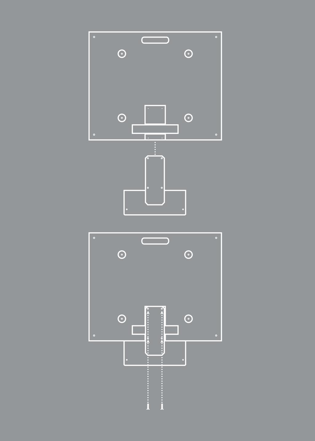
10 P9 MOUNT YOUR FOOT PLATE The ELITE footplate comes with 4 pre-drilled holes on the underside to securely mount the test stand pole to the footplate. Step 1. Lay the test stand pole on its back with the footplate mounting bracket pointing upwards. Step 2. Mount the footplate to the test stand pole using 4 A screws into the underside of the footplate.
11 P10 A A
12 WIRING YOUR FOOT PLATE Once you have completed the previous section (Mount Your Footplate): Step 1. Feed the RJ45 Cable and DC Output from the Power Supply through the bottom rear opening of the Test Stand Pole. Pull the cables through the pole and out the top rear opening. Step 2. Connect the RJ45 Cable and Ground Cord to the footplate. Step 3. Connect the ring terminal of the Ground Cord to a known good ground. Step 4. Connect the DC Output and RJ45 Cable into the bottom of the ELITE tester. Step 5. Connect the Power Supply into a 120V AC outlet. P11
13 P12
14 P13 CONNECT TO YOUR NETWORK Follow the diagram for the best suited network connection type. A Direct USB Connection - Firmware Updating Connect from the ELITE using the USB cable to an available USB port on a PC. B Direct Ethernet Connection - Data Communications Connect from the ELITE using the Ethernet cable to an available Ethernet port on a PC. C Ethernet Network Connection - Data Communications Connect from the ELITE using the Ethernet cable to an available Ethernet port on a router.
15 P14 A B C
16 CONNECT TO YOUR RELAYS P15 There are two relays, A & B, on the bottom of the ELITE Tester. Each relay has 3 inputs; Normally Open (NO), Common (C), and Normally Closed (NC). How you wire to your ELITE depends on the type of switch on your external device. Once you have determined the type of switch, follow the illustration for connection procedure. A is triggered on an entry event (passing test result), acting as a switch to control outside gates, such as doors, light towers, and turnstiles upon a passing test result. B is commonly used for exiting, when access is controlled by the ELITE Test System. It works in conjunction with external I/O devices connected to the tester such as ID readers and IR exit switches. B can also be set to mirror Relay A and switch a second device upon an entry event.
17 P16
18 AN IMPORTANT NOTE Please read this document and check that your system is set up carefully before you first use your ELITE Test System. LEARN MORE You can find more information and learn even more about ELITE features at SUPPORT Your ELITE comes with 90 days of technical support and one year of hardware repair warranty coverage. For more information please contact: Phone: MAILING Botron Company Inc N. 21st Avenue Phoenix, AZ All rights reserved. Designed by Botron.
19 ELITE Test Systems 02 /Quick Start Web UI Botron Company Inc.
20 YOUR ELITE V2 WEB UI P1 Welcome to the ELITE V2 Web UI. Here you can control the settings of your device such as VTR (Variable Test Resistance) Technology, calibration, relays and much more. The ELITE V2 Web UI is an interactive web app that works in most browsers across many platforms, such as mobile phones, tablets and desktops. This gives you access to your test equipment anywhere you go within your network. Once you have connected your device to your network, access the Web UI by entering the IP address in the browser of your choice. The IP address is automatically obtained by the ELITE V2 once connected to your network. This Quick Start Guide is to give you an overview of the screens and features of the Web UI.

21 P2 GETTING STARTED Please check that your Ethernet cable is securely connected to the ELITE. If you need assistance on connecting your device to your network please refer to Quick Start Guide 01 - Wiring & Mounting. To find your IP address, hold down the # key on the keypad, please wait for it to beep again and release. This will bring you into the TCP/IP information screen, here you can see the device network information, including the IP address. Record the IP address and enter it into your internet browser URL bar. The ELITE Web UI works with internet browsers across mobile devices and desktops. Look for Tooltips on the Web UI screens for a more detailed explanation on each feature.
 as each user inputs their ID.")
22 P3 LIVE VIEW The Live View screen displays realtime information about the personnel interacting with the equipment. There are 3 tiles: User, Result and Devices. The User information tile will update the ID number, Name, Protocol (Test Requirement) as each user inputs their ID. The Result tile will light up PASS in Green, or FAIL in Red depending on the test outcome. The Device tile is also interactive. Grayed out icons will change to either Green, Red, or Yellow depending on the test result. It also displays the resistance value for each device.
23 P4 UNIT TAG The Unit Tag page is where you can name your device. If you have multiple ELITE Testers or your lab areas are tagged internally, use the provided fields to help identify your testers location. The description field can be filled out to further help identify the device, especially if grouped with other testers in the same location.

24 P5 TEST SETTINGS VTR (Variable Test Resistance) Technology gives you all the control and customization over your test settings. In this screen you can set the Low and High Fail as well as our unique and powerful Near Failure adjustment for Wrist Strap, Smock/Garment, and Footwear. You will also notice that you can toggle display and auto detection on/off for each device. Device Titles: Adjust the High, Low, and Near Fail settings of each device (in Ohms). Test Configuration: Control various timing controls and configure how a test is performed. Dual Wire Select: The Dual Wire jack on the ELITE works with either a Wrist Strap or Smock/Garment. You can select either of these options or disable the jack input.

25 P6 RFID Completely unique to only ELITE Complete Test Systems, you can decode up to 4 RFID bit rate types directly on your ELITE Test System. RFID Decode Tool: To enter RFID Decode Mode select Decode Card. Recommended Card Settings: This will populate with the card data you will need to input in the RFID Decode tile. RFID Decode: This tile is where you enter the information from the Recommended Card Settings tile.
26 P7 BARCODE SETTINGS For those with barcode type IDs, in this tab you can control what information the scanner needs to read. In some cases, a barcode may start and/or end with characters not prudent to the ID number itself. Barcode ID start position: This is where the scanner begins reading the characters of the Barcode. Barcode ID length: This is how many characters of the string from the start position the scanner will read. Keypad Enable: Enable/Disables keypad ID input.

27 P8 CALIBRATION All calibration information is time stamped and stored digitally on your test system. Your calibration certificate is easily accessible though this screen in the web app when you need it. All Elite Test Systems come calibrated from the factory.
28 P9 NETWORK When connected to a PC by the Ethernet cable, the ELITE Tester will configure it s Local Area Network (LAN) settings. Assuming you are on the network, this screen will have stored all the network information regarding this device. When Dynamic Host Configuration Protocol is enabled the ELITE Tester's network settings will be assigned by the network router. By disabling DHCP, you may manually configure the ELITE Tester's network settings.
29 P10 FACTORY DEFAULT In this screen you can choose to reset individual settings back to a factory default.
30 AN IMPORTANT NOTE Please read this document and check that your system is set up carefully before you first use your ELITE Test System. LEARN MORE You can find more information and learn even more about ELITE features at SUPPORT Your ELITE comes with 90 days of technical support and one year of hardware repair warranty coverage. For more information please contact: Phone: MAILING Botron Company Inc N. 21st Avenue Phoenix, AZ All rights reserved. Designed by Botron.
Ohm Metrics. Instruction Manual. Dual Footwear Wrist Strap Tester Model PDT800K
 T R A N S F O R M I N G T E C H N O L O G I E S, L L C O U T S T A N D I N G A L T E R N A T I V E S I N S T A T I C C O N T R O L Ohm Metrics Dual Footwear Wrist Strap Tester Model PDT800K Instruction
Table of Contents. The Botron B92700 OMNIGND is a Multi-Ground Continuous Monitoring Automation System.
 Operation Manual Table of Contents Description: The Botron B92700 OMNIGND is a Multi-Ground Continuous Monitoring Automation System. Directory: Overview Pg. 2 Features Pg. 3 Quick Setup Guide Pg. 3 Settings
T R A N S F O R M I N G T E C H N O L O G I E S, L L C O U T S T A N D I N G A L T E R N A T I V E S I N S T A T I C C O N T R O L
 T R A N S F O R M I N G T E C H N O L O G I E S, L L C O U T S T A N D I N G A L T E R N A T I V E S I N S T A T I C C O N T R O L Ohm Metrics Combonation Wrist Strap & Footwear Tester Model PDT700 Instruction
Product Overview. System Overview
 Product Overview The ESDMAN 6809 ESD Access Control System is designed for fast, frequent, and accurate testing of ESD personnel grounding items. Its unique design embeds an ESD tester, computer clock,
ESD Monitoring, Ionization & Test. SmartLog V5. ESD Data Acquisition System. Rev Made in United States of America.
 EMIT ESD Monitoring, Ionization & Test SmartLog V5 ESD Data Acquisition System Rev. 2013-05 Features and Benefits The patented* EMIT SmartLog V5 is designed for fast, frequent, and accurate testing of
EAP110-Outdoor. Installation Guide. 300Mbps Wireless N Outdoor Access Point
 EAP110-Outdoor Installation Guide 300Mbps Wireless N Outdoor Access Point Contents Overview 1 Typical Network Topology 4 Lightning and ESD Protection 5 Hardware Installation Mount EAP Connect Cables Power
T R A N S F O R M I N G T E C H N O L O G I E S, L L C O U T S T A N D I N G A L T E R N A T I V E S I N S T A T I C C O N T R O L
 T R A N S F O R M I N G T E C H N O L O G I E S, L L C O U T S T A N D I N G A L T E R N A T I V E S I N S T A T I C C O N T R O L Ohm Metrics Wrist Strap & Footwear Combination Tester GTS600 Instruction
CAP300-Outdoor. Installation Guide. 300Mbps Wireless N Outdoor Access Point
 CAP300-Outdoor Installation Guide 300Mbps Wireless N Outdoor Access Point Contents Overview 1 Typical Network Topology 4 Lightning and ESD Protection 5 Hardware Installation Mount CAP Connect Cables Power
WELCOME. For customer support or any inquiries, please visit our web site at or contact us at
 WELCOME Congratulations on purchasing the GBF Smart Four Wire Intercom System. Our factory engineers were the first to enable multiple security cameras being monitored through a smart mobile device and
RangerBOSS Network Ready Constant Monitor Model CM2800
 RangerBOSS Network Ready Constant Monitor Model CM2800 Instruction Manual Contents 1 Description CM2800 1 Features 1 2 Installation Installation Instructions 2 Installation Diagram 3 3 Operation Wrist
PGT 120. Personnel Grounding Tester. Wrist Strap and Footwear Tester. Users's Manual
 PGT 120 Personnel Grounding Tester Wrist Strap and Footwear Tester Users's Manual 1 Table of contents 1 TABLE OF CONTENTS... 2 2 INTRODUCTION... 3 2.1 Device return and environmentally compatible disposal...
A TCP/IP network CAT 5 cable If the network is faster than 10baseT a switching hub will be needed Static IP address
 Requirements A TCP/IP network CAT 5 cable If the network is faster than 10baseT a switching hub will be needed Static IP address Power Up A Reader with an Ethernet adaptor installed and the network cable
Welcome Contents Diagram
 Welcome Congratulations on your purchase of our GBF PL960 Series of IP Doorbells. Our factory engineers were the first to enable viewing of multiple security cameras through your handheld smart device,
210 SERIES WEBSMART NETWORK SWITCHES Quick Start Guide AN-210-SW-F/R-8-POE AN-210-SW-F/R-16-POE AN-210-SW-F/R-24-POE AN-210-SW-F-48-POE
 210 SERIES WEBSMART NETWORK SWITCHES AN-210-SW-F/R-8-POE AN-210-SW-F/R-16-POE AN-210-SW-F/R-24-POE AN-210-SW-F-48-POE Araknis Networks 210 Series Websmart Network Switches FCC Warning Changes or modifications
VDSL Router 4 Port Wi-Fi Dual Band (NT3BB-4PVWN-147) Quick Installation Guide
 Quick Installation Guide") VDSL Router 4 Port Wi-Fi Dual Band (NT3BB-4PVWN-147) Quick Installation Guide 1. Packing List The following table lists the items in the product package. Item Quantity VDSL Router 1 Power Adapter 1 RJ
VDSL Router 4 Port Wi-Fi Dual Band (NT3BB-4PVWN-147) Quick Installation Guide 1. Packing List The following table lists the items in the product package. Item Quantity VDSL Router 1 Power Adapter 1 RJ
1 Hardware Installation
 1 Hardware Installation 1.1 Choosing the Best Location for Wireless Operation Many environmental factors may affect the effective wireless function of the DSL Router. If this is the first time that you
EZ-TAG2 Manual_Layout 5 11/12/ :14 Page 1 U S E R M A N UAL
 EZ-TAG2 Manual_Layout 5 11/12/2012 09:14 Page 1 USER MANUAL EZ-TAG2 Manual_Layout 5 11/12/2012 09:14 Page 2 Contents EZ-TAG2 and Back Plate 1 x Security Torx Key 4 x Screws and raw plugs 1 x Marking out
Finger Vein Access Control device Quick Start Guide Version: 1.0 Date: June USB slot. USB slot
 Overview Fingerprint & Finger Vein Device Front Left Side: Finger Vein Device Touch screen Card reader Fingerprint reader Finger vein reader Finger vein sensor: During registration, after finger touches
310 SERIES LAYER 2 MANAGED NETWORK SWITCHES Quick Start Guide
 310 SERIES LAYER 2 MANAGED NETWORK SWITCHES AN-310-SW-F/R-8 AN-310-SW-F/R-16 AN-310-SW-F/R-24 AN-310-SW-F/R-8-POE AN-310-SW-F/R-16-POE AN-310-SW-F/R-24-POE FCC Warning Changes or modifications not expressly
SAMi Installation Instructions
 SAMi Installation Instructions Unpack the camera. Leave the clear plastic protective film on until after the camera is installed as it is easy to scratch the lens. For the initial setup you need to connect
Operation and Maintenance Manual
 VM Series Operation and Maintenance Manual VM - Voltage Monitor VM-100-24 V VM-100-48 V VM-100-125 V VM-100-250 V EAGLE EYE POWER SOLUTIONS All Rights Reserved. 1 The Voltage Monitor series reads battery
Quick Start Guide. ProBio & ProFAC + ZKBioSecurity 3.0
 Quick Start Guide ProBio & ProFAC + ZKBioSecurity 3.0 CONTENT 1 Safety Precautions...2 On Using Face Recognition Device...3 Device Overview...5 Product Dimensions & Installation...6 Power Connection...7
Warnings & Guidelines:
 Please read the following instructions and warnings carefully. Keep this instruction manual for future reference. Tools required (for wall mouting Camera only): Screwdriver and Drill (not included) For
Zavio P5111/ P5116/ P5210 Quick Installation Guide
 86085M2000010 Zavio P5111/ P5116/ P5210 Quick Installation Guide Installation Steps Please follow the installation steps below to set up your P5111 / P5116/ P5210 Day/Night Pan/Tilt IP Camera. Check the
HUAWEI FT2260 Home Phone Connect Quick Start
 HUAWEI FT2260 Home Phone Connect Quick Start Introduction Top View The figures are only for your reference, the actual shape and color of the product may differ slightly. 7 8 9 10 1 2 3 4 5 6 1 Power on/off
QUICK START GUIDE. 2.4 Inch TFT Terminal Time Attendance & Access Control
 QUICK START GUIDE 2.4 Inch TFT Terminal Time Attendance & Access Control Safety Precautions The following precautions are to keep user safe and prevent any damage. Please read carefully before installation.
PoE/FPR Kit for Auto-Sync Time Clock. The Auto-Sync Time Clock is a validated time system with a Web interface and auto discovery.
 ASTCPOEK PoE/FPR Kit for Auto-Sync Time Clock The Auto-Sync Time Clock is a validated time system with a Web interface and auto discovery. The ASTCPOEK Kit provides Power over Ethernet with Full Power
300 Series Mini Bullet IP-Enabled HD Surveillance Camera. Installation Manual. Important! Ensure your NVR has the latest firmware!
 300 Series Mini Bullet IP-Enabled HD Surveillance Camera Installation Manual Important! Ensure your NVR has the latest firmware! Read this before you go on site! For maximum control and convenience, install
Floor Standing Pedestal
 2336 K052 Floor Standing Pedestal Kit Instructions Issue C Revision Record Issue Date Remarks A Feb 20021 First issue B June 2007 Added pedestal floor bolting procedure C Mar 2011 Added Universal Mounting
PIX 515/515E. PIX 515/515E Product Overview CHAPTER
 CHAPTER 4 PIX 515/515E This chapter describes how to install the PIX 515/515E, and includes the following sections: PIX 515/515E Product Overview Installing a PIX 515/515E PIX 515/515E Feature Licenses
SF200. Installation Guide & Quick Start Guide. 2 TFT AC Terminal Version: 1.0 Date: June 2014
 SF200 Installation Guide & Quick Start Guide 2 TFT AC Terminal Version: 1.0 Date: June 2014 All design and specification declared are subject to change without notice in advance. Contents Safety Precautions
Quick start guide for i5 520 ( or )
") Quick start guide for i5 520 (9405-520 or 9406-520) 1 Before you begin This Quick start guide contains an abbreviated set of setup instructions designed to help you quickly unpack and set up a standard
Quick start guide for i5 520 (9405-520 or 9406-520) 1 Before you begin This Quick start guide contains an abbreviated set of setup instructions designed to help you quickly unpack and set up a standard
Installation & User Manual
 Contents Installation Instructions 3 Installation Diagrams 4 System Overview 6 Wiring Diagrams 8 Network Diagrams 9 Operation Instructions Fingerprint Enrollment 12 21 Wi-Enterprise Controller www.transmittersolutionssmart.com
Installing Keypad and Backplate
 Installing Keypad and Backplate Fig.1 Positioning of Fixing Holes and Cable Outlet Cable Outlet, Drill Diameter 10mm for Cable Access Remove the back plate, which is fitted to rear of the keypad, using
M101M4 Tablet PC Quick Start Guide V1.0
 M101M4 Tablet PC Quick Start Guide V1.0 Please read these instructions carefully before using this product, and save this manual for future use. Getting Started Congratulations on purchasing this rugged
Atlas S8+ Product Manual. Version Promise Technology, Inc. All Rights Reserved.
 Atlas S8+ Product Manual Version 1.0 2018 Promise Technology, Inc. All Rights Reserved. Promise Technology Atlas S8+ Copyright 2018 PROMISE Technology, Inc. All Rights Reserved. Important data protection
EWS660AP. Quick Installation Guide
 Package contents - Managed indoor access point - Power adapter - RJ-45 Ethernet cable - Mounting bracket - Mounting kit - T-Rail mounting kit IP Adress configuration Step 1: Once your computer is on, ensure
MultiConnect Adapters
 MultiConnect Adapters Serial-to-Serial Adapter Serial-to-Ethernet Adapter Quick Start Guide 2 Multi-Tech Systems, Inc. Quick Start Guide Introduction This guide shows you how to setup your MultiConnect
8 Button IP Controller Installation and Operation Manual AV-IP-C8-WH
 8 Button IP Controller Installation and Operation Manual AV-IP-C8-WH West Penn Wire 2018 94-000880-A / SE-000880-A Page 1 / 20 Introduction The 8 Button IP Controller (Model: AV-IP-C8-WH) is a versatile
Allworx 24x Service and Troubleshooting Guide
 Allworx 24x Service and Troubleshooting Guide -PAGE INTENTIALLY LEFT BLANK- Table of Contents 1 Safety Instructions...1 1.1 Electrical...1 1.2 Electrostatic Discharge...1 2 Chassis Views...2 3 Exterior
2017 TigerStop, LLC. uid. TigerSPC. ation G. talllat. tal. Ins. February 2017 Mk1
 IIn Ins ns talllat uid ns stallation tal ation G Guide ui u iid de 2017 TigerStop, LLC TigerSC February 2017 Mk1 1 Serial Number TigerSC Standard Jaws Antenna Bench Mount Brackets Wireless Receiver ower
2M Outdoor Motorized Bullet Camera
 2M Outdoor Motorized Bullet Camera 8608586000010 Quick Installation Guide Please follow the installation steps below to set up your 2MP Bullet IP Camera. Check the package contents against the list below.
W Series. Color Screen Fingerprint & Card Time Attendance and Access Control W 1 W 2
 W Series Color Screen Fingerprint & Card Time Attendance and Access Control W 1 W 2 W1 & W2 Features * Standard 2.8-inch TFT LCD, 512MB Flash, industrial high speed CPU * Touch keypad & touch active sensor
Copy Machine Reader. Installation and Setup Guide
 Copy Machine Reader Installation and Setup Guide CONTENTS 1 COPY MACHINE READER INSTALLATION 1 Overview 1 Reader Specifications 3 CR1120/CR1122 INSTALLATION 3 Copier Interface 3 AC Electrical 3 Communications
VE8012A/VE8012AR DUAL NETWORKED STATION PORT
 ISSUE 3 VE8012A/VE8012AR DUAL NETWORKED STATION PORT INTRODUCTION The VE8012A/VE8012AR Dual Networked Station Port allows most loop start terminal devices to be connected to a managed IP-based LAN/WAN.
Installation & User Manual V2.08
 YOUR SECURITY IS OUR PRIORITY Other products from GSD Contents Installation Instructions Installation Diagrams System Overview Wiring Diagrams Network Diagrams Operation Instructions Fingerprint Enrollment
Installation Instructions
 Installation Instructions Model: EEEA121A SIS-910 New York Service / Inspection System Analyzer Setup Page: 1 of 7 INSTALLATION MUST BE PERFORMED BY QUALIFIED EQUISERV PERSONNEL ONLY INSTALLATION OVERVIEW:
Part # Quick-Start Guide. SpeedStream 4200 Modem PPPoE Modem Router
 Part # 007-0-00 Quick-Start Guide SpeedStream 00 Modem PPPoE Modem Router Before you begin, Verify that the following items came with your DSL kit: Step > Install Line Filters 7 SpeedStream Device Documentation
21 TRACK MAINTENANCE GUIDE
 Mountain Engineering II, Inc. 21 TRACK MAINTENANCE GUIDE 1233 Sherman Drive, Longmont, CO 80501-6133 303-651-0277 303-651-6371 (fax) www.mountainengineering.com Table of contents Table of contents...2
Table of Contents. Unpacking and Inspection Setup Loading the Media Mount the Printer on the Wall... 16
 WPL25/WHC25 Table of Contents Unpacking and Inspection... 1 Setup... 5 Loading the Media... 6 Mount the Printer on the Wall... 16 LED and Button Functions... 17 Troubleshooting... 18 Unpacking and Inspection
Active Club POS Hardware Setup
 Active Club POS Hardware Setup The Active Club POS hardware package includes the following (see figure 1): Heckler stand for ipad APG Vasario 1616 cash drawer Connecting cable for cash drawer Star Micronics
Revision History E F G H J K Revision Description: K > Allegion Rebranding.
 Notes: Enter any notes here. These notes must include: how many sides of the paper are printed ink color (usually black, may also be one or two specific colors, such as a Pantone value, or 17.000 8.500
NISTA DEVICES GmbH 2013 All Rights Reserved. Door Access Control with the VoIP interface IP epcr Release 1.02
 NISTA DEICES GmbH 2013 All Rights Reserved Door Access Control with the oip interface IP 39-60 epcr Release 1.02 1 NISTA DEICES GmbH 2013 All Rights Reserved IP Door Phones IP 39-60ePCR Quick Installation
SVT-WIFI Video Intercom System C
 SVT-WIFI Video Intercom System C User Manual Please read this user manual prior to installing the system, and keep it well for future use. CONTENTS 1. Parts and Functions... 1 2. Terminal Descriptions...
AX3000 Platine Terminal Ethernet TCP/IP
 AX3000 Platine Terminal Ethernet TCP/IP Model 80 Installation Guide January 2012 - Ref: I80E0922-2 Model AX3000/M80 Type EA The reproduction of this material, in part or whole, is strictly prohibited.
Roughneck V920D Series Camera Domes XX Quick Guide
 Quick Guide XX258-20-06 Roughneck V920D Series Camera Domes Vicon Industries Inc. Tel: 631-952-2288 Fax: 631-951-2288 Toll Free: 800-645-9116 24-Hour Technical Support: 800-34-VICON (800-348-4266) UK:
CP150B Vandal & Weather Resistant Keypad Security Systems
 Vandal & Weather Resistant Keypad Security Systems EN Security System CP150B - Vandal & Weather Resistant Keypad The CP150B keypad provides alarm and or access control functionality when used on selected
Ethernet/Network Communications Module. Installation and Programming Manual. LINQ2 - Two (2) Port Connectivity Module. More than just power.
 Port Connectivity Module. More than just power.") Ethernet/Network Communications Module Installation and Programming Manual LINQ2 - Two (2) Port Connectivity Module DOC#: LINQ2 Rev. 060514 More than just power. Overview: Altronix LINQ2 network module
Ethernet/Network Communications Module Installation and Programming Manual LINQ2 - Two (2) Port Connectivity Module DOC#: LINQ2 Rev. 060514 More than just power. Overview: Altronix LINQ2 network module
Cisco SRP500 Series Services Ready Platforms (SRP540 Models)
") Quick Start Guide Cisco SRP500 Series Services Ready Platforms (SRP540 Models) Package Contents Cisco SRP500 Series (with detachable WiFi antennas) RJ-45 Ethernet Cable RJ-11 Telephone Cable Power Cord
Quick Start Guide Cisco SRP500 Series Services Ready Platforms (SRP540 Models) Package Contents Cisco SRP500 Series (with detachable WiFi antennas) RJ-45 Ethernet Cable RJ-11 Telephone Cable Power Cord
ReachFree ID Installation Instructions for Wash Select II. Unitec
 ReachFree ID Installation Instructions for Wash Select II Unitec www.startwithunitec.com Proprietary Information and Materials of Unitec Inc. Such proprietary information and materials may not be disclosed
OUTPUT COM AUDIO R RS-232 RESET. Tx Rx G
 ShareLink Pro 000 Setup Guide This guide provides instructions for installing and connecting the Extron ShareLink Pro 000 Collaboration Gateway. The ShareLink Pro 000 allows anyone to present wireless
Installation Instructions
 ENGAGE INFLUENCE OPTIMIZE Installation Instructions Fast Track SA Drive Thru Timing System Effective Date: November 1, 2017 Fast Track SA Installation Instructions Page 2 of 28 Table of Contents 1 INTRODUCTION...
Secured Series: Hub Plus Kit Single Door Controller Package Installation Manual
 Secured Series: Hub Plus Kit Single Door Controller Package Installation Manual This package is designed to simplify the connections to our Secured Series Hub Plus Controller. This will translate into
Dual-Band Wireless A + G Access Point. Network Layout
 Network Layout The Dual-Band Wireless A + G Access Point has been designed for use with 802.11g and 802.11b products. With 802.11g products communicating with the 802.11b standard, products using these
User s Guide. Ethernet Module for Barcode Printer
 User s Guide Ethernet Module for Barcode Printer 1. ETHERNET MODULE... 2 1-1. Functions... 2 1-2. General Specifications... 2 2. ETHERNET MODULE INSTALLATION... 3 2-1. Ethernet Module Installation for
50440/50441 SmartLog X 3
 50440/50441 SmartLog X 3 Wrist Strap and Footwear Tester Automated ESD Record Keeping Personal Grounding Verifier with Data Transmission Hardware & Software Setup Instructions 3651 Walnut Avenue, Chino,
NetCommWireless. Quick Start Guide NTC-30 Series - Outdoor WiFi Router
 NetCommWireless Quick Start Guide NTC-30 Series - Outdoor WiFi Router NetCommWireless Let s get this show on the road You must be excited to get started with your Outdoor WiFi Router. If all goes to plan,
IBM Systems. Quick start guide for IBM System p5 505 ( )
") IBM Systems Quick start guide for IBM System p5 505 (9115-505) 1 Before you begin This Quick start guide contains an abbreviated set of setup instructions designed to help you quickly unpack and set up
IBM Systems Quick start guide for IBM System p5 505 (9115-505) 1 Before you begin This Quick start guide contains an abbreviated set of setup instructions designed to help you quickly unpack and set up
Quick Installation Guide
 Quick Installation Guide WAP-EN1750C AC1750 Ceiling Mount Access Point I. I Product Information I-1. Package Contents 1 2 5 6 3 4 7 1. Access Point 5. Quick Installation Guide 2. Ceiling Mount Bracket
MARQUE : REFERENCE : CODIC : NETGEAR GSS108E-100EUS NOTICE
 MARQUE : REFERENCE : CODIC : NETGEAR GSS108E-100EUS 4254961 NOTICE ProSAFE 8-Port and 16-Port Gigabit Web Managed Click Switch Model GSS108E and GSS116E User Manual May 2016 202-11520-03 350 East Plumeria
Zero Volt Monitor Installation, Operation and Maintenance
 TECHNICAL BULLETIN TB-6515 Zero Volt Monitor Installation, Operation and Maintenance Made in the United States of America strap properly, the monitor measures the loop resistance consisting of one wire
4. We recommend that you install the ievo reader at the DDA height of approximately 1 metre. This will be the perfect height for finger placement.
 WELCOME ievo would like to thank you for purchasing our product. This manual is designed to make your installation of our superior biometric reader quick, easy and efficient. Please ensure you check all
Part # Quick-Start Guide. SpeedStream Residential Gateway 5450 Four-Port Router
 Part # 007-6560-001 Quick-Start Guide SpeedStream Residential Gateway 5450 Four-Port Router Before you begin, Verify that the following items came with your DSL kit: 1 SpeedStream Device 2 Documentation
8/16/32-Ch Network Video Recorder NVR Series
 8/16/32-Ch Network Video Recorder NVR Series Quick Installation Guide Table of Contents Chapter 1. Introduction...3 1.1 Before Installation...3 Chapter 2. Physical Description and Installation...4 2.1
SIP IP VIDEO DOOR PHONE.
 SIP IP VIDEO DOOR PHONE www.avadesign.com.tw WELCOME Congratulations on purchasing the V-Bell DP-104 SIP IP Video Door Phone. This door phone is suitable for all your business, and home, door entry communication
HSPA+ WiFi Router with Voice
 NETCOMM LIBERTY SERIES HSPA+ WiFi Router with Voice 3G22WV Quick Start Guide This router has been designed to be placed on a desktop. All of the cables exit from the rear for better organization. The LED
F3102 / F3107 / F3110 / F3115 / F3210 / F3215 PN: 86085K K
 F3102 / F3107 / F3110 / F3115 / F3210 / F3215 0 86085K3000020 PN: 86085K3000020 Zavio F3102/F3107/F3110/F3115/F3210/F3215 Quick Installation Guide Please follow the installation steps below to set up
VC 220 Dome WDR Day/Night PoE Network Camera
 Quick Start Guide Cisco Small Business VC 220 Dome WDR Day/Night PoE Network Camera Package Contents Cisco VC 220 Network Camera Power Adapter Two L-Shaped Audio Cables Mounting and Installation Accessories
Amano (itrt) Intelligent Twin Reader Terminal INSTALLATION MANUAL
 Intelligent Twin Reader Terminal INSTALLATION MANUAL") MODEL NUMBER: XRT910-0-0-AC-XX XRT920-0-0-AC-XX AMANO itrt Amano (itrt) Intelligent Twin Reader Terminal INSTALLATION MANUAL SPECIFICATIONS Working Environment Plastic Housing... Power Designed to work
MODEL NUMBER: XRT910-0-0-AC-XX XRT920-0-0-AC-XX AMANO itrt Amano (itrt) Intelligent Twin Reader Terminal INSTALLATION MANUAL SPECIFICATIONS Working Environment Plastic Housing... Power Designed to work
2017 TigerStop,LLC. Printer. February 2017 Mk1
 2017 TigerStop,LLC Printer 1 February 2017 Mk1 Printer Power Supply Power Cable I/O Panel w/ Cable RS232 Cable Printer Stand Optional 2 Tablet Package (Loaded with TigerPrint Display) Safety First! IMPORTANT
Print Server. User s Manual. Rev. 01 (April, 2004) Made In Taiwan
 Made In Taiwan") Print Server User s Manual Rev. 01 (April, 2004) Made In Taiwan TABLE OF CONTENTS ABOUT THIS GUIDE... 4 INTRODUCTION... 5 PACKAGE CONTENTS... 6 SYSTEM REQUIREMENTS... 6 GENERAL FEATURES... 7 PRODUCT VIEW...
Print Server User s Manual Rev. 01 (April, 2004) Made In Taiwan TABLE OF CONTENTS ABOUT THIS GUIDE... 4 INTRODUCTION... 5 PACKAGE CONTENTS... 6 SYSTEM REQUIREMENTS... 6 GENERAL FEATURES... 7 PRODUCT VIEW...
RC-SV Configuration Guide Revision 3
 Kramer Electronics, Ltd. RC-SV Configuration Guide Revision 3 Software Version 2.1.2.32 Intended for Kramer Technical Personnel or external System Integrators. To check that you have the latest version,
Zavio F3100 / F3105 Quick Installation Guide
 Zavio F3100 / F3105 Quick Installation Guide Please follow the installation steps below to set up F3100 / F3105 IP Camera. Check the package contents against the list below. See P.1 Physical overview.
INSTALL & SET-UP GUIDE
 Wall Sockets Featuring WIFI EXTEND (SSID REPEAT) POWERLINE TECHNOLOGY USB CHARGING INSTALL & SET-UP GUIDE THIS INSTALL GUIDE IS FOR: WiFi CONNEkT Starter Kit and WiFi CONNEkT Add-On Sockets GROUP GEAR
MODEL KP-100 ACCESS CONTROL DIGITAL KEYPAD OPERATING INSTRUCTIONS
 MODEL KP-100 ACCESS CONTROL DIGITAL KEYPAD OPERATING INSTRUCTIONS Model KP-100 is a self-contained digital keypad. This keypad is suitable for residential, industrial, and commercial installations. It
Access control panel U-Prox IC E (Elevator control)
") 1.003 Access control panel U-Prox IC E (Elevator control) Installation and programming manual About this document http://u-prox.com This manual covers installation, adjustment and use of U-Prox IC E (hereinafter
1.003 Access control panel U-Prox IC E (Elevator control) Installation and programming manual About this document http://u-prox.com This manual covers installation, adjustment and use of U-Prox IC E (hereinafter
AerMonitor AM Aer Monitor User's Manual. Version-0.1
 AerMonitor AM-1015 Aer Monitor User's Manual Version-0.1 AerMonitor AM-1015 Copyright Notice This document is copyrighted, 2013. All rights are reserved. Firich Enterprise Co., Ltd reserves the right to
Plus-X 300. Installation and Operation Manual
 Plus-X 300 Installation and Operation Manual Table of Contents Introduction... 1 Compatibility... 1 Installation... 1 Configuration... 2 Operation... 5 Getting Help... 6 Warranty... 6 Appendix A: Specifications...
Digital Keypad Introduction
 K2 Digital Keypad Introduction The K02 uses the latest microprocessor technology to operate door strikes and security systems that require a momentary (timed) or latching dry contact closure. All programming
300 Series Cube Wireless HD Surveillance Camera with Microphone. Installation Manual. Important! Ensure your NVR has the latest firmware!
 300 Series Cube Wireless HD Surveillance Camera with Microphone Installation Manual Important! Ensure your NVR has the latest firmware! Read this page before you go to the job site! 2 For maximum control
Nighthawk AC1750 Smart WiFi Router User Manual
 Nighthawk AC1750 Smart WiFi Router User Manual Model R6700v3 February 2018 202-11830-01 350 E. Plumeria Drive San Jose, CA 95134 USA Support Thank you for purchasing this NETGEAR product. You can visit
Steady green On hook. Slow flashing green Off hook. Off Port not ready. Off No link. Fast flashing green Upgrading firmware.
 Product Features Product Features Top Panel Feature Description Steady green On hook. Phone Phone 2 Slow flashing green Off hook. Off Port not ready. Flashing green Transmitting or receiving data through
Emergency Dialer DIAL-ALERT MODEL: ED
 www.skylinkhome.com Emergency Dialer TM DIAL-ALERT MODEL: ED-100 101A083-002 FEB, 2006. CUSTOMER SERVICE 17 Sheard Avenue, Brampton, Ontario, Canada L6Y 1J3 Tel : (905) 456-8883 Fax : (905) 456-7819 Email
Lab: Install a NIC in Windows XP
 11.4.1 Lab: Install a NIC in Windows XP Introduction Print and complete this lab. In this lab, you will install a NIC, verify NIC operation, and manually configure an IP address. Recommended Equipment
Wiring Instructions v4
 Wiring Instructions v4 GateKeeper h4.2 Technical Support support@gymmastersoftware.com USA: 415 678 1270 Australia: 03 9111 0323 : 03 974 9169 Copyright 2018 Treshna Enterprises. All rights reserved. 15
Installation & Setup Guide
 Declare your energy independence. Installation & Setup Guide The following guide details the steps and procedures to properly install and commission a JLM Phazr system. If you require assistance during
Quick start guide for p5 520 ( )
") Quick start guide for p5 520 (9111-520) 1 Before you begin This Quick start guide contains an abbreviated set of setup instructions designed to help you quickly unpack and set up a standard system. Users
Quick start guide for p5 520 (9111-520) 1 Before you begin This Quick start guide contains an abbreviated set of setup instructions designed to help you quickly unpack and set up a standard system. Users
Quick Installation Guide of Acer WLAN 11b Broadband Router
 Preparation 1 At lease one PC with IEEE802.11b WLAN client installed. 2 One straight-through Category 5 Ethernet cable, used to link WAN interface to xdsl or CM for Internet connection. 3 Acer WLAN 11b
F3102 / F3107 / F3110 / F3115 / F3210 / F3215 PN: 86085K K
 F3102 / F3107 / F3110 / F3115 / F3210 / F3215 86085K3000020 PN: 86085K3000030 Zavio F3102/F3107/F3110/F3115/F3210/F3215 Quick Installation Guide Please follow the installation steps below to set up F3102
Moving-Minds.com Treadmill Desk Operation
 LifeSpan Treadmill Desk - Owner s Manual Models DT-5/DT-7 Desk Assembly DT-5 Desk........................................................................................ Assembly Instructions..........................................................................