Glide Wall Mount, LD-X User's Guide
|
|
|
- Denis Bryant
- 5 years ago
- Views:
Transcription
1 Glide Wall Mount, LD-X User's Guide Screen Capacity Lift Tilt Pan Rotation VESA lbs ( kg) 10 (25.4mm) TV/Display 10 TV/Display 95 Extension 180 Yes 100 x x x x x x User's Guide - English Guía del usuario - Español Manuel de l utilisateur - Français Gebruikersgids - Nederlands Benutzerhandbuch - Deutsch Guida per l utente - Italiano Användarhandbok - svenska : Table of Contents TV/Display Specifi cations Safety Hazard Symbol Review Components Tools Determine mounting location Mount Glide to wall: Option A: wood stud walls Option B: solid concrete walls Attach TV/Display to Glide Option A: no VESA adapter needed Option B, C, D: with VESA adapters Quick Release Route Cables Test Range of Motion Adjust according to applied load and desired user force of 15
2 Hazard Symbols Review These symbols alert users of a safety condition that demands attention. All users should be able to recognize and understand the signifi cance of the following Safety Hazards if encountered on the product or within the documentation. Children who are not able to recognize and respond appropriately to Safety Alerts should not use this product without adult supervision! Symbol Signal Word Level of Hazard NOTE CAUTION WARNING ELECTRICAL A NOTE indicates important information that helps you make better use of this product. A CAUTION indicates either potential damage to hardware or loss of data and tells you how to avoid the problem. A WARNING indicates either potential for property damage, personal injury, or death. An Electrical indicates an impending electrical hazard which, if not avoided, may result in personal injury, fire and/or death. Components 1x 1x 2x 2x M6 x 70mm M8 anchor 8x M4 x 6mm M4 x 15mm M4 x 30mm M5x 15mm M6-M8 x 5mm spacer M6-M8 x 10mm spacer M4-M5 washer M6-M8 washer M5 x 30mm M6 x 15mm M6 x 30mm M8x 15mm M8 x 30mm M8M5 kit M8M5 Converter Conversor M8M5 Convertisseur M8M5 M8M5-Konverter M8M5 Convertor Convertitore M8M5 M8M5 konverterare M8M5 サイズ変換ネジ M8M5 转接件 M5 x 20mm 2 of 15


3 Tools Needed 10 mm 1/8 3/8 1/8 3.2mm 3-1/8 80mm 3/ mm 3-1/8 80mm 3 of 15
4 1 Determine mounting location. CAUTION: Before proceeding with this installation consult your TV/large display product guide for manufacturer recommendations on choosing a mounting location that will ensure optimum TV/large display performance. Location considerations might include: TV/large display height and viewing angle - based on height and distance of seating, room dimensions and size of TV/large display; access to power outlets; cable connections for speakers and other devices; protection from glare and heat, (windows, lamps, fireplace, air ducts) and vibration. Locate the wall mount bracket on the wall using the dimensions below, as a guide. Glide range of motion upper, right position 7.9 (200mm) 2.2 (57mm) Wall mount bracket 6.5 (165mm) Glide range of motion lower, left position 5.1 (130mm) 4 of 15

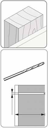
5 2 Mount extension bracket Option A: wood stud walls a b c d e 1/8 1/8 3.2mm 3-1/8 80mm f 2x 10mm M6 x 70mm NOTE: make sure extension bracket is level before tightening bolts. Go to Step 3 on the page 7. 5 of 15


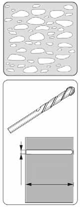
6 2 Mount extension bracket Option B: solid concrete walls a b c d 3/8 WARNING: Mounting holes must be at least 3-1/8 (80mm) deep and must be located within solid concrete, not mortar or covering material. If you drill into an area of concrete that is not solid, reposition mounting holes until both anchors can be fully inserted into solid concrete! 3/ mm 3-1/8 80mm e 2x 2x M6 x 70mm M8 anchor 10mm WARNING: Anchors that are not fully set in solid concrete will not support the applied load resulting in an unstable, unsafe condition which could lead to personal injury and/or property damage. Consult a construction professional if you have any doubt about what this means in regard to your particular situation. NOTE: make sure extension bracket is level before tightening bolts. Go to Step 3 on the page 7. 6 of 15
7 3 Ensure the extension bracket is level. a b c 4 Determine TV/large display mount fasteners NOTE: If a stand is already attached to your TV/large display, remove it according to TV/large display manufacturer directions. Place the display on a clean, fl at, padded surface or, if you prefer, lean the TV/large display against a stable, vertical surface. Several sizes of screws and spacers have been provided for mounting the Glide brackets to your TV/large displaychoose those that best match the depth and diameter of the mounting holes on the back of your TV/large display, along with the design of the area surrounding the mounting holes (Flat, Curved or Inset). TV/Display Style If your TV/large display has a curved or inset mounting hole confi guration, you may need to use the provided spacers or washers with the screws. Hole Depth and Diameter Four sets of display bracket screws have been provided, each of a different diameter: 4mm, 5mm, 6mm, and 8mm. Compare the screws with the diameter of the mounting holes at the back of your TV/large display to fi nd the same size. NOTE: Washer A is provided for use with the 4mm and 5mm screws while Washer B works with 6mm and 8mm screws. Test screw diameters and lengths until you fi nd the right match to your TV/large display. Ø 7 of 15
8 5 Determine if VESA adapters are needed between TV/display and Glide LD Check the shape and size of your TV/large display mounting hole confi guration against the VESA confi gurations shown below. Choose VESA option that matches and continue to Step 6 on the next page. TV/large display Mounting Hole Confi gurations VESA Mounting Hole Confi gurations 100mm Option A 100mm 100 x mm 300mm 200mm Option B 200 x mm 300mm 400mm 300 x x mm Option C 100 x mm Option D 200 x mm 100mm 8 of 15
9 6 Option A: Attach TV/large display to the Glide LD using fasteners determined in step 4 and spacers if needed 6mm 6mm 6mm Continue to Step 7 on page Options B, C, and D Attach VESA Adapters to Glide. Step 6 details continued on the next page. 9 of 15
10 VESA Mounting Hole Confi gurations Option B Option C Option D Rotate VESA plate to access mounting holes. a 8x M4 x 6mm b Step 6 continued on the next page. 10 of 15
11 6 c Options B, C, and D (cont.) Attach TV/large display to the Glide LD using fasteners determined in step 4 and spacers if needed 6mm 6mm 6mm 7 Mount the Glide LD (with attached TV/large display) to extension bracket on wall. 11 of 15
12 Quick-release instructions: to remove the Glide LD from the wall, pull down on the strap below the extension. a b 8 12 of 15
13 9 Test for smooth operation throughout full range of motion. If movements are too easy or diffi cult or if the Glide LD does not stay in desired positions, follow the Adjustment instructions on the following pages to create smooth and easy movements. a Lift b Tilt c Pan (TV/display sideto-side with extension) d Pan (TV/display motion) 13 of 15
14 Adjustment Step Important! You will need to adjust this product after installation is complete. Make sure all your equipment is properly installed on the product before attempting adjustments. This product should move smoothly and easily through the full range of motion and stay where you set it. If movements are too easy or diffi cult or if product does not stay in desired positions, follow the adjustment instructions to create smooth and easy movements. Depending on your product and the adjustment, it may take many turns to notice a difference. Any time equipment is added or removed from this product, resulting in a change in the weight of the mounted load, you should repeat these adjustment steps to ensure safe and optimum operation. a Adjust lift up and down. 10mm Increase Lift Strength If the mounted weight is too heavy or this product does not stay up when raised, then you'll need to increase Lift Strength: Decrease Lift Strength If the mounted weight is too light or this product does not stay down when lowered, then you'll need to decrease Lift Strength: 14 of 15
15 b Adjust tilt To change tilt angle, loosen knob, adjust and tighten knob. For local customer care phone numbers visit: 15 of 15
Neo-Flex Ceiling Mount
 Neo-Flex Ceiling Mount ENGLISH www.ergotron.com User's Guide - English Guía del usuario - Español Manuel de l utilisateur - Français Gebruikersgids - Nederlands Benutzerhandbuch - Deutsch Guida per l utente
User's Guide. StyleView SV43/44 Primary Drawer ENGLISH. For the latest User Installation Guide please visit: 1/16
 User's Guide StyleView SV43/44 Primary Drawer For the latest User Installation Guide please visit: www.ergotron.com User's Guide - English Guía del usuario - Español Manuel de l utilisateur - Français
2x M6 x 25mm. 4x M4 x 15mm
 Monitor Handle Kit ASSEMBLY INSTRUCTIONS Instrucciones de instalación Notice d assemblage Montageanleitungen Installatie instructies Manuali d Istruzione 取扱い説明書安装说明설치안내 www.ergotron.com User's Guide -
Extra Large Full Motion TV Mount for Televisions
 8008981 TV Size Range: 47 ~ 84 Maximum Weight Capacity: 60 kg/132 lbs Maximum Mounting Pattern: 800 mm x 600 mm (31.4 x 23.6 ) Distance to the Wall: 5.5-45 cm Extra Large Full Motion TV Mount for 47-84
Flat Panel Static Wall Mount MSP-SS (GSM-210)
") INSTALLATION INSTRUCTIONS Flat Panel Static Wall Mount (GSM-2) The static wall mount fits most 23 to 30 displays. The mount was designed to adapt to the VESA 75mm/0mm, 0mm/0mm, and 200mm/0mm compliant
INSTALLATION INSTRUCTIONS Flat Panel Static Wall Mount (GSM-2) The static wall mount fits most 23 to 30 displays. The mount was designed to adapt to the VESA 75mm/0mm, 0mm/0mm, and 200mm/0mm compliant
Motorized Ceiling TV Mount
 Motorized Ceiling TV Mount Instruction Manual SKU: MOUNT-E-FD55 Scan the QR code with your mobile device or follow the link for helpful videos and specifications related to this product. https://vivo-us.com/products/mount-e-fd55
Assembly and Setup Manual
 M-12 Series Copyboard / C-12 Series Captureboard Assembly and Setup Manual This is the installation and assembly manual for the M-12 series Copyboard and C-12 series Captureboard. (The copyboard and/or
Assembly and Setup Manual
 M-11 Series Copyboard/C-11 Series Captureboard Assembly and Setup Manual This is the installation and assembly manual for the M-11 series/c-11 series. To the Customer Specialized techniques are required
Remote Control Motorized TV Ceiling Mount
 INSTALLATION MANUAL Remote Control Motorized Ceiling Mount CAUTION: DO NOT EXCEED RATED LISTED WEIGHT. SERIOUS INJURY OR PROPERTY DAMAGE MAY OCCUR! DEHA-400E 15 200x200 300x300 400x200 400x400 55" MAX
Zip12. Charging Desktop Cabinet. User's Guide. Components. Tools Needed ENGLISH. Requires 2 people to remove from box. 6mm. M6 x 35mm Security Screw
 User's Guide Zip12 Charging Desktop Cabinet Requires 2 people to remove from box. Components 1 A B C D E 4x 6.5mm ID 12mm OD 1mm TH Tools Needed 1x 6mm 5-sided Security Wrench 1x M6 x 35mm Security Screw
EVOLVE1-M MONITOR ARM
 EVOLVE1-M MONITOR ARM EVOLVE1-M Rev A 2/17 Model EVOLVE1-M-SLV Model EVOLVE1-M-BLK Model EVOLVE1-M-WHT ASSEMBLY AND ADJUSTMENT EVOLVE1-M MONITOR ARM PARTS AND TOOLS PLEASE REVIEW these instructions before
MBE Mounts and Adapters
 MBE Mounts and Adapters MBE Series en Installation Guide MBE Mounts and Adapters Table of Contents en 3 Table of Contents 1 Important safety instructions 4 2 MBE Series Mounts and Adapters 6 2.1 Unpacking
Quick Installation Guide
 Full Motion Single Monitor Arm, Pole Mount Quick Installation Guide Please Review the entire Quick Installation Guide prior to installation. If you have any questions regarding the compatibility of this
Dual Monitor and Handle Kit
 14"-24.5" (356-622 mm) 14"-24.5" (356-622 mm) Dual Monitor and Handle Kit ASSEMBLY INSTRUCTIONS Instrucciones de instalación Notice d assemblage Montageanleitungen Installatie instructies Manuali d Istruzione
ASSEMBLY AND ADJUSTMENT
 EDGE-WALL MONITOR ARM EDGE-WALL Rev A 2/17 Model EDGE-WALL-SLV ASSEMBLY AND ADJUSTMENT EDGE-WALL MONITOR ARM PLEASE REVIEW these instructions before beginning the installation. Check that all parts and
Quick Installation Guide
 Full Motion Dual Monitor Arm, Pole Mount Quick Installation Guide Please Review the entire Quick Installation Guide prior to installation. If you have any questions regarding the compatibility of this
Charging Cabinet Owner s Manual
 by edugear Charging Cabinet Owner s Manual Before using, please read these operating instructions carefully. They contain important advice concerning the use and safety of your Charging Cabinet. The Charging
StyleView SV41 Cart. with Laptop Mount. User Guide ENGLISH. Tools Needed. Components. 1x 1x
 User Guide StyleView SV4 Cart with Laptop Mount Tools Needed 4mm (9/6") Components A B C 3x 3 4 9x M4 x 8mm x M3.5 x 6mm 5 6 7 8 x x x x M4xmm Features & Specifications... - 4 Set-up...5-3 Adjustment...
Quick Installation Guide
 Full Motion Dual Monitor Arm, Pole Mount Quick Installation Guide Please Review the entire Quick Installation Guide prior to installation. If you have any questions regarding the compatibility of this
StyleView SV43 Cart. with Laptop Mount. User Guide ENGLISH. Tools Needed. Components. 1x 1x
 User Guide StyleView SV43 Cart with Laptop Mount Tools Needed 4mm (9/6") Components A B C 3x 3 4 9x M4 x 8mm x M3.5 x 6mm 5 6 7 8 x x x x M4xmm Features & Specifications... - 4 Set-up...5-3 Adjustment...
Quad Monitor Desk Stand - 13" to 24" Installation Instructions
 Quad Monitor Desk Stand - 13" to 24" Installation Instructions 04-0885A 1 Unpacking Carefully remove the contents and lay out on cardboard or other protective surface Check package contents against the
The Minimalist, Modular, Wall-Mounted Standing Desk
 The StandCrafted Installation Manual Last Update: 03/04/2016 www.standcrafted.com support@standcrafted.com DISCLAIMERS Copyright StandCrafted LLC. All rights reserved. This document is solely intended
Model No. ET-JPF200BE
 Operating Instructions Floor Stand Kit Commercial Use Model No. ET-JPF200BE ET-JPF200WE ENGLISH FRANÇAIS ESPAÑOL DEUTSCH ITALIANO * The above illustration is of this product mounted to an optional projector.
System Storage EXP3000 Rack Installation Instructions
 System Storage EXP3000 Rack Installation Instructions Review the documentation that comes with your rack cabinet for safety and cabling information. When you install the IBM System Storage EXP3000 in a
PFPDARM3 Product Illustration
 PFPDARM3 Product Illustration page 1 of 15 PFPDARM3 Components & Fasteners 1x 1x 4x 4x 8x 4x 1 each TOOLS REQUIRED Phillips Screwdriver 1/2" Wrench 1/2" Socket Wrench 3/32" (2.38mm) 3/16" (4.76mm) 1/8"
Wall-Mounted Sit-Stand Desk - Single Monitor
 Wall-Mounted Sit-Stand Desk - Single Monitor Product ID: WALLSTS1 This wall-mounted sit-stand desk is perfect for areas that don t have enough space for a traditional sitstand desk. Its compact, wall-mounted
StyleView SV43 Cart. with LCD Arm. 12x. 2x 1x. 8x 1x. 1x 1x. 1x 1x. 1x M4 x 8mm. User Guide ENGLISH. Tools Needed. Components
 User Guide StyleView SV43 Cart with LCD Arm Tools Needed 4mm (9/6") Components 3 4 5 4x 8x A M4 x 5mm x M4 x 0mm M4 x 0mm x M3.5 x 6mm 4x x x B 3x 6 4x M4 x 8mm 7 8 9 5mm M4 x 8mm 3mm x M4 x mm Features
PMCL Series Mounts RACK/CEILING/WALL MOUNTS, UNIVERSAL CAMERA MOUNT, MONITORS
 PRODUCT SPECIFICATION control site PMCL Series Mounts RACK/CEILING/WALL MOUNTS, UNIVERSAL CAMERA MOUNT, MONITORS Product Features For Use with VESA -Compliant Monitors Rack Mounts for All 200/300/400 Series
Installation Guide Philips MP20/30/40/50/60/70 IntelliVue M-Series Arm Rail Mount Kit
 Installation Guide Philips MP20/30/40/50/60/70 IntelliVue M-Series Arm Rail Mount Kit The purpose of this guide is to: 1. Describe attachment of Table Top Mount to Mounting Adapter on Arm (page 2). 2.
Digital Menu Board Wall Mount Installation Instructions
 Digital Menu Board Wall Mount Installation MDSWMB2T4249 MDSWMB3T4249 www.microndisplaysolutions.com Table of Contents Important Safety... 3 Models and Specifications... 4 Package Contents... 5 Step 1 Two(2)
StyleView SV43 Cart. with Laptop Mount. User Guide ENGLISH. Tools Needed. Components
 User Guide StyleView SV43 Cart with Laptop Mount Tools Needed 1 2 14mm (9/16") Components 1 2 9x A B C 3x 3 4 M4 x 8mm 2x M3.5 x 6mm 5 6 7 8 2x 2x 2x 2x M4x12mm Features & Specifications... 2-4 Set-up...5-15
Wi-Fi Baby Camera Pan & Tilt Cloud Camera
 Wi-Fi Baby Camera Pan & Tilt Cloud Camera Quick Install Guide DCS-850L Please save this guide for future reference. Read these instructions before using your camera. Do not manually adjust the angle of
MD-BD13B / DUAL SEGMENT TWIN-ARM. For (33-69 cm) LCD desktop computer monitors. User Manual
 LCD desktop computer monitors. User Manual") MD-BD13B / DUAL SEGMENT TWIN-ARM MONITOR mount For 13 27 (33-69 cm) LCD desktop computer monitors User Manual Thank you for choosing Gabor. The Gabor MD-BD13B mounts two 13 27 (33 69 cm) LCD computer monitors
MD-BD13B / DUAL SEGMENT TWIN-ARM MONITOR mount For 13 27 (33-69 cm) LCD desktop computer monitors User Manual Thank you for choosing Gabor. The Gabor MD-BD13B mounts two 13 27 (33 69 cm) LCD computer monitors
Eaton LCD Lift Flat Panel Display System. Installation Guide
 Eaton LCD Lift Flat Panel Display System Eaton LCD Lift Flat Panel Display System Installation Guide Copyright 2011 Eaton Corporation, Worcester, MA, USA. All rights reserved. Information in this document
with External Springs
 Two-Section Broadcast Arm with External Springs Owner s Manual Introduction Thank you for choosing the Auray two-section broadcast arm with external springs. This versatile and sturdy broadcast arm is
MD-BSL15W / SPRING-LOADED TWIN-ARM. For ( cm) LCD desktop computer. User Manual
 LCD desktop computer. User Manual") MD-BSL15W / SPRING-LOADED TWIN-ARM MONITOR mount For 15 27 (38.1 68.6 cm) LCD desktop computer User Manual Thank you for choosing Gabor. The Gabor MD-BSL15W mounts two 15 27 (38.1 68.6 cm) LCD computer
MD-BSL15W / SPRING-LOADED TWIN-ARM MONITOR mount For 15 27 (38.1 68.6 cm) LCD desktop computer User Manual Thank you for choosing Gabor. The Gabor MD-BSL15W mounts two 15 27 (38.1 68.6 cm) LCD computer
UPLIFT 2-Leg Height Adjustable Standing Desk (Version v4 Control Box)
") UPLIFT 2-Leg Height Adjustable Standing Desk (Version v4 Control Box) DIRECTIONS FOR ASSEMBLY AND USE TABLE OF CONTENTS Also watch our assembly video http://bit.ly/2qvkeuf PAGE 1 Safety and Warnings 2
UPLIFT 2-Leg Height Adjustable Standing Desk (Version v4 Control Box) DIRECTIONS FOR ASSEMBLY AND USE TABLE OF CONTENTS Also watch our assembly video http://bit.ly/2qvkeuf PAGE 1 Safety and Warnings 2
Product Overview. Features
 APCF1 Model Tripod Product Overview The Ravelli APCF1 is a Professional Quality Carbon Fiber Tripod providing a solid base for high-end photographic equipment. This model is a mix of carbon fiber and magnesium
Monitor Mount with Articulating Arm and Laptop Riser
 Monitor Mount with Articulating Arm and Laptop Riser ARMUNONB *actual product may vary from photos FR: Guide de l utilisateur - fr.startech.com DE: Bedienungsanleitung - de.startech.com ES: Guía del usuario
Titan Media Cart. Installation and Operation Manual
 Titan Media Cart Installation and Operation Manual Table of Contents INTRODUCTION SERVICE AND SUPPORT... 1 PRODUCT RETURNS... 1 UNPACKING... 1 TITAN SINGLE MEDIA CART... 2 TITAN DUAL MEDIA CART... 2 BEFORE
CHIEF Stand. K3F220/K3G220 (2x2) K3G320 (3x2) EX241UN / -H Multi-Screen Installation Manual
 K3G320 (3x2) EX241UN / -H Multi-Screen Installation Manual") CHIEF Stand K3F220/K3G220 (2x2) K3G320 (3x2) EX241UN / -H Multi-Screen Installation Manual Contents General Information and Cautions. 3 Chapter 1 Removing the Bezel 4 Purpose. 4 How to Remove the Bezel......................5
CHIEF Stand K3F220/K3G220 (2x2) K3G320 (3x2) EX241UN / -H Multi-Screen Installation Manual Contents General Information and Cautions. 3 Chapter 1 Removing the Bezel 4 Purpose. 4 How to Remove the Bezel......................5
Symmetra PX 160. Maintenance Bypass Enclosure. Installation 05/
 Symmetra PX 160 Maintenance Bypass Enclosure Installation 05/2014 www.schneider-electric.com Legal Information The Schneider Electric brand and any registered trademarks of Schneider Electric Industries
Triple-Monitor Arm. Greater comfort and productivity Product ID: ARMTRIO
 Triple-Monitor Arm Product ID: ARMTRIO Create the ultimate ergonomic comfort while freeing up valuable desk space with this triple-monitor arm. You can set up three computer monitors (each up to 24 ) and
Cisco CRS 3-Phase AC Power Distribution Unit Installation Guide 2. Cisco CRS 3-Phase AC Power Distribution Unit 2
 Cisco CRS 3-Phase AC Power Distribution Unit Installation Guide Cisco CRS 3-Phase AC Power Distribution Unit Installation Guide 2 Cisco CRS 3-Phase AC Power Distribution Unit 2 Revised: November 18, 2016,
Rack Installation Guide
 Rack Installation Guide This document provides important information about the Toolless Slide Rail and the Toolless Slide Rail Kit with 1U/2U MA. Each slide rail kit package contains the following items:
2 x Dynamic Arms on 135 Post with C-Clamp
 Installation Guide AWMS-2-D13-C 2 x Dynamic Arms on 135 Post with C-Clamp COMPONENT CHECKLIST RANGE A AWM-LC Post Clamp B AWM-AD Dynamic Arm (x2) C AWM-P13 135 Post D AWM-FC C-Clamp CONTENTS C-Clamp Page
ATV Single Row Disc Harrow OWNER S MANUAL
 ATV Single Row Disc Harrow OWNER S MANUAL WARNING: Read carefully and understand all ASSEMBLY AND OPERATION INSTRUCTIONS before operating. Failure to follow the safety rules and other basic safety precautions
3001 SYSTEM AIR 3005 SYSTEM AIR C/F Fluid Head + Tripod. Operators Manual
 3001 SYSTEM AIR 3005 SYSTEM AIR C/F Fluid Head + Tripod Operators Manual q t o w y a e u s r i d ENGLISH EN Introduction Thank you for purchasing the Miller System AIR. The Miller System AIR is a professional
REMOTE CONTROL MOTORIZED 90 O WALL MOUNT 32-60"
 LEARN MODE instructions as shown below: STEP1: Press and hold f 5 seconds until LED light on the matched remote control stays on, and then press. The buzzer will sound once, the red LED light on the IR
TV & Office Solutions by equip solutions with a high value of benefit
 TV & Office Solutions by equip solutions with a high value of benefit The brand equip stands for a product development driven by quality management and continuous adjustments to the requirements of the
STANDS Speaker Television. All-Steel Speaker Stand SS7725B (page 82)
") STANDS Speaker Television SS8800B+ Power Crank-Up Speaker Stand 80 (page 82) All-Steel Speaker Stand SS7725B 1 2 4 7 1 Cl assic Speaker Stand SS7730B 1 0 6 4 9 Upper Shaft Tubing: 1.375"or 1.5" Upper Shaft
STANDS Speaker Television SS8800B+ Power Crank-Up Speaker Stand 80 (page 82) All-Steel Speaker Stand SS7725B 1 2 4 7 1 Cl assic Speaker Stand SS7730B 1 0 6 4 9 Upper Shaft Tubing: 1.375"or 1.5" Upper Shaft
Wi-Fi Baby Camera Day & Night HD Cloud Camera
 Wi-Fi Baby Camera Day & Night HD Cloud Camera Quick Install Guide DCS-825L Before you Begin Please save this guide for future reference. Read these instructions before using your product. Do not cover
Installation and Assembly: 2 x 2 Video Wall Ceiling Mount for 40" - 55" flat Panel Displays
 Installation and Assembly: 2 x 2 Video Wall Ceiling Mount for 40" - 55" flat Panel Displays Model: DS-VWT955-2X2 EXTENSION COLUMN (SOLD SEPARATELY) COMPATIBILITY Display width must be a minimum of 36"
Owner s Manual Dual Vertical Flat Screen Desk or Clamp Mount
 Owner s Manual Dual Vertical Flat Screen Desk or Clamp Mount MODEL: DDR1527SDC CAUTION: DO NOT EXCEED MAXIMUM LISTED WEIGHT CAPACITY. SERIOUS INJURY OR PROPERTY DAMAGE MAY OCCUR! 75 x 75 100 x 100 27 MAX
Sit-Stand Monitor Arm
 Sit-Stand Monitor Arm Product ID: ARMSTSCP1 This sit-stand monitor arm transforms your desk or tabletop into an ergonomic workstation. The monitor arm features a keyboard tray and easy height adjustment
INSTALLATION INSTRUCTIONS
 INSTALLATION INSTRUCTIONS 19 20 21 01 07 22 23 13 10 12 08 17 18 11 02 14 15 04 03 16 WELCOME PARTS LIST Thank you for purchasing this HealthPoint Technology Cabinet from Humanscale! Before you begin installing
Installation Instructions for AV/VC One Screen Mount Kit
 Installation Instructions for AV/VC One Screen Mount Kit AVS/021/SMK1 REFER ALSO TO MAIN INSTALLATION INSTRUCTIONS FOR AV/VC ONE For dual screen installations you will require 2x AVS/021/SMK1 PARTS INCLUDED:
THE EVO SYSTEM CATALOG
 THE EVO SYSTEM CATALOG THE EVO SYSTEM BUILDING A SYSTEM The evo system starts with a Single Kit, which includes both ends needed to complete the system. Expansion Kits are then added to create the desired
Articulating TV/Monitor Clamp/Grommet Desk Mount Model: DE640S (Hydro Series)
") Articulating TV/Monitor Clamp/Grommet Desk Mount Model: DE640S (Hydro Series) Instruction Manual Images may be different from actual product Disclaimer It is Dyconn s intention to have all the correct
Articulating TV/Monitor Clamp/Grommet Desk Mount Model: DE640S (Hydro Series) Instruction Manual Images may be different from actual product Disclaimer It is Dyconn s intention to have all the correct
UPLIFT 4-Leg Height Adjustable Standing Desk (Version v4.1 Control Box)
") UPLIFT -Leg Height Adjustable Standing Desk (Version v. Control Box) DIRECTIONS FOR ASSEMBLY AND USE TABLE OF CONTENTS PAGE Safety and Warnings 2 2 Usage 2 3 Parts List 3 Assembly Instructions 5 Desk Placement
UPLIFT -Leg Height Adjustable Standing Desk (Version v. Control Box) DIRECTIONS FOR ASSEMBLY AND USE TABLE OF CONTENTS PAGE Safety and Warnings 2 2 Usage 2 3 Parts List 3 Assembly Instructions 5 Desk Placement
TV Brackets by equip The perfect solution to securely mount your TV
 TV Brackets by equip The perfect solution to securely mount your TV No matter what s the size, if you want your TV in a fix position or want it to tilt, we have the solution you re been looking for. intro
DUAL-ARM MONITOR MOUNT For in. ( cm) desktop computer monitors
 desktop computer monitors") LeviTouch DM-502 DUAL-ARM MONITOR MOUNT For 15 27 in. (38.1 68.6 cm) desktop computer monitors User Manual Thank you for choosing Gabor. The Gabor Dual-Arm Desktop Mount can securely support two monitors
LeviTouch DM-502 DUAL-ARM MONITOR MOUNT For 15 27 in. (38.1 68.6 cm) desktop computer monitors User Manual Thank you for choosing Gabor. The Gabor Dual-Arm Desktop Mount can securely support two monitors
C764i Integrated LCD Screen Option. Cardio Theater Integrated Bracket Assembly Instructions
 C764i Integrated LCD Screen Option Cardio Theater Integrated Bracket Assembly Instructions Table of Contents 1 2 3 4 5 6 7 Before You Begin... 3 Obtaining Service... 3 Unpacking the Equipment... 3 Important
INSTALLATION INSTRUCTIONS YAMAHA Speaker Adapter Accessory Model: PAC-Y2
 INSTALLATION INSTRUCTIONS YAMAHA Speaker Adapter Accessory BEFORE YOU BEGIN CAUTION! The instructions provided in this document outline the installation of the PAC-Y2 Lateral Shift Accessory to specific
e550 Wallstation MANUAL
 e550 Wallstation MANUAL 071014 The Enovate Medical e550 Wallstation was designed to set a new standard in quality. Enovate Medical s goal is to provide a wallstation ready for years of use and backed
Treadmill Integrated LCD Screen Option. Cardio Theater Integrated Bracket Assembly Instructions
 Treadmill Integrated LCD Screen Option Cardio Theater Integrated Bracket Assembly Instructions Table of Contents 1 2 3 4 5 6 Before You Begin... 4 Obtaining Service... 4 Unpacking the Equipment... 4 Important
Installation Instruction for MT3430 RAM Mounting Kit
 Installation Instruction for MT3430 RAM Mounting Kit WARNING: Failure to install the mount correctly or modifications to the mount may result in serious injury or damage to property. Contact Psion Teklogix
Blackout Shutter Kits with Breathable Wall Light Traps
 Blackout Shutter Kits with Breathable Wall Light Traps 2018 Growers Supply All Rights Reserved. Reproduction is prohibited without permission. Maintain controlled airflow without sacrificing blackout environments.
INSTALLATION INSTRUCTIONS
 TS1000C TS700C INSTALLATION INSTRUCTIONS CONTENT: 1. Important safety instructions. 2. Specifications and main dimensions. 3. Parts included. 4. Installation. 5. RF remote system. 6. Feature functions
Dual TV/Monitor Desk Mount Stand (Duplex Series) Model: DE9E2S-S
 Model: DE9E2S-S") Dual TV/Monitor Desk Mount Stand (Duplex Series) Model: DE9E2S-S Instruction Manual Images may different from actual product Disclaimer It is Dyconn s intention to have all the correct information represented
Dual TV/Monitor Desk Mount Stand (Duplex Series) Model: DE9E2S-S Instruction Manual Images may different from actual product Disclaimer It is Dyconn s intention to have all the correct information represented
7403 K321. Display Wall Mount. Kit Instructions. Issue A
 7403 K321 Display Wall Mount Kit Instructions Issue A ii Revision Record Issue Date Remarks A Nov 2008 First issue 1 Introduction This kit is used in to secure a 7403 Display Head on a vertical surface.
SPECIFICATION & INSTALLATION GUIDE
 SPECIFICATION & INSTALLATION GUIDE FREEFRAME FP7 v3 Mobile Stand for Flat Panel Display with Motorized Raise and Lower www.gilkon.com.au email: sales@gilkon.com.au phone: (02) 99140900 fax: (02) 99140901
JO-1FD JO-1FD EXPANSION MONITOR STATION
 FK1898 A P0713KD 55061 HANDS-FREE COLOR VIDEO INTERCOM EXPANSION MONITOR STATION POSTE DE SURVEILLANCE D EXTENSION D INTERPHONE VIDÉO COULEUR MAINS LIBRES MONITOR SECUNDARIO DE INTERCOMUNICACIÓN CON VÍDEO
QUIK-LOK S LINE OF WALL-MOUNTING SYSTEMS FOR LCD/PLASMA TV s & PROJECTORS
 QUIK-LOK S LINE OF WALL-MOUNTING SYSTEMS FOR LCD/PLASMA TV s & PROJECTORS Quik-Lok offers a full line of wall mounts for flat-panel LCD/Plasma TV s and monitors, for high standard audio/video integration,
INSTALLATION INSTRUCTIONS
 INSTALLATION INSTRUCTIONS CONTENT: 1. Important safety instructions 2. Specifications and main dimensions 3. Parts included 4. Control box 5. Installation 6. Adjusting the stroke length of the lift 7.
serial number A1159T or lower, which includes all manufactured in 2008 Not compatible and not required. Figure 1 Auger Update Sites Call-Outs R B
 Installation Instructions 1 Auger Carrier Update ADC2350 Air Carts Used with: ADC2350B General Information These instructions explain how to install an Auger Carrier Update on a pre-2009 pull-behind air
UPLIFT 3-Leg Desk Instructions for. Solid Wood Desktops. (Version v4 Control Box) pictured: Solid-wood top with right hand return TABLE OF CONTENTS
 pictured: Solid-wood top with right hand return TABLE OF CONTENTS") UPLIFT 3-Leg Desk Instructions for Solid Wood Desktops (Version v4 Control Box) pictured: Solid-wood top with right hand return TABLE OF CONTENTS PAGE 1 Safety and Warnings 2 2 Usage 2 3 Parts List 3 4
UPLIFT 3-Leg Desk Instructions for Solid Wood Desktops (Version v4 Control Box) pictured: Solid-wood top with right hand return TABLE OF CONTENTS PAGE 1 Safety and Warnings 2 2 Usage 2 3 Parts List 3 4
IBM. Rack Installation Instructions
 IBM Rack Installation Instructions Review the documentation that comes with your rack cabinet for safety and cabling information. When installing your server in a rack cabinet, consider the following:
Rack Installation Instructions
 Rack Installation Instructions Review the documentation that comes with your rack cabinet for safety and cabling information. When installing your server in a rack cabinet, consider the following: v Two
AVT Model Tripod.
 AVT Model Tripod www.ravelliphoto.com Product Overview: The Ravelli AVT professional tripod is a high performance, fluid drag tripod that provides smooth continuous drag control and operates on both pan
FLEXBOX. Installation Guide
 FLEXBOX Installation Guide FLEXBOX 1 Important Safety Instructions WEIGHT LIMIT MAXIMUM WEIGHT 50 LBS. THE STRUCTURE TO WHICH THE BOX IS MOUNTED (CEIL- ING, WALL, TABLE, POLE) MUST BE ABLE TO SUPPORT FIVE
V984Q/C981Q Installation Guide
 V984Q/C981Q Installation Guide [Ver.1.1] Contents: Product Description and Notes Rotation Ventilation Recommendations Carrying Handle Positioning Display Dimensions Front, Top, Right Side, Left Side, Bottom
IQByy with VESA Dock and Power Adapter Cradle
 IQByy with VESA Dock and Power Adapter Cradle Installation Manual 1 Rev: A00 Parts Identification 1 3 1. Monitor Side VESA Dock 2. IQByy thin client with VESA Dock and Power adapter. 3. Stand Side VESA
INSTRUCTION MANUAL. * Design and Specifications are subject to change without notice. ver. 1.0 PRINTED IN KOREA
 INSTRUCTION MANUAL * Design and Specifications are subject to change without notice. ver. 1.0 PRINTED IN KOREA INSTRUCTION MANUAL Thank you for purchasing this product. For proper usage and application,
NAV-1 Lens Support. NAV-2 Lens Support BEFORE YOU BEGIN
 INSTALLATION Lens Support INSTRUCTIONS The Lens Support is compatible with any RPA projector mount. The readily adapts to the following ScreenStar Conversion Lens from Navitar: SSW08 and SST120. LENS SUPPORT
ATLANTIC SHUTTER HARDWARE Storm Rated Installation Instructions
 ATLANTIC SHUTTER HARDWARE Storm Rated Installation Instructions For varying heights of shutters, use the following quantities of hinges per shutter: Height from 12" to 48", Two hinges per shutter Height
GH-50. Gimbal Head. You re on steady ground
 GH-50 Gimbal Head You re on steady ground 1 INTRODUCTION Thank You for choosing Oben! The Oben GH-50 is a gimbal-type tripod head designed to balance a lens along its vertical and horizontal axes. Ideal
Universal Desktop and Monitor Stand
 Universal Desktop and Monitor Stand Installation Instructions Kit P/N: 114-6013 Kit Contents Kit Contents: (1) Stand Assembly (1) VESA Monitor Bracket (1) Bottom Bracket (1) Top Bracket (1) Clamp Bracket
ALL-FLEX ELECTRIC TABLE BASE
 ALL-FLEX ELECTRIC TABLE BASE FLEX2 V3 Rev 01 7 /17 Model FLEX2-SLV-V3 Model FLEX2-BLK-V3 Model FLEX2-WHT-V3 ASSEMBLY AND OPERATION ALL-FLEX ELECTRIC TABLE BASE PARTS AND TOOLS PLEASE REVIEW these instructions
Assembly and mounting Instructions
 PMS-FL Assembly and mounting Instructions Note: Keep your original packaging until assembly is complete. Two persons are required to attach plasma/lcd displays to this mount. If you cannot understand these
Cycles Integrated LCD Screen Option. Cardio Theater Integrated Bracket Assembly Instructions
 Recumbent Upright Cycles Integrated LCD Screen Option Cardio Theater Integrated Bracket Assembly Instructions Table of Contents 1 2 3 4 5 6 7 Before You Begin... 4 Obtaining Service... 4 Unpacking the
Modular Series Mounting Solutions
 At Peerless-AV, we understand that installers and integrators are continuously exposed to unique installation applications. One-size-fits-all mounts simply don t fit all real world applications. Our Modular
V754Q/C751Q Installation Guide
 NEC Display Solutions of America, Inc. V754Q/C751Q Installation Guide [Ver.1.0] Contents: Product Description and Notes Rotation Ventilation Recommendations Carrying Handle Positioning Display Dimensions
PD Way Pan/Tilt Head. You re on steady ground
 PD-117 3-Way Pan/Tilt Head You re on steady ground 1 Introduction Thank You for choosing Oben! This sturdy Oben PD-117 3-Way Pan and Tilt Head offers precise, smooth operation, with independent control
The Nureva Span ideation system. Installation guide. Single panoramic system
 The Nureva Span ideation system Installation guide Single panoramic system Important SAFETY WARNINGS Prior to the installation of this product, the installation instructions should be completely read and
Wall-Mounting your HP TouchSmart. User Guide
 Wall-Mounting your HP TouchSmart User Guide The only warranties for Hewlett-Packard products and services are set forth in the express statements accompanying such products and services. Nothing herein
Control Pad and Touch Unit Installation Guide
 Control Pad and Touch Unit Installation Guide About This Installation Guide This guide describes how to install the Control Pad and Touch Unit (BrightLink Pro 1430Wi) when using the ELPMB28 wall mount
3-Lamp Fluorescent Ring Light 19" INSTRUCTIONS
 3-Lamp Fluorescent Ring Light 19" INSTRUCTIONS Introduction Thank you for choosing Impact. The Impact 3-Lamp Fluorescent Ring Light 19" is a continuous light for photography and video. It casts a soft,
Metham Aviation Design Limited Station Approach, Four Marks, Alton. Hants. GU34 5HN Tel +44 (0) Fax +44 (0)
 Fax +44 (0)") Contents Page General Information 1 Items Supplied 1 Variants 1 Compatibility with other products 2 Mounting the Housing assembly 2 Mounting the Camera/Lens assembly 3 Safety Precautions 4 Control Connections
Contents Page General Information 1 Items Supplied 1 Variants 1 Compatibility with other products 2 Mounting the Housing assembly 2 Mounting the Camera/Lens assembly 3 Safety Precautions 4 Control Connections
V40 Videoboom MAIN OPERATING INSTRUCTIONS INDEX 5. SPECIFICATIONS V40 1. INTRODUCTION 2. LIST OF FUNCTIONS AND PARTS
 MAIN OPERATING INSTRUCTIONS V40 Videoboom INDEX 1. INTRODUCTION 2. LIST OF FUNCTIONS AND PARTS 3. INSTRUCTIONS V40 3.1 ASSEMBLY & SETTING UP 3.2 WEIGHT SYSTEM 3.3 MOUNTING THE VIDEO CAMERA 4. USING THE