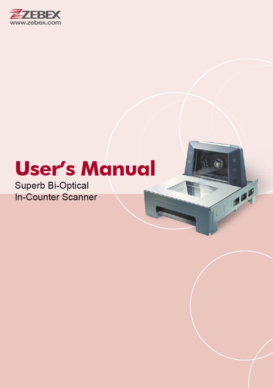
1Z Superb Bi-Optical In-Counter Scanner
|
|
|
- Leonard Shelton
- 5 years ago
- Views:
Transcription
1 1Z
2
3 Revision History Changes to the original manual are listed below: Version Date Description of Version 1.0 July. 01, 2015 Initial release 1.1 December 16, 2015 Corrected dimension in spec 1.2 January 30, 2016 Added top cover installation i
4 Important Notice No warranty of any kind is made in regard to this material, including, but not limited to, implied warranties of merchantability or fitness for a particular purpose. We are not liable for any errors contained herein or incidental or consequential damages in connection with furnishing, performance or use of this material. No part of this document may be reproduced, transmitted, stored in a retrieval system, transcribed, or translated into any language or computer language in any form or by any means electronic, mechanical, magnetic, optical, chemical, manual or otherwise, without express written consent and authorization. We have taken reasonable measures to provide information in this manual that is complete and accurate. However, the material in this guide is for information only; we reserve the right to make changes in product design without reservation and without prior notification. For the latest revision please contact your distributor. All trademarks mentioned herein, registered or otherwise, are the properties of their various respective owners. Copyright All rights reserved. This manual is in A5 format. Please check your printer setting before printing it out. ii
5 Laser Safety The scanner complies with safety standard IEC for a Class I laser product. Avoid long term staring into direct laser light. Radiant Energy: The Advanced Dual-Laser Omnidirectional In-Counter Scanner uses two low-power visible laser diodes operating at 650nm in an opto-mechanical scanner resulting in less than 3.9µW radiated power as observed through a 7mm aperture and averaged over 10 seconds. Do not attempt to remove the protective housing of the scanner, as unscanned laser light with a peak output up to 0.8mW would be accessible inside. Laser Light Viewing: The scan window is the only aperture through which laser light may be observed from this product. A failure of the scanner motor, while the laser diode continues to emit a laser beam, may cause emission levels to exceed those for safe operation. The scanner has safeguards to prevent this occurrence. If, however, a stationary laser beam is emitted, the failing scanner should be disconnected from its power source immediately. Adjustments: Do not attempt any adjustments or alteration of this product. Do not remove the protective housing of the scanner. There are no user-serviceable parts inside. Caution: Use of controls or adjustments or performance of procedures other than those specified herein may result in hazardous laser light exposure. Optical: The use of optical instruments with this product will increase the eye hazard. Optical instruments include binoculars, magnifying glasses, and microscopes but do not include normal eye glasses worn by the user. For CE-Countries This scanner is in conformity with CE standards. Please note that an approved, CE-marked power supply unit should be used in order to maintain CE conformance. iii
6 Table of Contents Important Notice...ii Introduction... 1 Key Features... 1 Unpacking... 2 Components... 3 Connection... 6 Connecting Power... 6 Verifying Scanner Operation... 6 Connecting to the Host... 7 Interface Cable... 7 Interface Cable Replacement... 8 Installation Pre-Installation Considerations Installing the Scanner to the Counter Shelf Mounting Auxiliary Handheld Scanner Connection Connecting EAS System Installing SD Card Installing Top Cover Set Up Configuring the Scanner Power-Up Self-Test Scan Test Parameter Setting Controlling the Scanner from POS System Operation LED Indications Sound Indications Sleep Mode How to Scan Scan Volume Scan Mode Maintaining the Scanner Trouble Shooting Specification Pin Assignment DC JACK Host AUX TDR VFD EAS Interface Cable iv
7 Introduction USER S MANUAL Built with brilliant accuracy and wide scanning angles, Z-6910 bi-optic scanner eliminates traffics in high volume retail environments. Featuring an outstanding one-pass scanning ability, cashiers can scan items without constantly readjusting the scanner positions. By moving the checkout line at a much higher speed, Z-6910 can help you achieve a new elevated level of productivity and efficiency. Key Features First class bi-optical technology Excellent first read rate Visual diagnostic LED Easy on-site configuration and upgradeability 1
 Power supply & power cord (Model")

8 Unpacking The omnidirectional scanner package contains: Interface cable (Type depends on customer selection) Power supply & power cord (Model depends on electrical requirements of your geographic location) If any contents are damaged or missing, please contact your dealer immediately. 2
9 Components Top View Scanner Top View Description Function 1 LED indicator Indicating reading status 2 Control panel 4 buttons controlling scanner functions (see the Font View below) 3 Speaker exit *2 Beep tone indication 4 Top scan window Laser aperture for vertical scanning 5 Bottom Scan window Laser aperture for horizontal scanning 3

10 Rear View USER S MANUAL Scanner Rear View Description Function 6 DC Jack External AC power input 7 Host Port Interface communication connection to the host 8 USB Host Not in use at this time 9 AUX Port Connecting an auxiliary peripheral device, usually a handheld scanner 10 TDR Connecting an optional Top Down Reader 11 Scale Host Not in use at this time 12 VFD Not in use at this time 13 EAS Port Electronic article surveillance connection 4
11 Front View Description Function 14 E commerce Press to read the barcode(s) by mobile commerce reader 15 Self Test Press to start self test 16 Volume Press to control volume 17 Manual EAS deactivation Press to deactivate EAS 5
12 Connection Connecting Power The power supply provides +12 volts DC voltage to the scanner; the detailed power requirement is as below: Voltage AC100~240 Frequency 50~60HZ Current (RMS) 1000mA Output +12V A power cord is required to connect the electrical outlet and power supply. Select the proper IEC power cord for your country. To connect an external power to the scanner, plug the power supply into the power jack on the scanner and then plug the power supply into an AC outlet. Blue LED would light when the scanner is powered and ready to scan. The scanner turns on when the AC power is supplied, and turns off when the power is removed. There is no on/off switch on the scanner itself. Use only an AC/DC power supply approved for the scanner. Use of other power supplies may cause damage to the product, and void the factory warranty. You must verify that the power source will supply clean electrical power to the equipment; that is, it must be free of excess electrical noise. Verifying Scanner Operation Before connecting the scanner to host or mounting to counter, you may follow the procedure below to verify scanning operation. 1. Insert the 10-pin modular plug of the interface cable into the Host connector on the scanner until a firm click is heard. 2. Plug the other end of the cable to the host. 3. Power up the scanner. 4. Present a known-good test barcode to the scanner. The scanner should issue a short beep and the LED should flash red momentarily. 6
13 If the scanner does not produce any beeps, or produces the wrong beeps, or the LED is not lit up, remove the power connection and refer to the section of Troubleshooting. Connecting to the Host The interface cable comes with different host-end connectors, depending on the host. Follow the steps below to connect the device to the host. 1. Turn off the host system. 2. Connect the scanner and the host with the interface cable (Refer to your host manual to locate the correct port for the scanner). 3. Plug the power cable to the jack on the device and connect the power cord to an AC outlet. 4. If necessary, set up the scanner interface with the barcode in the programming guide. (Refer to the Set Up section.) 5. Turn on the host system. Interface Cable The scanner communicates with the host through various types of interfaces. The standard types of interface are: Keyboard wedge RS-232 USB (supporting HID USB, virtual COM USB) IBM 468x/469x 7
14 Interface Cable Replacement The standard interface cable is attached to the scanner with a 10-pin modular connector. When properly seated, the connector is secured in the scanner bottom by a flexible retention tab. You can easily replace the communication cable and set up the interface via programming. Replacement cables can be obtained from your distributor. Follow these steps to replace the interface cable: 1. Turn off the host system and power off the scanner. 2. Disconnect the old interface cable from the host. 3. Press down the small tab on the connector where the old cable is attached to the scanner and pull out the connector. 4. Insert the 10-pin modular plug of a new interface cable into the Host connector on the scanner until it clicks. 5. Plug the new cable into the host. 6. Re-program the scanner interface with barcodes below or refer to the Programming Guide for more setting guidance. Enter/Exit Programming Mode Scan this barcode to enter the set-up or to exit after the set-up is finished. The LED would remain red when in programming mode. 8
15 Return to PC/AT default This barcode allows setting as keyboard wedge interface for IBM PC AT/PS/2 and compatibles. Cover the unwanted barcode to ensure that the scanner read the desired barcode only. Return to RS-232 default The RS-232C interface scanner is often used when connecting to the serial port of a PC or terminal. 9
16 Return to USB default Reading of Return to USB default sets the device into USB interface support. Cover the unwanted barcode to ensure that the scanner read the desired barcode only. Return to Wand Emulation Default 10
17 Installation Pre-Installation Considerations USER S MANUAL Before mounting the scanner, some considerations are as below: Determine the direction of package flow for your application. Locate the optimum scanner position in the counter surface. Pay attention to the product flow, distance to the counter edge and convenience for the operator. Placement of the scanner should allow easy access to other components as well as optimize communication between the scanner, the POS terminal, the additional handheld scanner and any EAS peripheral equipment. Do not route interfaces cables near any electrical motors or other source of electromagnetic interference. To ensure mounting stability, avoid placing the scanner in such a way as to subject it to excess vibration, bumping, spilled liquid, etc. The scanner should be installed in a location away from direct sunlight since high levels of ambient light reduce scanner effectiveness. The scanner housing is designed to provide adequate space for convective cooling. However, to prolong working hours, the scanner should be placed at where there is adequate convective air flow and no major heat producing equipment nearby. The air temperature inside the check stand must not exceed 40 C (104 F). Installing the Scanner to the Counter The scanner is to be mounted in the counter by shelf mounting. You can use a shelf to support the unit. To protect the device, when mounting the scanner, do not turn the scanner upside down or press on the window glass. 11
18 Shelf Mounting You can build a shelf under the counter surface to support the unit. Refer to the following figure for the dimensions of the opening. Shelf Mounting 12
19 Auxiliary Handheld Scanner Connection Auxiliary Port USER S MANUAL The scanner provides an auxiliary port for the use of an additional peripheral device to be connected to the host system via the scanner itself. It is usually used to connect a handheld scanner for items too large to place on the checkstand. The auxiliary port will support 5VDC devices with a 300mA maximum current. If the auxiliary device exceeds this specification, an external power supply will be required to power the auxiliary device. Cable pin-out information for the auxiliary port is as following: Pin Function 1 Reserved (for factory use) 2 N.C. 3 +5V output, 300mA max. 4 RTS 5 Ground 6 TX 7 RX 8 NC 9 CTS 10 Reserved (for factory use) Handheld Data Format Requirements Before installation, the connected handheld scanner must be configured to transmit data format as below. Baud rate 9600 Data bit 8 Parity Stop bit 1 Handshaking Message terminator None RTS/CTS STX/ETX 13
20 Code 39 identifier code ITF 2 of 5 identifier code Chinese post code identifier code UPC-A identifier code UPC-E identifier code EAN-13 identifier code EAN-8 identifier code Codabar identifier code Code 128 identifier code Code 93 identifier code MSI identifier code GS1 CodeBar Omnidirectional identifier code GS1 CodeBar Limited identifier code GS1 CodeBar Expanded Industrial 2 of 5 identifier code Code 11 identifier code Standard 2 of 5 identifier code Matrix 2 of 5 identifier code M I H A E F FF N K L P RS RL RX D O S G Installation of an Auxiliary Scanner Before installation, contact your distributor to make sure the device and firmware version support such a function. Once you re sure about it, follow the steps below to use the auxiliary port as a handheld scanner input port: Follow the following steps to use the auxiliary port as a handheld 1. Configure the handheld scanner data format as above table requirements. 2. Turn off the host system. 3. Connect the handheld scanner to the auxiliary port using the auxiliary cable. 4. Connect the external power supply for the auxiliary scanner (if required). 5. Use the programming barcodes to activate the auxiliary port of the in-counter scanner and set up its data transmission mode. (Refer to its separate Programming Guide.) 14


21 Connecting EAS System The scanner supports the use of an EAS antenna and can work simultaneously with an EAS system using the interlock feature. When enabled, users may scan and deactivate an item at the same time. The scanner s integrated EAS deactivation antenna requires an EAS host cable. 1. Make sure that the power of the EAS system is off. 2. Plug the cable to the appropriate connectors on the scanner and the EAS system. 3. Program the Omnidirectional In-Counter Scanner with the necessary barcodes on the next page. Enter/Exit Programming Mode Scan this barcode to enter the set-up or to exit after the set-up is finished. The LED would remain red when in programming mode. S etting EAS Interlock When enabled, the EAS tag is not de-activated until the associated barcode is decoded. When disabled (default), the EAS tag is de-activated independently of any barcode scanning. 15


 to set the time in millisecond.")
22 Setting EAS Active Use this setting to set the polarity of the EAS allowing the scanner to send an EAS output after a good barcode read to deactivate a tag on the product. S etting EAS Timeout Use this setting to set EAS Timeout. EAS output signal is held in its active state for a good read indication. To set the timeout: 1. Scan the Enter/Exit Programming barcode to begin the setup. 2. Scan 3 ASCII number barcodes (Please see Programming Guide) to set the time in millisecond. For example: 000:disable the feature 001:10 msec 002:20 msec 250:2500 msec (2.5second) 3. Scan the Enter/Exit Programming barcode to save the settings. 16
23 EAS Port Cable pin-out information for the EAS port is as following: RS232 IN ONLY PIN FUNCTION 1 Ground 2 Antenna + 3 Antenna - 4 EAS GPIO OUT 5 EAS GPIO IN 6 Shield 17
24 Installing SD Card Follow the steps below to insert the SD card. 1. Carefully lift the window glass and take it off the scanner. 2. Open the SD card slot cover. 3. Insert the SD card. Please power off the device before proceeding. 18


25 Installing Top Cover Follow the steps to install top cover. 1. To close the cover, align the two bottom latches on the cover to their corresponding bolts on the scanner as shown below. 2. Push down the cover into a secure position. Please make sure you attach all four latches to the bolts and there is no gap in between the cover and the scanner. 19
26 Set Up Configuring the Scanner The scanner is either pre-programmed to suit the situation, or it automatically detects and is ready to go. In certain cases no setup is required. In other cases the scanner must be informed about what kind of system it is connected to. This can be done in a few moments using the programming barcodes in the separate Programming Guide. The programming section may be used to set a number of parameters on the scanner: communication interface type, sleep mode timing, same-code delay time, barcode symbologies, and more advanced settings like setting headers and trailers. The settings are to be stored in non-volatile memory and are preserved even when the scanner is powered down. Individual parameters may be set at any time without affecting the other parameters. Power-Up Self-Test The scanner would automatically run the self-test when the power is supplied. It is to verify that the scanner and interface are functioning properly and takes only seconds. The unit would give four beeps in series to indicate that the scanner passed self-test; blue LED would light on afterwards. It the scanner fails the self-test, both the blue and red LED would light on (appearing the color purple); a continuous beeping may also be heard. Scan Test After the scanner passes the power-up self-test, it is ready to scan. Follow the steps below to ensure that your scanner can work well with your host system. With the scanner running (blue LED lights up) and the host system on, try to scan several known-good barcodes. Check the results on the POS screen. If the scanner is reading okay, it is likely that no further setup is necessary. If the POS screen does not show the expected scans, go to the Parameter Setting section below. 20
27 Parameter Setting When the scanner is powered on (blue LED lights up), find the <Enter/Exit Programming Mode> barcode in the Programming Guide and present this barcode to the scanner. When the scanner gives two beeps (one high and one low) and the LED turns red, it means the scanner is in programming mode. Decide which parameters are required and find their barcodes in the Programming Guide. Cover unwanted codes with your hand and present the desired codes one by one to the scanner; the scanner beeps once as it accepts each code. For some parameter setting, such as barcode length and identifier code, it is required to scan the Set barcode to save the configuration. When done, again present the <Enter/Exit Programming Mode> barcode. The scanner beeps twice of the same tone, and the LED returns to blue. It means the scanner has been programmed. Test again with known-good barcodes. If results are good, you are done setting up. Otherwise, return to step 1 and try again. Read Enter/Exit programming mode barcode to start configuration Change scanner setting by scanning the barcodes of the desired function Select code 39 full ASCII table? Yes No Read Enter/Exit programming mode barcode to save and exit Read Save setting to confirm barcode to end the configuration 21
28 Controlling the Scanner from POS System The scanner can be controlled from the POS system via the RS-232C interface. Controlling can be accomplished by transmitting the following single byte commands to the scanner. The default settings of the commands are as follows: ASCII Code Function Byte is Also Called: 0E Hex enable (resumes disable) Shift Out or <Ctrl-N> 0F Hex disable Shift In or <Ctrl-O> 12 Hex sleep DC2 <Ctrl-R> 14 Hex wake up (resumes sleep) DC4 <Ctrl-T> When the scanner is disabled (unable to scan), the motor of the scanner will stay on until the scanner goes into sleep mode. 22
29 Operation LED Indications There are red and blue dual color LED indications on the top of the device indicating the operational status of the scanner. LED Status LED off Steady blue light One red flash Steady red light Flashing blue light Steady blue light Flashing red light Dot Matrix E3 Dot Matrix E2 Indication No power supplied to the scanner. The scanner is powered on and ready to scan. A barcode has been successfully decoded. A barcode has been successfully decoded, but the object is not removed from the scan window. The scanner is in programming mode. The scanner is in sleep mode. This indicates the scanner has a motor or laser failure. For motor failure, a periodic beep is sounded. In this case, return the unit for repair. The scanner is programmed in USB interface but not connected to a host device. Laser Motor Sound Indications The device uses a speaker to give audio feedback on scanner operation. The beeper tone and duration are adjustable with the Programming Guide. Beeps One beep Two beeps: high-low Two beeps: same tone Four beeps in series 23 Indication A barcode has been successfully decoded. The scanner has entered programming mode. Scanner has returned from programming to normal mode. This indicates the scanner passed self-test when powered on and is operating properly.
30 Sleep Mode After the scanner has been inactive for a specific length of time, the laser and the motor would automatically turn off. This state is called sleep mode. The blue LED would blink as indication. It takes two steps to enter the sleep mode. The first step is the laser switching off after 10 minutes; the second step is the motor switching off after 30 minutes. The time period is programmable. The scanner has two IR sensors that detect activity in front of the scan window. To wake up the scanner, simply present an object into the IR detection range in front of the scan window. The detecting distance is about 15cm (5.9 inch) from the scan window while in condition with effectiveness of environment lights. The detecting distance is also programmable. 24
 in front of the scan window. Barcodes are most effortlessly scanned when swept through the scan volume from the scan window.")
31 How to Scan Scan Volume USER S MANUAL The device is an omnidirectional presentation scanner with a 10-direction scan field with a 40-line scan pattern. The scan volume extends approximately 20cm (8 ) in front of the scan window. Barcodes are most effortlessly scanned when swept through the scan volume from the scan window. On the other hand, the two LED indicate reading status as well as package flow. As illustrated in Figure 13, the product flow can be from the right to the left or the left to the right. Scan Mode The scanner is to be mounted in a check stand. It works in three scanning modes to cater to different counter placement and operation convenience: Sliding mode: Users slide items over the counter surface without grasping or picking them up. Sweeping mode: Users sweep items through the scan volume. Left to right or right to left are both okay. Presentation mode: Users present items to the scan window. The scanner can read barcodes as long as the item is within the scan volume, with or without the barcode facing the scan window. Facing barcode labels in the direction of scanning or toward the scan window will optimize the scan rate. 25
32 Maintaining the Scanner The scanner is designed for long-term trouble-free operation and rarely requires any maintenance. Only an occasional cleaning of the scanner window is necessary in order to remove dirt and fingerprints. It can be cleaned while the scanner is running. When cleaning, wipe the scan window with a soft lint-free cloth and a non-abrasive cleaner to avoid scratching and damaging the scan window. Do not spray water or cleaning liquid directly into the window. If the scanner s housing needs cleaning, use a mild cleaning agent that does not contain strong oxidizing chemicals; otherwise the exterior may be damaged. 26
33 Trouble Shooting USER S MANUAL This section contains information about how to solve problems that you may encounter when operating the scanner. However, before referring to the tips, make sure that the scanner is installed as instructed in this manual and that all cables are properly connected. If the problem remains, please contact your dealer. Problem The scanner is on but cannot read barcodes. The scanner is on, but the motor is not rotating. A barcode cannot be read. The scanner does not accept more than two or three barcode labels. A barcode is read by the scanner but not accepted by the POS system. Diagnostic Tips The scanner window is dirty. Clean the scanner window as described in the Maintenance section. The presented barcode type is not enabled. Select the barcode type in the Programming Guide. The host disables the scanner. The barcode type you presented to the scanner is not supported. The scanner has entered the sleep mode. Press the switch on the top of the scanner to wake up the scanner (or use the wake protocol.) There is no proper handshaking with the POS system. Switch on the POS system and check the connection and communication settings. The scanner is continuously seeing a barcode. Remove all barcode labels out of the scan volume of the scanner and try again. The scanner cannot send the data to the POS system. There is no proper handshaking between the scanner and the host. Make sure that all cables are connected and your POS system is ready to receive data. The interface cable is not connected to the correct port of your POS system. Refer to the manual of your POS system to locate the serial port. The communication settings of the system and scanner do not match. Adjust the settings in order to be equal for both devices. The interface cable does not suit your POS system. Contact your dealer for the correct interface cable. The software running on the POS system does not support the data format of the barcode label. 27
34 Specification OPERATIONAL Light Source 2 dual 650 nm visible laser diodes (VLD) Depth of Field Horizontal: cm (13mil) Vertical: 0-250cm (13mil) Scan Line Horizontal 40 lines & vertical 40 lines Horizontal 80 & vertical 80 scans per second (single-line); Scan Rate Horizontal 3,200 & vertical 3,200 scans per second (omnidirectional) Minimum Bar Width Horizontal: 5 mil Vertical: 6mil Scan Pattern Horizontal 5 & vertical 5 directions Indicator Two-color LED (blue & red); 2 LED DOT matrix (5 7) Beeper Operation Programmable tone & beep time RS-232, USB HID, USB Virtual COM, IBM468X, keyboard, OPOS System Interface USB; Auxiliary powered RS-232 port; EAS port; SD slot Remote Display: VFD 20*2 Characters (optional) PHYSICAL Dimension [142.1 (above counter) (below counter)] mm POWER Power Supply Voltage 100~240VAC 50/60Hz DC Input Scanner +12V, REGULATORY EMC CE EN55022,B, FCC part 15 Class A,VCCI,BSMI Laser Class IEC Class 1 ENVIRONMENTAL Operating Temperature 0 C 40 C (32 F 104 F) Storage Temperature -20 C~60 C(-4 F 140 F) Humidity 5% 85% RH (non-condensing) Light Level Max Lux Compatibility EAS compatible DECODING CAPABILITY UPC/EAN/JAN, UPC-A & UPC-E, EAN-8 & EAN-13, JAN-8 & 1D Barcode JAN-13, ISBN/ISSN, Code 39, Codabar, Code 128 & EAN 128, Code 93, ITF 2 of 5, MSI, China Postal Code, Code 32 (Italian Pharmacode) 28
35 Pin Assignment DC JACK USER S MANUAL INNER +12V OUTER GND Host PIN Keyboard Wedge RS232 USB 1 N/C RTS (RS232 level) N/C 2 Keyboard_ Data N/C USB_D+ 3 PC_ Clock N/C USB_D- 4 Ground Ground Ground 5 N/C CTS (RS232 level) N/C 6 N/C RXD (RS232 level) N/C 7 Keyboard_ Clock N/C N/C 8 PC 5V N/C USB 5V 9 PC_ Data N/C N/C 10 N/C TXD (RS232 level) N/C AUX RS232 IN ONLY PIN FUNCTION 1 Reserved (for factory use) 2 N.C. 3 +5V output, 300mA max. 4 RTS 5 Ground 6 TX 7 RX 8 NC 9 CTS 10 Reserved (for factory use) 29
36 TDR USER S MANUAL UART IN ONLY PIN FUNCTION 1 +5V 2 TXD 3 RTS 4 GOOD READ 5 GND 6 CTS 7 RXD 8 TRIGGER VFD RS232 IN ONLY PIN FUNCTION 1 Reserved (for factory use) 2 +5V 3 NC 4 RTS 5 Ground 6 TX 7 RX 8 NC 9 CTS 10 Reserved (for factory use) EAS RS232 IN ONLY PIN FUNCTION 1 Ground 2 Antenna + 3 Antenna - 4 EAS GPIO OUT 5 EAS GPIO IN 6 Shield 30
37 Interface Cable Keyboard Wedge Cable (for PS/2) RS-232C Cable DTE Pin Out RS-232C Cable DCE Pin Out USB HID / Virtual COM / OPOS Cable 31 PIN-OUT CONFIGURATION P1- MINI DIN P2- MINI DIN (F) (M) Din Din Din Din 1. PC Data 1. KB Data 2. N.C. 2. N.C. 3. GND 3. GND 4. PC 5V 4. PC 5V 5. PC Clock 5. KB Clock 6. N.C. 6. N.C. DB-9 (F) FUNCTIO N 2 TX 3 RX 7 CTS 8 RTS 5 GND DB-9 (F) FUNCTIO N 2 RX 3 TX 7 RTS 8 CTS 5 GND Connector USB Type A Functio n 1. VCC 2. D- 3. D+ 4. VSS
2D Image Handheld Scanner
 1 Revision History Changes to the original manual are listed below: Version Date Description of Version 1.0 9/6/2018 Initial release i Important Notice No warranty of any kind is made in regard to this
2D Image Hands-Free Scanner
 8072 1 Revision History Changes to the original manual are listed below: Version Date Description of Version 1.0 03/24/2016 Initial release i Important Notice No warranty of any kind is made in regard
LS-1000 Series Laser Barcode Scanner User s Manual Rev. A0
 LS-1000 Series Laser Barcode Scanner User s Manual Rev. A0 FCC Notes: This equipment generates, uses, and can radiate radio frequency energy and, if not installed and used in accordance with the instructions
Projection Laser Scanner SERIES 2600
 ISO 9002 Certified Lead with technology Win customers with service Projection Laser Scanner SERIES 2600 OPERATION MANUAL OPERATION MANUAL Laser Safety The 2600 laser scanner complies with safety standard
SM2420. Manual del Usuario ESPECIFICACIONES SUJETAS A CAMBIO SIN PREVIO AVISO.
 SM2420 Manual del Usuario ESPECIFICACIONES SUJETAS A CAMBIO SIN PREVIO AVISO. Importance This equipment generates, uses and can radiate radio frequency energy. If not installed and used in accordance with
Z-6910M Superb Bi-Optical In-Counter Scanner
 Z-6910M Superb Bi-Optical In-Counter Scanner Standard Device DC Jack INNER +12V OUTER GND Host Port Pin Keyboard Wedge RS-232C USB 1 N/C RTS (RS232 level) N/C 2 Keyboard_ Data N/C USB_D+ 3 PC_ Clock N/C
Installation & User s Manual Scantech-ID LIBRA L-7050 Multi-purpose Omni-directional scanner
 Installation & User s Manual Scantech-ID LIBRA L-7050 Multi-purpose Omni-directional scanner Copyright 2010, Scantech-ID BV. This manual is copyrighted, with all rights reserved. Under the copyright laws,
Innovation By Design
 Innovation By Design LAZERLOGIC LL2424 Programme Manual 01256 840927 @ sales@lazerlogic.com Kensington House, 21 Mill Road, Basingstoke, Hampshire RG24 9SN Enter/Exit Programming Mode ( represents the
Fixed mount CCD bar code reader NFT Specification Ver. 1.0
 Fixed mount CCD bar code reader NFT-2100 Specification Ver. 1.0 Version Control number : Model : SS05011 NFT-2100 Version Date Revisions Description Ver 1.0 2005/06/09 - First registration 1. About this
2DScan TM Barcode Scanner
 2DScan TM Barcode Scanner Quick Start Manual Default Check Version FCC WARNING STATEMENT This equipment has been tested and found to comply with the limits for a Class B digital device, pursuant to Part
Leuze electronic. Dimensioned drawing. Electrical connection. Accessories
 2D-code hand-held scanner Dimensioned drawing 4-14 V DC We reserve the right to make changes BP_IT4600_4800_GB.fm Part No. 501 06667! Hand-held scanner for Data-Matrix Codes and Bar Codes! Large reading
MS810 Laser Scanner. Product Reference Guide. Rev. A
 MS810 Laser Scanner Product Reference Guide Rev. A 1 Preface About This Manual This manual explains how to install, operate and maintain the Unitech MS810 Laser Scanner. No part of this publication may
MS810 Laser Scanner. Product Reference Guide. Rev. A
 MS810 Laser Scanner Product Reference Guide Rev. A 1 Preface About This Manual This manual explains how to install, operate and maintain the Unitech MS810 Laser Scanner. No part of this publication may
Nuscan 3200 Optical Laser Barcode Scanner
 Nuscan 3200 Optical Laser Barcode Scanner Programming Manual FCC Compliance This equipment has been tested and found to comply with the limits for a Class A digital device, pursuant to Part 15 of the FCC
Laser Barcode Scanner Model no. LS6007 FS5027
 Laser Barcode Scanner Model no. LS6007 FS5027 User s Manual FCC Compliance This equipment has been tested and found to comply with the limits for a Class A digital device, pursuant to Part 15 of the FCC
2D Imaging Barcode Scanner GLLS. Programming Guide. Advanced Handheld High-Speed Laser Scanner
 2D Imaging Barcode Scanner GLLS Programming Guide 1 Advanced Handheld High-Speed Laser Scanner Revision History Changes to the original manual are listed below: Version Date Description of Version 1.0
Installation & User s Manual. Scantech ID MICA M-9030 Laser Barcode Scanner
 Installation & User s Manual Scantech ID MICA M-9030 Laser Barcode Scanner Installation & User s Manual Scantech-ID MICA M-9030 Copyright 2009, Scantech-ID BV. This manual is copyrighted, with all rights
Wireless Laser Barcode Scanner ils 6300BU. User s Manual
 Wireless Laser Barcode Scanner ils 6300BU User s Manual FCC Compliance This equipment has been tested and found to comply with the limits for a Class A digital device, pursuant to Part 15 of the FCC Rules.
LS8000 USER MANUAL. Kitchen Display Station Controller. with Android TM
 LS8000 Kitchen Display Station Controller with Android TM USER MANUAL NOTICE The manufacturer of the kitchen video controller makes no representations or warranties, either expressed or implied, by or
MS5100. Eclipse Series. User s Guide
 MS5100 Eclipse Series User s Guide Disclaimer Honeywell International Inc. ( HII ) reserves the right to make changes in specifications and other information contained in this document without prior notice,
Portable Data Collector Series Z-9000 ( Version 1.0) User s Manual ZEBEX INDUSTRIES INC.
 User s Manual ZEBEX INDUSTRIES INC.") Portable Data Collector Series Z-9000 ( Version 1.0) User s Manual ZEBEX INDUSTRIES INC. WWW.ZEBEX.COM Revision History Changes to the original manual are listed below: Version Date Description of Version
Portable Data Collector Series Z-9000 ( Version 1.0) User s Manual ZEBEX INDUSTRIES INC. WWW.ZEBEX.COM Revision History Changes to the original manual are listed below: Version Date Description of Version
Users Manual OPN Pocket Memory Scanner
 Users Manual OPN 2001 Pocket Memory Scanner CAUTION: This user s manual may be revised or withdrawn at any time without prior notice. Copyright 2006 Opticon Sensors Europe B.V. All rights reserved. This
READER MAH 100 TECHNICAL MANUAL READER MAH 100
 READER MAH 100 TECHNICAL MANUAL Designation of this documentation: Technical manual for the Reader MAH 100 Version of the described product: 1.0 Editorial version of this documentation: 09/02 Copyright
2D Imaging Barcode Scanner GLLS. Programming Guide. Advanced Handheld High-Speed Laser Scanner
 2D Imaging Barcode Scanner GLLS Programming Guide 1 Advanced Handheld High-Speed Laser Scanner Revision History Changes to the original manual are listed below: Version Date Description of Version 1.0
Omni-Directional 1D Barcode Scanner user manual
 Omni-Directional 1D Barcode Scanner user manual Model 177597 MAN-177597-UM-1110-02 Installation & User s Manual Copyright 2009. This manual is copyrighted, with all rights reserved. Under the copyright
icore Kiosk system Installation Guide
 icore Kiosk system Installation Guide The reproduction, transmission or use of this document or its contents is not permitted without express authority. Offenders will be liable for damages. All rights,
7820 Solaris. Bar Code Scanner. User s Guide
 7820 Solaris Bar Code Scanner User s Guide Disclaimer Honeywell International Inc. ( HII ) reserves the right to make changes in specifications and other information contained in this document without
Specification or version may be subject to change without notice. The actual specification and version are based on the product delivered.
 1 IMPORTANT NOTICE No warranty of any kind is made in regard to this material, including, but not limited to, implied warranties of merchantability or fitness for any particular purpose. We are not liable
Nearus USB2.0 Camera Manual NU-350-USB2PTZ-B
 Nearus USB2.0 Camera Manual NU-350-USB2PTZ-B Safety Tips Please read this manual carefully before installing the camera. Keep the camera away from violent vibration, physical stress, moisture, extreme
burst laser
 burst laser USERS MANUAL www.venuelightingeffects.com Introduction Congratulations on your purchase of Venue s Burst Laser. Designed to operate as a simple stand-alone unit or external addition to your
RT209 OEM Scan Engine. RT209 Integration Guide. Integration Guide
 RT209 OEM Scan Engine Integration Guide Table of Contents Chapter 1 Introduction... 1 Overview... 1 Aimer... 1 Illumination... 1 Chapter 2 Installation... 2 General Requirements... 2 ESD... 2 Dust and
Manual de Programación
 Manual de Programación SM2410, SM2410B, SM2420 y SM2430 ESPECIFICACIONES SUJETAS A CAMBIO SIN PREVIO AVISO. Enter/Exit Programming Mode (This barcode is also found at page 8.) IMPORTANT NOTICE Every effort
COPYRIGHT 2009,SCSC. Manual P/No: SCCM - 80S-01A Released Date: Oct 31, 2009
 To begin the configuration procedures Thank you for purchasing the scanner. Inside each packaging box, you may find the scanner, the interface cable and user's fuide. Configuration manual might be optional
Laser Barcode Scanner ARP Nr User s Manual
 Laser Barcode Scanner ARP Nr. 853782 User s Manual FCC Compliance This equipment has been tested and found to comply with the limits for a Class B digital device, pursuant to Part 15 of the FCC Rules.
BluScan TM Barcode Scanner
 BluScan TM Barcode Scanner Quick Start Manual Default Check Version FCC WARNING STATEMENT This equipment has been tested and found to comply with the limits for a Class B digital device, pursuant to Part
PD1100 STAND-ALONE PROGRAMMING & USER S GUIDE. use the freedom
 PD1100 STAND-ALONE ALPHANUMERIC POLE DISPLAY PROGRAMMING & USER S GUIDE use the freedom Forward The information contained in this user s guide is subject to change without notice. This Programming and
KB9000 Programmable Touch Bumpbar USER MANUAL
 KB9000 Programmable Touch Bumpbar USER MANUAL Table of Contents 1 Introduction...2 1.1 Safety Information... 2 1.2 Electromagnetic compatibility statement... 3 2 Overview... 4 2.1 Appearance... 4 2.2 Features...
MT80 2D Mini Imager+MD200 Decoder Baord, Integration Guide, V0.5 MT80 (2D. Mini Imager) MD200 (Decoder. Board) Integration Guide
 MD200 (Decoder. Board) Integration Guide") MT80 (2D Mini Imager) MD200 (Decoder Board) Integration Guide Version 0.5 DATE: 2018/07/04 TABLE OF CONTENTS 1. INTRODUCTION...1 1-1. Block Diagram...1 1-2. Electric Interface...2 1-2-1. Pin Assignment...
MT80 (2D Mini Imager) MD200 (Decoder Board) Integration Guide Version 0.5 DATE: 2018/07/04 TABLE OF CONTENTS 1. INTRODUCTION...1 1-1. Block Diagram...1 1-2. Electric Interface...2 1-2-1. Pin Assignment...
IT 1910i. Industrial 2D-code hand-held scanner TECHNICAL DESCRIPTION. make technical changes EN /06. We reserve the right to
 IT 1910i Industrial 2D-code hand-held scanner EN 50123791 2013/06 We reserve the right to make technical changes TECHNICAL DESCRIPTION 2013 Leuze electronic GmbH + Co. KG In der Braike 1 D-73277 Owen /
Models: TD3000 Series. Table Displays. 2 by 20 character display USER MANUAL
 Models: TD3000 Series Table Displays 2 by 20 character display USER MANUAL i NOTICE The manufacturer of the POS table display makes no representations or warranties, either expressed or implied, by or
AD-8923-BCD. Remote Controller (BCD) INSTRUCTION MANUAL 1WMPD
 INSTRUCTION MANUAL 1WMPD") AD-8923-BCD Remote Controller (BCD) INSTRUCTION MANUAL 1WMPD4002137 2010 A&D Company, Limited. All rights reserved. No part of this publication may be reproduced, transmitted, transcribed, or translated
AD-8923-BCD Remote Controller (BCD) INSTRUCTION MANUAL 1WMPD4002137 2010 A&D Company, Limited. All rights reserved. No part of this publication may be reproduced, transmitted, transcribed, or translated
IMAGETEAM 4200 Hand Held Linear Imager. Quick Start Guide
 IMAGETEAM 4200 Hand Held Linear Imager Quick Start Guide Disclaimer Hand Held Products, Inc. ( Hand Held Products ) reserves the right to make changes in specifications and other information contained
MT80 2D Mini Scan Engine, Integration Guide, V0.3 MT80 (2D. Mini Scan Engine) Integration Guide. Version 0.3 DATE: 2018/03/14
 Integration Guide. Version 0.3 DATE: 2018/03/14") MT80 (2D Mini Scan Engine) Integration Guide Version 0.3 DATE: 2018/03/14 TABLE OF CONTENTS 1. INTRODUCTION...1 1-1. MT80 Block Diagram... 1 1-2. Electric Interface... 2 1-2-1. Pin Assignment...2 1-2-2.
MT80 (2D Mini Scan Engine) Integration Guide Version 0.3 DATE: 2018/03/14 TABLE OF CONTENTS 1. INTRODUCTION...1 1-1. MT80 Block Diagram... 1 1-2. Electric Interface... 2 1-2-1. Pin Assignment...2 1-2-2.
RS-232/422/485 to Copper or Fiber. Ethernet Converter. User s Manual
 RS-232/422/485 to Copper or Fiber Ethernet Converter User s Manual Table Of Contents TABLE OF CONTENTS... 1 INTRODUCTION... 3 PRODUCT OVERVIEW... 3 PRODUCT FEATURES... 3 PACKING LIST... 4 LED INDICATORS...
PrintPAD MC65. User Guide
 110288-000 PrintPAD MC65 User Guide TABLE OF CONTENTS PrintPAD MC65 Printer Views...1 Open View...1 Closed View...1 Using Batteries: General Guidelines...1 Installing and/or Replacing Batteries...2 Charging
IDENTIFICATION DS4800 APPLICATIONS ADVANTAGES
 Enhanced Connectivity Ease of use Configuration SW Tool ACR4 technology Smart focus adjustment IDENTIFICATION APPLICATIONS Automated warehousing Reading on pallets Picking systems Automated shop floor
4170 POS System Installation Guide
 4170 POS System 4170 Installation Guide Thank you for selecting UTC RETAIL s innovative Model 4170 Point of Sale solution! This Installation Guide will help you efficiently install the 4170 POS. The document
-C5RS-LC RS232 EXTENDER
 XTENDEX Series ST-C5RS-LC RS232 EXTENDER Installation and Operation Manual ST-C5RS-LC RS232 Extender Man249 Rev. 10/30/17 TRADEMARK XTENDEX is a registered trademark of Network Technologies Inc in the
IR Varifocal IP66 Weatherproof Cameras
 IR Varifocal IP66 Weatherproof Cameras Products: CFC6067VF, CFC6067VF2 Please read this manual before using your camera, and always follow the instructions for safety and proper use. Save this manual for
MS336 2D Imager Scanner
 MS336 2D Imager Scanner Product Reference Guide Rev. C Preface About This Manual This manual explains how to install, operate and maintain the Unitech MS336 Imager Scanner. No part of this publication
FengMi Wemax One Laser Projection TV
 FengMi Wemax One Laser Projection TV User`s Manual About electrical ground Transportation Use this device only with a compulsory grounding condition. It is recommended that you use the original packaging
2190 POS System User Guide
 2190 POS System 2190 User Guide Thank you for selecting UTC RETAIL s innovative Model 2190 Point of Sale solution! This guide is designed to acquaint you with the features and functionality of the 2190
PD-2300 Series USER S MANUAL. VFD CUSTOMER DISPLAY for ALPHANUMERICAL DISPLAY in 2 x 20 format. Rev. : Original
 2100 2200 PD-2300 Series USER S MANUAL VFD CUSTOMER DISPLAY for ALPHANUMERICAL DISPLAY in 2 x 20 format Rev. : Original FCC NOTICE SOME IMPORTANT NOTES This equipment generates, uses, and can radiate radio
2100 POS System User Guide
 2100 POS System 2100 User Guide Thank you for selecting UTC RETAIL s innovative Model 2100 Point of Sale solution! This guide is designed to acquaint you with the features and functionality of the 2100
Toll Free: Tel: Fax:
 Toll Free: 1-888-865-6888 Tel: 510-226-8368 Fax: 510-226-8968 Email: sales@rackmountmart.com User Manual LCDK 1070 DVI-D KVM Legal Information First English printing, October 2002 Information in this document
MODEL PORTI-T. (Kiosk&Ticket Printer) Rev. 2.0
 Rev. 2.0") MODEL PORTI-T (Kiosk&Ticket Printer) Rev. 2.0 WOOSIM SYSTEMS Inc. #501, Daerung Technotown 3th, 448, Gasan-Dong, GeumChun-Ku, Seoul, Korea Tel : +82-2-2107-3700 Fax : +82-2-2107-3707 URL: http://www.woosim.com
MODEL PORTI-T (Kiosk&Ticket Printer) Rev. 2.0 WOOSIM SYSTEMS Inc. #501, Daerung Technotown 3th, 448, Gasan-Dong, GeumChun-Ku, Seoul, Korea Tel : +82-2-2107-3700 Fax : +82-2-2107-3707 URL: http://www.woosim.com
DVI KVM Switch user manual Model
 DVI KVM Switch user manual Model 156066 INT-156066-UM-0808-01 introduction Thank you for purchasing the INTELLINET NETWORK SOLUTIONS DVI KVM Switch, Model 156066. This convenient device lets you control
IG380 Imager Bar Code Scanner SPECIFICATION. Model No. : IG380 Imager Bar Code Scanner. Spec. Version & Revision Date: V
 SPECIFICATION Customer : Customer s Model No. : Model No. : IG380 Imager Bar Code Scanner Date : Sample Serial No. : Spec. ersion & Revision Date: 2018.09.25 Received/Approved by 1 Revision History ersion
F1000 User's Manual. (Version: V1.01)
") (Version: V1.01) Contents Chapter 1 Overview... 2 Chapter 2 Installation... 3 2.1 Installation guide... 3 2.1.1 Installation position... 3 2.1.2 NEMA4 standard installation... 3 2.1.3 Environment precautions...
(Version: V1.01) Contents Chapter 1 Overview... 2 Chapter 2 Installation... 3 2.1 Installation guide... 3 2.1.1 Installation position... 3 2.1.2 NEMA4 standard installation... 3 2.1.3 Environment precautions...
SlimScan BT Full Manual
 SlimScan BT Full Manual ASP Microcomputers 456 North Road, Ormond, Victoria, 3204 Australia Telephone: (03) 9578-7600 FAX: (03) 9578-7727 email: solutions@asp.com.au World Wide Web: http://www.asp.com.au
METROLOGIC INSTRUMENTS, INC. MS2220 StratosS Scanner / Avery Scale Installation and User s Guide
 METROLOGIC INSTRUMENTS, INC. MS2220 StratosS Scanner / Avery Scale Installation and User s Guide Copyright 2006 by Metrologic Instruments, Inc. All rights reserved. No part of this work may be reproduced,
QuantumT Omnidirectional Laser Scanner. User s Guide
 QuantumT 3580 Omnidirectional Laser Scanner User s Guide Disclaimer Honeywell International Inc. ( HII ) reserves the right to make changes in specifications and other information contained in this document
Models: LD9000 Series. Customer Displays. 2 by 20 character display USER MANUAL
 Models: LD9000 Series Customer Displays 2 by 20 character display USER MANUAL i NOTICE The manufacturer of the POS pole display makes no representations or warranties, either expressed or implied, by or
MD22xx Barcode Scanner
 MD22xx Barcode Scanner User Manual Version: MD22xx_UM_EN_V3.2.17 NOTICE Ensure that the optional DC adapter works at +5 VDC, especially for the RS-232 interface cable. 1. All software, including firmware,
ZB-3050/3051 Bluetooth-enabled Barcode Scanner
 ZB-3050/3051 Bluetooth-enabled Barcode Scanner No warranty of any kind is made in regard to this material, including, but not limited to, implied warranties of merchantability or fitness for a particular
PORTI-SP MODEL. (Panel Printer) Rev. 2.0
 Rev. 2.0") MODEL PORTI-SP (Panel Printer) Rev. 2.0 WOOSIM SYSTEMS Inc. #501, Daerung Technotown 3th, 448, Gasan-Dong, GeumChun-Ku, Seoul, Korea Tel : +82-2-2107-3700 Fax : +82-2-2107-3707 URL: All specifications
MODEL PORTI-SP (Panel Printer) Rev. 2.0 WOOSIM SYSTEMS Inc. #501, Daerung Technotown 3th, 448, Gasan-Dong, GeumChun-Ku, Seoul, Korea Tel : +82-2-2107-3700 Fax : +82-2-2107-3707 URL: All specifications
RP-U420. Using this online operator s guide. Operator s Manual
 RP-U420 Operator s Manual Using this online operator s guide The words on the left side of this screen are bookmarks for all the topics in this guide. Use the scroll bar next to the bookmarks to find any
3-In-1 Omni-Directional Wireless Presenter
 3-In-1 Omni-Directional Wireless Presenter User s Manual Be sure to carefully read this User s Manual first for the proper use of the Wireless Presenter and keep it for future reference. Raytac Corporation,
dedicated KVM switch and rackmount screen technology User Manual CV-1201D DVI-D KVM Designed and manufactured by Austin Hughes
 dedicated KVM switch and rackmount screen technology User Manual CV-1201D DVI-D KVM Designed and manufactured by Austin Hughes 751 Legal Information First English printing, October 2002 Information in
BluScan TM Barcode Scanner. Quick Start Manual
 BluScan TM Barcode Scanner Quick Start Manual FCC WARNING STATEMENT This equipment has been tested and found to comply with the limits for a Class B digital device, pursuant to Part 15 of FCC Rules. These
LBO-H2 Series DIRECT PLUGGABLE LINKBRIDE TM FIBER OPTIC HDMI 2.0 TRANSMISSION SYSTEM
 LBO-H2 Series DIRECT PLUGGABLE LINKBRIDE TM FIBER OPTIC HDMI 2.0 TRANSMISSION SYSTEM BCI reserves the right to make changes to the products described herein without prior notice or consent. No liability
Barcode Scanner. Model no. NuScan User s Manual
 Barcode Scanner Model no. NuScan 5000 User s Manual FCC Compliance This equipment has been tested and found to comply with the limits for a Class A digital device, pursuant to Part 15 of the FCC Rules.
User s Manual BTS1009C. Bluetooth to Serial Adapter. SUNIX Co., Ltd.
 BTS1009C Bluetooth to Serial Adapter User s Manual Second Edition, April 2007 SUNIX Co., Ltd. Tel : +886-2-8913-1987 Fax: +886-2-8913-1986 Http://www.sunix.com.tw info@sunix.com.tw BTS1009C Bluetooth to
Blue Weapon Laser. User manual UK. Version 1.0
 Blue Weapon Laser User manual 152.754UK Version 1.0 CAUTION 15. Disposal : Please disposal of the unserviceable device according to the current statutory requirements. Please read this manual fully before
METROLOGIC INSTRUMENTS, INC. MS2320 StratosH Scanner / Avery Scale Installation and User s Guide
 METROLOGIC INSTRUMENTS, INC. MS2320 StratosH Scanner / Avery Scale Installation and User s Guide Copyright 2006 by Metrologic Instruments, Inc. All rights reserved. No part of this work may be reproduced,
Industrial RFID Reader
 Industrial RFID Reader User s Manual for the following models: FCC ID: IOL-125-AV1015 (6 Coil System) FCC ID: IOL-125-AV1016 (12 Coil System) FCC ID: IOL-125-AV1017 (24 Coil System) The device complies
HDMI Optical Extender USER MANUAL VE882 / VE892
 HDMI Optical Extender USER MANUAL VE882 / VE892 EMC Information FEDERAL COMMUNICATIONS COMMISSION INTERFERENCE STATEMENT: This equipment has been tested and found to comply with the limits for a Class
METROLOGIC INSTRUMENTS, INC. MS2220 StratosS Scanner / Diva Scale Installation and User s Guide
 METROLOGIC INSTRUMENTS, INC. MS2220 StratosS Scanner / Diva Scale Installation and User s Guide Copyright 2006 by Metrologic Instruments, Inc. All rights reserved. No part of this work may be reproduced,
EVO-TM2A EVO-TM2B Touch Screen Monitor
 User Manual Revision v1.3 Dec. 2010 EVO-TM2A EVO-TM2B Touch Screen Monitor Copyright 2010 August All Rights Reserved Manual Version 1.3 Part Number: The information contained in this document is subject
Industriefunkuhren. Technical Manual. Signal Converter. for DIN Rail Mounting Series 4800xx-yy ENGLISH
 Industriefunkuhren Technical Manual Signal Converter for DIN Rail Mounting Series 4800xx-yy ENGLISH Version: 01.01-19.07.2007 2 / 23 Signal Converter 4800 - V01.01 INPORTANT NOTES Downloading Technical
Table of Contents. Federal Communications Commission (FCC) Statement...2
 Statement...2") Contents Table of Contents Federal Communications Commission (FCC) Statement...2 Important Safety Instructions...3 Chapter 1 Introduction Features...6 Package Contents...7 Front View and Controls...8 Installing
Contents Table of Contents Federal Communications Commission (FCC) Statement...2 Important Safety Instructions...3 Chapter 1 Introduction Features...6 Package Contents...7 Front View and Controls...8 Installing
1554R Colour Monitor 15 (38.1cm) CRT Size, 13.9 (35.4cm) Max. Viewable Area
 CRT Size, 13.9 (35.4cm) Max. Viewable Area") DIAMOND VIEW MONITORS A REGISTERED TRADE MARK OF MITSUBISHI ELECTRIC AUSTRALIA PTY. LTD. 1554R Colour Monitor 15 (38.1cm) CRT Size, 13.9 (35.4cm) Max. Viewable Area User s Manual Table of Contents Safety
DIAMOND VIEW MONITORS A REGISTERED TRADE MARK OF MITSUBISHI ELECTRIC AUSTRALIA PTY. LTD. 1554R Colour Monitor 15 (38.1cm) CRT Size, 13.9 (35.4cm) Max. Viewable Area User s Manual Table of Contents Safety
HDMI/HDBT 1x4 Splitter. Installation & Operation Manual. MuxLab Inc A / SE A
 500424 MuxLab Inc. 2016 94-000808-A / SE-000808-A SAFETY PRECAUTIONS To insure the best from the product, please read all instructions carefully before using the device. Save this manual for further reference.
METROLOGIC INSTRUMENTS, INC. MS2421 / MS2422 Bar Code Scanner Installation and User s Guide
 METROLOGIC INSTRUMENTS, INC. MS2421 / MS2422 Bar Code Scanner Installation and User s Guide Copyright 2007 by Metrologic Instruments, Inc. All rights reserved. No part of this work may be reproduced, transmitted,
FRG-3105 Series Residential Gateway
 FRG-3105 Series Residential Gateway User s Guide Version 0.90 Revision History Version Date Description 0.90 20170605 First Release 2 Trademarks Contents are subject to revision without prior notice. All
PrintPAD MC65. User Guide
 110288 000 PrintPAD MC65 User Guide TABLE OF CONTENTS PrintPAD MC65 Printer Views...1 Open View...1 Closed View...1 Using Batteries: General Guidelines...1 Installing and/or Replacing Batteries...2 Charging
Users Manual STP-103II. Thermal Printer Rev
 Users Manual STP-103II Thermal Printer Rev. 1.00 http://www.bixolon.com Safety Precautions The instructions shown below must be followed to prevent possible danger or damage by using the product incorrectly.
User Manual DUO BEAM/RG
 User Manual DUO BEAM/RG Thank you for purchasing the DUO BEAM/RG Laser Show System. This manual is intended to help you to use the functions of the unit. It is suggested that you should refer to this instruction
HCS-3600 / 3602 / 3604 Laboratory Grade & High RFI Immunity Switching Mode Power Supply with Rotary Encoder Control
 HCS-3600 / 3602 / 3604 Laboratory Grade & High RFI Immunity Switching Mode Power Supply with Rotary Encoder Control 1. INTRODUCTION User Manual This family of efficient, upgraded SMPS with small form factor,
POS Hardware :: THE COMPLETE POS HARDWARE KIT INCLUDES: WLR8900 CCD LR SCANNER :: POS SHOE :: WKB1155 POS KEYBOARD WCD5000 CASH DRAWER
 POS Hardware COMPLETE HARDWARE KIT The Wasp Complete Point of Sale Hardware Kit delivers the components you need to build a successful POS system, from a barcode scanner and poin of sale keyboard to pole
USER MANUAL. User Manual 17 / 19 LCD. NVP117 / NVP119 1U LCD Console Drawer. Options : - AV / DVI-D / HDMI / Audio - Full Range KVM - DC power
 USER MANUAL 17 / 19 LCD NVP117 / NVP119 1U LCD Console Drawer Options : - AV / DVI-D / HDMI / Audio - Full Range KVM - DC power Contents < Part. 1 > NVP117 / NVP119 1.1 Package Content 1.2 Structure Diagram
Enclosure TS-530 User Manual
 Enclosure TS-530 User Manual 16525 East Laser Drive Fountain Hills, AZ 85268 TEL 480.837.5200 FAX 480.837.5300 info@embeddedx86.com http://www.embeddedx86.com/ Technologic Systems, Inc. COPYRIGHT 1998-200
FOR VISUAL CARD READER / WRITER. Installation Guide & Specifications
 STAND ALONE TERMINAL FOR VISUAL CARD READER / WRITER MCD2000 Installation Guide & Specifications Thank you for choosing the MCD2000 Stand Alone Terminal for Visual Card Reader/Writer. This Installation
DDW36A Advanced Wireless Gateway - Safety and Installation Product Insert. Federal Communications Commission (FCC) Interference Statement
 Interference Statement") DDW36A Advanced Wireless Gateway - Safety and Installation Product Insert Federal Communications Commission (FCC) Interference Statement This device has been tested and found to comply with the limits
DDW36A Advanced Wireless Gateway - Safety and Installation Product Insert Federal Communications Commission (FCC) Interference Statement This device has been tested and found to comply with the limits
BAR-USB-SW. Installation Guide. Barcode Swipe Reader. and BAR-USB-SWI
 BAR-USB-SW and BAR-USB-SWI Barcode Swipe Reader Installation Guide FCC Declaration of Conformity (DoC) Compliance Information (according to FCC 2.1077) (1) Product: BAR-USB-SW/BAR-USB-SWI The above device
Version 1.0 December isappos 4 / isappos 5 Scanner Jacket
 User Manual Version 1.0 December 2016 isappos 4 / isappos 5 Scanner Jacket Copyright Copyright 2016 All Rights Reserved Manual Version 1.0 The information contained in this document is subject to change
BARCODE READER MDS-160
 BARCODE READER MDS-160 CCD Scan Module i Revision History Changes to the original manual are listed below: Version Date of Version 1.0 September. 03, 2010 Initial release 1.1 February 21, 2011 Added Power
EZ Switch EZ Connect N SMCFS1601/SMCFS2401
 EZ Switch EZ Connect N Draft 16/24-Port 11n Wireless Fast Ethernet USB2.0 Adapter Switch SMCFS1601/SMCFS2401 COPYRIGHT & TRADEMARKS Specifications are subject to change without notice. is a registered
Mini-DVI-WP Series WALL PLATE MINIATURE MULTIMODE FIBER OPTIC DVI TRANSMISSION SYSTEM
 Mini-DVI-WP Series WALL PLATE MINIATURE MULTIMODE FIBER OPTIC DVI TRANSMISSION SYSTEM BCI reserves the right to make changes to the products described herein without prior notice or consent. No liability
Spectrum Laser. User manual UK. Version 1.0
 Spectrum Laser User manual 152.753UK Version 1.0 CAUTION 15. Disposal : Please disposal of the unserviceable device according to the current statutory requirements. Please read this manual fully before