4511 MODBUS RTU. Configuration Manual. Pulse isolator. No. 9202MCM101(1707) For 4511 devices from ser. no:
|
|
|
- Valentine Conley
- 5 years ago
- Views:
Transcription


1 4511 MODBUS RTU Configuration Manual Pulse isolator No. 9202MCM101(1707) For 4511 devices from ser. no:
2 CONTENTS Introduction...3 Modbus basics...3 Modbus RTU Supported Modbus Function Codes Modbus parameter settings and default factory settings...3 Modbus RTU segment line termination Configuration Parameter List...4 General...4 Input...4 Display Process Parameter List Modbus Configuration Parameter List Additional Parameter List Modbus Status Parameter List...6
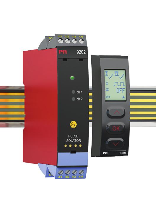
3 INTRODUCTION This configuration manual contains the necessary information for configuring a PR 9202 device which is connected to a PR 4511 Modbus RTU enabler. Modbus is a master-slave system, where the master communicates with one or multiple slaves. The master typically is a PLC (Programmable Logic Controller), DCS (Distributed Control System), HMI (Human Machine Interface), RTU (Remote Terminal Unit) or PC. The three most common Modbus versions used are: MODBUS ASCII, MODBUS RTU and MODBUS/TCP. In Modbus RTU, data is coded in binary, and requires only one communication byte per data byte. This is ideal for use over multi-drop RS485 networks, at speeds up to 115,200 bps. The most common speeds are 9,600 bps and 19,200 bps. Modbus RTU is the most widely used industrial protocol and is supported by the Modbus RTU To communicate with a slave device, the master sends a message containing: Device Address - Function Code - Data - Error Check The Device Address is a number from 0 to 247. Messages sent to address 0 (broadcast messages) will be accepted by all slaves, but numbers are addresses of specific devices. With the exception of broadcast messages, a slave device always responds to a Modbus message so the master knows the message was received Supported Modbus Function Codes Command Function code Read Holding s 03 Read Input s 04 Write Single 06 Diagnostics 08 Write Multiple s 16 The Function Code defines the command that the slave device is to execute, such as read data, accept data, report status. Some function codes have sub-function codes. The Data defines addresses in the device s memory map for read functions, contains data values to be written into the device s memory, or contains other information needed to carry out the function requested. The Error Check is a 16-bit numeric value representing the Cyclic Redundancy Check (CRC). Maximum number of registers which can be read or written at once: For a read command, the limit is 8 registers at a baud rate up to 38,400 bps, 16 57,800 bps and ,200 bps. For a write command, the limit is 123 registers at baud rates up to 115,200 bps Modbus parameter settings and default factory settings Automatic Baudrate Detection: Can be configured YES or NO Supported Baudrates: 2400, 4800, 9600, 19.2k, 38.4k, 57.6k, 115.2k bps Parity Mode: Even, Odd or None parity Stop Bits: 1 or 2 stop bits Response delay: ms (0 ms = default) Modbus slave addressing range: (247 = default address) Modbus Parameter Storage: Saved in non-volatile memory in the 4511 device (Factory Default Values are marked in bold) Modbus RTU segment line termination A 120 Ohm resistor should be installed on both ends of a RS485 Modbus RTU segment loop to prevent signal echoes from corrupting data on the line. 9202MCM101 3
4 Category Parameter Name No. Address 9202 Configuration Parameter List Size Write GENERAL DEVICE NUMBER RO GENERAL DEVICE VERSION RO GENERAL PASSWORD R/W GENERAL PASSWORD TRY R/W INDICATE SENSOR SHORTAGE INDICATE SENSOR BREAKAGE Type Description Values R/W R/W Defines the actual device number 9202 = (0x9202)) Product version 0 Password for entering configuration menu Password attempted for entering configuration menu Indicate sensor shortage via relay and/or rail. Indicate sensor breakage via relay and/or rail. RAIL ERROR R/W Indicate error on rail. CONTRAST BACKLIGHT R/W R/W LINE FUNCTION R/W GENERAL GENERAL ENABLE PASSWORD HELP TEXT LANGUAGE R/W R/W Contrast in the LCD display Backlight intensity in LCD Information shown in input line of display in monitor mode (normal mode). Password protect entry to configuration menu) Language for the help texts shown on display. GENERAL SIL ENABLE *1) RO Read SIL mode. GENERAL DEVICE TYPE RO Defines the actual device type together with the device no. (e.g. 9202B1A = 0x0B1A) Range: Range: Range: Range: TAG = 1 D.OUT = 2 ALTERNATING = 3 UK = 0 DK = 1 DE = 2 FR = 3 SE = 4 IT = 5 ES = 6 B1A = 2842 (0x0B1A) B1B = 2843 (0x0B1B) B2A = 2858 (0x0B2A) B2B = 2859 (0x0B2B) B3A = 2874 (0x0B3A) B3B = 2875 (0x0B3B) GENERAL CHANNEL 1 FUNCTION CHANNEL 1 TAG TEXT CHANNEL 2 FUNCTION CHANNEL 2 TAG TEXT Configuration counter R/W R/W ASCII CHAR R/W R/W ASCII CHAR RO Select function type for channel 1. Tag of the device channel 1 (5 characters). Select function type for channel 2. Tag of the device channel 2 (5 characters). This counter will count the number of times the configuration has been changed. The counter is reset on power-up Range: Range: INVERT = 0 DIRECT = 1 ASCII values from 32 to 90 ( to Z ) INVERT = 0 DIRECT = 1 ASCII values from 32 to 90 ( to Z ) Range *1) If SIL mode is set by an authorized SIL user (SIL ENABLE = YES), all parameters become READ ONLY MCM101
5 Parameter Name CONFIGURATION No. Address Size Write RO ERROR RO MEASURE CHANNEL 1 CHANNEL 2 MEASURE CONTROL RO RO RO R/W OUTPUT STATE R/W TIMEOUT COUNTER R/W 9202 Process Parameter List Type Description Values FAIL No valid configuration has been received OPEN Actual configuration is NOT locked (non-sil) Shows the device configuration LOCK Actual configuration is locked (SIL) according to the SIL setting. INIT Initial status after a powerup/reset until a configuration has been received CRC ERROR: bit 0 = 1 CALIBRATION ERROR: bit 1 = 1 CONFIGURATION ERROR: bit 2 = 1 Status of common errors for READ ERROR: bit 3 = 1 the device. WRITE ERROR: bit 4 = 1 SUPPLY ERROR: bit 5 = 1 CPU ERROR: bit 6 = 1 FLASH/RAM/CRC ERROR: bit 7 = 1 CH1 ENERGIZED: bit 0 = 1 CH1 BREAK DETECT: bit 1 = 1 CH1 SHORT DETECT: bit 2 = 1 Shows the device measurement status. CH1 DIRECTION: bit 3 = 1 CH2 ENERGIZED: bit 4 = 1 CH2 BREAK DETECT: bit 5 = 1 CH2 SHORT DETECT: bit 6 = 1 CH2 DIRECTION: bit 7 = 1 Shows the status ofchannel 1. FREQ. ABOVE 1Hz: bit 0 = 1 FREQ. ABOVE 5Hz: bit 1 = 1 Shows the status ofchannel 2. FREQ. ABOVE 1Hz: bit 0 = 1 FREQ. ABOVE 5Hz: bit 1 = 1 Enables simulation of Error and Rail signals. Actual setting of the signals is controlled by OUTPUT STATE. Shows status of Used to set value of the simulated process. Time-out counter which resets various bits in MEASURE CONTROL upon overflow and is automatically set to 133. Decrements once every s. RESERVED Must be set to 0 bit 0 RESERVED Must be set to 0 bit 1 Error out simulation, set by OUTPUT STATE bit 2 = 1 Rail signal simulation, set by OUTPUT STATE bit 3 = 1 RESERVED Must be set to 0 bit RESERVED Must be set to 0 bit Error out simulation value (1=OFF, 2=ON) bit 4 Rail Signal simulation value (1=OFF, 2=ON) bit 5 RESERVED Must be set to 0 bit Range: MCM101 5
6 Parameter Name No. Address 4511 Modbus Configuration Parameter List Size Write ENABLE MODBUS R/W BAUDRATE R/W ENABLE AUTOBAUD R/W Type Description Values Enable Modbus communication. If disabled, 4511 ignores all frames sent from the Modbus master and the only way to re-enable Modbus communication is by using the 4511 menu. The baud value used for Modbus communication Enable automatic baudrate detection. If enabled, 4511 determines the baud automatically by listening to frames sent on the Modbus line. PARITY R/W Configures parity check on Modbus frames STOPBITS R/W ADDRESS R/W RESPONSE DELAY R/W Configures the number of stopbits in Modbus frames Configures the Modbus address of the 4511 (Address 0 is broadcast address) Configures minimum delay for Modbus response in ms 2400 BAUD = BAUD = BAUD = BAUD = BAUD = BAUD = BAUD = 6 NONE = 0 EVEN PARITY = 1 ODD PARITY = 2 ONE STOPBIT = 1 TWO STOPBITS = 2 Range: Range: Parameter Name: Nr. Address: Size: 4511 Additional Parameter List Write: ROTATE DEVICE R/W Type: Description: Values Enables the display and key buttons to be used normally when the host device is mounted upside down Parameter Name: AUTOBAUD Nr. Address: Size: 4511 Modbus Status Parameter List Write: Type: Description: Values RO Actual state of automatic baudrate detection IDENTIFY DEVICE R/W MAXIMUM READ REGISTERS RO Enables the device to flash the LCD background with appr. 4 Hz. Value will automatically return to NO if not written within 10 seconds! Maximum allowed number of registers that can be read in one command, with the given/detected baudrate 2400 BAUD = BAUD = BAUD = BAUD = BAUD = BAUD = BAUD = 6 SEARCHING = 7 ERROR = 8 Range: MCM101
7 4511 Modbus Front Programming Parameter Menu "M" Scrolling HELP TEXTS: (correct) (NO) (YES) [1] Set correct password [2] Enter advanced setup menu [3] Perform memory operations Enter display setup Perform process calibration Enter simulation setup Enter password setup Enter language setup Enter rail setup (System 9000) Enter Modbus setup [4] Check automatic baudrate detection status Enable Modbus communication Disable Modbus communication [5] Reset Modbus to default [6] Select Modbus slave address [7] Select parity for Modbus [8] Select number of stop bits [9] Select response delay in ms [10] Enable automatic baudrate detection [11] Searching for Modbus baudrate Modbus baudrate detected Modbus baudrate not detected [12] Select baudrate in bps [13] Rotate device upside down? * 1) Only if automatic baudrate detection is enabled MODB ORIEN MEM DISP CAL SIM PASS LANG RAIL (OFF) MODB (ON) *1) Please note: If no keys are activated for 1 minute, the 4511 display will return to the Monitor view without saving. The display will aslo return to "Monitor" upon successful Modbus write command! The grayed-out menus and texts are only shown for guidance and are not a part of the 4511 specific submenu. The Modbus submenu is located in the Advanced Setting menu structure of any host device using the The actual placement is defined for each particular device. MODB (YES) (NO) *1) "M" (YES) (NO) "M" ORIEN "M" 9202MCM101 7
4511 MODBUS RTU. Configuration Manual. Solenoid / alarm driver. No. 9203MCM100(1328)
") 4511 MODBUS RTU Configuration Manual Solenoid / alarm driver 9203MCM100(1328) 9203 CONTENTS Introduction... 3 Modbus basics... 3 Modbus RTU... 3 Supported Function Codes... 3 Modbus Parameters and factory
4511 MODBUS RTU Configuration Manual Solenoid / alarm driver 9203MCM100(1328) 9203 CONTENTS Introduction... 3 Modbus basics... 3 Modbus RTU... 3 Supported Function Codes... 3 Modbus Parameters and factory
4511 MODBUS RTU. Configuration Manual. HART transparent driver. No. 9107MCM102(1739) For 4511 devices from ser. no:
 For 4511 devices from ser. no:") 4511 MODBUS RTU Configuration Manual HART transparent driver No. 9107MCM102(1739) For 4511 devices from ser. no: 141590001 9107 CONTENTS Introduction... 3 Modbus basics... 3 Modbus RTU... 3 4511 Supported
4511 MODBUS RTU Configuration Manual HART transparent driver No. 9107MCM102(1739) For 4511 devices from ser. no: 141590001 9107 CONTENTS Introduction... 3 Modbus basics... 3 Modbus RTU... 3 4511 Supported
4511 MODBUS RTU. Configuration Manual. Universal transmitter. No. 4114MCM101(1445) For 4511 devices from ser. no:
 For 4511 devices from ser. no:") 4511 MODBUS RTU Configuration Manual 4114 Universal transmitter 4114MCM101(1445) For 4511 devices from ser. no: 141590001 4114 CONTENTS Introduction... 3 Modbus basics...3 Modbus RTU...3 4511 Supported
4511 MODBUS RTU Configuration Manual 4114 Universal transmitter 4114MCM101(1445) For 4511 devices from ser. no: 141590001 4114 CONTENTS Introduction... 3 Modbus basics...3 Modbus RTU...3 4511 Supported
4511 MODBUS RTU. Configuration Manual. Universal transmitter. No. 4116MCM101(1445) For 4511 devices from ser. no:
 For 4511 devices from ser. no:") 4511 MODBUS RTU Configuration Manual 4116 Universal transmitter 4116MCM101(1445) For 4511 devices from ser. no: 141590001 4116 CONTENTS Introduction... 1 Modbus basics... 1 Modbus RTU... 1 4511 Supported
4511 MODBUS RTU Configuration Manual 4116 Universal transmitter 4116MCM101(1445) For 4511 devices from ser. no: 141590001 4116 CONTENTS Introduction... 1 Modbus basics... 1 Modbus RTU... 1 4511 Supported
4511 MODBUS RTU. Configuration Manual. Universal trip amplifier. No. 4131MCM101(1445) For 4511 devices from ser. no:
 For 4511 devices from ser. no:") 4511 MODBUS RTU Configuration Manual 4131 Universal trip amplifier 4131MCM101(1445) For 4511 devices from ser. no: 141590001 4131 CONTENTS Introduction... 1 Modbus basics... 1 Modbus RTU... 1 4511 Supported
4511 MODBUS RTU Configuration Manual 4131 Universal trip amplifier 4131MCM101(1445) For 4511 devices from ser. no: 141590001 4131 CONTENTS Introduction... 1 Modbus basics... 1 Modbus RTU... 1 4511 Supported
4511 MODBUS RTU. Configuration Manual. Universal transmitter. No. 4114MCM100(1402)
") 4511 MODBUS RTU Configuration Manual 4114 Universal transmitter 4114MCM100(1402) 4114 CONTENTS Introduction... 3 Modbus basics... 3 Modbus RTU... 3 Supported Function Codes... 3 Modbus Parameters and factory
4511 MODBUS RTU Configuration Manual 4114 Universal transmitter 4114MCM100(1402) 4114 CONTENTS Introduction... 3 Modbus basics... 3 Modbus RTU... 3 Supported Function Codes... 3 Modbus Parameters and factory
4511 MODBUS RTU. Configuration Manual. Universal trip amplifier. No. 4131MCM100(1402)
") 4511 MODBUS RTU Configuration Manual 4131 Universal trip amplifier 4131MCM100(1402) 4131 CONTENTS Introduction... 3 Modbus basics... 3 Modbus RTU... 3 Supported Function Codes... 3 Modbus Parameters and
4511 MODBUS RTU Configuration Manual 4131 Universal trip amplifier 4131MCM100(1402) 4131 CONTENTS Introduction... 3 Modbus basics... 3 Modbus RTU... 3 Supported Function Codes... 3 Modbus Parameters and
4511 MODBUS RTU. Configuration Manual. Temperaure / ma converter. No. 9113MCM100(1338)
") 4511 MODBUS RTU Configuration Manual Temperaure / ma converter 9113MCM100(1338) 9113 CONTENTS Introduction... 3 Modbus basics... 3 Modbus RTU... 3 Supported Function Codes... 3 Modbus Parameters and factory
4511 MODBUS RTU Configuration Manual Temperaure / ma converter 9113MCM100(1338) 9113 CONTENTS Introduction... 3 Modbus basics... 3 Modbus RTU... 3 Supported Function Codes... 3 Modbus Parameters and factory
Configuration Manual 4179 / 4511 Modbus RTU configuration of 4179 Universal AC/DC transmitter
 Configuration Manual 4179 / 4511 Modbus RTU configuration of 4179 Universal AC/DC transmitter PERFORMANCE MADE SMARTER TEMPERATURE I.S. INTERFACES COMMUNICATION INTERFACES MULTIFUNCTIONAL ISOLATION 4179MCM100-UK
Configuration Manual 4184 / 4511 Modbus RTU configuration of 4184 Universal uni-/bipolar signal transmitter
 PERFORMANCE MADE SMARTER Configuration Manual 4184 / 4511 Modbus RTU configuration of 4184 Universal uni-/bipolar signal transmitter TEMPERATURE I.S. INTERFACES COMMUNICATION INTERFACES MULTIFUNCTIONAL
Interface Definition RISH EM 2340/1320/30/ _Rev. D - 8/2016
 Interface Definition RISH EM 2340/1320/30/40 1 2-60-006-00-00494_Rev. D - 8/2016 2 Section DIGITAL MULTIFUNCTION INSTRUMENT Contents 1. Introduction Programmable Multi-function Energy Meter Installation
USER MANUAL. Modbus IHP24-A IHP24-AF IHP24-B IHP24-BF IHP24-F IHP24-I 1/26
 USER MANUAL Modbus IHP24-A IHP24-AF IHP24-B IHP24-BF IHP24-F IHP24-I 1/26 Table of contents 1 General... 3 1.1 Safety instructions... 3 2 Purpose... 4 3 Specifications... 5 3.1 Electrical specifications
Product Manual 4511 Communication enabler
 Product Manual Communication enabler PERFORMANCE MADE SMARTER TEMPERATURE I.S. INTERFACES COMMUNICATION INTERFACES MULTIFUNCTIONAL ISOLATION DISPLAY No. V101-UK From serial no.: 14151 6 Product Pillars
INSTRUCTION MANUAL ESI-Manager communication How to use RS485 USB Ethernet connections
 INSTRUCTION MANUAL ESI-Manager communication How to use RS485 USB Ethernet connections Table of contents 1 Introduction to this manual... 4 1.1 Intended audience... 4 1.2 Before you start... 4 1.3 How
INTELLIS. Modbus Direct Network Monitor
 INTELLIS Modbus Direct Network Monitor System Installation and Operation Manual Phone: (201) 794-7650 Fax: (201)794-0913 Chapter 1 Modbus Protocol Revision History Revision 1.0 30 April, 2002 Initial Version
Serial Connection of HC900 Hybrid Controller to 900CS Control Station
 Note: Ethernet connections will provide faster performance than RS-485 HC900 1. Remove HC900 CPU and set S2 Dip Switches for RS-485 unterminated Replace CPU & follow instructions per Installation and User
Golander Peristaltic Pump MODBUS Communication Instruction
 Golander Peristaltic Pump MODBUS Communication Instruction 1 Introduction... 1 2 Modbus Protocol... 2 2.1 Modbus Protocol Model... 2 2.2 Byte Format... 2 2.3 MODBUS Message Timing... 2 2.4 Field... 3 2.5
List of Contents 1. INTRODUCTION DEFINITIONS AND ABBREVIATIONS REFERENCES TECHNICAL DATA GENERAL MODBUS RTU...
 MAGX2 RTU User Guide -0- V1.5 23-01-2018 List of Contents 1. INTRODUCTION... 2 1.1 DEFINITIONS AND ABBREVIATIONS... 2 1.2 REFERENCES... 2 2. TECHNICAL DATA... 3 2.1 GENERAL MODBUS RTU... 4 3. COMMISSIONING...
SE-330 SERIES (NEW REVISION) MODBUS/TCP INTERFACE
 MODBUS/TCP INTERFACE") Tel: +1-800-832-3873 E-mail: techline@littelfuse.com www.littelfuse.com/se-330 SE-330 SERIES (NEW REVISION) MODBUS/TCP INTERFACE Revision 0-E-121117 Copyright 2018 Littelfuse Startco Ltd. All rights reserved.
Tel: +1-800-832-3873 E-mail: techline@littelfuse.com www.littelfuse.com/se-330 SE-330 SERIES (NEW REVISION) MODBUS/TCP INTERFACE Revision 0-E-121117 Copyright 2018 Littelfuse Startco Ltd. All rights reserved.
Real Time Clock with Temperature Sensor and RS485/Modbus Comunications
 Real Time Clock with Temperature Sensor and RS485/Modbus Comunications April 29, 2014 Power 8 20 VDC @ less than 100 MA. Battery connect jumper RS485 Bus Load Jumpers Model: RTC-TI2C Page 1 of 6 Features:
CURRENT PROTECTION RELAY SMPR-1
 CURRENT PROTECTION RELAY SMPR-1 1.- ORION ITALIA SERIES MODBUS PROTOCOL. The ORION ITALIA SERIES implement a subset of the AEG Modicon Modbus serial communication standard. Many devices support this protocol
SPM90 MODBUS PROTOCOL AND REGISTER LIST V1.0
 SPM90 MODBUS PROTOCOL AND REGISTER LIST V1.0 目 录 1. Introduction... 1 1.1 Purpose of the Communication Protocol... 1 1.2 Version of Communication Protocol... 1 2. Detailed Description of the SPM90 Modbus
Communications guide. Line Distance Protection System * F1* GE Digital Energy. Title page
 Title page GE Digital Energy D90 Plus Line Distance Protection System Communications guide D90 Plus firmware revision:.9x GE publication code: 60-9070-F (GEK-3469) GE Digital Energy 650 Markland Street
Intech Micro 2300-A8VI analogue input station MODBUS RTU slave application supplementary manual.
 Intech Micro 2300-A8VI analogue input station MODBUS RTU slave application supplementary manual. MODBUS supplementary manual to the 2300-A8VI Installation Guide. The 2300 series stations are designed to
INSTRUCTION MANUAL RVT communication How to use RS485 USB Ethernet RVT connections
 INSTRUCTION MANUAL RVT communication How to use RS85 USB Ethernet RVT connections Table of contents 1 Introduction to the controller... 1.1 Intended audience... 1.2 Before you start... 1.3 How to use this
IFC 100 Supplementary instructions
 IFC 100 Supplementary instructions Signal converter for electromagnetic flowmeters Description of Modbus interface Electronic Revision: ER 3.0.xx Modbus version: 1.0.xx KROHNE CONTENTS IFC 100 1 Important
ICC. Modbus RTU Sniffer Driver Manual INDUSTRIAL CONTROL COMMUNICATIONS, INC Industrial Control Communications, Inc.
 INDUSTRIAL CONTROL COMMUNICATIONS, INC. Modbus RTU Sniffer Driver Manual April 3, 2017 2017 Industrial Control Communications, Inc. TABLE OF CONTENTS 1 Modbus RTU Sniffer... 2 1.1 Overview... 2 1.2 Sniffer
General Specifications
 General Specifications and Server Communication Communication 1. General The protocol can be used for DCS communication for the and analyzer server. This communication protocol was first established for
Clear Benefits of the KRAL Electronic.
 Clear Benefits of the KRAL Electronic. Coordinated to the flowmeters and their applications. Users of conventional universal display units often cannot make use of their device s options. There is often
BQ & BQ370-01N MODBUS ANALOG INPUT DEVICE USER MANUAL
 BQ370-01 & BQ370-01N MODBUS ANALOG INPUT DEVICE USER MANUAL (Modbus PT Temperature Sensor Reader) Document Version 1.2.0 Content Content 2 About BQ370 Device Family 3 About Device 3 Device Properties 4
SMARTRAIL X100 Protocol
 Smart Process & Control Ltd 11 Totman Close Brook Road Industrial Estate Rayleigh, Essex SS6 7UZ Customer Service: 01268 773422 www.smartprocess.co.uk SMARTRAIL X100 Protocol 1. SMARTRAIL X100 Protocol
1.Eastron SDM230Modbus Smart Meter Modbus Protocol Implementation V1.2
 1.Eastron SDM230Modbus Smart Meter Modbus Protocol Implementation V1.2 1.1 Modbus Protocol Overview This section provides basic information for interfacing the Eastron Smart meter to a Modbus Protocol
Product Specification for SAB-S-MODBUS
 SAB-S-MODBUS May 9, 2011 Product Specification for SAB-S-MODBUS The SAB-S-MODBUS is a two-channel module that measures single or multiple magnet transducer position and returns this information to a host
This command can be used for reading the current state of one or several digital inputs, according to the table below.
 Digital Counter Input Module COMMUNICATION MANUAL INTRODUCTION The DigiRail-4C is provided with RS485 two wire serial communication, operating as slave in the Modbus RTU protocol. The entire equipment
1.Eastron SDM530-Modbus Smart Meter Modbus Protocol Implementation V1.1
 1.Eastron SDM530-Modbus Smart Meter Modbus Protocol Implementation V1.1 1.1 Modbus Protocol Overview This section provides basic information for interfacing the Eastron Smart meter to a Modbus Protocol
DTU sensor data formats.
 DTU sensor data formats. 1. DTU sensor supports four different software protocols over RS-485 LSit, Omnicomm-2, Omnicomm-3, Modbus RTU. At one time the DTU runs only one protocol. The selection of desired
Flex Series User Guide
 User Programmable Current 4..20mA Digital RS485 Dual & Single Axis Up to 360º 2016 Flex Series User Guide Sensor Installation, Wiring, Flexware App Instructions Page 1 of 33 Page 2 of 33 Table of Contents
8 data bits, least significant bit sent first 1 bit for even/odd parity (or no parity) 1 stop bit if parity is used; 1 or 2 bits if no parity
 1 stop bit if parity is used; 1 or 2 bits if no parity") 1 Eastron SDM630 Smart Meter Modbus Protocol Implementation V1.2 1.1 Modbus Protocol Overview This section provides basic information for interfacing the Eastron Smart meter to a Modbus Protocol network.
1 Eastron SDM630 Smart Meter Modbus Protocol Implementation V1.2 1.1 Modbus Protocol Overview This section provides basic information for interfacing the Eastron Smart meter to a Modbus Protocol network.
Tongta Inverter TDS-F8
 Tongta Inverter TDS-F8 MODBUS Communication Application Manual Please ensure the user gets this manual, for the optimal use of this device. 1. Introduction: TEK-DRIVE / TDS-F8 INVERTER MODBUS Communication
Intech Micro 2300-RO4 analogue input station MODBUS RTU slave application supplementary manual.
 Intech Micro 2300-RO4 analogue input station MODBUS RTU slave application supplementary manual. MODBUS supplementary manual to the 2300-RO4 Installation Guide. The 2300 series stations are designed to
Intech Micro 2300-RTD6 analogue input station MODBUS RTU slave application supplementary manual.
 Intech Micro 2300-RTD6 analogue input station MODBUS RTU slave application supplementary manual. MODBUS supplementary manual to the 2300-RTD6 Installation Guide. The 2300 series stations are designed to
Revision 1.2. July 24, COM Protocol Manual. for MDC and ADC N 11th St - San Jose CA
 Revision 1.2 July 24, 2017 COM Protocol Manual for MDC and ADC www.mountztorque.com - 1080 N 11th St - San Jose CA 95112-408.292.2214 1 1 Overview and Communication Specifications 1.1 Overview If the PC
PowerLogic ION6200 Serial Communications Protocol and ION / Modbus Register Map
 70022-05-XX PROTOCOL DOCUMENT 04/2007 PowerLogic ION6200 Serial Communications Protocol and ION / Modbus Register Map This document explains the Modbus protocol on the ION6200 meter. The ION6200 meter
A36D/TPSD DNP 3.0 & Modbus SCADA INTERFACE
 SCADA INTERFACE INSTRUCTIONS - OPTION 21P / 21Q - FOR A36D/TPSD SYSTEMS A36D/TPSD DNP 3.0 & Modbus SCADA INTERFACE OPTION 21P / 21Q INSTRUCTIONS This manual is only valid for A36D/TPSD Chargers equipped
EGW1-IA3-MB User s Manual
 www.exemys.com Rev. 0 1 Products are in constant evolution to satisfy our customer needs. For that reason, the specifications and capabilities are subject to change without prior notice. Updated information
WRC Modbus to DeviceNet Gateway for GPD 506/P5
 Introduction This document describes the recommended method to configure and connect Western Reserve Controls (WRC) Modbus to DeviceNet gateway for use with the GPD 506/P5. There currently are three types
Automatic transfer switch
 Automatic transfer switch Modbus communication Protocol LINE 1 LINE 2 Q1 LOAD Q2 AUT RESET OFF _ OK MENU MENU AUT + MAN IR COM IEC 60947-6-1 Part. LE09507AA_EN-09/16-01 GF Automatic transfer switch EN
Iso DIN. User Manual. 1 channel Earth Fault Monitoring
 Page 1 of 5 2017 03 20 User Manual Iso DIN Iso DIN User Manual 1 channel Earth Fault Monitoring Megacon AB Ranhammarsvägen 20 S 168 67 Bromma Sweden Tel: 08 402 42 50 sales@megacon.se www.megacon.se eee
Trident and Trident X2 Digital Process and Temperature Panel Meter
 Sign In New User ISO 9001:2008 Certified Quality System Home Products Online Tools Videos Downloads About Us Store Contact Policies Trident and Trident X2 Digital Process and Temperature Panel Meter Products
Modbus TCP Client Ethernet Modbus TCP Client Modbus TCP Server Ethernet Modbus TCP Server 5
 Chapter 1 Connection Table Selecting RTU Master or TCP Client for the Communication Driver allows the user to use the 1:N Communication function ( Chapter 6 Communication with Multiple External Devices
Masibus Automation And Instrumentation Pvt. Ltd.
 Operator s Manual DIGITAL CONTROLLER 5006H Masibus Automation And Instrumentation Pvt. Ltd. B/30, GIDC Electronics Estate, Sector-25, Gandhinagar-382044, Gujarat, India Ph: 91 79 23287275-79 Fax: 91 79
High Voltage DC Meter
 High Voltage DC Meter Javelin D PD644 0-300 VDC input NEMA 4X, IP65 front Scale in engineering units Sunlight readable LED display 4-20 ma analog output Two form C 3 A relays option RS-485 serial communications
KTA-250 Anemometer Alarm Card
 Connects to Davis Instruments DS7911 Anemometer Monitor both the wind speed and direction Interface to PLCs using the Modbus protocol Communicate via RS232 or 2-wire RS485 Interface to PLCs/Instruments
VPGate Manual PROFIBUS to serial
 VPGate Manual PROFIBUS to serial Important information Purpose of the Manual This user manual provides information how to work with the VPGate PROFIBUS to serial. Document Updates You can obtain constantly
HIGH-VOLTAGE DC METER
 HIGH-VOLTAGE DC METER Javelin D PD644 0-300 VDC input NEMA 4X, IP65 front Scale in engineering units Sunlight readable LED display 4-20 ma analog output Two form C 3 A relays option RS-485 serial communications
INTEGRA DL1 DUAL LOAD DIGITAL METER COMMUNICATIONS GUIDE DIGITAL ENERGY METER FOR MULTIPLE LOADS IN AN ELECTRICAL SYSTEM
 DL1 INTEGRA DL1 DUAL LOAD DIGITAL METER COMMUNICATIONS GUIDE DIGITAL ENERGY METER FOR MULTIPLE LOADS IN AN ELECTRICAL SYSTEM Contents 1 Dual Load Digital meters Modbus Protocol implementation 3 1.1 Modbus
DRS-100-3P MID Energy Meter Direct Connect, 100A, Three phase Communications Guide
 DRS-100-3P MID Energy Meter Direct Connect, 100A, Three phase Communications Guide Contents 1 DRS-100-3P - Modbus Protocol Implementation 3 1.1 Modbus Protocol Overview 3 1.2 Modbus Protocol Input Registers
THERMOSALD ISX RS485 MODBUS (V5) 3E S.r.l. - Via del Maccabreccia 37/a LIPPO DI CALDERARA (BOLOGNA) THERMOREGULATOR for PULSE WELDING
 3E S.r.l. - Via del Maccabreccia 37/a LIPPO DI CALDERARA (BOLOGNA) THERMOREGULATOR for PULSE WELDING") THERMOREGULATOR for PULSE WELDING THERMOSALD ISX ADDRESS OF UNITS WITH DIP SWITCHES ADDRESS OF UNITS FROM 1 TO 255 BROADCASTING ADDRESS = 0 CONNECTION OF 3E PANEL UP TO 255 UNITS CHANGE ALL VARIABLE FROM
THERMOREGULATOR for PULSE WELDING THERMOSALD ISX ADDRESS OF UNITS WITH DIP SWITCHES ADDRESS OF UNITS FROM 1 TO 255 BROADCASTING ADDRESS = 0 CONNECTION OF 3E PANEL UP TO 255 UNITS CHANGE ALL VARIABLE FROM
AP25-3DO PROTOCOL. Modbus Guide - Issue 1.0 SUBJECT TO CHANGE WITHOUT NOTICE
 MODBUS PROTOCOL IMPLEMENTATION AP25-3DO www.sifamtinsley.co.uk NEW PRODUCT Multifunction Meters Transducers & Isolators Temperature Controllers Converters & Recorders Digital Panel Meters Current Transformers
GNM3D Series COMMUNICATION PROTOCOL. Version 1 Revision 0
 GNM3D Series COMMUNICATION PROTOCOL Version 1 Revision 0 Index 1.1 1.2 Introduction... 3 MODBUS functions... 3 1.2.1 Function 03h (Read Holding Registers)... 3 1.2.2 Function 04h (Read Input Registers)...
General Specifications
 General Specifications GC8000 Modbus Communication GS 11B08B02-01E 1. GENERAL The Modbus protocol is used for DCS communication with the GC8000. This communication protocol was first established for the
MODBUS Protocol for MiCOM P30 Series
 MODBUS Protocol for MiCOM P30 Series Substation Protocols Technical Documentation This document does not replace the Technical Manual Version: MiCOM P30, MODBUS Index: B Release: 08 / 2011 MODBUS Protocol
12-36 VDC/12-24 VAC Power Option 4-Digit Display, 0.56 (14.2 mm) or 1.20 (30.5 mm)
 or 1.20 (30.5 mm)") 4-20 ma & Relay Output Features 4-20 ma, ± 10 V, TC & RTD Inputs 12-36 VDC/12-24 VAC Power Option 4-Digit Display, 0.56 (14.2 mm) or 1.20 (30.5 mm) 24 VDC @ 200 ma Transmitter Power Supply Options Type
4-20 ma & Relay Output Features 4-20 ma, ± 10 V, TC & RTD Inputs 12-36 VDC/12-24 VAC Power Option 4-Digit Display, 0.56 (14.2 mm) or 1.20 (30.5 mm) 24 VDC @ 200 ma Transmitter Power Supply Options Type
Modbus Remote Communication Protocol for REM 54_. Technical Description
 Modbus Remote Communication Protocol for REM 54_ 1MRS 750781-MUM Issued: 08.03.2002 Version: A/18.06.2002 Checked: ML Approved: AF Remote Communication Protocol for REM 54_ Modbus We reserve the right
isma-b-mg-ip User Manual Global Control 5 Sp. z o.o. Poland, Warsaw
 isma-b-mg-ip User Manual Global Control 5 Sp. z o.o. Poland, Warsaw www.gc5.pl Table of content 1 Introduction... 4 1.1 Revision history... 5 1.2 Safety rules... 5 1.3 Technical specifications... 6 1.4
SKD-005-M Protocol. 2 RS485 General Information 2.1 Half Duplex 2.2 Connecting the Instruments 2.3 A and B terminals 2.
 Controlin BV Glasblazerstraat 1 2984 BL Ridderkerk Customer Service: +31 (0)180 330 522 www.controlin.nl SKD-005-M Protocol 1. SKD-005-M Protocol Implementation 1.1 Modbus Protocol Overview 1.2 Input register
Chaper 1: E10+ PLCs Host-Link Command Format
 Chaper 1: E10+ PLCs Host-Link While an E10+ programmable logic controller is running, a host computer can send commands in the form of ASCII strings to the controller to read or write to the inputs, outputs,
Simplified information where and how you want it.
 ConsolIdator 4 & 8 Multi-channel controllers Simplified information where and how you want it. ConsoliDator 4 Model PD940 ConsoliDator ConsoliDator 4 Features Four 4-20 Inputs Four 4-20 Outputs ConsoliDator
I/O Module. Modbus Manual DMB Series.
 I/O Module Modbus Manual DMB Series www.drago-automation.de Before Startup When operating the signal converter, certain parts of the module can carry dangerous voltage! Ignoring the warnings can lead to
MDC 700 Series User Manual
 MDC 700 Series User Manual November 2014, Version 1.00 The MDC 700 series module is a Modbus Data Concentrator that has the ability to communicate with up to 127 Modbus slave devices using Modbus RTU protocol.
EM210 COMMUNICATION PROTOCOL. Version 3 Revision 3
 EM210 COMMUNICATION PROTOCOL Version 3 Revision 3 November 13 th, 2015 Index 1.1 Introduction... 3 1.2 MODBUS functions... 3 Function 03h (Read Holding Registers)... 3 Function 04h (Read Input Registers)...
Model IR4000M. Multi-Point Monitor Modbus programming guide
 Model I4000M Multi-Point Monitor Modbus programming guide The information and technical data disclosed in this document may be used and disseminated only for the purposes and to the extent specifically
Installation and Programming Manual. Niobrara Research & Development Corporation P.O. Box 3418 Joplin, MO USA
 DUCM DF1 Manual DUCM DF1 Installation and Programming Manual This manual describes the DUCM application for interfacing DF1 slaves to a Modbus or RNIM serial network. Effective: February 16, 2017 Niobrara
DTSX3000 Communications(Modbus) Guide
 Guide") User s Manual DTSX3000 Communications(Modbus) Guide First Edition Blank Page < Introduction > i Introduction About this Manual Thank you for purchasing the DTSX3000 Distributed Temperature Sensor. This
User s Manual DTSX3000 Communications(Modbus) Guide First Edition Blank Page < Introduction > i Introduction About this Manual Thank you for purchasing the DTSX3000 Distributed Temperature Sensor. This
Setting the DCM Switches
 20 The device(s) connected to the DCM will help you determine the appropriate switch settings. Host Computer or Operator Interface Connection If you re using a host computer or operator interface as the
Embedded Modbus TCP Module GS11-MT. User Manual REV 1.1. SST Automation.
 Embedded Modbus TCP Module GS11-MT User Manual REV 1.1 SST Automation E-mail: SUPPORT@SSTCOMM.COM WWW.SSTCOMM.COM Catalog 1 About the Embedded Module... 4 1.1 General...4 1.2 Features... 4 1.3 Specifications...4
17 Configuring a BM85 In this chapter
 17 Configuring a BM85 In this chapter Configuring a BM85 Bridge multiplexer 360 Configuring the Modbus ports of a BM85 362 ProWORX NxT User s Guide Configuring a BM85 Bridge multiplexer A BM85 Bridge Multiplexer
How-To. Modbus-TCP communication between CelciuX and NJ. History
 History Date Version Author Description 03.10.12 1.0 pk 1 st release 04.10.12 1.1 pk Added very important notes (tips and tricks) 22.11.12 1.2 pk Minor corrections according Thomas Grootenboers HowTo_ModbusTCP_CelciuX_NJ.docx
R1M-GH THERMOCOUPLE & DC INPUT MODULE MODEL. Remote I/O R1M Series. (16 points)
") Remote I/O R1M Series THERMOCOUPLE & DC INPUT MODULE (16 points) MODEL MODEL & SUFFIX CODE SELECTION R1MGH2T MODEL Modbus protocol I/O TYPE GH2 : Thermocouple or DC input, 16 points FIELD TERMINAL TYPE
Remote I/O R1M Series THERMOCOUPLE & DC INPUT MODULE (16 points) MODEL MODEL & SUFFIX CODE SELECTION R1MGH2T MODEL Modbus protocol I/O TYPE GH2 : Thermocouple or DC input, 16 points FIELD TERMINAL TYPE
2 Table of Contents 1. TABLE OF CONTENTS. 1. Table of Contents Introduction Wiring Diagram Terminals Review...
 TPR-6 Temperature Protection Relay Instruction Manual Ver. June 1 st 2010 2 Table of Contents 1. TABLE OF CONTENTS 1. Table of Contents... 2 2. Introduction... 3 3. Wiring Diagram... 5 4. Terminals Review...
G303 RIO (REMOTE I/O) AND LOW END RTU
 AND LOW END RTU") G3 TECHNOLOGIES, INC. G303 RIO (REMOTE I/O) AND LOW END RTU USER DOCUMENTATION / FUNCTIONAL SPEC. Introduction: The G303 is one of several RIO (Remote I/O) products from G3 Technologies designed to fill
G3 TECHNOLOGIES, INC. G303 RIO (REMOTE I/O) AND LOW END RTU USER DOCUMENTATION / FUNCTIONAL SPEC. Introduction: The G303 is one of several RIO (Remote I/O) products from G3 Technologies designed to fill
GE MDS, LLC. NETio Series. Protocol Communications Supplement. March 2013 Part No A01, Rev. C
 GE MDS, LLC. NETio Series Protocol Communications Supplement March 2013 Part No. 05-4672A01, Rev. C Modbus Protocol NETio Architectural Implementation As described in detail below, the Modbus RTU protocol
MODEL: R1M-P4. PC Recorders R1M Series. SPECIFICATIONS OF OPTION: Q COATING (For the detail, refer to M-System's web site.)
") PC Recorders Series PC RECORDER (4 totalized counter inputs, 8 contact inputs and outputs) Functions & Features Industrial recorder on PC Totalized counter inputs Counts stored in E 2 PROM Easy system
PC Recorders Series PC RECORDER (4 totalized counter inputs, 8 contact inputs and outputs) Functions & Features Industrial recorder on PC Totalized counter inputs Counts stored in E 2 PROM Easy system
Supported Modbus RTU Function Codes... 26
 å Contents Overview... 5 Introduction... 5 About This Manual... 5 Assumptions... 5 What You Should Already Know... 5 Modbus RTU Overview... 5 VLT 2800 and VLT 6000 with Modbus RTU... 6 Installation and
EM210 COMMUNICATION PROTOCOL. Version 3 Revision 1
 EM210 COMMUNICATION PROTOCOL Version 3 Revision 1 June 4 th, 2014 Index 1.1 Introduction...3 1.2 MODBUS functions...3 Function 03h (Read Holding Registers)...3 Function 04h (Read Input Registers)...4 Function
TRAINING GUIDE LEVEL 3 MODBUS WRITE IMPORT COMMAND
 OleumTechTM TRAINING GUIDE LEVEL 3 MODBUS WRITE IMPORT COMMAND MUST BE FAMILIAR WITH LEVEL 1 TRAINING MATERIALS BEFORE MOVING FORWARD Doc ID# 80-6010-001b TABLE OF CONTENTS 1. WHAT IS NEW WRITE IMPORT
Operating Instructions. Modbus RTU VLT 2800 VLT 6000 VLT 8000
 Operating Instructions Modbus RTU VLT 2800 VLT 6000 VLT 8000 Contents Overview... 6 Introduction... 6 About This Manual... 6 Assumptions... 6 What You Should Already Know... 6 Modbus RTU Overview... 6
JUMO di 308. Digital Indicator. B Interface Description Modbus 12.07/
 JUMO di 308 Digital Indicator B 70.1550.2.0 Interface Description Modbus 12.07/00485372 Contents 1 Introduction 5 1.1 Preface... 5 1.2 Typographical conventions... 6 1.2.1 Warning signs... 6 1.2.2 Note
How to set-up and read MOBBUS
 How to set-up and read MOBBUS Before anything can be read from the RTU, the meter must be programmed. During programming up to 16 of the thousands of displays in the meter can be assigned to the RTU. The
ETC II Modbus Communications Protocol Reference Guide
 ETC II Modbus Communications Protocol Reference Guide SATEC Ltd. BG0595 Rev. A1 Every effort has been made to ensure that the material herein is complete and accurate. However, the manufacturer is not
ELECTRONIC METER SX1-A31E MODBUS RTU Protocol Specifications MDD-T0025A
 ELECTRONIC METER SX1-A31E MODBUS RTU Protocol Specifications SPEC. NO. : MDD-T0025A MITSUBISHI ELECTRIC AUTOMATION (THAILAND) CO., LTD CONTENTS 1. Functions 2 2. Checking before usage... 2 3. System Configurations.
Carbon Monoxide Transmitter
 Introduction The CO Transmitter uses an electrochemical sensor to monitor the carbon monoxide level and outputs a fieldselectable 4-20 ma or voltage signal. The voltage signal may also be set to 0-5 or
Version Action Author Date
 Version Action Author Date 1.0 Initial document KP 25.08.2013 1.1 Document review, description and register update GP 26.08.2013 1.2 Status bits, current noise floor GP 29.08.2013 1.3 Using EG100 as a
EM21 COMMUNICATION PROTOCOL. Version 1 Revision 0
 EM21 COMMUNICATION PROTOCOL Version 1 Revision 0 April 7 th, 2008 Index 1.1 Introduction...3 1.2 MODBUS functions...3 1.2.1 Function 03h (Read Holding Registers)...3 1.2.2 Function 04h (Read Input Registers)...4
EM100 Series and ET100 Series
 EM100 Series and ET100 Series COMMUNICATION PROTOCOL Version 2 Revision 6 Index 1.1 1.2 Introduction... 3 MODBUS functions... 3 1.2.1 Function 03h (Read Holding Registers)...3 1.2.2 Function 04h (Read
Modbus RTU/TCP Installation and Programming Guide PC3400 Particle Counter
 Chemtrac, Inc. Modbus RTU/TCP Installation and Programming Guide PC3400 Particle Counter Chemtrac, Inc. rev. B111811 Introduction This guide is for use with Chemtrac s PC 3400 D Particle Counters. The
ATK3 I/O Module (Modbus Slave)
") ATK3 I/O Module (Modbus Slave) 2011-01-13 The ATK3 I/O Module by ElectroCom Table of contents 2011-01-13...1 The ATK3 I/O Module by ElectroCom...1 1 Hardware...2 1.1 Inputs...3 1.2 Outputs...3 1.2.1 Relay...3
ATK3 I/O Module (Modbus Slave) 2011-01-13 The ATK3 I/O Module by ElectroCom Table of contents 2011-01-13...1 The ATK3 I/O Module by ElectroCom...1 1 Hardware...2 1.1 Inputs...3 1.2 Outputs...3 1.2.1 Relay...3
Chapter. Modbus. In This Chapter...
 Modbus Communication Chapter 7 In This Chapter... Modbus Protocol....7 2 Registers....7 2 Connection with the DirectLOGIC PLC....7 8 Connection with the C-more and C-more Micro HMI panels....7 10 Modbus
FIOD 0808 Manual. The FIOD series products add digital capability to your PLC / SCADA.
 The FIOD series products add digital capability to your PLC / SCD. FIOD 0808 model has 8 digital inputs and 8 relay / transistor (PNP/NPN) outputs. The digital inputs and outputs are isolated from the
Intrinsically Safe Temperature Concentrator System
 Intrinsically Safe Temperature Concentrator System Up to 32 Channels per Network HART and PC configurable 2, 3 & 4-wire RTD or Thermocouple Transmitter like Sensor Diagnostics and performance, RTD ±0.1