GILLIG ELECTRIC BUS Diagnostic Software User Guide & Troubleshooting Guide 8A Rev C Last Revised: 3/23/2017
|
|
|
- Steven Tyler
- 5 years ago
- Views:
Transcription

1 GILLIG ELECTRIC BUS Diagnostic Software User Guide & Troubleshooting Guide 8A Rev C Last Revised: 3/23/2017
2 Table of Contents Section 1: Introduction... 2 Connector Definitions... 2 Location of Connectors... 6 Section 2: rmal Operating Conditions... 9 E-Bus On... 9 Fan Operation Fan # Layout... 9 Diagnostic Bulb Reverse Switch (use to check if all fans are working) Section 3: Failsafe Feature Operating Conditions Section 4: Diagnostic Software Supported Devices Downloading Diagnostic Software Connecting to Built-in Diagnostic System Manual Control Interpreting Data Downloading Data Log Data Log Triggers Section 5: Troubleshooting Fans Do t Run When They Are Supposed To Fans Run When They Are t Supposed To or Failsafe Features Activated Under or Over Voltage Level at Controller Fan Failure High Controller Internal Temperature CAN Communication Loss Appendix B J1939 Messages DM1 Fault Messages Performance Messages System Identification Revision Log /26


3 Section 1: Introduction This guide instructs users of the Modine EFAN system on how to connect to its diagnostic system, download data logs, monitor current status, and troubleshoot potential problems. This troubleshooting guide applies to EFAN systems with the following controller Part Numbers: PR Gillig Electric Bus System Controller Connector Definitions # Name Description Pictoral 1. Square RS232 RS232 connector used for connecting to controller for firmware re-programming and datalog downloading 2. Fuse & Holder Fan (30A) 30A fuse to protect wires to each individual E-fan and E-Pump 3. Fuse & Holder Controller (5A) 5A fuse to protect wires to controller 4. HDP Power & Ground (see below) HDP Connector used for connecting power and ground wires to and from E-fans and E- Pump 5. Flat 6-pin 6. J1939 (CAN) Pin A - Ignition, Red - Input Pin B - Reverse, Blue - Input Pin C - Fire, Purple - Input Pin D Status to Diagnostic Bulb, Brown - Output Pin E - Ground, Black J1939 (CAN) connection between E-fan Cooling Module and bus interface 2/26


4 7. Controller Connector 30 pin 8. Controller Connector 18 pin 9. Busbar Radiator Ground Busbar used to connect all radiators to ground 3/26


5 10. Busbar (PWM) EFAN Troubleshooting Guide Latest Revision: 3/2/2017 Busbar used to connect PWM output from controller to bank of E-fans. One busbar for PCS/APS fan bank and for ACTM/WAVE fan bank Busbar (Ignition Failsafe) Fan Connector Fan Side (4100 RPM Fan) Fan Connector Harness Side (4100 RPM Fan) Busbar used to connect vechicle ignition input and provide output to controller, each individual E-fan and each individual E- pump. Pin E Power, Red Pin G Ground, Black Pin B PWM, Yellow Pin C Fault / Diagnostic Wire, White Pin F Ignition Failsafe, Red or Black Pin E Power, Red Pin G Ground, Black Pin B PWM, Yellow Pin C Fault / Diagnostic Wire, White Pin F Ignition Failsafe, Red or Black 14. Pump Connector Power Pump Side Pin #1 t Used, Plugged Pin #2 Ground, Black Pin #3 Power, Red Pin #4 Operation Enable, Red 15. Pump Connector CAN Pump Side Pin #1 CAN High, Yellow Pin #2 CAN Shield Pin #3 t Used, Plugged Pin #4 CAN Address Pin #5 CAN Address Pin #6 CAN Low, Green Pump Connector Power Harness Side Pump Connector CAN Harness Side Pin #1 t Used, Plugged Pin #2 Ground, Black Pin #3 Power, Red Pin #4 Operation Enable, Red Pin #1 CAN High, Yellow Pin #2 CAN Shield Pin #3 t Used, Plugged Pin #4 CAN Address Pin #5 CAN Address Pin #6 CAN Low, Green 4/26


6 18. Radiator Ground Harness Side EFAN Troubleshooting Guide Latest Revision: 3/2/2017 Radiator Ground 19. Radiator Ground Radiator Side Radiator Ground 20. Controller Main system controller. Controller part # printed on front label. 21. Diagnostic Bulb / Reverse Switch Typically provided by OEM OEM rear run box typically includes reverse switch and diagnostic bulb together in rear run box panel 5/26

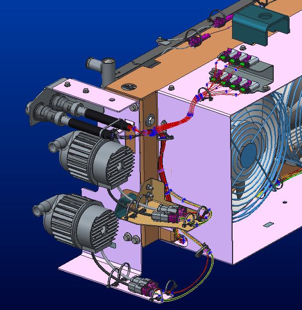
7 Location of Connectors EFAN Troubleshooting Guide Latest Revision: 3/2/2017 6/26

8 7/26
9 8/26
10 Section 2: rmal Operating Conditions rmal system response can be verified by the E-bus on conditions below and by running the reverse sequence. E-Bus On 1. WAVE/ACTM and PCS/APS Fans OFF with no cooling demand 2. Diagnostic bulb illuminates for the first 3 seconds to indicate controller power is on and then remains off Fan Operation Fan # Layout Wave / ACTM (RAD) fans Do not run until % Fan Request from 18E0FF66 or 18E0FF80 is greater than 0% PCS/APS (RAD) fans Do not run until % Fan Request from 18E0FF03 is greater than 0% te: All Wave / ACTM fans turn on together at the same speed when commanded and all PCS / APS fans turn on together at the same speed when commanded. 9/26
 have failed.")
11 Diagnostic Bulb EFAN Troubleshooting Guide Latest Revision: 3/2/2017 Bulb State Meaning Off System is running normally On CAN communication with module has been lost Flashing 1 second on, 1 second off Fans running in reverse sequence, use to check bulb Flashing Long and short duration Indicates which fan(s) have failed. Short flashes indicate fan number, multiple numbers are separated by long pause On for 3 seconds during initial Indicates controller is powered on. Light must turn controller power up off after initial startup te: See Troubleshooting Section if CAN Communication is lost or a fan failure has occurred. Reverse Switch (use to check if all fans are working) Press switch momentarily to activate reverse sequence. Fans will run in reverse for about 15 seconds. Diagnostic bulb will flash during this time. This sequence may be aborted by pressing switch again. te: ignition must be on and the fire override (gravity switch on fan door, if installed by OEM, and any other fire override inputs from fire suppression system or IO multiplexer that OEM uses) must be off to run reverse sequence. This may be accomplished by keeping fan door closed or temporarily disconnecting switch. 10/26
12 Section 3: Failsafe Feature Operating Conditions Two failsafe feature operating conditions were put in place to protect the vehicle from an overheat event. These are not normal operating conditions and require further troubleshooting if they occur. 1. CAN Communication Loss Protection Controller will request fans to run at a default speed near full speed. 2. Ignition Failsafe Loss Protection In the event that the controller fails or loses power and the ignition wire to the fans is +24V the fans will run at a default speed near full speed. Section 4: Diagnostic Software The Modine Universal Diagnostic Software (UDS) package has the following functions: Monitor system response in real time Control cooling module manually Download internal data log (RS-232 cable required, Modine PN: 3S ) Supported Devices All RP1210 compliant J1939 data link adapters are supported. Examples include the NexIQ USB-Link (PN: ) and the Cummins INLINE 6 (PN: ). Downloading Diagnostic Software 1. Enter (or click) the following address in your default internet browser: a. Or you can perform the following steps. i. Navigate to ii. Navigate to Products > Transit Bus tab iii. Click on Troubleshooting & Diagnostics on the left side of the screen. iv. Click the Transit Diagnostic Software Link 2. Download and run the setup.exe file. 3. There should now be a Modine UDS program in your Start Menu. Connecting to Built-in Diagnostic System 1. Make sure the latest version of Modine UDS is installed on computer that will be used for troubleshooting. See previous section. 2. Connect one of the supported data link adapters, outlined above. Drivers must be obtained through the manufacturer s website and installed. 3. Launch Modine UDS and turn on vehicle to power up controller. 4. If this is the first time running Modine UDS with a given datalink adapter: a. Select the Connect RP1210 Adapter button. 11/26


13 b. A dialog will appear. First select the Manufacturer driver, then the Device connected to the PC. This list is populated with all drivers installed on the PC. c. Press OK to confirm selection. If connection is unsuccessful, another selection may be attempted. If connection is successful, Modine UDS will remember the selection and automatically connect the last successful device when the program is run again. 5. The bottom of the main window will display connection status along with controller part number and revision level. See image below. Controller part # below shown for reference only. 6. The EFAN system status may now be monitored, fans may be manually controlled, and histogram data may be downloaded (if equipped). 12/26

14 Manual Control 1. To enable manual control, check the box next to Manual Control. The fan speed will now reflect the fan speed entered in the boxes below (0-100%). 2. The fans will run at the nearest increment to the entered value. te that this will likely not reflect the exact value entered. If a Percent Fan Request from the E-bus reaches 100, manual mode will be disabled until temperatures decrease. 3. Once the Manual Mode check box is unchecked, fans will resume normal operation. 13/26


15 Interpreting Data 1. Gauges that are grey indicate that there is no J1939 message present. 2. Red fan gauges indicate a fan failure. In this case, fan 3 is failed and fan 4 is operating correctly. 3. Any active DM1 fault messages will be displayed in the message box at the bottom of the screen. 14/26


16 Downloading Data Log 1. If Windows does not recognize the USB diagnostic cable, download the driver here: 2. Open Modine UDS 3. With the controller on, connect the USB diagnostic cable 4. Click the Download Fault Log button near the bottom of the screen. 5. Select the COM port assigned to the cable. 6. When data has been successfully downloaded, a CSV file with the time/date of download will be placed in C:\ModineFaultLogs\ Data Log Triggers If any of the triggers listed below occur, the controller will record a log file that can be downloaded for diagnostic and system analysis See Section 5: Troubleshooting - Failure Reported Via CAN or Controller Data log for troubleshooting activities. Trigger Under or Over Voltage at Controller Fan Failure High Controller Temp CAN Communication loss Condition Voltage at controller is < 16 VDC or > 32 VDC One or more fans are not running when they should be Internal controller temperature is greater than 176 F (80 C) CAN/J1939 cable disconnected from controller 15/26
17 Section 5: Troubleshooting Fans Do t Run When They Are Supposed To Possible Cause Remedy See Flowchart below for step-by-step diagnosing Fire Override Active (+24 V on Pin C of 6 pin). Tilt switch active (if present). Fire override active from IO multiplexer/fire suppression input. Incorrect PWM output from controller (3% is Off, 40% is min speed, 92% is max speed) Blown fan fuse or OEM module fuse. Replace fire override tilt switch. Consult OEM Troubleshoot CAN Connection. Replace controller. Replace blown fuse. Fan(s) not receiving +24V Inspect HDP power & ground connection to make sure all wires are seated properly and connector seats completely. Loss of ground connection Reported fan failure when fan is operating normally Failed fan wiring or fan motor Corrosion on fan connector wires. Inspect HDP power & ground connection to make sure all wires are seated properly and connector seats completely. Corrosion on fan connector wires. If no continuity exists on white diagnostic wire between fan and controller. Ensure all connectors are connected correctly. If continuity exists on white diagnostic wire between fan and controller. Apply +24V to power and PWM cavities and ground to ground cavity of individual fan. Wait 15 seconds; fan should begin to spin near full speed. Clean wires and replace terminals, seals and connectors as needed. Replace fan, bad internal power/ground or PWM connection. te: Use RTMD real time data monitoring / download data files and OEM reverse feature function as needed for diagnosing. 16/26
18 Fans do not run when they are supposed to EFAN Troubleshooting Guide Latest Revision: 3/2/2017 Check fan fuses and OEM module fuse Check busbar caps Checklist for fans to run +24V on Power (thicker red wire on fan connector) 0V on Ground (black wire on fan connector) +24V on Ignition (thinner red wire on fan connector) +24V for full speed on PWM (yellow wire on fan connector) fans run Some fans run Reverse feature is a good way to test functionality Diagnostic line (white wire) outputs +24V when fan is running Fan ignition wire- if 0V is present on fan ignition cavity and vehicle ignition and controller are both on, fan will operate in normal condition. 0V on fan ignition cavity means ignition failsafe feature in the event of a controller failure, is disabled. Does diagnostic light flash once per second when reverse switch is activated and ignition is on Repair reverse switch. Blue wire. Ensure it supplies 24V to controller when thrown. Also ensure diagnostic light is functioning Is Fire Override activate? Disconnect the fire override switch connector (if equipped) Consult OEM/ troubleshoot fire suppression system or IO multiplexer Failed fans correspond to a fan bank? Is there +24V on fan connector ignition line when vehicle ignition is on? Inspect ignition connection on flat 6-pin connector and ignition busbar Is controller PWM output correct? Next Page Is there +24V on the fan connector power line? Trace power lines back to vehicle connection check fuses and depending on model either: A) ensure HDP connector is properly seated or B) ensure ring terminals are secure and clean Troubleshoot CAN Communication or Replace Controller 17/26
19 Replace fan (bad internal diagnostic wire). Inspect HDP Power & Ground connection. Make sure all wires are seated and connected properly Is there continuity between fan connector diagnostic wire and controller 30-pin connector? Replace terminals and seals (as needed). Do the fans in question run appropriately? Does reported fan failure go away? Use external diagnostic bulb/uds to verify. Replace terminals and seals (as needed). Inspect fan connector. Look for corrosion or loose terminals Fan functionality may be checked by applying system voltage (usually +24V) to fan power wire and PWM wire and ground to fan ground wire. Fan should run near full speed. te: Swapping a fan that runs with a fan that does not run will determine if the failed condition follows the wire harness or the specific fan. Run reverse feature for quick feedback on fan performance. Replace Fan Does fan run? Replace terminals, seals and connectors (as needed). 18/26
20 Fans Run When They Are t Supposed To or Failsafe Features Activated Possible Cause Remedy Loss of fan ground connection Fan not receiving PWM output from controller CAN Communication Loss Controller not receiving +24V (+/- 5 volts) Failed Controller Voltage on fan PWM wire when vehicle ignition is off See Flowchart below for step-by-step diagnosing Inspect HDP power & ground connection to make sure all wires are seated properly and connector seats completely. Corrosion on fan connector wires Check continuity on PWM wire from fan to PWM busbar to controller PWM output cavity and ensure all connectors are properly seated. Check voltages at 5A fuse, Ignition busbar, flat 6-pin (pin A). Verify +24V (+/- 5 volts) volts is across pins H2 (30 pin) and F1 (18 pin) and that 18 and 30 pin connectors are properly seated. Check individual fan connectors and PWM busbars for water penetration or corrosion. Verify greater than 0V exists on fan PWM wire when PWM busbar is removed. Clean wires and replace terminals, seals and connectors. Clean wires and replace terminals, seals, connectors and PWM busbar caps as needed. See CAN Communication Loss troubleshooting section. Replace 5A fuse, ignition busbar, wiring harness or wiring harness section. Clean wires and replace terminals, seals and connectors as needed Replace controller Clean wires and replace terminals seals and connectors. 19/26
21 Replace Controller Fans run when they are not supposed to 24V (+/-5V) between controller pins 30-H2 and 18- F1? Make sure 30 and 18- pin connectors are clean and secure to controller. CAN communication failsafe has occurred Is green controller LED On? Inspect HDP Power & Ground connection. Make sure all wires are seated and connected properly Check ground wire connection. Flat 6-pin connector or ring terminal at OEM chassis ground. Replace 5A fuse, PWM busbar, wiring harness or wiring harness section (as needed). Does an entire bank of fans continue to run? Check 5A controller fuse Is there +24V on each of the components? Disconnect PWM busbars and ignition busbar to determine which individual fan runs by itself. 24V (+/-5V) between controller pins 30-H2 and 18- F1? Make sure 30 and 18- pin connectors are clean and secure to controller. Check voltage at 5A fuse, PWM busar and ignition wire on flat 6-pin connector Do any fans continue to run? Inspect connector on fans that continue to run. Look for water creating a connection between the red ignition or power wires and the yellow PWM wire. Verify greater than 0V exists on PWM line. Verify system operates normally. Reinstall PWM and ignition busbars. Inspect for continuity between PWM busbar and individual fan PWM wire. Make sure all connectors are sealed and connected correctly. Reinstall PWM and ignition busbars. Inspect for continuity between PWM busbar and controller PWM output. Make sure all connectors are sealed and connected correctly. Replace terminals, seals and connectors (as needed). 20/26
22 Failure Reported Via CAN or Controller Data Log The following are the current controller recognized fault codes for the internal data logger: The trigger that created the data log file is located at the bottom row of the log event. te: Controller can store roughly 100 events and they are first in first out. Trigger Under or Over Voltage at Controller Fan Failure High Controller Temp CAN Communication loss Condition Voltage at controller is < 16 VDC or > 32 VDC One or more fans are not running when they should be Internal controller temperature is greater than 176 F (80 C) CAN/J1939 cable disconnected from controller Under or Over Voltage Level at Controller Possible Cause Remedy See Flowchart below for step-by-step diagnosing Controller not receiving +24V Inspect ignition connection on 6-pin vehicle connector Loss of ground connection Poor voltage regulator/battery charging system Inspect ground connection on 6-pin vehicle connector. Trace back to bus ground and troubleshoot. Troubleshoot voltage regulator/battery charging system. Consult OEM. te: If the red LED illuminates and the data trigger occurs directly after startup and the system is running normal, allow system to charge, key ignition off and restart to remove red LED light. 21/26
23 Under or Over Voltage Level at Controller Inspect IGNITION wire on flat 6-pin vehicle connector Inspect GROUND wire on flat 6-pin vehicle connector Troubleshoot IGNITION source/connection Is there +24V on IGN line? Is there -24V on GROUND line? Troubleshoot GROUND source/connection Troubleshoot voltage regulator/battery charging system. Consult OEM Is the voltage regulator and/or battery charging system operating correctly? Replace terminals and seals on flat 6-pin IGN/GND 22/26
24 Fan Failure When a fan failure is reported in the log file, review the Fan # Status columns to determine which fan failure location has been identified. A value of 1 means the fan it working, a value of 0 indicates a fan fault. See the Fans Do t Run When They are Supposed To Section for further troubleshooting. High Controller Internal Temperature Possible Cause Remedy See Flowchart below for step-by-step diagnosing Excessive hot air recirculation Controller improperly mounted Inspect cooling system air seals near controller. Inspect mounting of controller and match location listed in Location of Connectors section Consult OEM to eliminate air recirculation. Secure controller in original location. Faulty controller circuitry Replace controller. Reported High Internal Controller Temperature Is there excessive hot air recirculation coming from the engine compartment? Is the controller mounted correctly and in appropriate location? Secure controller correctly Consult OEM to eliminate air recirculation Replace controller 23/26
25 CAN Communication Loss Possible Cause Remedy See Flowchart below for step-by-step diagnosing Loose CAN connection at controller External CAN device interference Inspect 3-way Deutsche CAN connector Vehicle ECU Incorrectly configured for E-fan Replace terminals, seals and connectors. Troubleshoot CAN network. Consult OEM Troubleshoot ECU to accept variable speed fan. Consult OEM. Receive CAN Communication Loss error from controller or CAN system Make sure: 3-pin triangle connector is secured Terminating resistor is installed in Y- connector, if equipped Check input statuses using RTMD Test for short circuit: Voltage between +24V (battery voltage) and CAN HIGH and CAN LOW should be between 0 and battery voltage Test with ignition on battery connected Test for open circuit: Resistance on CAN network should be 60 +/- 6 Ohms test with Ignition off and battery disconnected Is CAN communication functioning? Inspect 3-pin triangle CAN connector Check for external devices on CAN network that may disturb controller function Ensure vehicle ECU is properly configured for EFAN system Consult OEM 24/26
26 Appendix B J1939 Messages DM1 Fault Messages Fault Type Source Description J1939 SPN J1939 FMI Fan 1 Inoperable Fan 2 Inoperable Diagnostic Fan 3 Inoperable feedback from fan Fan 4 Inoperable motor indicates Fan Motor Fan 5 Inoperable that fan blades are Fan 6 Inoperable not spinning when Fan 7 Inoperable commanded to Fan 8 Inoperable Fan 1 J1939 Failsafe Mode Fans are running Fan 2 J1939 Failsafe Mode properly but Fan 3 J1939 Failsafe Mode operating Fan 4 J1939 Failsafe Mode conditions form Controller Fan 5 J1939 Failsafe Mode the vehicle CAN Fan 6 J1939 Failsafe Mode bus have been lost Fan 7 J1939 Failsafe Mode Fans are running at Fan 8 J1939 Failsafe Mode failsafe speed Voltage at the Controller system controller Over-Voltage above 32V Voltage at the Controller system controller Under-Voltage below 17V Fire Override input Controller Fire Override Active is active Reverse Active Controller Controller is in reverse sequence J1939 Lamp ne Diagnostic Lamp Flash corresponding to failed fan number Internal Data log trigger? ne Solid ON ne ne ne ne ne ne ne Flash at 1 Hz during sequence Performance Messages Description Pri PGN SA Byte [1-8] Factor Offset Units Rate [ms] PWM % - Fan Bank 1 18 B100 4E % 1000 PWM % - Fan Bank 2 18 B200 4E % 1000 PWM % - Fan Bank 3 18 B300 4E % 1000 tes Minimum fan speed = 40% PWM Maximum fan speed 90% PWM System Identification Description Pri PGN SA Rate Length [bytes] Data Request message 18 EA4E Any N/A 3 18 EA 00 Controller Part Number 18 FEDA 4E On Request 8 Byte 2-6 = Last 5 digits of controller part number Firmware Revision 18 FEDA 4E On Request 8 Byte 7 = Firmware revision 25/26
27 Revision Log Revision Description Date CR A Released to production. 10/10/16 NA B Updated title page, added DM1 and J1939 messages 3/2/ C Removed Common Service Parts Appendix 3/23/ /26
Additions, Revisions, or Updates
 1 3 39-12 SUBJECT DATE SPN 625/FMI 2 and 9 (ACM2.1) April 2012 Additions, Revisions, or Updates Publication Number / Title Platform Section Title Change DDC-SVC-MAN-0084 MY13 DD Platform SPN 625/FMI 2
MTX-D Ethanol Content and Fuel Temperature Gauge User Manual
 MTX-D Ethanol Content and Fuel Temperature Gauge User Manual P/N 3912 kit does not include flex fuel sensor. The ECF-1 is compatible with GM P/Ns 13577429 and 13577379 1. Installation... 2 1.1 Gauge Mounting...
Procedure revision date: 03/19/2013
 2010 Explorer 2010 PCED Gasoline Engines SECTION 5: Pinpoint Tests Report a problem with this article Procedure revision date: 03/19/2013 KD: Electric Exhaust Gas Recirculation (EEGR) System KD: Introduction
PEM Faults and Blower Failures
 CHAPTER 2 The following sections provide methods for troubleshooting faults involving the Cisco 10000 series router Power Entry Modules (PEMs) and blower modules. This chapter contains the following major
WARNING!!!!!!!!! IMPORTANT INFORMATION: READ BEFORE INSTALLATION!
 V_Net Relay Module Installation Instructions: Part Number: 230-VM-RELAY WARNING!!!!!!!!! IMPORTANT INFORMATION: READ BEFORE INSTALLATION! The relay outputs of the 230-VM-RELAY module may turn on when not
Additions, Revisions, or Updates
 10 20-13 1 10 20-13 SUBJECT DATE SPN 1071/FMI 3,4,5 - EPA10 - GHG14 (MCM) October 2013 Additions, Revisions, or Updates Publication Number / Title Platform Section Title Change DDC-SVC-MAN-0084 DD Platform
TD-700 FLUOROMETER SERVICE MANUAL
 TD-700 FLUOROMETER SERVICE MANUAL July 1996 CONTENTS Page Section 1 INTRODUCTION 2 Section 2 PRELIMINARY CHECKS 3 Section 3 TROUBLESHOOTING GUIDE 5 A. Lamp (Fluorescent) 5 B. Lamp Heater 7 C. Fan 8 D.
This is an inspection failure, not meeting the requirement of >10k Ohm between either PD battery post and chassis.
 Troubleshooting This is a document put together by CSA Laura Rhodes that contains a lot of information about troubleshooting steps for a lot of common control system problems encountered at events. No
MTX-A Temperature Gauge User Manual
 MTX-A Temperature Gauge User Manual 1. Installation... 2 1.1 Gauge Mounting... 2 1.2 Temperature Sensor Mounting... 2 1.2.1 Changing the MTX-A s Gauge Bezel... 2 1.3 Main Gauge Wiring... 3 1.3.1 Single
Installation Instructions
 Installation Instructions USM 4 Sensor Input Vnet Module Racepak PN: 230-VM-USM Racepak Data Systems 30402 Esperanza Rancho Santa Margarita, CA 92688 949-709-5555 www.racepak.com Table of Contents PRODUCT
PDC-X Digital Controller
 Operator s Manual LOR Manufacturing PDC-X Digital Controller Publication PDC_X_MAN_02252015_US Version 1.0.1-1-gfdf1ed4 Copyright 2015 Thoroughly read and understand all information presented in this
Lightning Stitch Assembly
 ABM International, Inc. 1 1.0: Parts List Lightning stitch motor and drive assembly (Qty. 1) Lightning stitch piggy backed controller board assembly (Qty. 1) Touchscreen (Qty. 1) 2 9-pin Serial cable (Qty.
SECTION B: Anti-Theft Passive Anti-Theft System (PATS) DIAGNOSIS AND TESTING Procedure revision date: 05/23/2008
 DIAGNOSIS AND TESTING Procedure revision date: 05/23/2008") SECTION 419-01B: Anti-Theft Passive Anti-Theft System (PATS) 2009 Mustang Workshop Manual DIAGNOSIS AND TESTING Procedure revision date: 05/23/2008 Anti-Theft Special Tool(s) 73III Automotive Meter 105-R0057
SECTION 419-01B: Anti-Theft Passive Anti-Theft System (PATS) 2009 Mustang Workshop Manual DIAGNOSIS AND TESTING Procedure revision date: 05/23/2008 Anti-Theft Special Tool(s) 73III Automotive Meter 105-R0057
Integrated Battery Control System LBCS Step-by-Step Setup Guide
 Integrated Battery Control System LBCS Step-by-Step Setup Guide 1. Components of the System 2. Components of the System 3. LBCS Overview 4. Battery Connections 5. Sense Board Installation 6. Sense Board
ABM International, Inc. Lightning Stitch Checklist 9/13/2013
 ABM International, Inc. Lightning Stitch Checklist 9/13/2013 1) Piggy backed board assembly (1) Piggy back board assembly tested? Yes No 24v passed XB passed XA passed YB passed YA passed SAFE passed S/S
DC3IOB Revision User Guide Updated 3/29/10. Overview
 Revision 080910 User Guide Updated 3/29/10 Overview The is a three axis DC brush motor drive with an integrated PLC. A range of motor drive currents are selectable with jumper blocks. The integrated PLC
USB-Link 2 Vehicle Interface Installation and Setup Manual
 USB-Link 2 Vehicle Interface Installation and Setup Manual Chapter 1: Introducing the USB-Link 2...1 Component Checklist...2 Product Specifications...3 System Requirements...4 Communication Options: Wired
TECHNICAL DATASHEET #TDAX050000K CAN
 This cost-effective, compact and robust CAN display shows machine, engine and transmission operating parameters and service codes. Enhanced operating information made available to a vehicle operator improves
TECHNICAL PRODUCT DATASHEET
 FORM-ENG-0018 REV A 06-02-03 ISO 9001 CERTIFIED Phone: (352) 629-5020 or 800-533-3569 Fax: (352)-629-2902 SUITABLE FOR EXTERNAL DISTRIBUTION TECHNICAL PRODUCT DATASHEET ES-Key Climate Control Module P/N
Installation Instructions
 Installation Instructions This document provides information on: important pre-installation considerations power supply requirements installing the module connecting the wiring using the indicators for
MasterFlux 48V Cascade BLDC Motor Controller Product Specification 030F0137
 MasterFlux 48V Cascade BLDC Motor Controller Product Specification 030F0137 Revision History Page 1 of 11 Date ECN Rev Description By 09/01/10 EC34869 A Initial Release D. Stahl 07/14/11 EC39745 B Updated
FAULT CODE 426. SAE J1939 Data Link Communication
 Page 1 of 6 FAULT CODE 426 SAE J1939 Data Link Communication Overview CODE REASON EFFECT Fault Code: 426 PID: S231 SPN: 639 FMI: 2/2 LAMP: None SRT: Communication between the electronic control module
ISO 9001 CERTIFIED. 607 NW 27th Ave Ocala, FL Phone: (352) or Fax: (352) SUITABLE FOR EXTERNAL DISTRIBUTION
 or Fax: (352) SUITABLE FOR EXTERNAL DISTRIBUTION") ISO 9001 CERTIFIED Phone: (352) 629-5020 or 800-533-3569 Fax: (352)-629-2902 ES-Key 12- Relay Board P/N 103190 and 103338 PAGE 1 of 13 1. REVISI LOG... 2 2. OVERVIEW... 3 2.1. PART NUMBERS... 3 2.2. MODULE
ISO 9001 CERTIFIED Phone: (352) 629-5020 or 800-533-3569 Fax: (352)-629-2902 ES-Key 12- Relay Board P/N 103190 and 103338 PAGE 1 of 13 1. REVISI LOG... 2 2. OVERVIEW... 3 2.1. PART NUMBERS... 3 2.2. MODULE
Troubleshooting CHAPTER
 CHAPTER 1 1 1 1 0 1 1 0 1 1 0 1 1 0 1 1 0 1 1 0 1 1 0 1 1 1 0 1 6 0 1 1 0 1 1 0 1 0 1 10 1 0 1 1 0 1 0 1 1 0 1 0 1 1 0 1 10 Troubleshooting NOTICE: Information in this manual may change without notice.
Software... pg3 File Maintenance Training
 V-MUX Installation Practices March 2010 1 V-MUX Installation Practices Software...... pg3 File Maintenance Training Electrical...... pg3 Circuit breakers or Fuse protection 3 Power to Nodes 3 Ground to
WVL2 Wireless Vehicle Link 2 Installation and Setup Manual
 WVL2 Wireless Vehicle Link 2 Installation and Setup Manual Chapter 1: Introducing the Wireless Vehicle Link 2...1 WVL2 Components...2 Component Checklist...3 Product Specifications...4 System Requirements...5
What s in the Box? REAR VIEW SAFETY
 TM 1 What s in the Box? 1 Full HD Color Infra-red Weather Proof Camera 1 Full HD 7" TFT LCD Color Monitor w/monitor Mount 1 Power Harness 1 66 Camera Cable 1 Power Connection Wire 1 Screw Kit for installation
Instruction and Operations Manual
 1 GARTECH Enterprises, Inc. Rev 2 01-23-09 Instruction and Operations Manual Portable Test Cell Overview The primary purpose of the Portable Test Cell is to allow the user the ability to control the engine
Troubleshooting Guide for Firecom Intercoms
 A) I have a problem with Interior Communications - Headset to Headset I cannot communicate between headsets and I cannot hear myself in my own headset. I cannot communicate between headsets but I do hear
DirectCommand Installation RoGator Model Year Ag Leader Technology
 Note: Indented items indicate parts included in an assembly listed above Part Name/Description Part Number Quantity Direct Command Kit 4100801 1 Dual Lock 2000052-9 1 Dual Lock 2000053-9 1 Quick Reference
Heated Oxygen Sensor (HO2S )
") Page 1 of 11 Year = 2011 Model = Mustang Engine = 5.0L VIN = IDS Version = t Available Heated Oxygen Sensor (HO2S ) WARNING: Crown Victoria Police Interceptor vehicles equipped with fire suppression system,
Page 1 of 11 Year = 2011 Model = Mustang Engine = 5.0L VIN = IDS Version = t Available Heated Oxygen Sensor (HO2S ) WARNING: Crown Victoria Police Interceptor vehicles equipped with fire suppression system,
Troubleshooting the System Hardware
 CHAPTER 5 This chapter provides basic troubleshooting information to help you identify some common problems that might occur with your Wide Area Virtualization Engine (WAVE). This chapter contains the
RTK3 Logic Controller User Manual Revised
 RTK3 Logic Controller User Manual Revised 6-24-08 1 of 16 svn://software/hardware/rtk3/docs/rtk3_man.doc MRR 6/24/08 9:03 AM Overview The RTK3 is intended to simplify and expedite control wiring. Centroid
Instruction Manual. M Pump Motor Controller. For file reference, please record the following data:
 Instruction Manual M Pump Motor Controller For file reference, please record the following data: Model No: Serial No: Installation Date: Installation Location: When ordering replacement parts for your
An ISO 9001:2008 Registered Company
 An ISO 9001:2008 Registered Company Upfitter Interface Module The following list represents firmware v4.30 A-UIM4-506-A 2011-2016 Ford F250-550 B-UIM4-506-A 2017 F250-F550 A-UIM4-751-A 2013-2017 1500-5500
WOODINVILLE, WA SUPERSTEP 2100 SERIES SEQUENCING PROPORTIONAL LOAD CONTROLLERS INSTALLATION & OPERATING MANUAL. Models: SLC2102-SLC2112
 SELECTRONIX, INC. WOODINVILLE, WA SUPERSTEP 2100 SERIES SEQUENCING PROPORTIONAL LOAD CONTROLLERS INSTALLATION & OPERATING MANUAL Models: SLC2102-SLC2112 SLC2102X-SLC2112X SLC2152-SLC2162 SLC2170-xx Relay
Part Number N AEM 4-CH WIDEBAND UEGO CONTROLLER WITH NASCAR SPEC ECU CAN CONFIGURATION
 Part Number 30-2340-N AEM 4-CH WIDEBAND UEGO CONTROLLER WITH NASCAR SPEC ECU CAN CONFIGURATION FIGURE 1. WIRING DIAGRAM AEM 4 CH UEGO Controller Parts 1 x 35-2340 4 CH UEGO Module 1 x 35-2908 Wiring Harness
The GENIE Light Kit is ideal for introducing simple lighting projects, such as an electronic die, a wearable badge or a night-time warning system.
 Introduction 1 Welcome to the GENIE microcontroller system! The GENIE Light Kit is ideal for introducing simple lighting projects, such as an electronic die, a wearable badge or a night-time warning system.
Introduction of Au SAE J1939 Simulator Gen II 1.00A and 2.00A
 Introduction of Au SAE J1939 Simulator Gen II 1.00A and 2.00A Au SAE J1939 Simulator Gen II (Figure 1), a family of well designed devices, is capable of simulating majority of SAE J1939 signals on a SAE
User s Guide. LA5034 Operation Manual
 User s Guide LA5034 Operation Manual Content General safety summary... I Introduction... II Chapter 1 Getting started... 1 System Requirements... 2 Installing Hardware... 3 Installing Software... 6 User
e-ask electronic Access Security Keyless-entry OEM / Dealer / Installer Cargo Lock / Unlock Version Installation & Instructions (UM04 ~ )
") e-ask electronic Access Security Keyless-entry OEM / Dealer / Installer Cargo Lock / Unlock Version Installation & Instructions (UM04 ~ 18990-04) Table of Contents Introduction... 1 e-fob Operation and
e-ask electronic Access Security Keyless-entry OEM / Dealer / Installer Cargo Lock / Unlock Version Installation & Instructions (UM04 ~ 18990-04) Table of Contents Introduction... 1 e-fob Operation and
Modem Installation and Networking Instructions
 Modem Installation and Networking Instructions P/N 36870 Rev F Introduction The following instructions cover connecting a phone line to an incoming phone source, installing a modem, and setting up a network
Digital Dash I/O Adapter Configuration
 Digital Dash I/O Adapter Configuration The I/O Adapter adds ten inputs/outputs to the 7 digital dash. These inputs and outputs can then be configured as gauges or switches, and data logged locally through
Sensacell Troubleshooting Guide
 A ONLY SOME MODULES LIGHT UP B PANEL DOES NOT LIGHT UP Only some modules light up Panel does not light up Check jumpers and power wiring AC Power present at Power Supply input terminals? Check AC Line
SMM501/501-H (Surveillance Mode Module) Ford Police Interceptors (Sedan and SUV)
 Ford Police Interceptors (Sedan and SUV)") An ISO 9001:2008 Registered Company SMM501/501-H (Surveillance Mode Module) 2013-2014 Ford Police Interceptors (Sedan and SUV) Introduction The SMM501/501-H is intended for 2013 and 2014 Ford Police Interceptors
An ISO 9001:2008 Registered Company SMM501/501-H (Surveillance Mode Module) 2013-2014 Ford Police Interceptors (Sedan and SUV) Introduction The SMM501/501-H is intended for 2013 and 2014 Ford Police Interceptors
Sierra Dual 24 Volt Brushless DC Motor Controller Product Specification. Assembly 025F0348
 Sierra Dual 24 Volt Brushless DC Motor Controller Product Specification Assembly Revision History ECN # Date Rev Description By EC77363 03/15/17 A Initial Release K. Jones EC81620 11/15/17 B Added Agency
ISO 9001 CERTIFIED. 607 NW 27th Ave Ocala, FL Phone: (352) or Fax: (352) OPERATION MANUAL
 or Fax: (352) OPERATION MANUAL") ISO 9001 CERTIFIED Phone: (352) 629-5020 or 800-533-3569 Fax: (352)-629-2902 ES-Key 18 Input module (selectable polarity) with 3 outputs (selectable polarity) with 1 analog (selectable 0-5V or 4-20mA)
ISO 9001 CERTIFIED Phone: (352) 629-5020 or 800-533-3569 Fax: (352)-629-2902 ES-Key 18 Input module (selectable polarity) with 3 outputs (selectable polarity) with 1 analog (selectable 0-5V or 4-20mA)
Two Module Development Kit Installation and User Instructions For Model No. ED-GV15/30
 Two Module Development Kit Installation and User Instructions For Model No. ED-GV15/30 This Kit is designed to be used as a development platform; performance, regulatory or safety testing for commercial
INSTALLATION AND OPERATING INSTRUCTIONS DSST SYSTEM
 INSTALLATION AND OPERATING INSTRUCTIONS DSST SYSTEM PROPORTIONAL and NON-PROPORTIONAL TOGGLE SWITCH RADIO REMOTE CONTROL SYSTEM MODEL FHSTP/DSSTP SERIES FHST/DSST SYSTEM DESCRIPTION The DSST Wireless Control
00 05 Aug. 22, , Service
 Subject: Model(s): Side Airbag, On Board Diagnostic (OBD) All 2000, 2001 Group: Number: Date: 01 00 05 Aug. 22, 2000 Service Additional diagnostic procedures have been established to prevent improper replacement
Vector Drive - Troubleshooting Guide
 Haas Technical Documentation Vector Drive - Troubleshooting Guide Scan code to get the latest version of this document Translation Available The Haas Vector drive is the source of power for the spindle
Kodiak Mobile INTELLIGENT DOCKING STATION USERS MANUAL PART NUMBER: PANASONIC CF53 TOUGHBOOK COMPATIBLE AN ISO 9001:2008 CERTIFIED COMPANY
 CUSTOMER SERVICE If you have any questions or require additional information please contact Customer Service at 877-455-6886, Monday though Friday, 8:00am - 5:00pm CST. TECHNICAL SUPPORT Kodiak Mobile
Manual# Installation Manual. 200E Series. DCU 210E/208E Engine Panel RP 210E/220E Remote Panel
 Manual# 1006495 Installation Manual 200E Series DCU 210E/208E Engine Panel RP 210E/220E Remote Panel Installation Manual for the Marine Pro 200E Series ~~~ DCU 210E/208E Diesel Engine Control Unit RP 210E/220E
CONCEPT P/N: AX Concept TECHNICAL DATASHEET #TDAX Analog Input CAN Controller CAN (SAE J1939 or CANopen ) with Electronic Assistant
 with Electronic Assistant") Concept TECHNICAL DATASHEET #TDAX030400 6 Analog Input CAN Controller CAN (SAE J1939 or CANopen ) with Electronic Assistant Features: 6 analog inputs (0-5V, 0-10V, 0-20mA, 4-20mA, Resistance, PWM, Digital,
Concept TECHNICAL DATASHEET #TDAX030400 6 Analog Input CAN Controller CAN (SAE J1939 or CANopen ) with Electronic Assistant Features: 6 analog inputs (0-5V, 0-10V, 0-20mA, 4-20mA, Resistance, PWM, Digital,
X/Y Issues on ASP-645-1
 X/Y Issues on ASP-645-1 Issues seen with X or Y problems: A) Table will not move in X or Y when you are using the Frame Arrow buttons on the control panel. B) On power up the control panel gives Error
D115 The Fast Optimal Servo Amplifier For Brush, Brushless, Voice Coil Servo Motors
 D115 The Fast Optimal Servo Amplifier For Brush, Brushless, Voice Coil Servo Motors Ron Boe 5/15/2014 This user guide details the servo drives capabilities and physical interfaces. Users will be able to
Expansion Unit Catalog Nos , - 152, - 153, - 154, - 156, -E157
 PRODUCT DA TA SLC 150 110 Expansion Unit Catalog Nos. 1745-151, - 152, - 153, - 154, - 156, -E157 7 : The EXpdnSiQn Unit The SLC 150 expansion unit can be used with either the SLC 150 processor unit or
DirectCommand Installation 5 Channel Spreader Control Module Technology
 DirectCommand Installation Ag Leader Technology Note: Indented items indicate parts included in an assembly listed above Part Name/Description Part Number Quantity Direct Command Kit 4100582 1 Cable Installation
DC3IOB Revision User Guide Updated 7/12/12. Overview
 DC3IOB Revision 080910 User Guide Updated 7/12/12 Overview The DC3IOB is a three axis DC brush motor drive with an integrated PLC. A range of motor drive currents are selectable with jumper blocks. The
Ordering Part Numbers: TECHNICAL DATASHEET #TDAX BLDC MOTOR CONTROLLER P/N: AX100260
 TECHNICAL DATASHEET #TDAX100260 BLDC MOTOR CONTROLLER P/N: AX100260 Variable Speed Control, Onboard Inputs 100W Nominal Output CAN SAE J1939, Rugged Packaging High Temperature Operation Developed with
GENERIC. CANbus Setup / Configuration Manual. R170 Receiver. Revised May 17, Version 3 DMAN
 GENERIC CANbus Setup / Configuration Manual R170 Receiver Revised May 17, 2006 Version 3 DMAN - 2866-01 #74-1833 Coast Meridian Road, Port Coquitlam, BC, Canada V3C 6G5 Ph# (604) 944-9247 Fax# (604) 944-9267
ISO 9001 CERTIFIED. 607 NW 27th Ave Ocala, FL Phone: (352) or Fax: (352) OPERATION MANUAL
 or Fax: (352) OPERATION MANUAL") ISO 9001 CERTIFIED Phone: (352) 629-5020 or 800-533-3569 Fax: (352)-629-2902 ES-Key 16 Output module (selectable polarity) P/N 610-00031 PAGE 1 of 10 1. REVISION LOG... 1 2. MODULE OVERVIEW... 2 2.1. SCOPE...
ISO 9001 CERTIFIED Phone: (352) 629-5020 or 800-533-3569 Fax: (352)-629-2902 ES-Key 16 Output module (selectable polarity) P/N 610-00031 PAGE 1 of 10 1. REVISION LOG... 1 2. MODULE OVERVIEW... 2 2.1. SCOPE...
Troubleshooting in navigation system 2
 Page 1 of 7 Pin assignments, functions etc. apply to vehicles of the series E38 and E39 with navigation system 2 (as from production break PU 97) Introduction The navigation system is a dynamic system
MAINTENANCE MANUAL. EDACS REDUNDANT POWER SUPPLY SYSTEM 350A1441P1 and P2 POWER MODULE CHASSIS 350A1441P3, P4, AND P5 POWER MODULES TABLE OF CONTENTS
 MAINTENANCE MANUAL EDACS REDUNDANT POWER SUPPLY SYSTEM 350A1441P1 and P2 POWER MODULE CHASSIS 350A1441P3, P4, AND P5 POWER MODULES TABLE OF CONTENTS SPECIFICATIONS*... 2 INTRODUCTION... 3 DESCRIPTION...
DTC P0335 CKP Sensor A Circuit Performance
 2000 Cadillac DeVille DTC P0335 CKP Sensor A Circuit Performance Circuit Description The PCM uses dual crankshaft position (CKP A and CKP B) sensors to determine crankshaft position. The PCM supplies an
MTX-A, Fuel Pressure Gauge PSI
 MTX-A, Fuel Pressure Gauge 0-100 PSI Contents 1 Mounting and Sensor Installation... 2 1.1 Gauge Mounting... 2 1.1.1 Changing the MTX-A s Gauge Bezel... 2 1.2 Fuel Pressure Sensor... 2 2 Wiring... 3 2.1
ETM-2050/ETM-2051 Service Manual
 Introduction Novar s Electronic Thermostat Modules (ETMs) are intelligent control modules that provide local, direct digital control of unitary, packaged, staged HVAC systems. This document: Describes
Series F75 Fail-Safe Module Installation, Operation and Maintenance Instructions
 WCAIM2029 (Part 16022) Series F75 Fail-Safe Module Installation, Operation and Maintenance Instructions CAUTION: Flowserve recommends that all products that must be stored prior to installation be stored
HP8440 Power Box. The Intelligent Power Distribution Module. Installation and User Guide for PCM Version 9.02
 HP8440 Power Box The Intelligent Power Distribution Module Installation and User Guide for PCM Version 9.02 1 Introduction The Power Control Module is an innovative, intelligent and programmable module
CAN EGT-8 Amplifier. About:
 CAN EGT-8 Amplifier About: 1. The amplifier supports up to eight K-Type temperature probes. 2. EGT temperatures are sent to engine management ECU via CAN Bus. 3. One volt input that can be used to send
Using MDC Manager to Manage Power Settings
 AddendumA Using MDC Manager to Manage Power Settings This addendum explains how to use the MDC Manager to configure and manage the power settings for the M7. It is organized into the following sections:
Brushless DC Motor Controller Product Specification Assembly 025F0200
 Product Specification Assembly 025F0200 Revision History ECN # Date Rev Description By EC40382 071811 A Initial Release D. Stahl EC81620 11/15/17 B Added Agency Approval S. Lavey Page 1 of 11 Table Of
SCALE LINK - SL2 Technical Manual
 SCALE LINK - SL2 Technical Manual Fort Atkinson, Wisconsin USA www.digi-star.com www.topconpositioning.com/agriculture D4204-EN Rev A October 31, 2017 TABLE OF CONTENTS Reference Documents... 3 Applicable
CHAPTER 3B: ELECTRONIC POWER STEERING
 Electronic Power Steering CHAPTER 3B: ELECTRONIC POWER STEERING NOTE: The basic steering system, such as the tie rod ends, drag links axles, etc., is covered in Chapter 3A: Steering. In 2012, Cub Cadet
RTK4 Logic Controller User Manual For RTK4L Revision Revised
 RTK4 Logic Controller User Manual For RTK4L Revision 120326 Revised 6-20-12 RTK4 Features Application: PLC and Third Party Drive Interface Number of Axis Drive Interfaces: 5 Axis DAC Resolution: 16 bits
Nova Light Source Range
 Light Source User Guide Nova Light Source Range Models covered by this manual: UFO NOVA DMX UFO NOVA DMX-R UFO NOVA DMX-T UFO NOVA DMX-TR Please read this manual fully before installing, operating or performing
INSTALLATION AND MAINTENANCE INSTRUCTIONS For Chemline A- & Q-Series Actuator with Digital (AC) Positioner
 Positioner") INSTALLATION AND MAINTENANCE INSTRUCTIONS For Chemline A- & Q-Series Actuator with Digital (AC) Positioner General: The Digital High-performance position AC Controller is designed to control quarter-turn
INSTALLATION AND MAINTENANCE INSTRUCTIONS For Chemline A- & Q-Series Actuator with Digital (AC) Positioner General: The Digital High-performance position AC Controller is designed to control quarter-turn
INTELLIGENT DOCKING STATION USERS MANUAL
 Kodiak Mobile by Jotto Desk 209 W. Easy St., Rogers, AR USA 72756 Customer Service: 877.455.6886 http://www.kodiakmobile.com PART NUMBER: 450-4011 - Last Update: 06.2009 INTELLIGENT DOCKING STATION USERS
Control. Part B, Section 2. This section covers the following unit configurations. 3400V 3500V Voltage 1, 2, 3 Pump Piston (D, E, F, G)
") Part B, Section 2 Model This section covers the following unit configurations. 3100V 3400V 3500V Voltage 1, 2, 3 Pump Piston (D, E, F, G) Manifold 4-Port (A) 6-Port (B or C) 2-Port (S or T) Vista Temperature
Part B, Section 2 Model This section covers the following unit configurations. 3100V 3400V 3500V Voltage 1, 2, 3 Pump Piston (D, E, F, G) Manifold 4-Port (A) 6-Port (B or C) 2-Port (S or T) Vista Temperature
Mounting DIGITAL DISPLAY
 Mounting The Class digital display mounts in a. by. cutout. Overall area necessary for installation is. by.. Two 0.0 diameter holes are provided for mounting screws..0".0..0.900 Ø 0.0" () HOLES."." DIGITAL
OPERATING INSTRUCTIONS 7 SERIES STATIC GENERATORS
 OPERATING INSTRUCTIONS 7 SERIES STATIC GENERATORS GB Contents Page 1 Introduction 4 2 Safety 5 3 Use 6 4 Checking on Delivered Equipment 6 5 General Specification and Dimensions 7 6 Positioning 10 7 Operating
Troubleshooting a K40 Laser Power Subsystem
 Troubleshooting a K40 Laser Power Subsystem This work is licensed under a Creative Commons Attribution-onCommercial 4.0 International License. The author(s) do not make any warranties about the completeness,
Trouble Shooting Leveling Control Box Electric Jacks. Touch Pad LED Probable Cause Solution
 Trouble Shooting Leveling Control Box 140-1224 Electric Jacks Copyright Power Gear Issued: January 2013 #82-L0524, Rev. OA Touch Pad LED Probable Cause Solution 1. On/Off LED will not light 2. Wait LED
SmartFan Fusion-4. Speed Control and Alarm for DC Fans CONTROL RESOURCES INCORPORATED. The driving force of motor control & electronics cooling.
 SmartFan Fusion-4 Speed Control and Alarm for DC Fans The driving force of motor control & electronics cooling. P/N FUS300-F DC Controls SmartFan Fusion-4 is a digital fan speed control and alarm that
Introduction REAR VIEW SAFETY
 TM 1 What s in the Box? 1 Color Weather Proof Backup Camera 7" Color TFT LCD Digital Clip-on Mirror Monitor 1 3 Channel Multiplexer Control Unit 1 66 Extension Cable for Camera 1 Remote Control 1 Power
PRELIMINARY. Preliminary Technical Datasheet #TDAX Discrete I/O P/N: AX inputs, 8 relay outputs, SAE J1939 with Electronic Assistant
 Preliminary Technical Datasheet #TDAX031800 Discrete I/O P/N: AX031800 12 inputs, 8 relay outputs, SAE J1939 with Electronic Assistant Description: The Discrete I/O Module reads 12 discrete inputs and
Energy Management System. Operation and Installation Manual
 Energy Management System Operation and Installation Manual AA Portable Power Corp 825 S 19 TH Street, Richmond, CA 94804 www.batteryspace.com Table of Contents 1 Introduction 3 2. Packing List 5 3. Specifications
DirectCommand Installation RoGator 864/874/1064/1074 (MY 2006 & Earlier) Ag Leader Technology
 Ag Leader Technology") Note: Indented items indicate parts included in an assembly listed above Part Name/Description Part Number Quantity Direct Command Kit 4100524 1 Generic Cable Installation Kit 2000901-1 1 Hardware Kit
Note: Indented items indicate parts included in an assembly listed above Part Name/Description Part Number Quantity Direct Command Kit 4100524 1 Generic Cable Installation Kit 2000901-1 1 Hardware Kit
4-20 ma Output Board Dual Channel
 Honeywell Process Solutions 420 ma Output Board Dual Channel User Manual October 2010 V 2.12 Honeywell 2 www.honeywell.com Table of Contents Description...5 Principal of Operation...5 Specifications...5
12/2013. Installation Guide & User Manual
 12/2013 Installation Guide & User Manual ABOUT THIS MANUAL This manual has been written to help you understand all the functions and capabilities of the Yamaha Snowmobile Diagnostic Tool in order to gain
B&W RearView Camera Installation & Operation
 B&W RearView Camera Installation & Operation CA52 (Camera) FOR MORE INFORMATION WWW.STRATEGICVISTA.COM BEFORE OPERATING THIS SYSTEM, PLEASE READ THIS MANUAL THOROUGHLY AND RETAIN IT FOR FUTURE REFERENCE
EPS 06 in rear housing type A1
 Field Installation and / or Replacement of RACO Electronic Position Sensor Board EPS 02 & EPS 06 - Electronic Limit Switches - Analog Output Position Signal - Very Accurate - Easy To Use - Robust - Dependable
Installation Instructions for: Channel Thermocouple Amplifier
 Installation Instructions for: 30-2204 4 Channel Thermocouple Amplifier The Advanced Engine Management (AEM) 4 channel thermocouple amplifier revolutionizes temperature measurements by providing laboratory
Draper Commissioner User Manual
 Draper Commissioner User Manual Table of Contents Table of Contents...I 1. Getting Started...1 1.1 Initial Startup...1 1.2 Draper Commissioner Startup...1 1.3 Top Panel...1 2. Configuration Screens...2
Abstract. GLV User Manual 1
 GLV User Manual 1 Abstract This user manual is a high level document that explains all operational procedures and techniques needed to operate the GLV system in a safe and effective manner. Anyone operating
Nistune Type 1 Diagnostics Technical Notes V1.2 (JECS ECCS Legacy Engine Control Units)
") Nistune Type 1 Diagnostics Technical Notes V1.2 (JECS ECCS 1984-1989 Legacy Engine Control Units) Copyright 2004, 2005, 2006, 2014 Nistune Developments WARNING If your ECU pulses the fuel pump, injectors,
Nistune Type 1 Diagnostics Technical Notes V1.2 (JECS ECCS 1984-1989 Legacy Engine Control Units) Copyright 2004, 2005, 2006, 2014 Nistune Developments WARNING If your ECU pulses the fuel pump, injectors,
Operating Manual. for HXOC Page 1 of 5
 Operating Manual for HXOC-003-000-02 Page 1 of 5 ESM PROGRAMMER: OPERATING MANUAL This handheld programming device is designed for setting the two selectable operating speeds available on the ebm-papst
Brushless DC Motor Controller Product Specification Assembly 025F0095
 Product Specification Assembly 025F0095 Revision History ECN # Date Rev Description By N/A 1/23/06 1 First issue A. Meeuwsen N/A 2/07/06 2 Added content A. Meeuwsen 06008 3/13/06 A Release for document
TECHNICAL SERVICE BULLETIN
 BULLETIN: TSB-Ehubo-2017-3 DATE: November 17, 2017 SUBJECT: OBD-II BLUETOOTH PAIRING (DONGLE) DURING INSTALLATION PRODUCT / SYSTEM: EHUBO2 (North America only) BACKGROUND: Using the On-board Diagnostics
Temperature Programming Quick Reference Guide
 Temperature Programming Quick Reference Guide Normal Mode Dial Brightness (press one at a time) Peak Mode Factory Default Reset (Hold for 5 seconds) High Alert Setting Mode Use LEFT or RIGHT buttons to