Operating Instructions VLT DriveMotor FCP 106/FCM 106
|
|
|
- Kristian Carpenter
- 5 years ago
- Views:
Transcription


1 MAKING MODERN LIVING POSSIBLE Operating Instructions VLT DriveMotor FCP 106/FCM 106 vlt-drives.danfoss.com
2
3 Contents Operating Instructions Contents 1 Introduction Purpose of the Manual Additional Resources Product Overview Intended Use Electrical Overview Approvals Disposal Instruction 7 2 Safety Qualified Personnel Safety Precautions 8 3 Mechanical Installation Unpacking Items Supplied, FCP Further Items Required, FCP Items Supplied, FCM Identification of Unit Nameplates Lifting Installation Environment Mounting Introduction Prepare Gasket Prepare Adapter Plate Mount the DriveMotor Shaft Alignment Bearing Life and Lubrication 16 4 Electrical Installation Safety Instructions IT Mains EMC-compliant Installation Cable Requirements Grounding Motor Connection Connect FCP 106 to Motor Thermistor Input from Motor AC Mains Connection 24 MG03L302 Danfoss A/S 11/2015 All rights reserved. 1
4 Contents VLT DriveMotor FCP 106/FCM Control Wiring Control Terminals and Relays Control Terminals and Relays Load Sharing Brake Installation Checklist Recommendations for UL-listed PRGY Systems 28 5 Commissioning Applying Power Local Control Panel Operation Memory Module MCM Configuring with the VLT Memory Module MCM Basic Programming Configuration for Open-loop Applications Set-up Wizard for Closed-loop Applications Quick Menu Motor Set-up Changing Parameter Settings Thermistor Set-up 36 6 Maintenance, Diagnostics and Troubleshooting Maintenance List of Warnings and Alarms 37 7 Specifications Clearances, Dimensions and Weights Clearances FCP 106 Dimensions FCM 106 Dimensions Weight Electrical Data Mains Supply 3x V AC Normal and High Overload Mains Supply Protection and Features Ambient Conditions Cable Specifications Control Input/Output and Control Data Connection Tightening Torques FCM 106 Motor Specifications Fuse and Circuit Breaker Specifications 52 8 Appendix 54 2 Danfoss A/S 11/2015 All rights reserved. MG03L302
5 Contents Operating Instructions 8.1 Abbreviations and Conventions Parameter Menu Structure 54 Index 57 MG03L302 Danfoss A/S 11/2015 All rights reserved. 3
6 Introduction VLT DriveMotor FCP 106/FCM Introduction 1.1 Purpose of the Manual This manual provides information required to install and commission the frequency converter. VLT DriveMotor FCP 106 The delivery comprises the frequency converter only. A wall mount adapter plate, or motor adapter plate and power crimp terminals are also required for installation. Order the wall mount kit or adapter plate and power crimp terminals separately. VLT DriveMotor FCM 106 The frequency converter is mounted onto the motor at delivery. The combined FCP 106 and motor is known as the VLT DriveMotor FCM NA NA Illustration 1.1 FCP 106 Illustration 1.2 FCM Danfoss A/S 11/2015 All rights reserved. MG03L302
7 Introduction Operating Instructions 1.2 Additional Resources Available literature: VLT DriveMotor FCP 106/FCM 106 Operating Instructions, for information required to install and commission the frequency converter. VLT DriveMotor FCP 106/FCM 106 Design Guide provides information required for integration of the frequency converter into a diversity of applications. VLT DriveMotor FCP 106/FCM 106 Programming Guide, for how to program the unit, including complete parameter descriptions. VLT LCP Instruction, for operation of the local control panel (LCP). VLT LOP Instruction, for operation of the local operation pad (LOP). Modbus RTU Operating Instructions and VLT DriveMotor FCP 106/FCM 106 BACnet Operating Instructions for information required for controlling, monitoring, and programming of the frequency converter. The VLT PROFIBUS DP MCA 101 Installation Guide provides information about installing the PROFIBUS and troubleshooting. The VLT PROFIBUS DP MCA 101 Programming Guide provides information about configuring the system, controlling the frequency converter, accessing the frequency converter, programming, and troubleshooting. It also contains some typical application examples. VLT Motion Control Tool MCT 10 enables configuration of the frequency converter from a Windows -based PC environment. Danfoss VLT Energy Box software, for energy calculation in HVAC applications. Technical literature and approvals are available online at vlt-drives.danfoss.com/support/service/. Danfoss VLT Energy Box software is available at PC software download area. 1.3 Product Overview Intended Use The frequency converter is an electronic motor controller intended for: Regulation of motor speed in response to system feedback or to remote commands from external controllers. A power drive system consists of: - The frequency converter. - The motor. - Equipment driven by the motor. System and motor status surveillance. The frequency converter can also be used for motor overload protection. The frequency converter is allowed for use in residential, industrial, and commercial environments in accordance with local laws and standards. Depending on configuration, the frequency converter can be used in standalone applications or form part of a larger application or installation. When using a motor with thermal protection, the frequency converter is allowed for use in residential, industrial, and commercial environments in accordance with local laws and standards. Foreseeable misuse Do not use the frequency converter in applications which are non-compliant with specified operating conditions and environments. Ensure compliance with the conditions specified in chapter 7 Specifications. 1 1 MG03L302 Danfoss A/S 11/2015 All rights reserved. 5
8 Introduction VLT DriveMotor FCP 106/FCM Electrical Overview 3-phase power input L1 L2 L3 PE Located in motor block PE U V W Motor 195NA T1 T2 Thermistor located in motor UDC- UDC+ +10 V DC 0 10 V DC - 0/4 20 ma 0 10 V DC - 0/4 20 ma 50 (+10 V OUT) 53 (A IN) 54 (A IN) relay V AC 3A 55 (COM A IN/OUT) 42 0/4 20 ma A OUT/DIG OUT relay /4 20 ma A OUT/DIG OUT V AC 3A 12 (+24 V OUT) 18 (DIGI IN) 19 (DIGI IN) 20 (COM D IN) Group 5-* 24 V (NPN) 0 V (PNP) 24 V (NPN) 0 V (PNP) Bus ter. 1 2 ON 01 ON=Terminated OFF=Unterminated 27 (DIGI IN) 29 (DIGI IN) 24 V (NPN) 0 V (PNP) 24 V (NPN) 0 V (PNP) Bus ter. RS485 Interface (N RS485) 69 (P RS485) 68 (Com RS485) 61 RS485 PROFIBUS (PNP)-Source (NPN)-Sink MCM Illustration 1.3 Electrical Overview 6 Danfoss A/S 11/2015 All rights reserved. MG03L302
9 Introduction Operating Instructions 1.4 Approvals 1 1 Certification FCP 106 FCM 106 EC Declaration of Conformity UL listed UL recognized C-tick The EC declaration of conformity is based on the following directives: Low Voltage Directive 2006/95/EC, based on EN (2007). EMC Directive 2004/108/EC, based on EN (2004). UL listed Product evaluation is complete and the product can be installed in a system. The system must also be UL listed by the appropriate party. UL recognized More evaluation is required before the combined frequency converter and motor can be operated. The system in which the product is installed must also be UL listed by the appropriate party. The frequency converter complies with UL 508C thermal memory retention requirements. For more information, refer to the section Motor Thermal Protection in the product-specific design guide. 1.5 Disposal Instruction Equipment containing electrical components must not be disposed of together with domestic waste. It must be separately collected with electrical and electronic waste according to local and currently valid legislation. MG03L302 Danfoss A/S 11/2015 All rights reserved. 7
10 Safety VLT DriveMotor FCP 106/FCM Safety The following symbols are used in this manual: WARNING Indicates a potentially hazardous situation that could result in death or serious injury. CAUTION Indicates a potentially hazardous situation that could result in minor or moderate injury. It can also be used to alert against unsafe practices. NOTICE Indicates important information, including situations that can result in damage to equipment or property. 2.1 Qualified Personnel Correct and reliable transport, storage, installation, operation, and maintenance are required for the troublefree and safe operation of the frequency converter. Only qualified personnel are allowed to install and operate this equipment. Qualified personnel are defined as trained staff, who are authorized to install, commission, and maintain equipment, systems, and circuits in accordance with pertinent laws and regulations. Additionally, the qualified personnel must be familiar with the instructions and safety measures described in these operating instructions. 2.2 Safety Precautions WARNING HIGH VOLTAGE Frequency converters contain high voltage when connected to AC mains input power. Failure to perform installation, start-up, and maintenance by qualified personnel could result in death or serious injury. Only qualified personnel are permitted to perform installation, start-up, and maintenance. WARNING UNINTENDED START When the frequency converter is connected to AC mains, DC supply, or load sharing, the motor can start at any time. Unintended start during programming, service, or repair work can result in death, serious injury, or property damage. The motor can start with an external switch, a fieldbus command, an input reference signal from the LCP or LOP, via remote operation using a software tool, or after a cleared fault condition. To prevent unintended motor start: Disconnect the frequency converter from mains. Press [Off/Reset] on the LCP before programming parameters. Ensure that the frequency converter, motor, and any driven equipment are fully wired and assembled when the frequency converter is connected to AC mains, DC supply, or load sharing. WARNING DISCHARGE TIME The frequency converter contains DC-link capacitors, which can remain charged even when the frequency converter is not powered. High voltage can be present even when the warning LED indicator lights are off. Failure to wait the specified time after power has been removed before performing service or repair work can result in death or serious injury. Stop the motor. Disconnect AC mains and remote DC-link power supplies, including battery back-ups, UPS, and DC-link connections to other frequency converters. Disconnect or lock PM motor. Wait for the capacitors to discharge fully. The minimum duration of waiting time is specified in Table 2.1. Before performing any service or repair work, use an appropriate voltage measuring device to make sure that the capacitors are fully discharged. 8 Danfoss A/S 11/2015 All rights reserved. MG03L302
11 Safety Operating Instructions Voltage [V] Power range 1) [kw (hp)] Minimum waiting time (minutes) 3x ( ) 4 Table 2.1 Discharge Time 1) Power ratings relate to normal overload (NO). WARNING RISK OF DEATH OR SERIOUS INJURY According to UL 508C, the VLT DriveMotor FCP 106 and VLT DriveMotor FCM 106 do not support the use of delta grounded grid. Using the VLT DriveMotor FCP 106 or VLT DriveMotor FCM 106 on a delta grounded grid may cause death or serious injury. To avoid the risk: Do not install VLT DriveMotor FCP 106 and VLT DriveMotor FCM 106 on a delta grounded grid. WARNING EQUIPMENT HAZARD Contact with rotating shafts and electrical equipment can result in death or serious injury. Ensure that only trained and qualified personnel perform installation, start-up, and maintenance. Ensure that electrical work conforms to national and local electrical codes. Follow the procedures in this guide. WARNING UNINTENDED MOTOR ROTATION WINDMILLING Unintended rotation of permanent magnet motors creates voltage and can charge the unit, resulting in death, serious injury, or equipment damage. Ensure that permanent magnet motors are blocked to prevent unintended rotation. WARNING LEAKAGE CURRENT HAZARD Follow national and local codes regarding protective earthing (PE) of equipment with a leakage current exceeding 3.5 ma. Frequency converter technology implies high frequency switching at high power. This switching generates a leakage current in the ground connection. A fault current in the frequency converter at the output power terminals can contain a DC component. The DC component can charge the filter capacitors and cause a transient ground current. The ground leakage current depends on various system configurations including RFI filtering, screened motor cables, and frequency converter power. EN/IEC (Power Drive System Product Standard) requires special care because the leakage current exceeds 3.5 ma. See EN section for further information. Ensure correct grounding of the equipment by a certified electrical installer. Grounding must be reinforced in one of the following ways: - Ensure that the ground wire has a cross-section of at least 10 mm 2 (7 AWG). - Ensure that 2 separate ground wires are used, both complying with the dimensioning rules. NOTICE HIGH ALTITUDES For installation at altitudes above 2000 m (6562 ft), contact Danfoss regarding PELV. WARNING DC CURRENT RISK This product can cause a DC current in the protective conductor. Failure to follow the precautions can lead to personal injury or property damage. Take the following precautions: When using a residual current device (RCD) for extra protection, use only an RCD of Type B (time delayed) on the supply side of this product. Protective earthing (PE) of the frequency converter and the use of RCDs must always follow national and local regulations. 2 2 MG03L302 Danfoss A/S 11/2015 All rights reserved. 9
12 Safety VLT DriveMotor FCP 106/FCM WARNING GROUNDING HAZARD For operator safety, it is important to ground the frequency converter properly in accordance with national and local electrical codes, as well as the instructions in this manual. Ground currents are higher than 3.5 ma. Failure to ground the frequency converter properly could result in death or serious injury. It is the responsibility of the user, or certified electrical installer, to ensure correct grounding of the equipment according to national, and local electrical codes and standards. Follow all local and national electrical codes to ground electrical equipment properly. Establish proper protective grounding for equipment with current higher than 3.5 ma. A dedicated ground wire is required for input power, motor power, and control wiring. Use the clamps provided on the equipment for proper ground connections. Do not ground one frequency converter to another in a daisy chain fashion. Keep the ground wire connections as short as possible. Use high-strand wire to reduce electrical noise. Follow the motor manufacturer s wiring requirements. 10 Danfoss A/S 11/2015 All rights reserved. MG03L302
13 Mechanical Installation Operating Instructions 3 Mechanical Installation 3.1 Unpacking NOTICE INSTALLATION - EQUIPMENT DAMAGE RISK Incorrect installation can result in equipment damage. Before installation, check for fan cover damage, shaft damage, foot or mounting damage, and loose fasteners. Check nameplate details. Ensure level mounting surface, balanced mounting. Avoid misalignment. Ensure that gaskets, sealants, and guards are correctly fitted. Ensure correct belt tension Items Supplied, FCP 106 Check that all items are included: 1 FCP 106 frequency converter. 1 accessory bag. 1 VLT Memory Module MCM 101. Operating instructions Further Items Required, FCP adapter plate (wall mount adapter plate or motor adapter plate). 1 gasket, used between motor adapter plate and frequency converter. 1 motor connector. 4 screws for fastening frequency converter to adapter plate. 4 screws for fastening motor adapter plate to motor. Crimp terminals: - AMP standard power timer contacts female, see chapter Connect FCP 106 to Motor for ordering numbers. - 3 pieces for motor terminals, U, V, and W. - 2 pieces for thermistor (optional). - 1 piece for grounding terminal. 2 guiding pins (optional) Items Supplied, FCM 106 Check that all items are included: 1 FCM 106 frequency converter with motor. 1 accessory bag. Operating Instructions Identification of Unit Items supplied may vary according to product configuration. Make sure the items supplied and the information on the nameplate correspond to the order confirmation. Check the packaging and the frequency converter visually for damage caused by inappropriate handling during shipment. File any claim for damage with the carrier. Retain damaged parts for clarification Nameplates VLT R Drive Motor T/C: FCP106P4K0T4C66H1FSXXAXX P/N: 134G2844 S/N: G kW(400V) / 5.0HP(460V) IN: 3x V 50/60Hz, 8.3/6.8A OUT: 3x0-Vin 0-400Hz, 9.0/8.2A o o Enclosure: IP66, Tamb. 40 C / 104 F 1 Type code 2 Certifications 3 Enclosure rating 4 Bar code for manufacturer use 5 Certifications 6 Serial number 1) Enclosure rating: See manual E Ind. Contr. Eq. * U G * Enclosure type and IP rating, maximum ambient temperature without derating Output voltage, frequency, and current (at low/high voltages) 4 MADE IN DENMARK 9 Input voltage, frequency, and current (at low/high voltages) 10 Power rating 11 Ordering number Illustration 3.1 FCP 106 Nameplate (Example) 1) Example of format: Serial number xxxxx253 indicates manufacture in week 25, year NA MG03L302 Danfoss A/S 11/2015 All rights reserved. 11
14 Mechanical Installation VLT DriveMotor FCP 106/FCM VLT Drive Motor MADE IN DENMARK T/C: FCM106P7K5T4C55H1FSXXAXXE4N7K5150B03000 P/N: 134L4306 S/N: G000 IN: 3X V, 50-60Hz, 15/13A Out: 7.5kW(400V) / 10HP(460V) o o Tamb. 40 C/104 F IP55 MOTOR REF: HPS min /50Hz DBV: &OEM3& 1 Type code 2 Certifications 3 Enclosure rating 4 Serial number 1) 5 Motor duty class 6 Certifications 7 Weight 8 Motor power factor Listed E EP Motors for Ind. Use Enclosure rating Type 12 DUTY Class S1 Wt 14.5 kg Cos ϕ/pf: 0.98 / 0.96 MSV: &OEM4& 9 Enclosure rating - ingress protection (IP) class 10 Frequency range 11 Motor reference 12 Maximum ambient temperature without derating 13 Power rating 14 Input voltage, current, and frequency (at low/high voltages) 15 Ordering number NA Lifting NOTICE LIFTING - EQUIPMENT DAMAGE RISK Incorrect lifting can result in equipment damage. Use both lifting lugs when provided. For vertical lift, prevent uncontrolled rotation. For lift machine, do not lift other equipment with motor lifting points only. Only qualified personnel must undertake handling and lifting of the unit. Ensure: Availability of full product documentation, together with tools and equipment necessary for safe working practice. Cranes, jacks, slings, and lifting beams are rated to bear the weight of the equipment to be lifted. For weight of unit, see chapter Weight. When using an eyebolt, that the shoulder of the eyebolt is tightened firmly against the face of the stator frame, before lifting. Eyebolts or lifting trunnions supplied with the unit are rated to bear the weight of the unit only, not the additional weight of ancillary equipment attached Storage Illustration 3.2 FCM 106 Nameplate (Example) 1) Example of format: Serial number xxxxx253 indicates manufacture in week 25, year NOTICE LOSS OF WARRANTY Do not remove the nameplate from the frequency converter. Ensure that the requirements for storage are fulfilled. Refer to chapter 7.5 Ambient Conditions for further details. 3.2 Installation Environment NOTICE In environments with airborne liquids, particles, or corrosive gases, ensure that the IP/type rating of the equipment matches the installation environment. Failure to meet requirements for ambient conditions can reduce the lifetime of the frequency converter. Ensure that requirements for air humidity, temperature, and altitude are met. Vibration and shock The frequency converter complies with requirements for units mounted on the walls and floors of production premises, as well as in panels bolted to walls or floors. For detailed ambient conditions specifications, refer to chapter 7.5 Ambient Conditions. 12 Danfoss A/S 11/2015 All rights reserved. MG03L302
15 Mechanical Installation Operating Instructions 3.3 Mounting Introduction There are several mounting alternatives. FCM 106 The frequency converter is mounted onto the motor at delivery. The combined unit is known as the DriveMotor.Installation procedure: 1. Mount the DriveMotor, see chapter Mount the DriveMotor. 2. Perform the electrical installation, starting with chapter Connecting to Mains. Go directly to chapter Mount the DriveMotor. FCP 106 Mount the frequency converter onto the adapter plate, which is: Fastened to a flat surface beside the motor, or Mounted directly onto the motor. When assembled, the combined frequency converter and motor is known as the DriveMotor. Installation procedure: 1. Prepare the gasket and adapter plate, see chapter Prepare Gasket and chapter Prepare Adapter Plate. 2. Connect the frequency converter to the motor. See chapter Connect FCP 106 to Motor. The combined unit is then known as the DriveMotor. 3. Mount the DriveMotor, see chapter Mount the DriveMotor. 4. Perform the remaining electrical installation, see chapter Connecting to Mains Prepare Gasket Preparation of a gasket applies only when mounting an FCP 106 onto a motor. Mounting of FCP 106 onto a motor requires fitting a customised gasket. The gasket fits between the motor adapter plate and the motor. No gasket is supplied with the FCP 106. Therefore, before installation, design and test a gasket to fulfil the ingress protection requirement (for example IP55, IP54, or Type 3R). Requirements for gasket: Maintain the ground connection between frequency converter and motor. The frequency converter is grounded to the motor adapter plate. Use a wire connection between motor and frequency converter and ensure metallic contact between the motor adapter plate and motor. Use a UL recognised material for the gasket, when UL listing or recognition is required for the assembled product. 3 3 MG03L302 Danfoss A/S 11/2015 All rights reserved. 13
16 Mechanical Installation VLT DriveMotor FCP 106/FCM Prepare Adapter Plate The adapter plate is available with or without pre-drilled holes. For adapter plate with no pre-drilled holes, refer to Illustration NA When the adapter plate has no holes, drill them as follows: 4 holes within area 1, for fastening adapter plate to motor (required). 1 hole within area 2, for a lifting lug (optional). Make allowance for countersunk screws. For adapter plate with pre-drilled holes, no extra holes are required. Pre-drilled holes are specific for FCM 106 motors only. Area 1 Area 2 Illustration 3.3 Adapter Plate, Guide for Drilling Holes 14 Danfoss A/S 11/2015 All rights reserved. MG03L302
17 Mechanical Installation Operating Instructions Mount the DriveMotor 195NA Illustration 3.4 Installation Orientation, IP54/UL Type 3R Mount the DriveMotor with adequate access for routine maintenance. Observe the recommended clearances, see chapter 7 Specifications. A minimum of 0.75 m clearance around the motor is recommended, both for working access and adequate airflow at the motor fan inlet. See also chapter 7.1 Clearances, Dimensions and Weights. Where more than 1 DriveMotor are mounted close by, ensure that there is no recirculation of exhausted warm air. Foundations must be solid, rigid, and level. NOTICE Electrical installation Do not remove the top foil on the frequency converter, as this foil is a part of the protective arrangements Shaft Alignment When the application requires direct coupling, the shafts must be correctly aligned in all 3 planes. Incorrect alignment can be a major source of noise, vibration, and reduced bearing life. Make allowance for shaft end float and thermal expansion in both axial and vertical planes. Flexible drive couplings are preferred. Fitting pinions, pulleys, and couplings Drill pinions, pulleys, and couplings to standard limits and fit on the shaft with a screwing motion. Ensure correct guarding of all moving parts. NOTICE Tapping of fittings onto the motor shaft, with a hammer or mallet, causes bearing damage. This damage results in an increase in bearing noise and a significant reduction in bearing life. MG03L302 Danfoss A/S 11/2015 All rights reserved. 15
18 Mechanical Installation VLT DriveMotor FCP 106/FCM Bearing Life and Lubrication 3 The life expectancy of the ball bearings is according to Table 3.1 and Table 3.2, when the following conditions are fulfilled: Temperature of 80 C (176 F). Radial forces in load point corresponding to half-shaft extension do not exceed the values specified in Table 3.1 and Table 3.2. Permissible radial forces IE2 50 Hz 3-phase motors Permissible axial forces Permissible axial forces (IMB3) (IMV1) Permissible axial forces (IMV1) Both directions Force upwards Force downwards h h h h h h h h Motor size Number of poles F rad [N] F rad [N] F ax [N] F ax [N] F ax [N] F ax [N] F ax [N] F ax [N] S M M L Table 3.1 Permissible Forces, IE2 50 Hz 3-phase Motors Permissible radial forces: Load point corresponding to half-shaft extension, 0 axial force assumed. Permissible axial forces: 0 radial force assumed. Permissible loads of simultaneous radial and axial forces can be supplied on request. 16 Danfoss A/S 11/2015 All rights reserved. MG03L302
19 Mechanical Installation Operating Instructions HPS motors Motor size M 132 XL 132 XXL Permissible radial forces Permissible axial forces (IMB3) Permissible axial forces (IMV1) Permissible axial forces (IMV1) Both directions Force upwards Force downwards h h h h h h h h Speed [RPM] F rad [N] F rad [N] F ax [N] F ax [N] F ax [N] F ax [N] F ax [N] F ax [N] Table 3.2 Permissible Forces, HPS Motors Permissible radial forces: Load point corresponding to half-shaft extension, 0 axial force assumed. Permissible axial forces: 0 radial force assumed. Permissible loads of simultaneous radial and axial forces can be supplied on request. Motor type Motor frame size Lubrication type Temperature range Asynchronous PM Lithium basis -40 to +140 C (-40 to +280 F) Table 3.3 Lubrication Motor frame Speed Bearing type, asynchronous motors Bearing type, PM motors size [RPM] Drive end Non-drive end Drive end Non-drive end / ZC ZC / ZC ZC / ZC ZC ZC ZC / ZC ZC / ZC ZC ZC ZC / ZC ZC ZC ZC /3000 1) 1) /3000 1) 1) Table 3.4 Standard Bearing References and Oil Seals for Motors 1) Data available at future release. MG03L302 Danfoss A/S 11/2015 All rights reserved. 17
20 Electrical Installation VLT DriveMotor FCP 106/FCM Electrical Installation Safety Instructions See chapter 2 Safety for general safety instructions. WARNING INDUCED VOLTAGE Induced voltage from output motor cables that run together can charge equipment capacitors, even with the equipment turned off and locked out. Failure to run output motor cables separately or use screened cables could result in death or serious injury. Run output motor cables separately, or Use screened cables NA CAUTION SHOCK HAZARD The frequency converter can cause a DC current in the PE conductor. Failure to follow the recommendation means that the RCD may not provide the intended protection. When a residual current-operated protective device (RCD) is used for protection against electrical shock, only an RCD of Type B is permitted on the supply side. CAUTION EQUIPMENT HAZARD The PCB area is sensitive to electrostatic discharge. Touching the PCB area can cause equipment damage. Do not touch the PCB area. 1 PCB area Illustration 4.1 Avoid Touching the PCB Area Overcurrent protection Extra protective equipment, such as short-circuit protection or motor thermal protection between frequency converter and motor, is required for applications with multiple motors. Input fusing is required to provide short-circuit and overcurrent protection. If not factorysupplied, the installer must provide fuses. See maximum fuse ratings in Table 7.15, Table 7.16, and Table Wire type and ratings NOTICE Insulation requirements, MH1 For control card and relay card wires, the minimum required insulation is 300 V and 75 C (167 F). All wiring must comply with local and national regulations regarding cross-section and ambient temperature requirements. Power connection wire recommendation: Minimum 75 C (167 F) rated copper wire. See chapter 7 Specifications and chapter 7.6 Cable Specifications for recommended wire sizes and types. 18 Danfoss A/S 11/2015 All rights reserved. MG03L302
21 Electrical Installation Operating Instructions 4.2 IT Mains CAUTION IT MAINS Installation on isolated mains source, that is, IT mains. Maximum supply voltage allowed when connected to mains: 440 V (3x V units). For IT mains operation only: Disconnect power and wait until discharged. See discharge time in Table 2.1. Remove cover, see Illustration 4.7. Disable the RFI filter by removing the RFI switch/ screw. For location, see Illustration NA In this mode, the internal RFI filter capacitors between housing and the mains RFI filter circuit are disabled, to reduce the ground capacity currents. 1 RFI switch/screw Illustration 4.2 Location of RFI Switch/Screw CAUTION To reinsert, use an M3.5x20 screw only. MG03L302 Danfoss A/S 11/2015 All rights reserved. 19
22 Electrical Installation VLT DriveMotor FCP 106/FCM EMC-compliant Installation EMC-compliant Electrical Installation NA L1 L2 L3 PE PLC 5 Control cables 2 Motor 6 Mains, 3-phase, and reinforced PE 3 Frequency converter 7 Cable insulation (stripped) 4 Minimum 200 mm (7.87 in) clearance between control cable, mains cable, and mains motor cable. Illustration 4.3 EMC-compliant Electrical Installation, FCP Danfoss A/S 11/2015 All rights reserved. MG03L302
23 Electrical Installation Operating Instructions 195NA L1 L2 L3 PE PLC 4 Control cables 2 DriveMotor 5 Mains, 3-phase, and reinforced PE 3 Minimum 200 mm (7.87 in) clearance between control cable and mains cable. 6 Cable insulation (stripped) Illustration 4.4 EMC-compliant Electrical Installation, FCM 106 MG03L302 Danfoss A/S 11/2015 All rights reserved. 21
24 Electrical Installation VLT DriveMotor FCP 106/FCM To ensure EMC-compliant electrical installation, observe these general points: Use only screened motor cables and screened control cables. Connect the screen to ground at both ends. Avoid installation with twisted screen ends (pigtails), since this type of installation ruins the screen effect at high frequencies. Use the cable clamps provided instead. Ensure the same potential between frequency converter and ground potential of the PLC. Use star washers and galvanically conductive installation plates. 4.4 Cable Requirements All cabling must comply with national and local regulations on cable cross-sections and ambient temperature. Copper or aluminium conductors are required (75 C (167 F) (recommended). For cable specifications, refer to chapter 7.6 Cable Specifications. 4.5 Grounding When connecting the FCP 106 to a third-party motor, ensure protective bonding: Ensure metal contact between the frequency converter and the motor, see Illustration 4.5. Mount an extra ground wire on the adapter plate. Mount an extra ground wire on the motor. 4.6 Motor Connection Connect FCP 106 to Motor NOTICE To avoid damage to equipment, before mounting the FCP 106 on the motor: Observe cooling clearances specified in Table 7.1. Observe screw clearances listed in Table 7.2. NOTICE RISK OF DAMAGE Screws extending too far into the enclosure or too far above the adapter plate pose a risk of damage to motor or frequency converter. To connect the FCP 106 to the motor, follow the installation steps shown in Table 4.1 and Illustration 4.5. Step Description 1 Mount motor phases and thermistor wires in crimp terminals. Crimp ordering numbers (AMP standard power timer contacts) 1) : 134B0495 ( mm 2 ) [AWG 24 20]. 134B0496 (0.5 1 mm 2 ) [AWG 20 17]. 134B0497 (1 2.5 mm 2 ) [AWG ]. 134B0498 (2.5 4 mm 2 ) [AWG 13 11]. 134B0499 (4 6 mm 2 ) [AWG 12-10]. 2 Mount PE clamp to motor connector and connect crimp PE terminal to wire. 3 Mount the gasket between the motor and adapter plate. See chapter Prepare Gasket. 4 Pull motor phases and thermistor wires through the neck of the adapter plate. 5 Mount the adapter plate onto the motor using 4 screws. Insert guide pins into 2 of the screw holes, before lowering the adapter plate into position. Remove the guide pins when mounting screws. Ensure that metallic contact is established between the adapter plate and the motor, via the screws. 6 Mount motor connector gaskets onto the neck of the adapter plate. 7 Click the terminals into the motor connector. Mount the 3 motor phases. Mount the 2 thermistor wires. Mount PE connector. For correct installation, refer to terminal numbers printed on the motor connector. NOTICE The thermistor is not galvanically isolated. Interchanging the thermistor wires with the motor wires may permanently damage the frequency converter. 8 Click motor connector into the neck of the adapter plate. 9 Position the FCP 106 on adapter plate. 10 Fasten the FCP 106 to adapter plate using 4 screws. Table 4.1 Installation Steps as Shown in Illustration 4.5 1) Contacts from other manufacturers, and contacts made with equal or better electrical conductivity and plating, are also suitable if they fulfil the mechanical and electrical requirements. The FCP 106 is now mounted onto the motor. The combined unit is known as the DriveMotor. 22 Danfoss A/S 11/2015 All rights reserved. MG03L302
25 4 4 Electrical Installation Operating Instructions 195NA PE U MT1 M T2 V W U, V, W (motor phases) 6 Adapter plate 2 MT1, MT2 (motor thermistor wires) 7 Motor connector gasket 3 PE 8 Motor connector 4 Gasket between motor and motor bracket 9 Frequency converter 5 Motor cables 10 Fastening screw Illustration 4.5 Connecting FCP 106 to Motor MG03L302 Danfoss A/S 11/2015 All rights reserved. 23
26 Electrical Installation VLT DriveMotor FCP 106/FCM Thermistor Input from Motor Connect the motor thermistor to the terminals located in the motor connector, as shown in chapter Connect FCP 106 to Motor. 195NA Set parameter 1-90 Motor Thermal Protection according to guidelines in chapter Thermistor Set-up. For more detailed information, refer to the VLT DriveMotor FCP 106 and FCM 106 Programming Guide. 3 4 NOTICE The thermistor is not galvanically isolated. Interchanging the thermistor wires with the motor wires may permanently damage the frequency converter AC Mains Connection Connecting to Mains The frequency converter is designed to operate all standard 3-phased asynchronous motors and PM motors. For maximum cross-section on wires, see chapter Mains Supply 3x V AC Normal and High Overload. FCP 106 wall mount To comply with EMC emissions requirements: - Use screened motor cable, maximum length 0.5 m (1.64 ft). - Connect this cable to the metal housing of both the frequency converter and the motor. See also chapter 4.3 EMC-compliant Installation. Procedure for connection of mains power 1. Observe safety precautions, see chapter 2.2 Safety Precautions. 2. Loosen front cover screws. 3. Remove the front cover, see Illustration Mount cable glands fulfilling the requirements for the needed enclosure integrity. 5. Connect the ground wires to the ground terminals via the cable glands, see Illustration Connect the mains cable to terminals L1, L2, and L3, and tighten the screws. See Illustration Reassemble cover and tighten screws. 8. For tightening torques, see chapter 7.8 Connection Tightening Torques. 1 LCP extension cable entry 2, 3 Entries for other cables: Control, RS485, and relay cables 4 Mains cable entry Illustration 4.6 Location of Cable Entries, MH1 MH3 Illustration 4.7 Remove Front Cover 195NA Danfoss A/S 11/2015 All rights reserved. MG03L302
27 Electrical Installation Operating Instructions NA Control Wiring Control Terminals and Relays 2 4 Procedure: 1. Connect the terminal and cables at the locations shown in Illustration 4.9 and Illustration For more terminal details, refer to chapter Control Terminals and Relays Mount the front cover and tighten the screws. 4. The frequency converter is now ready. For startup, go to chapter Start-up Control Terminals and Relays Control terminals 2 Relays 3 Mains (L3, L2, L1) 4 PE 5 RS485 6 Spring clamp for PROFIBUS cable NA Illustration 4.8 Cabling, MH1 MH Control terminals 2 Relay terminals 3 UDC+, UDC-, Line (L3, L2, L1) 4 PE 5 LCP connector 6 VLT PROFIBUS DP MCA VLT Memory Module MCM 101 Illustration 4.9 Location of Terminals and Relays, MH1 MG03L302 Danfoss A/S 11/2015 All rights reserved. 25
28 Electrical Installation VLT DriveMotor FCP 106/FCM Control terminals 2 Relay terminals 3 UDC+, UDC-, Line (L3, L2, L1) 4 PE 5 LCP connector 6 VLT PROFIBUS DP MCA VLT Memory Module MCM Spring clamp for PROFIBUS cable Illustration 4.10 Location of Terminals and Relays, MH2 MH3 195NA Terminal number Function Configuration Factory V output setting 18 Digital input *PNP/NPN Start 19 Digital input *PNP/NPN No operation 20 Com 27 Digital input/ output 29 Digital input/ output/pulse input *PNP/NPN *PNP/NPN V output 53 Analog input *0 10 V/0 20 ma/ 4 20 ma 54 Analog input *0 10 V/0 20 ma/ 4 20 ma 55 Com Coast inverse Jog Ref1 Ref bit *0 20 ma/4 20 ma/do Analog bit *0 20 ma/4 20 ma/do Analog 1, 2, 3 Relay 1 1, 2 NO 1, 3 NC [9] Alarm 4, 5, 6 Relay 2 4, 5 NO 4, 6 NC [5] Drive Table 4.2 Control Terminal Functions * Indicates default setting. running NOTICE PNP/NPN is common for terminals 18, 19, 27, and 29. Control terminals Load Sharing V GND DIGI IN DIGI IN DIGI IN/OUT DIGI IN/OUT 0/4-20 ma A OUT/DIG OUT 0/4-20m A A OUT/DIG OUT 10 V OUT 10 V/20 ma IN Illustration 4.11 Control Terminals 10 V/20 ma IN GND BUS TER. OFF ON COMM. GND P N 130BB Load sharing is not allowed Brake The frequency converter has no internal brake. An external brake can be connected between the UDC+ and UDCterminals. Limit the voltage between these terminals to maximum 768 V. NOTICE Increasing voltage beyond the limit decreases life, and may permanently damage the frequency converter. 26 Danfoss A/S 11/2015 All rights reserved. MG03L302
29 Electrical Installation Operating Instructions 4.9 Installation Checklist Before completing installation of the unit, inspect the entire installation as detailed in Table 4.3. Check and mark the items when completed. Cable routing Inspect for Description Auxiliary equipment Look for auxiliary equipment, switches, disconnects, or input fuses/circuit breakers, residing on the input power side of the frequency converter, or output side to the motor. Ensure that they are ready for fullspeed operation. Check the function and installation of any sensors used for feedback to the frequency converter. Remove any power factor correction caps on the motor. Adjust any power factor correction caps on the mains side and ensure that they are dampened. Ensure that the motor wiring and control wiring are separated, screened, or in 3 separate metallic conduits for high frequency interference isolation. 4 4 Control wiring Cooling clearance Check for broken or damaged wires and loose connections. Check that the control wiring is isolated from power and motor wiring for noise immunity. Check the voltage source of the signals, if necessary. The use of screened cable or twisted pair is recommended. Ensure that the screen is terminated correctly. Ensure that the top and bottom clearance is adequate to ensure proper air flow for cooling, see chapter 7.1 Clearances, Dimensions and Weights. Ambient conditions Check that requirements for ambient conditions are met. Fusing and circuit breakers Check for proper fusing or circuit breakers. Check that all fuses are inserted firmly and are in operational condition, and that all circuit breakers are in the open position. Grounding Input and output power wiring Panel interior Check for sufficient ground connections and ensure that those connections are tight and free of oxidation. Grounding to conduit, or mounting the back panel to a metal surface, is not a suitable grounding. Check for loose connections. Check that the motor and mains cables are in separate conduit or separated screened cables. Inspect that the unit interior is free of dirt, metal chips, moisture, and corrosion. Check that the unit is mounted on an unpainted, metal surface. Switches Ensure that all switch and disconnect settings are in the proper positions. Vibration Check that the unit is mounted solidly, or that shock mounts are used, as necessary. Check for an unusual amount of vibration. Table 4.3 Installation Check List CAUTION POTENTIAL HAZARD IN THE EVENT OF INTERNAL FAILURE Risk of personal injury if the frequency converter is not properly closed. Before applying power, ensure that all safety covers are in place and securely fastened. MG03L302 Danfoss A/S 11/2015 All rights reserved. 27
30 Electrical Installation VLT DriveMotor FCP 106/FCM Recommendations for UL-listed PRGY Systems 4 WARNING FIRE HAZARD For VLT DriveMotor FCM 106 with either asynchronous or permanent magnet motors listed under UL PRGY systems, conduct a locked rotor temperature test and a running overload test to avoid motor overtemperature. The need for conducting the tests is determined by the end product standard where the VLT DriveMotor FCM 106 is used. Failure to complete/pass the locked rotor temperature test and the running overload test could prevent the frequency converter from functioning. Check and set the following parameters before test: - Parameter 1-90 Motor Thermal Protection. - Parameter 4-18 Current Limit. - Parameter Reset Mode. - Parameter Automatic Restart Time. - Parameter Fault Level. - Parameter Locked Rotor Detection. Do not exceed the temperature limits stated in the motor data provided by the motor manufacturer. 28 Danfoss A/S 11/2015 All rights reserved. MG03L302
31 Info Commissioning Operating Instructions 5 Commissioning 5.1 Applying Power Turn on Mains Power 1 Status 1(1) 0.0 % 0.00 A 0.00 kw 3 130BD Turn on mains power to power up the frequency converter Start-up Start the frequency converter. At the first power-up with LCP connected, select the preferred language. Once selected, this screen does not appear again in the following power-ups. To change language at a later stage, go to parameter 0-01 Language. Select Language [ 0 ] English Setup 1 130BB A B C On Off Remote Stop Status Back Quick Menu 0.0Hz 2605 kwh OK Main Menu Cancel Alarm Log Illustration 5.1 Select Language 15 Warn. 16 Alarm Local Control Panel Operation NOTICE The frequency converter can also be programmed from a PC via the RS485 COM port by installing the MCT 10 Setup Software. 17 D Hand on Off Auto on Reset Illustration 5.2 Local Control Panel (LCP) 14 The LCP is divided into 4 functional sections. A. Alphanumeric display. B. Menu selection. C. Navigation keys and indicator lights (LEDs). D. Operation keys and indicator lights (LEDs). A. Display area The display area is activated when the frequency converter receives power from mains voltage, a DC bus terminal, or a 24 V DC external supply. The information shown on the LCP can be customized for user application. Select options in the Quick Menu Q3-13 Display settings. Callout Display Parameter Default setting number Reference % Motor current Power [kw] Frequency kwh counter Table 5.1 Legend to Illustration 5.2 MG03L302 Danfoss A/S 11/2015 All rights reserved. 29
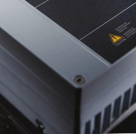
32 Commissioning VLT DriveMotor FCP 106/FCM B. Display menu key Menu keys are used for menu access for parameter set-up, toggling through status display modes during normal operation, and viewing fault log data. Callout Key Function 6 Status Shows operational information. 7 Quick Menu Allows access to programming parameters for initial set-up instructions and many detailed application instructions. 8 Main Menu Allows access to all programming parameters. 9 Alarm Log Shows a list of current warnings, Table 5.2 Legend to Illustration 5.2 the last 10 alarms, and the maintenance log. C. Navigation keys and indicator lights (LEDs) Navigation keys are used for programming functions and moving the display cursor. The navigation keys also provide speed control in local operation. There are also 3 frequency converter status indicator lights in this area. D. Operation keys and indicator lights (LEDs) Operation keys are at the bottom of the LCP. Callout Key Function 18 Hand On Starts the frequency converter in local control. An external stop signal by control input or serial communication overrides the local hand on. 19 Off Stops the motor but does not remove power to the frequency converter. 20 Auto On Puts the system in remote operational mode. Responds to an external start command by control terminals or serial communication. 21 Reset Resets the frequency converter manually Table 5.5 Legend to Illustration 5.2 NOTICE after a fault has been cleared. To adjust the display contrast, press [Status] and [ ]/[ ]. Callout Key Function 10 Back Reverts to the previous step or list in Connect LCP Cable the menu structure. 11 Cancel Cancels the last change or command as long as the display mode has not changed. 12 Info Press for a definition of the function 42 mm NA shown. 13 Navigation keys Press to move between items in the menu. 14 OK Press to access parameter groups or to enable a selection. Table 5.3 Legend to Illustration 5.2 Callout Indicator Light Function 15 ON Green The ON light activates when the frequency converter receives power from mains voltage, a DC bus terminal, or a 24 V external supply. 16 WARN Yellow When warning conditions are met, the yellow WARN light turns on, and text appears in the display area identifying the problem. 17 ALARM Red A fault condition causes the red alarm light to flash, and an alarm text is shown. Table 5.4 Legend to Illustration Control panel 2 Panel door Illustration 5.3 LCP Remote Mounting To view or change the frequency converter settings, attach the LCP using the LCP cable. See Illustration 5.3. After use, remove the LCP cable from the frequency converter to maintain the ingress protection class of the enclosure. 30 Danfoss A/S 11/2015 All rights reserved. MG03L302
33 Commissioning Operating Instructions 5.3 Memory Module MCM 101 The VLT Memory Module MCM 101 is a small memory plug containing data such as: Firmware. SIVP file. Pump table. Motor database. Parameter lists. The frequency converter comes with the module installed from the factory. 1 1 VLT Memory Module MCM 101 Illustration 5.4 Location of Memory Module If the memory module becomes defect, it does not prevent the frequency converter from working. The warning LED on the lid flashes, and a warning shows in the LCP (if installed). Warning 206, Memory module indicates that either a frequency converter runs without a memory module, or that the memory module is defect. To see the exact reason for the warning, refer to parameter Memory Module Warning Reason. A new memory module can be ordered as a spare part. Ordering number: 134B NA Configuring with the VLT Memory Module MCM 101 When replacing or adding a frequency converter to a system, it is easy to transfer existing data to the new frequency converter. However, the frequency converters must be of the same power size and with compatible hardware. WARNING DISCONNECT POWER BEFORE SERVICING! Before performing repair work, disconnect the frequency converter from AC mains. After mains has been disconnected, wait 4 minutes for the capacitors to discharge. Failure to follow these steps can result in death or serious injury. 1. Remove the lid from a frequency converter containing a memory module. 2. Unplug the memory module. 3. Place and tighten the lid. 4. Remove the lid from the new frequency converter. 5. Insert the memory module in the new/other frequency converter and leave it in. 6. Place and tighten the lid on the new frequency converter. 7. Power up the frequency converter. NOTICE The first power-up takes approximately 3 minutes. During this time, all data is transferred to the new frequency converter. 5.4 Basic Programming This manual explains initial set-up only. For full parameter lists, refer to the VLT DriveMotor FCP 106 and FCM 106 Programming Guide. At initial start-up, the frequency converter enters the startup wizard for open-loop applications, see chapter Configuration for Open-loop Applications. Once the start-up wizard has completed, the following extra set-up wizards and instructions are available: Chapter Set-up Wizard for Closed-loop Applications. Chapter Quick Menu Motor Set-up. Chapter Thermistor Set-up. For general instructions on how to change parameter settings, refer to chapter Changing Parameter Settings. 5 5 MG03L302 Danfoss A/S 11/2015 All rights reserved. 31
Installation Guide VLT PROFIBUS DP MCA 101
 MAKING MODERN LIVING POSSIBLE Installation Guide VLT PROFIBUS DP MCA 101 VLT Frequency Converter FC 102 FC 103 FC 202 FC 301/302 FCP 106 FCM 106 vlt-drives.danfoss.com Contents Installation Guide Contents
FLÄKTGROUP OFFERS A WIDE RANGE OF PER- MANENT MAGNET MOTORS (PM) AND FREQUENCY CONVERTERS FOR PLUG FANS. POWER RANGE IS FROM 0,8 KW TO 15 KW.
 AND FREQUENCY CONVERTERS FOR PLUG FANS. POWER RANGE IS FROM 0,8 KW TO 15 KW.") CENTRIFLOW PUR 3D (A, PLUG B, C, D) FAN GMPM FC101 AND SLIDE IN FREQUENCY ROTOR CASSETTE CONVERTER QUICK GUIDE FLÄKTGROUP OFFERS A WIDE RANGE OF PER- MANENT MAGNET MOTORS (PM) AND FREQUENCY CONVERTERS
CENTRIFLOW PUR 3D (A, PLUG B, C, D) FAN GMPM FC101 AND SLIDE IN FREQUENCY ROTOR CASSETTE CONVERTER QUICK GUIDE FLÄKTGROUP OFFERS A WIDE RANGE OF PER- MANENT MAGNET MOTORS (PM) AND FREQUENCY CONVERTERS
AF-600 FP TM Fan & Pump Drive. (230V to 60HP, 460/575V to 125HP Operating Instructions
 GE AF-600 FP TM Fan & Pump Drive (230V to 60HP, 460/575V to 125HP Operating Instructions Safety Safety WARNING HIGH VOLTAGE! Frequency converters contain high voltage when connected to AC mains input power.
Installation Guide VLT BACnet/IP MCA 125
 MAKING MODERN LIVING POSSIBLE Installation Guide BACnet/IP MCA 125 HVAC Drive FC 102 vlt-drives.danfoss.com Contents Installation Guide Contents 1 Introduction 2 1.1 Purpose of the Manual 2 1.2 Additional
User Guide VLT Parallel Drive Modules
 ENGINEERING TOMORROW User Guide VLT Parallel Drive Modules 250 1200 kw vlt-drives.danfoss.com Contents User Guide Contents 1 Introduction 4 1.1 Purpose of the Manual 4 1.2 Additional Resources 4 1.3 Manual
Installation Guide VLT EtherNet/IP MCA 121
 MAKING MODERN LIVING POSSIBLE Installation Guide VLT EtherNet/IP MCA 121 VLT HVAC Drive FC 102 VLT AQUA Drive FC 202 VLT AutomationDrive FC 301/302 www.danfoss.com/drives Contents Installation Guide Contents
FREQUENCY CONVERTER FC101 (QUICK GUIDE)
") FREQUENCY CONVERTER FC101 (QUICK GUIDE) INSTALLATION AND MAINTENANCE Content Page Safety instructions 2 IT system 3x230VAC 2 Connections 3 Control unit (LCP) 4 Manual operation 4 Reverse the direction
FREQUENCY CONVERTER FC101 (QUICK GUIDE) INSTALLATION AND MAINTENANCE Content Page Safety instructions 2 IT system 3x230VAC 2 Connections 3 Control unit (LCP) 4 Manual operation 4 Reverse the direction
Installation Guide VLT DeviceNet MCA 104
 MAKING MODERN LIVING POSSIBLE Installation Guide VLT DeviceNet MCA 104 VLT Frequency Converter Series FC 102 FC 202 FC 301 FC 302 vlt-drives.danfoss.com Contents Installation Guide Contents 1 Introduction
FREQUENCY CONVERTER FC102 (QUICK GUIDE)
") FREQUENCY CONVERTER FC102 (QUICK GUIDE) INSTALLATION AND MAINTENANCE Content Page Safety instructions 2 IT system 3x230VAC 2 Connections 3 Control unit (LCP) 4 Manual operation 4 Reverse the direction
FREQUENCY CONVERTER FC102 (QUICK GUIDE) INSTALLATION AND MAINTENANCE Content Page Safety instructions 2 IT system 3x230VAC 2 Connections 3 Control unit (LCP) 4 Manual operation 4 Reverse the direction
Installation Guide Modbus TCP Module
 ENGINEERING TOMORROW Installation Guide Modbus TCP Module VLT Compact Starter MCD 201/MCD 202 VLT Soft Starter MCD 500 vlt-drives.danfoss.com Contents Installation Guide Contents 1 Introduction 3 1.1
Operating instructions. Switching amplifier DN0210 DN / / 2015
 Operating instructions Switching amplifier DN0210 DN0220 UK 80011079 / 00 01 / 2015 Contents 1 Preliminary note...4 1.1 Symbols used...4 1.2 Warning signs used...4 2 Safety instructions...5 2.1 General...5
VLT Line Filter MCC 107 EMC Filter Series VLT Midi Drive FC 280 (K1 K3)
") These instructions provide technical and installation information for the MCC 107 EMC filter series. Only Danfoss qualified personnel is allowed to install this equipment. The personnel must be familiar
These instructions provide technical and installation information for the MCC 107 EMC filter series. Only Danfoss qualified personnel is allowed to install this equipment. The personnel must be familiar
Installation Guide EtherNet/IP Module
 ENGINEERING TOMORROW Installation Guide EtherNet/IP Module VLT Compact Starter MCD 201/MCD 202 VLT Soft Starter MCD 500 vlt-drives.danfoss.com Contents Installation Guide Contents 1 Introduction 3 1.1
Taco System Logic (TSL)
") Taco System Logic (TSL) 302-370 Installation, Operation, and Maintenance Manual SUPERSEDES: June 27, 2014 EFFECTIVE: December 21, 2015 Table of Contents 1 ELECTRICAL CONNECTIONS................. 2 1.1
Taco System Logic (TSL) 302-370 Installation, Operation, and Maintenance Manual SUPERSEDES: June 27, 2014 EFFECTIVE: December 21, 2015 Table of Contents 1 ELECTRICAL CONNECTIONS................. 2 1.1
Operating instructions. Speed monitor D / / 2014
 Operating instructions Speed monitor D200 80005257 / 00 05 / 2014 Contents 1 Preliminary note...4 1.1 Symbols used...4 1.2 Warning signs used...4 2 Safety instructions...5 2.1 General...5 2.2 Target group...5
REDUNDANCY MODULE TSP-REM360 AND TSP-REM600
 REDUNDANCY MODULE TSP-REM360 AND TSP-REM600 Operating Instructions Seite 1 Dimensions drawings: TSP-REM360 Weight: 0.882lb Gewicht: 0.40kg Seite 2 Dimensions drawings: TSP-REM600 Bottom view Top view Side
SMVector Additional I/O Module Installation and Operation Manual
 SMVector Additional I/O Module Installation and Operation Manual About These Instructions This documentation applies to the optional Additional I/O module for the SMVector inverter and should be used in
Rhino Buffer Module PSM24-BFM600S. Operating Instructions
 Rhino Buffer Module PSM24-BFM600S Operating Instructions RHINO BUFFER MODULE PSM24-BFM600S Description The PSM24-BFM600S Buffer Module will hold the output voltage of a 24 VDC power supply after brownouts
PowerLogic High Density Metering System 1-Meter Enclosure
 PowerLogic High Density Metering System 1-Meter Enclosure Installation Guide 63230-508-211A1 Safety information PowerLogic High Density Metering System 1-Meter Enclosure Important information Read these
Installation, Operation and Maintenance Manual
 Document 481200 VGD-100 Vari-Green Drive Installation, Operation and Maintenance Manual Please read and save these instructions for future reference. Read carefully before attempting to assemble, install,
QUICK START GUIDE. vau4/3. Frequency converter. operating instructions /12
 operating instructions QUICK START GUIDE Frequency converter vau4/3 28100241101 12/12 1 Safety information Warning of electrical shock! Danger to life! Electrical shock can cause serious injury or even
Installation Guide VLT Programmable I/O MCB 115
 MAKING MODERN LIVING POSSIBLE Installation Guide VLT Programmable I/O MCB 115 VLT AutomationDrive FC 302 vlt-drives.danfoss.com Contents Installation Guide Contents 1 Introduction 2 1.1 Purpose of the
User s Manual. ACS550-PD 3R Irrigation Packaged Drive Supplement to ACS550-U1 User s Manual
 User s Manual ACS550-PD 3R Irrigation Packaged Drive Supplement to ACS550-U1 User s Manual 2 ACS550-PD 3R Irrigation Packaged Drive ACS550 Drive Manuals GENERAL MANUALS ACS550-U1 User s Manual (1 200 HP)
Series Amp Pad Mount Quick Connect Input and Output Power Panels
 Series 300 2000-4000 Amp Pad Mount Quick Connect Input and Output Power Panels DANGER is used in this manual to warn of a hazard situation which, if not avoided, will result in death or serious injury.
HITACHI. EH-150 series PLC EH-RTD8 Resistance Temperature Detective input module Instruction manual. Safety precautions
 HITACHI EH-150 series PLC Resistance Temperature Detective input module Instruction manual Thank you for purchasing a Hitachi Programmable Logic Controller. To operate it safely, please read this instruction
RAD-DI8-IFS. I/O extension module with 8 digital inputs or 2 pulse inputs. INTERFACE Data sheet. 1 Description
 I/O extension module with 8 digital inputs or 2 pulse inputs INTERFACE Data sheet 0483_en_00 PHOENIX CONTACT 203-04-05 Description The I/O extension module can be used in conjunction with Radioline wireless
Vision OPLC V TR6/V350-J-TR6
 Vision OPLC V350-35-TR6/V350-J-TR6 Installation Guide The Unitronics V350-35-TR6/V350-J-TR6 offers the following onboard I/Os: 8 Digital Inputs, configurable via wiring to include 2 Analog (current/voltage)
Series Amp Quick Connect Input and Output Power Panels
 Series 300 1200-1600 Amp Quick Connect Input and Output Power Panels DANGER is used in this manual to warn of a hazard situation which, if not avoided, will result in death or serious injury. WARNING is
RAD-DO8-IFS. I/O extension module, eight digital transistor outputs. Data sheet. 1 Description
 I/O extension module, eight digital transistor outputs Data sheet 105364_en_00 PHOENIX CONTACT 2013-03-26 1 Description The I/O extension module can be used in conjunction with Radioline wireless modules
MDM 011-Z1 Regen Resistor
 MDM 011-Z1 Regen Resistor Date of creation: 10.04.2017 Version date: 10.04.2017 Article number: 09-402-011-Z1-E Publisher: SIGMATEK GmbH & Co KG A-5112 Lamprechtshausen Tel.: 06274/4321 Fax: 06274/4321-18
Siemens Industrial s
 SINAMICS G130 Operating Instructions 05/2010 SINAMICS Siemens Industrial s Sinusoidal filter Safety information 1 General 2 SINAMICS SINAMICS G130 Mechanical installation 3 Electrical installation 4 Technical
When any of the following symbols appear, read the associated information carefully. Symbol Meaning Description
 Vision OPLC V350-35-R34/V350-J-R34 Installation Guide The Unitronics V350-35-R34/V350-J-R34 offers the following onboard I/Os: 22 Digital Inputs, configurable via wiring to include 2 Analog and 3 HSC/Shaft-encoder
OPLC Installation Guide
 Samba OPLC SM35-J-R20/SM43-J-R20 SM70-J-R20 SM35-J-T20/SM43-J-T20 SM70-J-T20 OPLC Installation Guide 12 Digital Inputs, include 1 HSC/Shaft-encoder Input, 2 Analog inputs (only when the digital inputs
Rhino Redundancy Module PSM24-REM360S. Operating Instructions
 Rhino Redundancy Module PSM4-REM360S Operating Instructions RHINO REDUNDANCY MODULE PSM4-REM360S Description With this module and two power supplies of the PSM series (78, 90, 56, 80 and 360 watt models),
Operating Guide VLT HVAC Drive FC 102
 ENGINEERING TOMORROW Operating Guide VLT HVAC Drive FC 102 355 800 kw, Enclosure Size E vlt-drives.danfoss.com Contents Operating Guide Contents 1 Introduction 3 1.1 Purpose of the Manual 3 1.2 Additional
RAD-DOR4-IFS. I/O extension module, 4 digital relay outputs. INTERFACE Data sheet. 1 Description
 I/O extension module, 4 digital relay outputs INTERFACE Data sheet 104834_en_01 PHOENIX CONTACT 2013-01-21 1 Description The RAD-DOR4-IFS I/O extension module can be used in conjunction with Radioline
1 How to Read these Operating Instructions 3. 3 Introduction to MCF 106 A/ B in C Option Adaptor 7
 MCF 106 A/ in C Option Adaptor Instruction Contents Contents 1 How to Read these Operating Instructions 3 Available Literature for VLT AutomationDrive FC 300 3 Approvals 4 Symbols 4 Abbreviations 4 2 Safety
SMVector Additional I/O Module Installation and Operation Manual
 SMVector Additional I/O Module Installation and Operation Manual About These Instructions This documentation applies to the optional Additional I/O module for the SMVector inverter and should be used in
Chameleon Stand-alone
 Quick Installation Guide Installation and Commissioning Chameleon Stand-alone Power Supply Module, 48 VDC, 650W, HE, IP65 Low Power Outdoor Applications 356849.03 Introduction Warnings..., page 3 Tools
Operating Guide VLT AutomationDrive FC 302
 ENGINEERING TOMORROW Operating Guide VLT AutomationDrive FC 302 315 710 kw, Enclosure Size E vlt-drives.danfoss.com Contents Operating Guide Contents 1 Introduction 3 1.1 Purpose of the Manual 3 1.2 Additional
Resolver to Digital Expansion Board
 Resolver to Digital Expansion Board Catalog No. EXB009A01 Installation and Operating Manual 6/98 MN1313 Table of Contents Section 1 General Information............................. 1-1 Introduction....................................
ATS22D75S6U. Main. Range of product Altistart 22. Component name. Factory setting current. Utilisation category. IP degree of protection
 Product datasheet Characteristics ATS22D75S6U Complementary Assembly style Function available Supply voltage limits Main Range of product Altistart 22 Product or component type Product destination Product
TRIO-DIODE/12-24DC/2X10/1X20
 Redundancy module INTERFACE Data sheet 104278_en_00 1 Description PHOENIX CONTACT 20100423 Features TRIO DIODE is the DINrail mountable redundancy module from the TRIO POWER product range. Using the redundancy
Operating Guide VLT HVAC Drive FC 102
 ENGINEERING TOMORROW Operating Guide VLT HVAC Drive FC 102 355 800 kw, Enclosure Sizes E1h E4h www.danfossdrives.com Contents Operating Guide Contents 1 Introduction 4 1.1 Purpose of the Manual 4 1.2
Analog Monitor Installation Manual
 Analog Monitor Installation Manual Part Number: 144-23919 Copyright 2011 Magnetek 1. Preface and Safety Magnetek manufactures products used as components in a wide variety of industrial systems and equipment.
MINI-PS AC/10-15DC/8
 Primary-Switched Power Supply, Narrow Design Data Sheet 08/2004 MINI POWER provides: An extra narrow design, with widths of 22.5 mm, 45 mm, and 67.5 mm (0.886, 1.772, and 2.657 in.) Global use due to a
dv/dt filter compact plus Voltage Peak Limiter SINAMICS SINAMICS G120P dv/dt filter compact plus Voltage Peak Limiter Safety information 1 General 2
 dv/dt filter compact plus Voltage Peak Limiter SINAMICS SINAMICS G120P dv/dt filter compact plus Voltage Peak Limiter Operating Instructions Safety information 1 General 2 Mechanical installation 3 Electrical
The identified danger could cause physical and property damage.
 Samba OPLC SM35-J-T20 Installation Guide The Unitronics SM35-J-T20 offers the following onboard I/Os: 12 Digital Inputs, configurable via wiring to include 2 Analog and 3 HSC/Shaft-encoder Inputs 8 Transistor
When any of the following symbols appear, read the associated information carefully. Symbol Meaning Description
 Uni-I/O Wide Modules Installation Guide UID-W1616R, UID-W1616T Uni-I/O Wide is a family of Input/Output modules that are compatible with the UniStream control platform. Wide Modules are 1.5 times as wide
Installation Instructions
 50ES, 50EZ, 50GL, 50GS, 50GX, 50JS, 50JX, 50JZ, 50SD, 50SZ, 50VL, 50VT, 50XP, 50XZ 601A, 602A, 602B, 604A, 604B, 604D, 607C, 701A, 702A, 702B, 704A, 704B, 704D, 707C PA1P, PA2P, PA3P, PH1P, PH2P, PH3P
PanelView Plus/VersaView CE Terminals and Display Modules
 Installation Instructions PanelView Plus/VersaView CE Terminals and Display Modules (Catalog Numbers 2711P-xxxxxx, 6182H-xxxxxx) English Inside: Overview...2 For More Information...2 Modular Components...3
Operating instructions. Standstill monitor A / / 2011
 Operating instructions Standstill monitor A300 UK 1 2 3 4 5 6 7 8 7390337 / 01 02 / 2011 1 2 3 4 5 6 7 8 switchpoint min max pulse/min power Made in Germany ifm electronic gmbh D 45127 Essen func. I II
PTC/PT100 board 2.0 Option
 PTC/PT100 board 2.0 Option Instruction Manual - English PTC/PT100 board 2.0 Option Instruction Manual - English Document number: 01-3873-01 Edition: r1 Date of release: 2006-10-30 Copyright Emotron AB
22 Digital Inputs, including 2 Analog, 2 HSC/Shaft-encoder inputs 16 Transistor Outputs
 Vision PLC+HMI V130-33-T38/V130-J-T38 V350-35-T38/V350-J-T38 V430-J-T38 Installation Guide 22 Digital Inputs, including 2 Analog, 2 HSC/Shaft-encoder inputs 16 Transistor Outputs General Description All
Operating instructions AS-i SmartLine module AC3200 AC /00 06/2016
 Operating instructions AS-i SmartLine module AC3200 AC3201 80237876/00 06/2016 Contents 1 Preliminary note...3 1.1 Symbols used...3 1.2 Warnings used...3 2 Safety instructions...3 2.1 General...3 2.2 Target
GV3000/SE Operator Interface Module (OIM) User Guide Version 2.0 M/N 2RK3000
 User Guide Version 2.0 M/N 2RK3000") GV3000/SE Operator Interface Module (OIM) User Guide Version 2.0 M/N 2RK3000 Instruction Manual D2-3342-2 The information in this manual is subject to change without notice. Throughout this manual, the
GV3000/SE Operator Interface Module (OIM) User Guide Version 2.0 M/N 2RK3000 Instruction Manual D2-3342-2 The information in this manual is subject to change without notice. Throughout this manual, the
ATS22D47S6U. Main. Range of product Altistart 22. Component name. Factory setting current. Utilisation category. IP degree of protection
 Product datasheet Characteristics ATS22D47S6U Complementary Assembly style Function available Supply voltage limits Main Range of product Altistart 22 Product or component type Product destination Product
PHOENIX CONTACT - 08/2009. Features. DANGER OF EXPLOSION! Only remove equipment when it is disconnected and not in the potentially explosive area.
 Primary-switched power supply for building automation INTERFACE Data sheet 103505_en_02 1 Description PHOENIX CONTACT - 08/2009 Features STEP POWER power supply units for building automation The new STEP
ATS22C17Q. Main. Range of product Altistart 22. Component name. Factory setting current. Utilisation category. IP degree of protection
 Product datasheet Characteristics ATS22C17Q Complementary Assembly style Function available Supply voltage limits Main Range of product Altistart 22 Product or component type Product destination Product
EPS 06 in rear housing type A1
 Field Installation and / or Replacement of RACO Electronic Position Sensor Board EPS 02 & EPS 06 - Electronic Limit Switches - Analog Output Position Signal - Very Accurate - Easy To Use - Robust - Dependable
Electromotoric actuators Torques up to 60 Nm Running times ¹) s. ¹) Predefined by the basic unit (LMV5...)
 s. ¹) Predefined by the basic unit (LMV5...)") 7 818 Actuators SQM9... Electromotoric actuators Torques up to 60 Nm Running times ¹) 30...120 s ¹) Predefined by the basic unit (LMV5...) The SQM9... and this Data Sheet are intended for use by OEMs which
7 818 Actuators SQM9... Electromotoric actuators Torques up to 60 Nm Running times ¹) 30...120 s ¹) Predefined by the basic unit (LMV5...) The SQM9... and this Data Sheet are intended for use by OEMs which
GV3000/SE AC Drive ControlNet Network Communication Option Board M/N 2CN3000
 GV3000/SE AC Drive ControlNet Network Communication Option Board M/N 2CN3000 Instruction Manual D2-3390-2 The information in this manual is subject to change without notice. Throughout this manual, the
Digital ac/dc (24V) Input Module
 Input Module") Installation Instructions Digital ac/dc (24V) Input Module Catalog Number 1771-IND, Series C Topic Page Important User Information 2 Before You Begin 3 Power Requirements 3 Prevent Electrostatic Discharge
Installation Instructions Digital ac/dc (24V) Input Module Catalog Number 1771-IND, Series C Topic Page Important User Information 2 Before You Begin 3 Power Requirements 3 Prevent Electrostatic Discharge
Power Supply. Users Guide PRODUCT MANUAL. WESTELL.COM Westell Technologies MNL rd
 PRODUCT MANUAL Power Supply Westell Technologies. 960-1152-MNL rd DISCLAIMER All information and statements contained herein are accurate to the best of Westell Technologies knowledge. Westell Technologies
WARNING ELECTRICAL SHOCK HAZARD
 Description Safety Instructions The top-entry sub D9 connector kit is designed for enclosure sizes D1h D8h, E1 E2, and E1h E4h with VLT PROFIBUS DP MCA 101 option. It fits the following drives: VLT HVAC
ATS22D88S6U. ATS22D88S6U soft starter-ats22-control110v-power 208V(25hp)/230V(30hp)/460V(60hp)/575V(75hp) Product data sheet Characteristics.
/230V(30hp)/460V(60hp)/575V(75hp) Product data sheet Characteristics.") Characteristics soft starter-ats22-control110v-power 208V(25hp)/230V(30hp)/460V(60hp)/575V(75hp) Main Range of product Altistart 22 Product or component type Product destination Product specific application
Characteristics soft starter-ats22-control110v-power 208V(25hp)/230V(30hp)/460V(60hp)/575V(75hp) Main Range of product Altistart 22 Product or component type Product destination Product specific application
When any of the following symbols appear, read the associated information carefully. Symbol Meaning Description
 Uni-I/O Modules Installation Guide UID-0808THS Uni-I/O is a family of Input/Output modules that are compatible with the UniStream control platform. This guide provides basic installation information for
QUINT-BUFFER/24DC/24DC/40
 Buffer module Data sheet 105496_en_01 PHOENIX CONTACT 2013-11-01 1 Description The QUINT BUFFER buffer module combines the electronic switchover unit and power storage in the same housing. The buffer module
INSTRUCTION MANUAL. IM255 Rev C. Aquavar Intelligent Pump Controller
 INSTRUCTION MANUAL IM255 Rev C Aquavar Intelligent Pump Controller Table of Contents Table of Contents 1 Introduction and Safety...3 1.1 Introduction... 3 1.1.1 Qualified personnel...3 1.2 Safety... 3
1 Extended and Advanced Cascade Controller Option 3
 VLT Operating Instructions Contents Contents Extended and Advanced Cascade Controller 3 How to read these Operating Instructions 3 High Voltage Warning 3 Safety Instructions 3 Avoid unintended Start 3
ATS22C11S6U soft starter-ats22-control110vpower208v(30hp)/230v(40hp)/460v(75hp)/575v(100h
/230v(40hp)/460v(75hp)/575v(100h") Characteristics soft starter-ats22-control110vpower208v(30hp)/230v(40hp)/460v(75hp)/575v(100h Complementary Assembly style Function available Power supply voltage limits Main Range of product Altistart
Characteristics soft starter-ats22-control110vpower208v(30hp)/230v(40hp)/460v(75hp)/575v(100h Complementary Assembly style Function available Power supply voltage limits Main Range of product Altistart
Line reactors SINAMICS. SINAMICS G130 Line reactors. Safety information 1. General. Mechanical installation 3. Electrical installation
 Safety information 1 General 2 SINAMICS SINAMICS G130 Mechanical installation 3 Electrical installation 4 Technical specifications 5 Operating Instructions Control version V4.7 04/2014 A5E00331462A Legal
ATS22D62Q soft starter-ats22-control 220V-power 230V(15kW)/ V(30kW)
/ V(30kW)") Characteristics soft starter-ats22-control 220V-power 230V(15kW)/400...440V(30kW) Main Range of product Altistart 22 Product or component type Product destination Product specific application Component
Characteristics soft starter-ats22-control 220V-power 230V(15kW)/400...440V(30kW) Main Range of product Altistart 22 Product or component type Product destination Product specific application Component
OPERATING INSTRUCTIONS 7 SERIES STATIC GENERATORS
 OPERATING INSTRUCTIONS 7 SERIES STATIC GENERATORS GB Contents Page 1 Introduction 4 2 Safety 5 3 Use 6 4 Checking on Delivered Equipment 6 5 General Specification and Dimensions 7 6 Positioning 10 7 Operating
ATS22D17Q soft starter-ats22-control 220V-power 230V (4kW)/ V(7.5kW)
/ V(7.5kW)") Product datasheet Characteristics ATS22D17Q soft starter-ats22-control 220V-power 230V (4kW)/400...440V(7.5kW) Complementary Assembly style Function available Supply voltage limits Main Range of product
Product datasheet Characteristics ATS22D17Q soft starter-ats22-control 220V-power 230V (4kW)/400...440V(7.5kW) Complementary Assembly style Function available Supply voltage limits Main Range of product
ATS22C21S6U softstarter-ats22-control110vpower208v(60hp)/230v(75hp)/460v(150hp)/575v(200hp)
/230v(75hp)/460v(150hp)/575v(200hp)") Characteristics softstarter-ats22-control110vpower208v(60hp)/230v(75hp)/460v(150hp)/575v(200hp) Main Range of product Altistart 22 Product or component type Product destination Product specific application
Characteristics softstarter-ats22-control110vpower208v(60hp)/230v(75hp)/460v(150hp)/575v(200hp) Main Range of product Altistart 22 Product or component type Product destination Product specific application
User Manual. Solar Inverter for Water Pump
 User Manual Solar Inverter for Water Pump SP Revival Series Version: 1.2 Table Of Contents ABOUT THIS MANUAL... 1 Purpose... 1 Scope... 1 SAFETY INSTRUCTIONS... 1 Inspection... 1 Installation... 1 Operation...
Installation Guide PROFINET Module
 ENGINEERING TOMORROW Installation Guide PROFINET Module VLT Compact Starter MCD 201/MCD 202 VLT Soft Starter MCD 500 vlt-drives.danfoss.com Contents Installation Guide Contents 1 Introduction 3 1.1 Purpose
TPE, TPED Series 2000
 GRUNDFOS INSTRUCTIONS TPE, TPED Series 2000 Installation and operating instructions English (GB) English (GB) Installation and operating instructions Original installation and operating instructions. CONTENTS
SITOP power supply. Selectivity modules. Overview. Safety notes. Description, device design, dimension drawing. Mounting/removal 3
 Overview Safety notes 1 SITOP power supply Manual Description, device design, dimension drawing 2 Mounting/removal 3 Mounting position, mounting clearances 4 Installation 5 Technical data 6 Safety, approvals,
ATV930U30M3 variable speed drive - ATV930-3kW - 200/240Vwith braking unit - IP21
 Characteristics variable speed drive - ATV930-3kW - 200/240Vwith braking unit - IP21 Main Range of product Product or component type Device application Device short name Variant Product destination Mounting
ATS22D75Q soft starter-ats22-control 220V-power 230V(18.5kW)/ V(37kW)
/ V(37kW)") Product data sheet Characteristics ATS22D75Q soft starter-ats22-control 220V-power 230V(18.5kW)/400...440V(37kW) Complementary Assembly style Function available Power supply voltage limits Main Range of
Product data sheet Characteristics ATS22D75Q soft starter-ats22-control 220V-power 230V(18.5kW)/400...440V(37kW) Complementary Assembly style Function available Power supply voltage limits Main Range of
5401 and 5402 Digital I/O Modules
 50 and 50 Digital I/O Modules Installation, Operation and Maintenance Setup Manual 5/9/0 Safety Information The information provided in this documentation contains general descriptions and/or technical
ATS22C41Q soft starter-ats22-control 220V-power 230V(110kW)/ V(220kW)
/ V(220kW)") Characteristics soft starter-ats22-control 220V-power 230V(110kW)/400...440V(220kW) Complementary Assembly style Function available Power supply voltage limits Main Range of product Altistart 22 Product
Characteristics soft starter-ats22-control 220V-power 230V(110kW)/400...440V(220kW) Complementary Assembly style Function available Power supply voltage limits Main Range of product Altistart 22 Product
SINAMICS. SINAMICS G120P dv/dt filter plus Voltage Peak Limiter. Safety information 1. General. Mechanical installation. Electrical installation 4
 Safety information 1 General 2 SINAMICS SINAMICS G120P dv/dt filter plus Voltage Peak Limiter Operating Instructions Mechanical installation 3 Electrical installation 4 Maintenance and servicing 5 Technical
Symmetra PX 160. Maintenance Bypass Enclosure. Installation 05/
 Symmetra PX 160 Maintenance Bypass Enclosure Installation 05/2014 www.schneider-electric.com Legal Information The Schneider Electric brand and any registered trademarks of Schneider Electric Industries
STEP-PS/1AC/24DC/1.75
 Primary-switched power supply, 1 AC, output current 1.75 A INTERFACE Data Sheet 103506_en_00 1 Description PHOENIX CONTACT - 05/2008 Features STEP POWER power supply units for building automation The new
ATS22D75S6 soft starter-ats22-control 220V-power 230V(18.5kW)/ V(37kW)/500V(45kW)
/ V(37kW)/500V(45kW)") Characteristics soft starter-ats22-control 220V-power 230V(18.5kW)/400...440V(37kW)/500V(45kW) Price* : 683.00 GBP Main Range of product Altistart 22 Product or component type Product destination Product
Characteristics soft starter-ats22-control 220V-power 230V(18.5kW)/400...440V(37kW)/500V(45kW) Price* : 683.00 GBP Main Range of product Altistart 22 Product or component type Product destination Product
Operating and Installation Manual. EASYLAB Expansion modules Type EM-TRF for 230 V AC mains voltage
 Operating and Installation Manual EASYLAB Expansion modules Type EM-TRF for 230 V AC mains voltage Type EM-TRF-USV for 230 V AC mains voltage; provides uninterruptible power supply (UPS) The art of handling
Removal and Installation8
 8 Screw Types 8-4 Top Cover Assembly 8-5 Left Hand Cover 8-6 Right Hand Cover 8-10 Front Panel Assembly 8-14 Left Rear Cover 8-15 Right Rear Cover 8-16 Extension Cover (60" Model only) 8-17 Media Lever
Tempco Instruction Manual
 Tempco Instruction Manual 1/16 DIN Solid State Temperature Controller Relay Output Solid State Output For Heating Model Numbers: TEC-901, TEC-902, TEC-905 Temperature controls in this series are designed
Line filter SINAMICS. SINAMICS G130 Line filter. Safety information 1. General 2. Mechanical installation 3. Electrical installation 4
 Safety information 1 General 2 SINAMICS SINAMICS G130 Mechanical installation 3 Electrical installation 4 Technical specifications 5 Operating Instructions Control version V4.8 07/2016 A5E00331460A Legal
50% VLT HVAC Basic Drive a compact and competitive solution for applications with basic needs. energy costs savings
 MAKING MODERN LIVING POSSIBLE VLT HVAC Basic Drive a compact and competitive solution for applications with basic needs 50% energy costs savings Typically, a 20% reduction in speed will yield 50% energy
Line reactors SINAMICS. SINAMICS G120P Line reactors. Safety information 1. General. Mechanical installation 3. Electrical installation 4
 Safety information 1 General 2 SINAMICS SINAMICS G120P Mechanical installation 3 Electrical installation 4 Technical specifications 5 Operating Instructions Control version V4.6 11/2013 A5E32845290B AA
ControlKeeper 4. General Information. Connecting Relay Loads. Installation Sheet. Getting Started. Power Supply Wiring. Mounting the Cabinet
 General Information ControlKeeper 4 Installation Sheet Model# CK4-120NO- Model# CK4-277NO The ControlKeeper-4 model is shipped in one package and is configured with either a 120V or a 277V transformer.
Operating Instructions (Translation) 3. Safety Information. 1. Description. 2. Explosion Protection. Supply module Type 17-21BB-170x
 3. Safety Information. 1. Description. 2. Explosion Protection. Supply module Type 17-21BB-170x") 1. Description The supply module was developed specially for direct mounting in hazardous areas in Zone 1 and 21 and is ATEX-certified. The supply module is a permanently installed piece of electrical
1. Description The supply module was developed specially for direct mounting in hazardous areas in Zone 1 and 21 and is ATEX-certified. The supply module is a permanently installed piece of electrical
Operating Instructions
 TPS S1 AC in DC out Translation of the original instructions TPS 110-400 Mains pack Operating Instructions PT 0199 BEN/C (1010) EN Table of contents Table of contents 1 About this manual...............................................
When any of the following symbols appear, read the associated information carefully. Symbol Meaning Description
 Uni-I/O Modules Installation Guide UID-0808R, UID-0808T, UID-1600,UID-0016R, UID-0016T Uni-I/O is a family of Input/Output modules that are compatible with the UniStream control platform. This guide provides
User Manual HMI Linkbox HL01 DP/MPI
 User Manual HMI Linkbox HL01 DP/MPI Part Number: 80860.603 Version: 1 Date: 07.05.2005 Valid for: HL01 DP/MPI Version Date Modifications 1 07.05.2005 First edition This manual, including all illustrations
H Series PLC. ! : Indicates Compulsion. EH-150 Analog input module EH-AXH8M Instruction manual. Safety precautions DANGER CAUTION COMPULSION
 H Series PLC EH-150 Analog input module EH-AXH8M Instruction manual Thank you for purchasing a Hitachi Programmable Logic Controller. To operate it safely, please read this instruction manual and all the