ZENSOL CIRCUIT BREAKER PERFORMANCE ANALYZER
|
|
|
- Thomas Freeman
- 5 years ago
- Views:
Transcription
1 COMPUTERIZED TEST INSTRUMENTS ZENSOL CIRCUIT BREAKER PERFORMANCE ANALYZER CBA-32P QUICK SETUP GUIDE August 5th,
2 CONTENTS CONTENTS... 2 STEP 1 REQUIRED MATERIALS... 3 STEP 1A ACCESSORIES... 4 STEP 2 CONNECTIONS... 8 STEP 2A CBA 32P CHANNELS CONFIGURATION... 8 STEP 2B CONNECTIONS TO THE BREAKER... 9 STEP 3 SOFTWARE INSTALLATION AND FOLDER STRUCTURE...10 STEP 3A DOWNLOADING THE APPLICATION FROM THE ZENSOL WEBSITE STEP 3B DECOMPRESSING AND INSTALLING ON WINDOWS XP (METHOD 1): STEP 3C DECOMPRESSING AND INSTALLING ON WINDOWS XP (METHOD 2): STEP 3D DECOMPRESSING AND INSTALLING ON WINDOWS VISTA / STEP 3E FOLDER STRUCTURE STEP 3F INSTALLING THE WINDOWS UPDATE FOR HELP FILES STEP 4 COMMUNICATION (USB DRIVER OR FIBER OPTIC INSTALLATION)...16 STEP 5 STARTING WITH THE SOFTWARE...17 STEP 5A LANGUAGE CONFIGURATION STEP 5B MAIN WINDOW STEP 5C DATA STRUCTURE...21 STEP 5D CALIBRATION CHECKUP STEP 5E TESTING THE COMMUNICATION STEP 5F TEST CABLES / BREAKERS STATUS STEP 5G CREATING/LOADING A NEW TEST PLAN STEP 5H ANALOG INPUTS CONFIGURATION STEP 5I EXECUTING A TEST STEP 5J SAVING THE TESTS STEP 6 TEST PLAN EXAMPLE: CHECK_CBA.WCF...28 APPENDIX 1 SYMBOLIC CIRCUIT DIAGRAM...31 APPENDIX 2 COMMUNICATION TESTS...32 APPENDIX 3 STATIC AND DYNAMIC RESISTANCE KIT


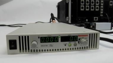
3 STEP 1 REQUIRED MATERIALS CBA 32P Power cable Ground cable Fiber optics module and cable ARCTIC / Standards contact cables Command cable 3


4 Step 1a Accessories Displacement transducers: Linear Rotary Optic encoder Voltage transducers: ZVD AC/DC 300 Contact ZVS DC 08 ZVD AC/DC 300 Contact (Wet Contact): detects alternative or continuous voltage. This item is excellent for a fast detection of possible malfunctions on control cabinets. ZVS DC 08: measures voltages inside a breaker control cabinet. Continuous voltage can reach 300 Volts. 4


5 Current transducers: ZCS 100 ZCS 600 ZCS 100 : Measures AC, DC or pulsed currents. This item is ideal for current measures in your breaker wires. Accept current up to 100A. ZCS 600 : Measures AC, DC or pulsed currents. This item is ideal for current measures in your breaker wires. Accept current up to 600A Static and dynamic micro ohmmeter kit: MO SD 100 / MO SD 200 This module is a diagnostic tool that assesses the state of circuit breaker contacts by measuring their dynamic arcing contact. 5


6 First trip monitoring : This module is designed to evaluate the breaker contacts opening time when «online». Internal resistance measurement module: Z FT RES 8 / RES 16 / RES 24 6


7 Digital inputs for optic encoders: Internal modules DIG INP 3 and DIG INP 6 were mainly created to measure the displacement of breaker contacts. DIG INP Weet contact module: WET CONT It detects continuous voltage: this module is highly efficient for a fast detection of any possible breaker malfunctions. 7
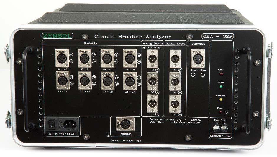
8 STEP 2 CONNECTIONS Step 2a CBA 32P Channels configuration Digital Contacts 17: first contact 18: second contact 40: twenty fourth contact PHYSICAL SIGNALS VIRTUAL SIGNALS Multiple Use Analog Inputs 3: first displacement 9: speed related to first displacement 4: displacement 10: speed related to second displacement 8: sixth displacement 14: speed related to sixth displacement Optical Encoders 89: first optical encoder 95: speed related to first encoder 90: second optical encoder 96: speed related to second encoder 94: sixth optical encoder 100: speed related to sixth encoder Command 1: close current input 2: open current input 61: close command 62: open command 8

9 Step 2b Connections to the breaker 9


10 STEP 3 SOFTWARE INSTALLATION AND FOLDER STRUCTURE Step 3a Downloading the application from the Zensol website Go to and in the products menu, select CBA 32P Circuit Breaker Analyzer. In the product page of the CBA 32P, scroll down to the CUSTOMERS section and click on the "CBAWin Software" link. Enter your username and password when prompted. Save the ZIP file on your computer at the location of your choice. 10
: CBAWin.")
11 Step 3b Decompressing and installing on Windows XP (method 1): Right click on the icon for the file you just downloaded: Select "Extract to " (note: this example uses WinZip other extractors may vary in their method): CBAWin.zip (or file for latest version and date) Select the folder of your choice, and before proceeding, make sure that the option "Use folder names" is selected: A new folder will appear at the location specified in the previous step (example folder name): CBAWin 11

12 Step 3c Decompressing and installing on Windows XP (method 2): Use this method in case the one in Step 2b fails or cannot be executed. Double click on the icon for the file you just downloaded: CBAWin.zip (or file for latest version and date) Click the "Extract" button (note: this example uses WinZip other extractors may vary in their method): Select the folder of your choice, and before proceeding, make sure that the option "Use folder names" is selected: A new folder will appear at the location specified in the previous step (example folder name): CBAWin 12
: CBAWin Enter")

13 Step 3d Decompressing and installing on Windows Vista / 7 Right click on the icon for the file you just downloaded (exact file name will depend on version downloaded): CBAWin Enter the destination folder where you want the files decompressed (click on Browse to search for a suitable folder example folder name shown or type in an absolute path, such as C:\CBAWin ): 13

14 Step 3e Folder structure Contents of the CBA Win folders: Autodiag Test and example to do an autodiagnostic of your analyser. Calibration Calibration files used by the software. Examples Examples of test plans and data files. Help Help files Plans_normalisés_HQ Standard test plan by Hydro Québec. Plugins Plugin which allows to export data in XML USB USB driver (optional) WinHlp Update Windows VISTA and 7 updates for help files (optional). 14
15 Step 3f Installing the windows update for help files This section is only for Windows Vista or Windows 7 users Double click on WinHlp Update folder, then on the file : VISTA KB x86 for Windows Vista users, OR Windows7 KB x86 for Windows 7 users. Follow the instructions displayed on the screen. Once the update is installed, you can open the help file. 15
 Plug the fiber optic cable connectors")


16 STEP 4 COMMUNICATION (USB driver or fiber optic installation) Plug the fiber optic cable connectors into their respective receptacles on the front panel of the CBA unit. Connect the other end to the receptacles on the fiber optic module. Connect the power cable between the CBA and the wall socket. Turn on the unit using the power switch on the front panel. Connect the serial cable from the fiber optic module to a free serial port on your computer. If your computer doesn t have a serial port, we offer a Serial to USB converter: 16

17 STEP 5 STARTING WITH THE SOFTWARE Double click on file cbawinxxx.exe, where XXX is the version number. We recommend that you create a desktop shortcut to this file to simplify access. Right Click Send To Desktop (create shortcut) Under Windows Vista, you must start the application using administrator rights ; right click cbawinxxx.exe Run as administrator 17


18 Step 5a Language configuration If you wish to change the language under CBA Win : Go to File Preferences Language and in the dialog window, select the language of your choice 18
19 Step 5b Main window Signals information Toolbar Number and Name of the Test. Number and Name of the Page. File name. Recorded data Calculus related to data Date and time of the current test Information about the plan and current test 19
20 Toolbar : Files Manipulation Test configuration In the field Analysis Assistant mode Test configuration Check setup Previous page Open plan Plan information Test link Next page Save data Analog inputs Test cables/breaker status Examine Export Contacts Close Order Horizontal scalel EVA export Optical encoders Open Order Vertical scale Print displayed report Processing Connections / Infos Zoom Previous test Next test Execute test Static/Dynamic Micro Ohmmeter Graphic report design Viewr tabular report Help 20


21 Step 5c Data structure Tous les signaux Fichier : DEFAULT_CHECK_CBA.wdt EXCEL Report.xls TEST PLAN DEFAULT_CHECK_CBA.wcf TABULAR TXTREP652.rep RAW DATA DEFAULT_CHECK_CBA.wdt CALCULUS CBACAL86.cal 21


22 Step 5d Calibration checkup Once the Verification button is pressed, the software connects to your instrument, reads the calibration data and applies it to your test plan. It will also indicate you if the test plan is compatible with your instrument. It has to be done every time you open a new blank test plan. Step 5e Testing the communication Set the communication port : Go to File Preferences Communication and then click on the which port is used. button to auto detect 22

23 Step 5f Test cables / breakers status Check if the connectors are responding. Check the connection between the CBA unit and the breaker contacts via cables. Check the position of linear and rotary transducers. Ideally the rotary transducer should be near 50%. Check the optical encoders position. 23


24 Step 5g Creating/Loading a new test plan To load a test plan: 1st method: File > Open Plan 2nd method: 3rd method: If you want to create a new test plan, change the configuration of the tests with the first green button. 24


25 Step 5h Analog inputs configuration When you open a test plan, it probably has default analog values. Once you have verified the calibration in the previous step, you can scale this calibration to the real values you measure. A good habit to have is to save the test plan once your calibration data is entered, so that you won t have to do it twice. In the properties of the current analog input, you can change the current range for a better measure of the current coils. In the properties of the other analog input, you can change the calibration values of the transducer you are using and put the measurement units. In the following picture, it is the example of a displacement transducer. 25

26 Step 5i Executing a test To run the current test, click on the button. A warning message will be displayed prior to the actual execution of the test. Once the test is completed, a progress bar is displayed indicating the proportion of data received from the analyzer. Once the data transfer is complete, the graphic display is immediately updated with the new data. Note: To add an audible warning ( buzzer ) before the execution of the test, go to File Preferences Test execution delay Activate 26
.")
27 Step 5j Saving the tests To save your data once your tests are complete, click on. You may also access this via the File Save data as Tip: After each test, save the current test (keeping the same file name). Thus you are sure to not lose your data in case of an unexpected problem. 27

28 STEP 6 TEST PLAN EXAMPLE: CHECK_CBA.WCF Test 1: Contact inputs This test involves testing all contact inputs in order to verify that they can detect a short circuit (closed) condition. To do this: Connect all the contact cables to the CBA 32P; For each contact cable, short the clips together, as seen at right in order to simulate closed contacts; In CBA Win, load the test plan AUTODIAG.WCF Execute the Test 1, Page 1 Use the Examine tool to verify that all the contacts are at level "1" 28
; A white clip (signal); A red clip (10 VDC); For each analog cable, short the red clip (identified 10 VDC) to the white clip (identified SIGNAL) as")
29 Test 2: Analog inputs This test involves testing all the analog inputs in order to verify that they can properly measure the voltage. To do this: Plug in all the analog displacement cables. These cables have: o o o A black clip (ground); A white clip (signal); A red clip (10 VDC); For each analog cable, short the red clip (identified 10 VDC) to the white clip (identified SIGNAL) as illustrated at right. This injects 10 volts DC into the analog signal input; Execute the Test 2, Page 2 with the test plan AUTODIAG.WCF Use the Examine tool to verify that all the analog inputs are at or close to 10 volts, ±5% the values are shown at the left of the graphic; 29

30 Test 3: Dynamic test of Contact inputs 1 2 and the Contactors This test involves dynamically testing contact inputs 1 2 (digital channels 17 and 18) and the internal contactors. The internal contactors are relays that behave like circuit breaker contacts and may be used to dynamically test the contact inputs. To do this: Plug the command cable into the CBA 32P; Plug a contact cable into the first contact input jack (17 18); Connect the two cables together as shown at right: o the white clip of the command cable to the red clip of the contact cable; o the black clip of the command cable to the yellow clip of the contact cable; o the red and green clips of the command cable to the black clip of the contact cable; Execute the Test 5, Page 5 with the test plan AUTODIAG.WCF The contact signals and the current signals should be similar in shape and timing; You can do the same test for any other contacts by moving the contact cable to the next contact inputs. If any of the tests show you an anomaly, contact ZENSOL for assistance. 30


31 APPENDIX 1 SYMBOLIC CIRCUIT DIAGRAM COMMUNICATION MODULE 31
 If it does not work, go to File > Preferences")

32 APPENDIX 2 COMMUNICATION TESTS Before executing a test, check the communication link with the following button: 1) If it does not work, go to File > Preferences > Communication, and check the port number with the goggles. The port COM should be highlighted with a green point. Check the COM port and try again the test link. 32
 Go to the Windows Configuration Panel, then System,")

33 2) If it still does not work, you can verify manually what the assigned COM port is. (Works with Windows XP, Vista, 7 and 8) Go to the Windows Configuration Panel, then System, Device manager, and Port COM. If the COM port is invalid, you can assign a new number by rightclicking and going into the properties. Go into the second tab called Port parameters and click on advanced. 33


34 Only assign the COM port to an unused one. Windows generally locks some ports for internal use. You can use a COM port from 1 to 64. Check the COM port number and put it in the Communication Settings window of CbaWin, then try the test link. 34


35 3) If it still does not work, do a loopback test. Unplug the optic fiber from the CBA and put the two BLUE connections in the communication module and go back to the Communication settings window. Find the good COM port with the goggles and push the test link button. Do the same with the two BLACK connections. If it works in both cases, it means that the computer, the communication module and the fiber optic are working properly. Then, try again to connect the fiber optic cable to the CBA. Be careful to respect the R and T connectors with the front panel and push the test link button. If it still does not work, contact ZENSOL. 35
36 APPENDIX 3 Static and dynamic resistance kit Kit MO SD 100/200 Static & dynamic resistance kit QUICK SETUP GUIDE 36


37 Required materials : Current DC power supply Voltage transducer Current transducer Resistance caliber Battery cables, Contact cable and extensions 37


38 DC power supply: PS 140 or PS 200 Power source DC Power supply : 0 6 V, Amps, 1200 Watts or Power source DC Power supply : V, Amps, 1050 Watts Voltage Transducer : ZVS 100 or ZVS 200 TYPE A TYPE B Current Transducer : ZCS 100 or ZCS 200 TYPE A TYPE B Current transducer module continuous and alternative 140 Amps or 200 Amps, 150 Khz Resistance caliber : 150 micro ohms (or any other known values) 38
39 Step 0: Connections and test plan 39


40 Click on the MO SD specialized button when you push YES. and the test plan microohmmeter default.wcf will be loaded 40

 and enter the transducers")


41 Step 1 : Current and voltage transducers settings Choose the scale you want to use on the voltage transducer (3 milli Ohms or 200 micro Ohms) and enter the transducers settings related to your choice. Tip: values that you introduce in the MO SD Plan are automatically introduced in the transducers properties in the analog inputs window. Above is the example of the current transducer. Same thing with the voltage transducer. 41

42 Step 2: offset 1st method Short the contact cable: Yellow clamp with Black clamp. The current source is turned OFF. 2nd method Connect the cables as shown in the following picture. The current source is turned OFF. Then, click on the button to run the test. After the test, the offset values will be displayed and so the transducers settings will be adjusted accordingly. 42
, in order to obtain best measurement results.")
43 Step 3: Static Micro Ohmmeter Connections Note: Voltage clamps (yellow and black, thin cable) must be placed as close as possible to the breaker contact, and current clamps (red and black, big cable) must be placed outside of voltage clamps (as shown in pictures above), in order to obtain best measurement results. Current source settings Voltage Current Set the voltage potentiometer to Max position and set the current potentiometer up to the value you want. This current source can be used manually and can be remotely operated through USB port, Ethernet, etc. If you want more information about the current source, please take a look at its manual. Then, start the current source in order to inject current and click on the button to run the test. 43
 and the resistance")
44 In this example, we inject 98.8 Amps (displayed on the current source) and the resistance caliber is of 150 micro Ohms. 44


45 Step 4: Dynamic Micro Ohmmeter For the dynamic test, the following mounting can be done: 2 resistors are in series, we first calculate the resistor value of one and then, by unplugging the black clamp, we have the total value. Click on the button to go to the following test and Click YES to the following window: Then, click on the button clamp as shown below: in the toolbar to run the test. You will have one second to unplug the black R1 R2 R1 R2 R1 + R2 45
46 Here is the result of the dynamic test: R1 + R2 R1 With this manipulation, we have simulated an arcing contact (We have done it in one second, the breaker will do it in milli seconds, but it is exactly the same behavior). 46
47 Theoretical approach 4 wire method Our measurement method is based on the simple but fundamental Ohm s law: U=R*I. Measurements are proceeded at a fixed current, and voltage is read directly across the breaker, with great precision and a low noise level, thanks to an effective method called 4 wire method. We explain this method here after. At first sight, measuring a resistance can be simply done with this method: A Ohmmeter plugged across the resistor we want to measure. But this is not measuring resistance accurately, because it includes wires resistance, which varies with wires length. In our case, test instrument is quite away from breakers, that s why wires resistance is not negligible, we have to remove these resistances. The 4 wire method consists in plugging 2 sensors: An ammeter connected in series with current source, an a Voltmeter plugged in parallel with resistor. Ammeter will give us the real value of the current passing through resistor. Voltmeter will still give us R wire +R subject +R wire, but here, current passing through Voltmeter loop is really low because of high impedance of voltmeter. Thus, wires in voltmeter loop will drop negligible voltage, and voltmeter value of resistor subject voltage drop will be really accurate. On the right is theoretical wiring for this method. Our wiring method is similarly the same; we just use two different types of cables, one for current injection and measurement, and one for voltage measurement. (Picture source: 47
48 Calculation of uncertainties Once current and voltage curves are obtained, this method can help us determine the uncertainty of our resistance measurement. First, Ohm s law says : We have also Equality of average values, Partial derivative of R with respect to U, Partial derivative of R with respect to I. With Variance formula, We obtain this equality: And so, we finally have: With this formula, we are able to access the resistance uncertainty (characterized by standard deviation) in calculating current and voltage standard deviations. 48
49 Finally, with resistance standard deviation and average value, we can draw Gauss curve, which permit us to give an interval corresponding to a several probability. This probability is, for each point of measurement, the probability that it is in the interval. (Picture Source: ). 49
ZENSOL CIRCUIT BREAKER PERFORMANCE ANALYZER
 ZENSOL AUTOMATION INC. COMPUTERIZED TEST EQUIPMENT ZENSOL CIRCUIT BREAKER PERFORMANCE ANALYZER CBA-32P Micro CBA MANUAL 1W E OPERATOR S GUIDE Version 1.70 January 2001 www.zensol.com Man-1we.doc Rév 5
Circuit Breaker Analyzer & Timer CAT66
 Safe and fast testing with BSG (Both Sides Grounded) Timing and motion measurement 6 timing channels (3x2) for main and resistive contacts 6 timing channels for auxiliary inputs 3 transducer input channels
Circuit Breaker Analyzer & Timer CAT126
 Robust design for field use Timing and motion measurement 12 timing channels (3x4) for main and resistive contacts 6 timing channels for auxiliary inputs 3 transducer input channels 4 additional analog
Circuit Breaker Analyzer & Timer CAT126
 Safe and fast testing with BSG (Both Sides Grounded) Timing and motion measurement 12 timing channels (3x4) for main and resistive contacts 6 timing channels for auxiliary inputs 3 transducer input channels
Circuit Breaker Analyzer & Timer CAT126
 Circuit Breaker Analyzer & Timer CAT126 Robust design for field use Timing and motion measurement 12 timing channels (3x4) for main and resistive contacts 6 timing channels for auxiliary inputs 3 transducer
Images Scientific OWI Robotic Arm Interface Kit (PC serial) Article
 Article") Images Scientific OWI Robotic Arm Interface Kit (PC serial) Article Images Company Robotic Arm PC Interface allows real time computer control and an interactive script writer/player for programming and
Images Scientific OWI Robotic Arm Interface Kit (PC serial) Article Images Company Robotic Arm PC Interface allows real time computer control and an interactive script writer/player for programming and
CT-8000 S3. digital circuit breaker analyzer
 CT-8000 S3 digital circuit breaker analyzer CT-8000 S3 digital circuit breaker analyzer Product Overview The CT-8000 S3 is Vanguard's fourth generation EHV circuit breaker analyzer. The CT-8000 S3 is available
955 ebrik INSTALLATION MANUAL. Series ebrik ABSOLUTE PROCESS CONTROL KNOW WHERE YOU ARE... REGARDLESS LINEAR DISPLACEMENT TRANSDUCERS
 Series ebrik INSTALLATION MANUAL LINEAR DISPLACEMENT TRANSDUCERS ABSOLUTE PROCESS CONTROL KNOW WHERE YOU ARE... REGARDLESS Introduction The is an accurate programmable, auto-tuning, noncontact, linear
CT-8000 S3 digital circuit breaker analyzer
 CT-8000 S3 digital circuit breaker analyzer Vanguard Instruments Company, Inc. www.vanguard-instruments.com CT-8000 S3 digital circuit breaker analyzer Product Overview The CT-8000 S3 is Vanguard's fourth
Lab 4: Introduction to ELVIS II+ Introduction to ELVIS II+
 Page 1 of 12 Laboratory Goals Introduction to ELVIS Lab 4: Introduction to ELVIS Familiarize students with the National Instruments hardware ELVIS Identify the capabilities of ELVIS Make use of the built
CT-7500 S2. Advanced Test Equipment Rentals ATEC (2832) digital circuit breaker analyzer
 digital circuit breaker analyzer") Established 1981 Advanced Test Equipment Rentals www.atecorp.com 800-404-ATEC (2832) CT-7500 S2 digital circuit breaker analyzer Vanguard Instruments Company, Inc. www.vanguard-instruments.com CT-7500
Established 1981 Advanced Test Equipment Rentals www.atecorp.com 800-404-ATEC (2832) CT-7500 S2 digital circuit breaker analyzer Vanguard Instruments Company, Inc. www.vanguard-instruments.com CT-7500
INDEX. Analog Board Boot and Voltage Test 2 Testing Input Channels 3 Testing Output Channels 4
 INDEX Analog Board Boot and Voltage Test 2 Testing Input Channels 3 Testing Output Channels 4 Digital Board Boot and Voltage Test 5 Testing Input Channels 6 Testing Output Channels 7 Display Testing 8
Circuit Breaker Analyzer & Timer CAT65
 Safe and fast testing with BSG (Both Sides Grounded) Timing and motion measurement 6 timing channels (3x2) for main and resistive contacts 6 timing channels for auxiliary inputs 3 transducer input channels
UsbScope.eu Manual. UsbScope.eu Manual. Version channel version
 Version 3.1 4 channel version Version 3.1 1 Sept-2011 Table of contents 1 Introduction...3 2 Hardware description...3 2.1 Specifications...3 2.2 PCB layout...4 2.3 Status LED s on 4 channel board...4 3
CBA 1000 Circuit Breaker Analyzer and MicroOhmmeter
 Circuit Breaker Analyzer and MicroOhmmeter Circuit Breaker timing test set. 16 timing channels. Up to 4 trip/close coils control. Motion and speed analyzer. Suitable for EHV, HV and MV circuit breakers.
CT-6500 S2. digital circuit breaker analyzer. Vanguard Instruments Company, Inc.
 CT-6500 S2 digital circuit breaker analyzer Vanguard Instruments Company, Inc. www.vanguard-instruments.com CT-6500 S2 digital circuit breaker analyzer The CT-6500 S2 is an inexpensive, easy to use, stand-alone,
DIGITMR S2 PC. digital circuit breaker analyzer. Vanguard Instruments Company, Inc.
 DIGITMR S2 PC digital circuit breaker analyzer Vanguard Instruments Company, Inc. www.vanguard-instruments.com DIGITMR S2 PC digital circuit breaker analyzer The Vanguard DIGITMR S2 PC is an inexpensive,
3700 SERIES USER MANUAL
 SAFETY GUIDE This manual contains the precautions necessary to ensure your personal safety as well as for protection for the products and the connected equipment. These precautions are highlighted with
BMS: Installation Manual v2.x - Documentation
 Page 1 of 7 BMS: Installation Manual v2.x From Documentation This section describes how external peripheral devices are connected and additional functions of the BMS are used. I you have not done so already,
KCH-B KCH-B. Merits. Application examples. Counters for Display of High-speed Addition and Subtraction. Counters. switches to write settings
 for Display of High-speed Addition and Subtraction Maximum operating speed 2kHz Used in industrial machinery, end-measuring devices, and the like, this electronic counter is exclusively for display. It
Model A Mini AC/DC Clamp Meter. User's Guide
 Model 380950 80A Mini AC/DC Clamp Meter User's Guide Introduction Congratulations on your purchase of the Extech 80A Mini AC/DC Clamp Meter. The Model 380950 measures AC/DC Current, AC/DC Voltage, Resistance,
Agilent 3630A Triple DC Power Supply. Agilent 34401A Digital Multimeter (DMM)
") Agilent E3630A Triple DC Power Supply and Agilent 34401A Digital Multimeter (DMM) Agilent 3630A Triple DC Power Supply The DC power supply used in this lab is the Agilent E3630A Triple DC power supply.
Agilent E3630A Triple DC Power Supply and Agilent 34401A Digital Multimeter (DMM) Agilent 3630A Triple DC Power Supply The DC power supply used in this lab is the Agilent E3630A Triple DC power supply.
Experiment 1 Electrical Circuits Simulation using Multisim Electronics Workbench: An Introduction
 Experiment 1 Electrical Circuits Simulation using Multisim Electronics Workbench: An Introduction Simulation is a mathematical way of emulating the behavior of a circuit. With simulation, you can determine
Introduction. Chapter 2
 The Vantage PRO unit (Figure 2-1) combines a digital and graphing multimeter, lab scope and ignition scope with a powerful diagnostic database. Figure 2-1 Vantage PRO This diagnostic database gives you
LAUREL. Laureate Digital Panel Meter for Process and Ratiometric Signals ELECTRONICS, INC. Features. Description
 LAUREL ELECTRONICS, INC. Laureate Digital Panel Meter for Process and Ratiometric Signals Features Reads process signals from ±200 mv to ±600V or ±2 ma to ±5A full scale Ratiometric mode for bridges and
A P P L I C A T I O N
 Circuit Breaker timing test set 16 timing channels Motion and speed analyzer Built-in 200 A microohmmeter Up to 4 trip/close coils control Static and dynamic contact resistance measurement Suitable for
BEP 600-ACSM AC SYSTEMS MONITOR. Installation and Operating Instructions. Page 1
 BEP 600-ACSM AC SYSTEMS MONITOR Installation and Operating Instructions Page 1 This page has been deliberately left blank Page 2 Table of Contents 1. BASICS 4 WARNING AND CAUTION 4 WARNING 4 CAUTION 4
MiG2 CONTROLLERS. 2 & 4 Stage General Purpose Controllers, with Air-conditioning Facilities
 MiG2 CONTROLLERS 2 & 4 Stage General Purpose Controllers, with Air-conditioning Facilities The MiG2 controllers incorporate: 2 Inputs (Configurable as Resistive, 0 10V, 0 20mA or 4 20mA) 2 or 4 Relay Outputs
CO-485USB USB to RS-485 CONVERTER TECHNICAL REFERENCE
 TABLE OF CONTENTS CO-485USB USB to CONVERTER TECHNICAL REFERENCE Specifications, Description and Technical Support... page 1 Connection Diagram... page 2 Set-Up & Testing... page 3 & 4 Power Supply Shunts...
5450 NW 33rd Ave, Suite 104 Fort Lauderdale, FL Fruitland Ave Los Angeles, CA SST7000 SST7100. Speed Switch / Transmitter
 5450 NW 33rd Ave, Suite 104 Fort Lauderdale, FL 33309 3211 Fruitland Ave Los Angeles, CA 90058 SST7000 SST7100 Speed Switch / Transmitter Installation and Operation Manual Rev. C P/N145F-13112 PCO 00009270
Owner s Hardware Service Manual Frank Control Computer System
 Owner s Hardware Service Manual Frank Control Computer System Revision 0105 ABOUT THIS MANUAL This section describes the contents of this manual and how to use this manual effectively. It was designed
USING THE VENABLE RLC WINDOWS SOFTWARE VERSION 4.5
 USING THE VENABLE RLC WINDOWS SOFTWARE VERSION 4.5 FOR MODELS 350/3120/3215/3225/3235 AND Series 43xx/51xx/63xx/74xx/88xx/350c System Venable Instruments 8656 SH 71 West, Bldg. E Cuesta Center Austin,
ZENSOL CIRCUIT BREAKER PERFORMANCE ANALYZER
 ZENSOL AUTOMATION INC. COMPUTERIZED TEST EQUIPMENT ZENSOL CIRCUIT BREAKER PERFORMANCE ANALYZER CBA-32P Micro CBA MANUAL 8W E Kit-ZLB User's Guide Version 4 November 6 th 2004 www.zensol.com Man-8wf.doc
AirTest Model CN9000 Series Sensor Controller
 AirTest Model CN9000 Series Sensor Controller AirTest Model CN9000 Series Sensor Controller THEORY OF OPERATION A basic CN9000 configuration consists of Input/Process/Display combination modules, a 3 relay
power quality Models 8230 & 8220
 power quality Analyzer & METER Models 8230 & 8220 Measures up to 660Vrms or Vdc Measures current up to 6500Aac or 1400Adc Measures inrush current Displays Min, Max and Average Volts and Amps, Crest Factor,
Setting up the PC ready for BESA 11
 Setting up the PC ready for BESA 11 1 - Installing Driver. Important Note: Before you start to install the driver, please do not plug BESA 11 into the computer s USB port or else the installation will
Strain and Force Measurement
 NORTHEASTERN UNIVERSITY DEPARTMENT OF MECHANICAL, INDUSTRIAL AND MANUFACTURING ENGINEERING MIMU 0-MEASUREMENT AND ANALYSIS Strain and Force Measurement OBJECTIVES The primary objective of this experiment
Airtalk I/O Extender
 Airtalk I/O Extender for Stratomaster Enigma, Odyssey and Voyager EFIS systems User manual Document date 21/6/2007 General The I/O Extender is a small unit designed to extend the I/O interface capabilities
CAT II series Circuit Breaker Analyzers & Timers
 CAT II series Circuit Breaker Analyzers & Timers Robust design for field use Accurate measurement in high voltage environment Timing and motion measurement Both Sides Grounded feature Built-in micro ohmmeter
CAT II series Circuit Breaker Analyzer & Timer CAT65A
 CAT II series Circuit Breaker Analyzer & Timer CAT65A Robust design for field use Accurate measurement in high voltage environment Timing and motion measurement Both Sides Grounded feature Built-in 200
Instructions for Installing FlashUpdate and Downloading Updates for Super Buddy Satellite Meter
 Instructions for Installing FlashUpdate and Downloading Updates for Super Buddy Satellite Meter Updates to the Field Guide and to the instrument firmware are available from the Applied Instruments website.
USER'S MANUAL DCL-650
 USER'S MANUAL Clamp on Multimeter - Compact Design True RMS AC/DC DCL-650 CIRCUIT-TEST ELECTRONICS www.circuittest.com Safety International Safety Symbols This symbol, adjacent to another symbol or terminal,
ANALYSER OF 3-PHASE POWER NETWORK PARAMETERS ND1 TYPE
 ANALYSER OF 3-PHASE POWER NETWORK PARAMETERS ND1 TYPE First Start LZAE Lumel S.A. Sulechowska 1 65-022 Zielona Góra Poland (UE) Caution! Before approaching to fit and activate the device, you must become
CBA 1000 CHARACTERISTICS
 Circuit Breaker Analyzer and Microhmmeter Circuit Breaker timing test set. Built-in 200 A microhmmeter. 16 timing channels. Up to 4 trip/close coils control. Motion and speed analyzer. Static and dynamic
PhidgetTextLCD with 8/8/8
 PhidgetTextLCD with 8/8/8 Phidgets are the most user-friendly system available for controlling and sensing the environment from your computer. People with absolutely no hardware knowledge or experience
Table of Contents 1 ABOUT THIS GUIDE CONTACT INFORMATION ANTENNA INSTALLATION... 4
 Table of Contents 1 ABOUT THIS GUIDE... 3 1.1 CONTACT INFORMATION... 3 2 ANTENNA INSTALLATION... 4 2.1 GENERAL INFORMATION... 4 2.2 SPECIFIC MOUNTING EXAMPLES... 5 2.3 CONNECTOR MOISTURE PROTECTION...
Entry Level Assessment Blueprint Electrical Occupations
 Entry Level Assessment Blueprint Electrical Occupations Test Code: 3029 / Version: 01 Specific Competencies and Skills Tested in this Assessment: Safety Apply shop safety rules and ergonomics Explain fire
Ordering Information CIBANO 500
 Ordering Information CIBANO 500 CIBANO 500 Packages CIBANO 500 Package including cables and accessories Description Package for standard tests on MV and HV CBs. No additional measuring accessories. Rewiring
Calibration Kit. General Instructions. Table of Contents. System Requirements
 Calibration Kit These instructions provide information on the installation, connection and operation of the Calibration Kit for use with SOR 805 Series pressure products, specifically the 805PT and 805QS.
DRTS 33. The new generation of advanced test equipments for Relays, Energy meters, Transducers and Power quality meters
 The new generation of advanced test equipments for Relays, Energy meters, Transducers and Power quality meters Testing all relay technologies: electromechanical, solid state, numerical and IEC61850 Manual
Operation Manual for Multifunctional Data Logger. HUATO Electronic Co., LTD.
 Operation Manual for Multifunctional Data Logger HUATO Electronic Co., LTD. Contents Contents...2 1. Introduction...1 1.1 Features...1 1.2 Structure for S210 multifunctional data logger...1 1.3 LCD symbols
Allen-Bradley 1397 L11 I/O Expansion Card
 Installation Instructions IN Allen-Bradley 1397 L11 Expansion Card Cat. No. 1397-L11 What This Option Provides The Expansion Card is a drive mounted board that provides these additional signals. (5) Digital
Plus-X IIU / ICRU Installation Guide
 Installing the Plus-X IIU & ICRU Plus-X IIU / ICRU Installation Guide The Plus-X Integrated Input Unit (Plus-X IIU) and Plus-X Integrated Command Relay (Plus-X ICRU) are used to connect site equipment
HI-FINITY MOTOR AND ELEMENT CONTROLLER INTRODUCTION AND WIRING
 HI-FINITY MOTOR AND ELEMENT CONTROLLER INTRODUCTION AND WIRING Fabathome - Architecture Corbiau - Ukkel, Belgium V3.2 29/11/2017 Willem.Naudts@reynaers.com HI-FINITY INTRODUCTION Intro Delivering automation
User Manual Digi-Sense 12-Channel Benchtop Data Logging Thermocouple Thermometer
 User Manual Digi-Sense 12-Channel Benchtop Data Logging Thermocouple Thermometer Model: 92000-01 THE STANDARD IN PRECISION MEASUREMENT Table of Contents Introduction... 3 Unpacking... 3 Initial Setup...3
Creating electrical designs
 Creating electrical designs 27.09.2018-34 TABLE OF CONTENTS Table of contents... 2 Introduction... 4 What you learn with this content... 5 Starting G-Electrical... 6 Interface... 6 Drawing area (1)...
FC-11 FIELD COMMUNICATOR 1.54 INSTRUCTION MANUAL. IM-EN-FC11 Version 1.13
 FC-11 FIELD COMMUNICATOR 1.54 INSTRUCTION MANUAL IM-EN-FC11 Version 1.13 Table of contents 1 Description............................................................ 1 1.1 Kit contents....................................................
DRTS 64. The new generation of advanced test equipment for Relays, Energy meters, Transducers and Power quality meters.
 The new generation of advanced test equipment for Relays, Energy meters, Transducers and Power quality meters Testing all relay technologies: electromechanical, solid state, numerical and IEC61850 Manual
Digital Clamp Meter User Manual
 Compact AC, AC/DC Digital Clamp Meter User Manual Please read this manual before switching the unit on. Important safety information inside. Contents 1.Safety... 3 2.Safety Notes... 3 3.Warnings... 3 4.Cautions...
Instructions for Installing FlashUpdate and Downloading Updates for NPRT 2200 Noise Power Ratio Test Set
 Instructions for Installing FlashUpdate and Downloading Updates for NPRT 2200 Noise Power Ratio Test Set Updates to the instrument firmware are available from the Applied Instruments website. Requirements
Review Questions on Computer Power Supplies
 Review Questions on Computer Power Supplies 1. What are the nominal voltages usually provided in a computer power supply? 2. How many amperes are normally required to operate a 17-inch monitor operating
MSD Advanced RPM Control Module PN 7761
 MSD Advanced RPM Control Module PN 7761 ONLINE PRODUCT REGISTRATION: Register your MSD product online and you ll be entered in our monthly 8.5mm Super Conductor Spark Plug Wire give-away! Registering your
Quick Start Guide Agilent Technologies 14565A Device Characterization Software for Windows 98, Windows NT 4.0, Windows 2000 and Windows XP
 Quick Start Guide Agilent Technologies 14565A Device Characterization Software for Windows 98, Windows NT 4.0, Windows 2000 and Windows XP sa Contents Description...3 System Requirements...3 Installing
Operating Instructions for Memo-Chip BL2
 Operating Instructions for Memo-Chip BL2 Software at: http://www.lignomat.com/bl2/ Connection between BL2 and BluePeg Sensor via Adapter RH Monitoring ambient conditions Connection between BL2 and BluePeg
Options. Parts List. Optional Expansion Hub Optional Ignition Module Optional Memory Card
 Options Optional Expansion Hub Optional Ignition Module Optional Memory Card View boost, speed, and gear on the LCD Display. View the ignition changes on the LCD Display. Log and store map data. Card storage
CBA HV Circuit Breaker Analyzer and Microhmmeter
 CBA 2000 HV Circuit Breaker Analyzer and Microhmmeter Built-in 200 A microhmmeter Up to 18 main and 18 resistive contact inputs 12 auxiliary timing inputs Up to 4 trip/close coils control Motion and speed
DRTS 33. The new generation of advanced three phase relay test set
 The new generation of advanced three phase relay test set Testing all relay technologies: electromechanical, solid state, numerical and IEC61850 Local control with color display Simultaneously available:
Programma Circuit Breaker Testing Accessories
 Programma Item Description TM1800 TM1600 EGIL Cat. No. SOFTWARE AND APPLICATION KITS CABA Win Circuit Breaker analysis software CABA Win incl. Ethernet cross-over cable CG-8000X incl. fiber optics and
Appendix D: Equipment
 Appendix D: Equipment ELECTROSTATIC PAPER AND ACCESSORIES: To investigate electric fields with the electrostatic paper, you need to do the following: Lay the electrostatic paper flat.. Distribute the pieces
Student Quick Reference Guide
 Student Quick Reference Guide How to use this guide The Chart Student Quick Reference Guide is a resource for PowerLab systems in the classroom laboratory. The topics in this guide are arranged to help
With a digital input we can read two states, a high or low. A switch can be open or closed.
 Page 1 of 6 PRODUCT INFORMATION B&B ELECTRONICS Data Acquisition Basics Data Acquisition hardware devices provide an interface between electrical signals a computer can read or can output to control things
IP Speaker System. Users Guide
 ii3-ess IP Speaker System Users Guide ESS User Manual This page intentionally left blank 2 ESS User Manual Table of Contents Overview... 1 Specifications... 2 25/70 Volt Lines... 3 Speaker Configurations...
ResTest v1 User Instruction Manual
 ResTest v1 User Instruction Manual Contents Introduction... 3 Electrical Specification... 3 Unpacking... 3 Connections/Interface... 4 Setup Instructions... 5 Settings... 6 Measurement Setup... 7 Measuring
DATA ACQUISITION KIT DESCRIPTION INSTALLATION LAYOUT. Wirings connections
 DATA ACQUISITION KIT DESCRIPTION EVO 3 data logger (8 or 13 channels version) Interface Junction Box Aim Infrared transmitter 12 Volts power cable for infrared transmitter Infrared receiver Wirings to
EMCP 4.4 Simulator Manual. Author: Lucas Tolbert CIC Engineering 345 Center Street East Peoria, IL
 EMCP 4.4 Simulator Manual Author: Lucas Tolbert CIC Engineering 345 Center Street East Peoria, IL Date of Origin: 11/23/2010 Overview This document will detail the features and operation of the EMCP 4.4
ezeio Controller and the 2400-A16 input expansion.
 ezeio Controller and the 2400-A16 input expansion. Important Supplementary Manual - to be read in conjunction with the eze User Manual: http://ezesys.com/manual ezeio Controller and the 2400-A16 input
Turns your Wallbox into a Complete Jukebox
 JukeMP3 Wallbox Controller Turns your Wallbox into a Complete Jukebox JukeMP3 Features: 1. The JukeMP3 kit includes everything you need to turn your wallbox into a complete jukebox, except speakers and
Nevco Message Center Installation Manual Retain this manual in your permanent file. 08/27/ Rev. C
 Nevco Message Center Installation Manual Retain this manual in your permanent file. 08/27/2014 135-0144 Rev. C Table of Contents INSTALLATION INSTRUCTIONS... 1 UNPACKING THE EQUIPMENT... 1 MESSAGE CENTER
NTP-5521/5531/5561 SWITCHING MODE POWER SUPPLY
 NTP-5521/5531/5561 SWITCHING MODE POWER SUPPLY USER MANUAL Keep this manual in a safe place for quick reference at all times. This manual contains important safety and operation instructions for correct
ADI12-8(USB)GY. Features. Packing List. F&eIt Series Isolated Analog Input Module for USB ADI12-8(USB)GY 1. Ver.1.02
GY. Features. Packing List. F&eIt Series Isolated Analog Input Module for USB ADI12-8(USB)GY 1. Ver.1.02") F&eIt Series Isolated Analog Input Module for USB ADI128(USB)GY This product is a USB2.0 compatible terminal module that extends the analog input function of USB port of PCs. This product features 8ch
F&eIt Series Isolated Analog Input Module for USB ADI128(USB)GY This product is a USB2.0 compatible terminal module that extends the analog input function of USB port of PCs. This product features 8ch
CNC Controller Quick Start Guide
 CNC Controller Quick Start Guide Following this quick start guide should get you up and running. Refer to the Buildbotics Controller Manual for more complete descriptions. Things you need Buildbotics CNC
One Grove Base Shield board this allows you to connect various Grove units (below) to your Seeeduino board; Nine Grove Grove units, consisting of:
 to your Seeeduino board; Nine Grove Grove units, consisting of:") GROVE - Starter Kit V1.0b Introduction The Grove system is a modular, safe and easy to use group of items that allow you to minimise the effort required to get started with microcontroller-based experimentation
GROVE - Starter Kit V1.0b Introduction The Grove system is a modular, safe and easy to use group of items that allow you to minimise the effort required to get started with microcontroller-based experimentation
User's Guide. Digital Multimeter. Model MN42
 User's Guide Digital Multimeter Model MN42 Introduction Congratulations on your purchase of the Extech MN42 MultiMeter. The MN42 offers AC/DC Voltage, DC Current, and Resistance testing. Proper use and
Introduction to the Autologic Vehicle Diagnostic Tool
 Introduction to the Autologic Vehicle Diagnostic Tool User Instructions Version 4.0 Issued April 2012 For the latest version of this document see www.autologic.com Ltd has made every effort to make sure
Rotas Noise Analysis System Quick Start and Setup Guide
 Rotas Noise Analysis System Quick Start and Setup Guide Introduction This Quick Start Guide is intended to help you in getting a freshly unpacked Rotas noise analysis system running, to establish a test
BDL-SERIES BATTERY DATA LOGGER
 BDL-SERIES BATTERY DATA LOGGER User Manual V1.1 1 Contents 1. Introduction... 3 1.1 Overview... 3 1.2 Technical Specification... 4 1.3 Composition... 5 2. DAC Wiring Connection... 5 2.1 Cell DAC Connection...
3 analog linear/rotary transducers and 3 digital transducers inputs for travel/ speed analysis
 The ultimate all-in-one circuit breaker analyzer: safer, faster and more accurate than ever. It allows any timing test, motion and speed analysis, multiple contemporary static and dynamic contact resistance
IPM650 Intelligent Panel-Mount Display
 Quick Start Guide IPM650 Intelligent Panel-Mount Display Sensor Solutions Source Load Torque Pressure Multi Component Calibration Instruments Software www.futek.com Getting Help TECHNICAL SUPPORT For more
Circuit Breaker Analyzer & Timer CAT-P
 Circuit Breaker Analyzer & Timer CAT-P Portable (1,4 kg / 3.1 lbs) Internal battery power supply Online measurement (First trip test) Offline measurement DC voltage and DC current measurement Touch screen
EnCell Battery Cell Monitor
 EnCell Battery Cell Monitor Instruction Manual Model RCM15S12 NERC Compliant YO R U H T PA TO Z O R E W O D N M I T E enchargepowersystems.com sales@enchargepowersystems.com (888) 407.5040 Contents 1 Warnings,
LAUREL. Laureate Digital Panel Meter for Load Cell & Microvolt Input ELECTRONICS, INC. Features. Description
 Description LAUREL ELECTRONICS, INC. Features Laureate Digital Panel Meter for Load Cell & Microvolt Input 20, 50, 100, 250 & 500 mv ranges Span adjust from 0 to ±99,999, zero adjust from -99,999 to +99,999
ROBOTLINKING THE POWER SUPPLY LEARNING KIT TUTORIAL
 ROBOTLINKING THE POWER SUPPLY LEARNING KIT TUTORIAL 1 Preface About RobotLinking RobotLinking is a technology company focused on 3D Printer, Raspberry Pi and Arduino open source community development.
Trouble Shooting. Symptoms: Gate Access Control Computer connected to the Facility Computer
 Trouble Shooting Symptoms: Gate Access Control Computer connected to the Facility Computer "Unable to read from controller (CTS lost)" error message on computer screen Do Power checks Do controller (computer
HOBO State Data Logger (UX90-001x) Manual
 Manual") HOBO State Data Logger (UX90-001x) Manual The HOBO State/Pulse/Event/Runtime data logger records state changes, electronic pulses and mechanical or electrical contact closures from external sensing devices.
HOBO State Data Logger (UX90-001x) Manual The HOBO State/Pulse/Event/Runtime data logger records state changes, electronic pulses and mechanical or electrical contact closures from external sensing devices.
SIMetrix/SIMPLIS Library
 SIMetrix/SIMPLIS Library User Manual August 2018 Murata Manufacturing Co., Ltd. Ver. 1.0 1 22 August 2018 Contents Page 1. About this Manual 3 2. Operating Environment 4 3. (Preparation) Library Decompression
PQ-Box 100, 150, 200 & 300 Power Quality Analyser Clamps & Accessories
 Mini Clamps: Part Number 111.7015 PQ-Box 100, 150, 200 & 300 Power Quality Analyser Clamps & Accessories Description 10 ma-to-20 A or 100 ma-to-200 A. Switchable range mini clamp. 40 Hz 20 khz 4 x mini
IECSoft. IEC Flicker and Harmonics Testing Software. USER MANUAL
 IECSoft IEC 61000 Flicker and Harmonics Testing Software. USER MANUAL ABOUT THIS MANUAL IECSoft is a self contained executable software program for use with the N4L PPA55xx series power analyzers. The
6220 Ethernet-Based Voltage Measurement Module
 6220 Ethernet-Based Voltage Measurement Module Features 12 voltage inputs 16-bit, 100-kHz per channel sample rate ±10V input range Eight digital I/O Simultaneous sampling BNC connectors Multiple trigger
Instruction Manual for BE-SP3 Circuit. 10/21/07
 Page 1 of 54 Instruction Manual for BE-SP3 Circuit. 10/21/07 Page 1 Index: Page 2 BE-SP3 Circuit Specifications. Page 3-4 Intro to the BE-SP3. Page 5 Basics of serial to parallel. Page 6-7 ASCII Code.
Wing Watch Lite. Battery Monitoring System. User Manual
 Wing Watch Lite Battery Monitoring System User Manual February 2009 Check the contents: The Wing Watch-Lite is packed in soft, protective material inside a carton box. There are 5 sets in each packaging.