One Grove Base Shield board this allows you to connect various Grove units (below) to your Seeeduino board; Nine Grove Grove units, consisting of:
|
|
|
- Christal Ford
- 6 years ago
- Views:
Transcription

1 GROVE - Starter Kit V1.0b Introduction The Grove system is a modular, safe and easy to use group of items that allow you to minimise the effort required to get started with microcontroller-based experimentation and learning. Although there are many choices available for microcontroller development environments, the Grove system will work very well with the Arduino system. What is new in Grove Starter Kit v1.0b: Upgrade 8 x 2 character LCD display kit to 16 x 2 character LCD display kit with Serial LCD Driver. Simplify Twin-LED Grove to Single LED Grove for wiring simplicity, the Twin-Button Grove has also been changed to a One Button Grove module. Removed the unnecessary edge mounting of the Grove units (except the Protoshield module). The Grove Starter Kit v1.0b consists of the following items, as pictured below: One Grove Base Shield board this allows you to connect various Grove units (below) to your Seeeduino board; Nine Grove Grove units, consisting of:
2 16 x 2 character LCD display unit and matching Grove; Analog temperature sensor Grove; Piezo buzzer Grove; Button Grove (with one buttons for digital input); LED Grove (with one green for digital output); Tilt switch Grove; Potentiometer (variable resistor of value 10k ohms) for analog input Relay Grove Protoshield Grove (for adding your own components) Ten pre-formed connecting wires to bridge Grove units to the Grove - Base Shield board (not shown) Now let's look at each component in more detail. Grove - Base Shield First we start with the Grove base shield board. Grove - Base Shield is the new version of Electronic Brick Shield.The Basic Shield is compatible with Seeeduino v2.21 (168p and 328p), and Arduino UNO and Duemilanove. We standardize all the connectors into 4 pins(signal 1,Signal 2,VCC and GND) 2mm connectors, which simplify the wiring of electronics projects. The 4pins buckled connectors also make the wiring a snap. We built many different kinds of Grove to match up with Base Shield, and if you have existing Electronic Brick modules, you don't have to worry about compatibility--we have various converter cables that address compatibility between these two systems. This is very similar to an Arduino shield, and of course, can be used with our Seeeduino or Mega board, as well as other Arduinocompatible boards. In v1.0b, we move in the analog connectors slightly so that it will clear the higher power connector and USB connector. Here is a top-down view: The purpose of the Grove - base shield is to allow easy connection of any microprocessor input and output pins to the small units. Each socket is clearly labeled with its matching I/O pin. For a more detailed examination of the Base Shield, please consider the following diagram:


3 For those working with Seeduino or Arduino boards, the layout should be quite familiar. The labels on the "Power" header pins may be confusing - the new Arduino Uno has two ground pins between the Vin and 5v, and label "GND" twice, but the Grove labels match the Duemilanove which label "GND" once, wider, to indicate both pins. There is one small thing to take note of when connecting to analog or digital sockets. Each socket contains 5V, GND, and two I/O pin connections: When using the digital I/O, note the staggered alignment of the pins that is, one socket handles D1 and D2, the next D2 and D3, and so on. If you are going to use an input the small unit and an output unit
 will be shared with adjacent sockets.")
4 which have two signal pins simultaneously, separate your wires so that an empty socket is between them, like this: Wires for two signal Grove modules cannot sit side-by-side on the Base board because one pin (such as D2) will be shared with adjacent sockets. However, if two Grove only use one digital pin each, such as the tilt switch and the piezo, they can use adjacent sockets on the Base board, since they only use one of the digital lines in the connecting wire and therefore will not interfere with the other. It is the same as the Analog I/O sockets. Make sure you know look at the silkscreen of each socket before you start wiring. (Note: The starter Kit v1.0b does not have two signal pins Grove modules) Grove units Each "Grove unit" is a peripheral board that connects to the Grove System Grove - Base shield using a consistent 4-wire connectorised cable. The connector leads are Ground, Vcc, D2, and D1, where the D1 and D2 leads may be digital or analog input or output, depending on the equipment on the Groves. The same format also supports I2C (IIC) signalling, and several of the Base shield connectors are tied to Analog pins 4 and 5 to support it for future I2C-based Groves. Most of the Groves use a 2cm x 2cm format, looking like jigsaw puzzle pieces which fit together with tabs, and bring the Ground and Vcc out to the corners and the D1 and D2 out to each side.


5 (Request for description from the designer - the pieces don't actually snap together, so I can't tell if there's any way to use the connectors on the edges. Are they meant to connect to header pins on a metric-spaced breadboard? Are they meant to connect I2C Grove units together, or are there other reasons to connect non-i2c Grove units like that?) A circuit diagram would look really nice here. Next, let's examine each of our Grove units, and then use each on in an example Arduino sketch that we can use with our Seeeduino boards... Button This new version of button Grove contains one independent button, which are configured with pulldown resistor ready for use with our microcontrollers as digital input. The button signals the SIG wire,nc is not used on this Grove. Tilt switch
6 The tilt switch Grove is the equivalent of a button, and is used as a digital input. When the switch is level it is open, and when tilted, the switch closes. It is wired to the SIG line, NC is not used on this Grove. There's a surface-mount resistor. LED This new version of LED Grove consists of one green LED. It operates from 5V DC. Perfect for use on Seeeduino digital outputs, or also can be controlled using pulse-width modulation. Each LED has a current-limiting resistor, which protects the LED and the Arduino from high current.
7 Potentiometer The potentiometer Grove produces analog output between 0 and Vcc (5V DC with Seeeduino) on its D1 connector. The D2 connector is not used. The angular range is 300 degrees with a linear change in value. The resistance value is 10k ohms, perfect for Arduino use. This may also be known as a rotary angle sensor.
. Our board then converts this voltage value measured by an analog input pin to a temperature. The operating range is -40 to 125 degrees Celsius, with an accuracy of ±1.5ºC.")
8 Temperature Sensor The temperature sensor Grove uses a thermistor which returns the ambient temperature in the form of a resistance value, which is then used to alter Vcc (5V with our Seeeduinos). Our board then converts this voltage value measured by an analog input pin to a temperature. The operating range is -40 to 125 degrees Celsius, with an accuracy of ±1.5ºC.

9 As the temperature increases, the resistance value of the sensor decreases: Although the calculation of the actual temperature can seem quite complex, it is simple to execute. For an example of how this is done, please refer to project seven described later in this guide. Piezo Buzzer

 to HIGH, the port \"Com\" and \"On\" will be connected and the LED will be light, when set to low, these 2 ports will be disconnected and the LED will go out.")
10 This is a simple yet enjoyable Grove to use. The piezo can be connected to digital outputs, and will emit a tone when the output is high. Alternatively it can be connected to an analog pulse-width modulation output to generate various tones and effects. Relay The Grove-Relay module is a digital normally-open switch. it is controlled by a relativly low voltage(5v) pin(d1) and is capable of switching a much higher voltages and currents. When set the control pin (D1) to HIGH, the port "Com" and "On" will be connected and the LED will be light, when set to low, these 2 ports will be disconnected and the LED will go out. The maximum voltage and current that can be controlled by this module upto 250V at 10 amps. Please exercise great care when working with high voltages if in doubt please contact a professional such as a licensed electrician for help.

11 Serial LCD
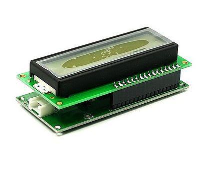
12 This consists of two parts, a module holding an 16 character by 2 line LCD, and the Grove itself(most may receive the two-units-soldered together-version). Before using your LCD Grove, download the library from: click Seeedstudio SerialLCD library. Then extract the SerialLCD-Library.zip folder and copy it into your Arduino libaries folder, usually located at..\arduino-xx\libraries. Please see project six described later on in this guide.for a detailed information on how to use your Serial LCD Grove, you can go to Grove - Serial LCD page,there are plenty of examples. Note: when you have connected Serial LCD to Base Shield and downloaded the example to the Seeeduino/arduino, make sure you reset the Seeeduino/arduino first, then push the Serial LCD's reset button. Protoshield
13 This Grove allows you to add your own circuitry or components to your Grove system prototypes. This allows you access to all four lines from the connector cable S0, S1, VCC and GND. There is also an extra normally-open button to take advantage of. The hole spacing makes using normal DIP-format ICs and other components very simple. You may wish to purchase more for future use in advance. Features Standardized scalable Jigsaw shape, unified 4 pin connector, screw hole grid, edge solder pad, reduce duplicate developing, reuse in different projects to reduce environment impact Compact size from 2cm*2 cm, seamless combination, surface mounting components, 2.0mm pitch cable Friendly easy buckled connection, dumb proof, various extension modes, open for DIY, libraries and demo codes Plentiful- large selection of common circuits from basic (button, LED) to professional sensor (Gyro, Compass), keep adding per demand, 3rd party contributions, reusable Community based satisfying needs through voting, democratized design, project and recipe sharing, profit sharing business pattern, Renting and Reuse Application Ideas Application1 Application2 Application3 Cautions The warnings and wrong operations possible cause dangerous. Schematic It is the schematic, the circuit about Eagle resource like.pdf should linked here in order to avoid memory exhausted. Specification May include key specification and other specifications. Pin definition and Rating
14 Mechanic Dimensions Usage Hardware Installation Here is how to assemble Stardle Kit with Starter bundle harness. For more infornation you can go to Starter bundle harness. Programming Includes important code snippet. Demo code like : Demo code { }

15 Example Now you should be familiar with your Base Shield and Grove units, so let's examine them in more detail with the following projects: Project One - Blink Project Two - Digital Input v1.0b Project Three Analog Input v1.0b Project Four Noise Maker Project Five Relay Control Project Six LCD Demonstration Project Seven - Temperature Project Eight - Thermostat Furthermore, if you are using a Seeeduino or Seeeduino Mega, make sure you have the switches set to 5V and auto, as such: This ensures the board is running at 5V DC from the USB cable, and that the board will auto-reset upon uploading your sketch. Otherwise you will have to manually reset your Seeeduino before the sketch starts operation.
Electronic Brick Starter Kit
 Electronic Brick Starter Kit Getting Started Guide v1.0 by Introduction Hello and thank you for purchasing the Electronic Brick Starter Pack from Little Bird Electronics. We hope that you will find learning
Layad Circuits Arduino Basic Kit B. Content Summary
 Layad Circuits This kit is a careful selection of sensors, displays, modules, an Arduino Uno, connectors and other essential parts meant to facilitate learning of the hardware and software components of
Bill of Materials: Turn Off the Lights Reminder PART NO
 Turn Off the Lights Reminder PART NO. 2209650 Have you ever woke up early in the morning to find out that the kids (or adults) in your home forgot to turn off the lights? I've had that happen a number
Intel Galileo gen 2 Board
 Intel Galileo gen 2 Board The Arduino Intel Galileo board is a microcontroller board based on the Intel Quark SoC X1000, a 32- bit Intel Pentium -class system on a chip (SoC). It is the first board based
Freeduino USB 1.0. Arduino Compatible Development Board Starter Guide. 1. Overview
 Freeduino USB 1.0 Arduino Compatible Development Board Starter Guide 1. Overview 1 Arduino is an open source embedded development platform consisting of a simple development board based on Atmel s AVR
OpenSprinkler v2.2u Build Instructions
 OpenSprinkler v2.2u Build Instructions (Note: all images below are 'clickable', in order for you to see the full-resolution details. ) Part 0: Parts Check Part 1: Soldering Part 2: Testing Part 3: Enclosure
ROBOTLINKING THE POWER SUPPLY LEARNING KIT TUTORIAL
 ROBOTLINKING THE POWER SUPPLY LEARNING KIT TUTORIAL 1 Preface About RobotLinking RobotLinking is a technology company focused on 3D Printer, Raspberry Pi and Arduino open source community development.
Shack Clock kit. U3S Rev 2 PCB 1. Introduction
 Shack Clock kit U3S Rev 2 PCB 1. Introduction Thank you for purchasing the QRP Labs Shack Clock kit. This clock uses the Ultimate3S QRSS/WSPR kit hardware, but a different firmware version. It can be used
keyestudio Keyestudio MEGA 2560 R3 Board
 Keyestudio MEGA 2560 R3 Board Introduction: Keyestudio Mega 2560 R3 is a microcontroller board based on the ATMEGA2560-16AU, fully compatible with ARDUINO MEGA 2560 REV3. It has 54 digital input/output
Rover 5. Explorer kit
 Rover 5 Explorer kit The explorer kit provides the perfect interface between your Rover 5 chassis and your micro-controller with all the hardware you need so you can start programming right away. PCB Features:
MilCandy. Release date: 9/20/2015. Version: 1.0. Wiki:
 MilCandy Release date: 9/20/2015 Version: 1.0 Wiki: http://www.seeedstudio.com/wiki/milcandy Bazaar: http://www.seeedstudio.com/depot/milcandy-the-easiest-grove-controller-p- 1104.html 1 Document Revision
AlphaBot2 robot building kit for Arduino
 AlphaBot2 robot building kit for Arduino SKU 110060864 Description This AlphaBot2 robot kit is designed to use with an Arduino compatible board UNO PLUS. It features rich common robot functions including
DEV16T. LCD Daughter board
 LCD Daughter board Table of Contents 1 Introduction...2 2 Features...3 3 Expansion Connectors...4 3.1 Daughter Board Connectors...4 4 LCD Display...5 5 Input Buttons S1 to S4...5 6 Buzzer...5 7 Connector
RedBoard Hookup Guide
 Page 1 of 11 RedBoard Hookup Guide CONTRIBUTORS: JIMB0 Introduction The Redboard is an Arduino-compatible development platform that enables quick-and-easy project prototyping. It can interact with real-world
Prototyping & Engineering Electronics Kits Basic Kit Guide
 Prototyping & Engineering Electronics Kits Basic Kit Guide odysseyboard.com Please refer to www.odysseyboard.com for a PDF updated version of this guide. Guide version 1.0, February, 2018. Copyright Odyssey
Adafruit HMC5883L Breakout - Triple-Axis Magnetometer Compass Sensor
 Adafruit HMC5883L Breakout - Triple-Axis Magnetometer Compass Sensor Created by lady ada Last updated on 2016-09-14 07:05:05 PM UTC Guide Contents Guide Contents Overview Pinouts Assembly Prepare the header
The ICU-Duino Arduino Shield!
 The ICU-Duino Arduino Shield! Brought to you by: ENGINEERINGSHOCK ELECTRONICS FEATURES: On Board PIR (Passive Infra-red) Motion Sensor Red Indicator LED Infra-red (IR) Sensor Large Prototyping Area with
8051 Intermidiate Development Board. Product Manual. Contents. 1) Overview 2) Features 3) Using the board 4) Troubleshooting and getting help
 Overview 2) Features 3) Using the board 4) Troubleshooting and getting help") 8051 Intermidiate Development Board Product Manual Contents 1) Overview 2) Features 3) Using the board 4) Troubleshooting and getting help 1. Overview 2. Features The board is built on a high quality FR-4(1.6
8051 Intermidiate Development Board Product Manual Contents 1) Overview 2) Features 3) Using the board 4) Troubleshooting and getting help 1. Overview 2. Features The board is built on a high quality FR-4(1.6
Web Site: Forums: forums.parallax.com Sales: Technical:
 Web Site: www.parallax.com Forums: forums.parallax.com Sales: sales@parallax.com Technical: support@parallax.com Office: (916) 624-8333 Fax: (916) 624-8003 Sales: (888) 512-1024 Tech Support: (888) 997-8267
GUIDE TO SP STARTER SHIELD (V3.0)
") OVERVIEW: The SP Starter shield provides a complete learning platform for beginners and newbies. The board is equipped with loads of sensors and components like relays, user button, LED, IR Remote and
OVERVIEW: The SP Starter shield provides a complete learning platform for beginners and newbies. The board is equipped with loads of sensors and components like relays, user button, LED, IR Remote and
OpenSprinkler v2.1u Build Instructions
 OpenSprinkler v2.1u Build Instructions (Note: all images below are 'clickable', in order for you to see the full-resolution details. ) Part 0: Parts Check Part 1: Soldering Part 2: Testing Part 3: Enclosure
University of Hull Department of Computer Science C4DI Interfacing with Arduinos
 Introduction Welcome to our Arduino hardware sessions. University of Hull Department of Computer Science C4DI Interfacing with Arduinos Vsn. 1.0 Rob Miles 2014 Please follow the instructions carefully.
Power Supply, Arduino MEGA 2560, and Stepper Motors Connections
 Power Supply, Arduino MEGA 2560, and Stepper Motors Connections By: Maram Sulimani Abstract: Arduino MEGA 2560 is required for this project to control the movement of the 3D printer axis and its extruder.
ARDUINO MEGA 2560 REV3 Code: A000067
 ARDUINO MEGA 2560 REV3 Code: A000067 The MEGA 2560 is designed for more complex projects. With 54 digital I/O pins, 16 analog inputs and a larger space for your sketch it is the recommended board for 3D
Alessandra de Vitis. Arduino
 Alessandra de Vitis Arduino Arduino types Alessandra de Vitis 2 Interfacing Interfacing represents the link between devices that operate with different physical quantities. Interface board or simply or
Adafruit VL53L0X Time of Flight Micro-LIDAR Distance Sensor Breakout
 Adafruit VL53L0X Time of Flight Micro-LIDAR Distance Sensor Breakout Created by lady ada Last updated on 2016-12-05 06:40:45 PM UTC Guide Contents Guide Contents Overview Sensing Capablities Pinouts Power
How-To #7: Assemble an H-bridge Circuit Board
 How-To #7: Assemble an H-bridge Circuit Board Making a DC motor turn is relatively easy: simply connect the motor's terminals to a power supply. But what if the motor is to be controlled by an Arduino,
How-To: Make an RGB combination door lock (Part 1)
") How-To: Make an RGB combination door lock (Part 1) Written By: Feitan 2017 www.botsbits.org Page 1 of 14 INTRODUCTION Part 2 can be found here 2017 www.botsbits.org Page 2 of 14 Step 1 How-To: Make an
How-To: Make an RGB combination door lock (Part 1) Written By: Feitan 2017 www.botsbits.org Page 1 of 14 INTRODUCTION Part 2 can be found here 2017 www.botsbits.org Page 2 of 14 Step 1 How-To: Make an
IOX-16 User s Manual. Version 1.00 April Overview
 UM Unified Microsystems IOX-16 User s Manual Version 1.00 April 2013 Overview The IOX-16 Arduino compatible shield is an easy way to add 16 additional digital Input/Output (I/O) lines to your Arduino system.
Insert the male, 90 angled, 2x10 connectors into the corresponding 2x10 sockets and put them in place, flat under the PCB. Solder.
 MC624 Assembly guide Safety warning The kits are main powered and use potentially lethal voltages. Under no circumstance should someone undertake the realisation of a kit unless he has full knowledge about
RC Tractor Guy Controller V2.1 Assembly Guide
 RC Tractor Guy Controller V. Assembly Guide Features 0 Push button inputs Dual axis thumb sticks with built-in push button Rotary encoders with built-in push button MCU Socket to suit Meduino Mega 560
Digital Pins and Constants
 Lesson Lesson : Digital Pins and Constants Digital Pins and Constants The Big Idea: This lesson is the first step toward learning to connect the Arduino to its surrounding world. You will connect lights
Laboratory 1 Introduction to the Arduino boards
 Laboratory 1 Introduction to the Arduino boards The set of Arduino development tools include µc (microcontroller) boards, accessories (peripheral modules, components etc.) and open source software tools
Dwarf Boards. DN001 : introduction, overview and reference
 Dwarf Boards DN001 : introduction, overview and reference (c) Van Ooijen Technische Informatica version 1.6 PICmicro, In-Circuit Serial Prograing and ICSP are registerd trademarks of Microchip Technology
Quicksilver 606 TR-606 CPU Upgrade
 Quicksilver 606 TR-606 CPU Upgrade D650C 128 Installation Guide Social Entropy Electronic Music Instruments TABLE OF CONTENTS WARNINGS... 1 OVERVIEW... 2 WHAT'S IN THE BOX... 3 OPENING THE TR-606 CASE...
Thank you for purchasing the RGB Multi-MCU base and driver board from SuperTech-IT and TheLEDCube.com
 CONGRATULATIONS Thank you for purchasing the RGB Multi-MCU base and driver board from SuperTech-IT and TheLEDCube.com In this document, MCU means Microcontroller such as the PIC32, ATmega328P, prototype
ARDUINO YÚN Code: A000008
 ARDUINO YÚN Code: A000008 Arduino YÚN is the perfect board to use when designing connected devices and, more in general, Internet of Things projects. It combines the power of Linux with the ease of use
Rapid40i PIC Prototyping PCB User Manual
 Description This is a PCB designed to facilitate the rapid prototyping of a device based on a 40 pin Microchip PIC microcontroller. To allow users to focus on their application, we take care of key housekeeping
AT42QT1010 Capacitive Touch Breakout Hookup Guide
 Page 1 of 7 AT42QT1010 Capacitive Touch Breakout Hookup Guide Introduction If you need to add user input without using a button, then a capacitive touch interface might be the answer. The AT42QT1010 Capacitive
Grove - Buzzer. Introduction. Features
 Grove - Buzzer Introduction The Grove - Buzzer module has a piezo buzzer as the main component. The piezo can be connected to digital outputs, and will emit a tone when the output is HIGH. Alternatively,
Shack Clock kit PCB Revision: QCU Rev 1 or QCU Rev 3
 1. Introduction Shack Clock kit PCB Revision: QCU Rev 1 or QCU Rev 3 Thank you for purchasing this QRP Labs Shack Clock kit. The kit uses the same PCB and bag of components as some other QRP Labs kits.
ARDUINO MINI 05 Code: A000087
 ARDUINO MINI 05 Code: A000087 The Arduino Mini is a very compact version of the Arduino Nano without an on board USB to Serial connection The Arduino Mini 05 is a small microcontroller board originally
AT42QT101X Capacitive Touch Breakout Hookup Guide
 Page 1 of 10 AT42QT101X Capacitive Touch Breakout Hookup Guide Introduction If you need to add user input without using a button, then a capacitive touch interface might be the answer. The AT42QT1010 and
Grove - Rotary Angle Sensor
 Grove - Rotary Angle Sensor Introduction 3.3V 5.0V Analog The rotary angle sensor produces analog output between 0 and Vcc (5V DC with Seeeduino) on its D1 connector. The D2 connector is not used. The
mi:node User Manual Element14 element14.com/minode 1 User Manual V3.1
 mi:node User Manual Element14 element14.com/minode 1 Table of Contents 1) Introduction... 3 1.1 Overview... 3 1.2 Features... 3 1.3 Kit Contents... 3 2) Getting Started... 5 2.1 The Connector Board...
Arduino ADK Rev.3 Board A000069
 Arduino ADK Rev.3 Board A000069 Overview The Arduino ADK is a microcontroller board based on the ATmega2560 (datasheet). It has a USB host interface to connect with Android based phones, based on the MAX3421e
ARDUINO LEONARDO ETH Code: A000022
 ARDUINO LEONARDO ETH Code: A000022 All the fun of a Leonardo, plus an Ethernet port to extend your project to the IoT world. You can control sensors and actuators via the internet as a client or server.
3. The circuit is composed of 1 set of Relay circuit.
 Part Number : Product Name : FK-FA1420 ONE CHANNEL 12V RELAY MODULE This is the experimental module for a relay controller as the fundamental controlling programming. It is adaptable or is able to upgrade
Transcendent Frequency Counter
 Transcendent Frequency Counter with blue 2 x 16 LCD display This manual will guide you how to assemble, test and operate this frequency counter KIT. Features: The transcendent counter has two input channels
Phi-connect for Arduino (connector board V1.9)
") Phi-connect for Arduino (connector board V1.9) Last reviewed on 3/29/2012 John Liu 1. Introduction... 2 2. Main features... 2 3. Parts list... 3 4. How to use... 4 5. Improving your Arduino experience
Phi-connect for Arduino (connector board V1.9) Last reviewed on 3/29/2012 John Liu 1. Introduction... 2 2. Main features... 2 3. Parts list... 3 4. How to use... 4 5. Improving your Arduino experience
Educato. Assembly Instructions
 Product Description The Educato is an Arduino compatible board that has about the functionality of the Arduino Uno. It also has the ability, however, to plug into a solderless breadboard and to have all
ARDUINO MEGA ADK REV3 Code: A000069
 ARDUINO MEGA ADK REV3 Code: A000069 OVERVIEW The Arduino MEGA ADK is a microcontroller board based on the ATmega2560. It has a USB host interface to connect with Android based phones, based on the MAX3421e
Adafruit BME280 Humidity + Barometric Pressure + Temperature Sensor Breakout
 Adafruit BME280 Humidity + Barometric Pressure + Temperature Sensor Breakout Created by lady ada Last updated on 2018-08-22 03:49:22 PM UTC Guide Contents Guide Contents Overview Pinouts Power Pins: SPI
DIRRS+ Digital Infra-Red Ranging System Ideal for robotics projects. Singles (SKU # Pack (SKU #35100)
") Ltd DIRRS+ Digital Infra-Red Ranging System Ideal for robotics projects a division of Singles (SKU #35090 4 Pack (SKU #35100) Infrared Distance Measurement 5V Output Signal 3 Output Modes Reliable Optics
Ltd DIRRS+ Digital Infra-Red Ranging System Ideal for robotics projects a division of Singles (SKU #35090 4 Pack (SKU #35100) Infrared Distance Measurement 5V Output Signal 3 Output Modes Reliable Optics
Arduino Uno. Arduino Uno R3 Front. Arduino Uno R2 Front
 Arduino Uno Arduino Uno R3 Front Arduino Uno R2 Front Arduino Uno SMD Arduino Uno R3 Back Arduino Uno Front Arduino Uno Back Overview The Arduino Uno is a microcontroller board based on the ATmega328 (datasheet).
Adafruit BMP280 Barometric Pressure + Temperature Sensor Breakout
 Adafruit BMP280 Barometric Pressure + Temperature Sensor Breakout Created by lady ada Last updated on 2017-12-09 06:21:37 PM UTC Guide Contents Guide Contents Overview Pinouts Power Pins: SPI Logic pins:
FTC200 & FTA/FTX Quick Installation & Jumper Setting Guide
 FTC200 & FTA/FTX Quick Installation & Jumper Setting Guide Accuthermo Technology Corp. Safety Note Please read this entire document before you begin connecting cables and assembling your system Failure
Rapid28iXL PIC Prototyping PCB User Manual
 Description Features This is a PCB designed to facilitate the rapid prototyping of a device based on a 28 pin Microchip PIC microcontroller. To allow users to focus on their application, we take care of
Module 003: Introduction to the Arduino/RedBoard
 Name/NetID: Points: /5 Module 003: Introduction to the Arduino/RedBoard Module Outline In this module you will be introduced to the microcontroller board included in your kit. You bought either An Arduino
Digital Flame 1.0 Kit
 Digital Flame 1.0 Kit Instruction Manual Eastern Voltage Research, LLC June 2012, Rev 1 1 http://www.easternvoltageresearch.com Introduction to the Digital Flame 1.0 Kit Thank you for purchasing the Digital
Phi-panel backpack assembly and keypad options Dr. John Liu 12/16/2012
 Phi-panel backpack assembly and keypad options Dr. John Liu 12/16/2012 1. Introduction:... 3 Currently available:... 3 2. Backpack assembly... 4 3. Connecting to a keypad... 6 4. Rotary encoder keypads...
A4988 Stepper Motor Driver Carrier, Black Edition
 A4988 Stepper Motor Driver Carrier, Black Edition A4988 stepper motor driver carrier, Black Edition, bottom view with dimensions. Overview This product is a carrier board or breakout board for Allegro
Halloween Pumpkinusing. Wednesday, October 17, 12
 Halloween Pumpkinusing Blink LED 1 What you will need: 1 MSP-EXP430G2 1 3 x 2 Breadboard 3 560 Ohm Resistors 3 LED s (in Red Color Range) 3 Male to female jumper wires 1 Double AA BatteryPack 2 AA Batteries
Propeller Project Board USB (#32810)
") Web Site: www.parallax.com Forums: forums.parallax.com Sales: sales@parallax.com Technical: support@parallax.com Office: (916) 624-8333 Fax: (916) 624-8003 Sales: (888) 512-1024 Tech Support: (888) 997-8267
Web Site: www.parallax.com Forums: forums.parallax.com Sales: sales@parallax.com Technical: support@parallax.com Office: (916) 624-8333 Fax: (916) 624-8003 Sales: (888) 512-1024 Tech Support: (888) 997-8267
ARDUINO LEONARDO WITH HEADERS Code: A000057
 ARDUINO LEONARDO WITH HEADERS Code: A000057 Similar to an Arduino UNO, can be recognized by computer as a mouse or keyboard. The Arduino Leonardo is a microcontroller board based on the ATmega32u4 (datasheet).
Atmel Microprocessor Programming With AVRISPmkii
 Atmel Microprocessor Programming With AVRISPmkii Purpose EE 400D - Senior Design Part of Electronics & Control Division Technical Training Series by Nicholas Lombardo October 13, 2015 The purpose of this
Rapid40iXL PIC Prototyping PCB User Manual
 Description This is a PCB designed to facilitate the rapid prototyping of a device based on a 40 pin Microchip PIC microcontroller. To allow users to focus on their application, we take care of key housekeeping
Colecovision 5v Memory Mod Installation
 Colecovision 5v Memory Mod Installation The Colecovision suffers from common failure points: the power supply, power switch, and 4116 DRAM. The power supply suffers from poor soldering, the power switch
How to use the Zduino LEE Module with the Trainer Board
 How to use the Zduino LEE Module with the Trainer Board Note: If you are going to use the Arduino/Zduino module for this distance training workshop, please download the Arduino software: 1. Connections
Laboratory of Sensors Engineering Sciences 9 CFU
 Laboratory of Sensors Engineering Sciences 9 CFU Contacts Alexandro Catini catini@ing.uniroma2.it Phone: +39 06 7259 7347 Department of Electronic Engineering First Floor - Room B1-07b Course Outline THEORY
ARDUINO INDUSTRIAL 1 01 Code: A000126
 ARDUINO INDUSTRIAL 1 01 Code: A000126 The Industrial 101 is a small form-factor YUN designed for product integration. OVERVIEW: Arduino Industrial 101 is an Evaluation board for Arduino 101 LGA module.
Thursday, September 15, electronic components
 electronic components a desktop computer relatively complex inside: screen (CRT) disk drive backup battery power supply connectors for: keyboard printer n more! Thursday, September 15, 2011 integrated
12v Power Controller Project Board
 12v Power Controller Project Board 12 Volt Power Controller Introduction This board provides three functions... DC power gate Low voltage disconnect Voltage / current display The typical usage for this
Adafruit Terminal Block Breakout FeatherWing
 Adafruit Terminal Block Breakout FeatherWing Created by lady ada Last updated on 2017-01-04 04:53:26 AM UTC Guide Contents Guide Contents Overview Pinouts Assembly Downloads Datasheets & Files Schematic
Arduino IDE The Developer Kit library The JeeLib library for RFM12 transceivers
 SKU: 810011 The aim of this project is to build a hydrogen powered remote temperature sensor. It is based on the Arduino, Developer Kit fuel cell shield, Maxim DS18B20 1 Wire temperature sensor, and the
CAUTION: TTL Only, Do Not Use ± 12 V RS-232
 DIRRS+ Digital Infra-Red Ranging System Ideal for robotics projects Singles (SKU #35090) 4 Pack (SKU #35100) Infrared Distance Measurement 5V Output Signal 3 Output Modes Reliable Optics Easy to use Open
University of Florida EEL 4744 Drs. Eric M. Schwartz, Karl Gugel & Tao Li Department of Electrical and Computer Engineering
 Page 1/9 Revision 1 OBJECTIVES In this document you will learn how to solder and to debug a board as you are building it. REQUIRED MATERIALS Website documents o UF 68HC12 Development Board Manual (board
solutions for teaching and learning
 RKP18Motor Component List and Instructions PCB layout Constructed PCB Schematic Diagram RKP18Motor Project PCB Page 1 Description The RKP18Motor project PCB has been designed to use PIC microcontrollers
Arduino shield kit. 1) Low Pass Filter (LPF) kit (available for LF/MF/HF/VHF bands 2,200m to 6m)
 Low Pass Filter (LPF) kit (available for LF/MF/HF/VHF bands 2,200m to 6m)") Arduino shield kit 1. Introduction The QRP Labs Arduino shield kit is a versatile shield that can be used for various purposes. Write your own Arduino sketch to define the functionality! For example: 1)
Arduino shield kit 1. Introduction The QRP Labs Arduino shield kit is a versatile shield that can be used for various purposes. Write your own Arduino sketch to define the functionality! For example: 1)
Arduino Programming. Arduino UNO & Innoesys Educational Shield
 Arduino Programming Arduino UNO & Innoesys Educational Shield www.devobox.com Electronic Components & Prototyping Tools 79 Leandrou, 10443, Athens +30 210 51 55 513, info@devobox.com ARDUINO UNO... 3 INNOESYS
ARDUINO MICRO WITHOUT HEADERS Code: A000093
 ARDUINO MICRO WITHOUT HEADERS Code: A000093 Arduino Micro is the smallest board of the family, easy to integrate it in everyday objects to make them interactive. The Micro is based on the ATmega32U4 microcontroller
Easy Kit Board Manual
 User s Manual, V1.0, June2008 Easy Kit Board Manual Easy Kit - XC88x Microcontrollers Edition 2008-06 Published by Infineon Technologies AG, 81726 München, Germany Infineon Technologies AG 2008. All Rights
Arduino Internals. Dale Wheat. Apress
 Arduino Internals Dale Wheat Apress Contents About the Authors About the Technical Reviewers Acknowledgments Preface xv xvi xvii xviii Chapter 1: Hardware 1 What Is an Arduino? 1 The Arduino Uno 2 Processor
Mayhew Labs. Extended ADC Shield User Manual
 Table of Contents: Introduction 1 Hardware Description 1 Pin Descriptions 2 Setting the SPI communication level 2 Setting User Defined pin usage 2 Freeing Up Pin 9 (BUSY) 2 Installing Input Filtering Capacitors
LCMM024: DRV8825 Stepper Motor Driver Carrier,
 LCMM024: DRV8825 Stepper Motor Driver Carrier, High Current The DRV8825 stepper motor driver carrier is a breakout board for TI s DRV8825 microstepping bipolar stepper motor driver. The module has a pinout
Advanced Lantern 1.0 Kit. Introduction to the Advanced Lantern 1.0 Kit
 Advanced LED Lantern 1.0 Instruction Manual Eastern Voltage Research, LLC Introduction to the Advanced Lantern 1.0 Kit Thank you for purchasing the Advanced Lantern 1.0 Kit. This kit is an advanced microprocessor
Assembly Instructions (8/14/2014) Your kit should contain the following items. If you find a part missing, please contact NeoLoch for a replacement.
 Your kit should contain the following items. If you find a part missing, please contact NeoLoch for a replacement.") NeoLoch NLT-28P-LCD-5S Assembly Instructions (8/14/2014) Your kit should contain the following items. If you find a part missing, please contact NeoLoch for a replacement. Kit contents: 1 Printed circuit
NeoLoch NLT-28P-LCD-5S Assembly Instructions (8/14/2014) Your kit should contain the following items. If you find a part missing, please contact NeoLoch for a replacement. Kit contents: 1 Printed circuit
TEMPERATURE SENSOR/FAN CONTROL BOARD USER'S MANUAL
 Sample page from the Temperature Sensor/Fan Control User s Manual: TEMPERATURE SENSOR/FAN CONTROL BOARD USER'S MANUAL Introduction: The Temperature Sensor/Fan Control Board is a compact, free-standing
Advanced Strobe 1.0 Kit
 Kit Instruction Manual Eastern Voltage Research, LLC December 2013, Rev 1 1 http://www.easternvoltageresearch.com Kit Introduction to the Kit Thank you for purchasing the Kit. If you are looking for a
Omega MP. Multi-Programming Shield for Atmel Microcontrollers. User Manual
 Omega MP Multi-Programming Shield for Atmel Microcontrollers User Manual Ω - Omega MCU Systems Copyright 2012 Contents Introduction...2 Omega MP main features:...2 Getting Started...3 Assumptions...3 1.
Adafruit INA219 Current Sensor Breakout
 Adafruit INA219 Current Sensor Breakout Created by Ladyada Last updated on 2013-09-12 10:15:19 AM EDT Guide Contents Guide Contents Overview Why the High Side? How does it work? Assembly Addressing the
Installing Sentor. Hardware Installation
 Remote base site monitoring and control Installing Sentor Hardware Installation Copyright 2000 Sentor Monitoring Systems Pty Ltd Contents: 1 Introduction... 1 2 Sentor GUI... 2 3 ST3000 Controller... 3
Physical Computing Self-Quiz
 Physical Computing Self-Quiz The following are questions you should be able to answer by the middle of the semeter in Introduction to Physical Computing. Give yourself 6.5 points for questions where you
IDUINO for maker s life. User Manual. For IDUINO development Board.
 User Manual For IDUINO development Board 1.Overview 1.1 what is Arduino? Arduino is an open-source prototyping platform based on easy-to-use hardware and software. Arduino boards are able to read inputs
Goal: We want to build an autonomous vehicle (robot)
") Goal: We want to build an autonomous vehicle (robot) This means it will have to think for itself, its going to need a brain Our robot s brain will be a tiny computer called a microcontroller Specifically
Goal: We want to build an autonomous vehicle (robot) This means it will have to think for itself, its going to need a brain Our robot s brain will be a tiny computer called a microcontroller Specifically
GRBL SHIELD FOR ARDUINO UNO USER MANUAL
 GRBL SHIELD FOR ARDUINO UNO USER MANUAL YRCNC 2017 Introduction Thanks for supporting us! Hope you will have many hours of fun using this shield and that plenty hours of issueless cutting! The main features
CDN502 HIGH DENSITY I/O ADAPTER USER GUIDE
 CDN502 HIGH DENSITY I/O ADAPTER USER GUIDE 13050201 (c) Copyright DIP Inc., 1996 DIP Inc. P.O. Box 9550 MORENO VALLEY, CA 92303 714-924-1730 CONTENTS DN502 PRODUCT OVERVIEW 1 DN502 INSTALLATION 1 POWER
Arduino IDE Geiger Counter
 Arduino IDE Geiger Counter DIY Kit ver. 2.00 RH-K-GK-2-A http://rhelectronics.net 1 This is ver.2.00 second edition of Geiger project based on Arduino IDE manufactured by RH Electronics http://rhelectronics.net
Objectives: Learn how to input and output analogue values Be able to see what the Arduino is thinking by sending numbers to the screen
 Objectives: Learn how to input and output analogue values Be able to see what the Arduino is thinking by sending numbers to the screen By the end of this session: You will know how to write a program to
Adafruit INA219 Current Sensor Breakout
 Adafruit INA219 Current Sensor Breakout Created by lady ada Last updated on 2018-01-17 05:25:30 PM UTC Guide Contents Guide Contents Overview Why the High Side? How does it work? Assembly Addressing the