JNIOR Series 4. A Network I/O Resource Utilizing the JAVA Platform. JNIOR Series 4 with 4 Relay Output Expansion Module. Version 5.
|
|
|
- Zoe Perkins
- 5 years ago
- Views:
Transcription
 933-9350 FAX (724) 443-3553 www.integpg.com JNIORsales@integpg.")
1 JNIOR Series 4 A Network I/O Resource Utilizing the JAVA Platform JNIOR Series 4 with 4 Relay Output Expansion Module Version 5.0 NOTE: JNIOR JANOS 1.7 or greater required INTEG Process Group, Inc East Hardies Rd, First Floor Gibsonia, PA PH (724) FAX (724) JNIORsales@integpg.com Last updated on: January 23, 2019
2 TABLE OF CONTENTS 1 Overview Viewing, Managing, Configuring and Controlling Viewing Relay Number Management Relay Module Replacement Configuring Controlling Specifications and Wiring ii
 that integrate automatically with the JNIOR Series 4 Models 410, 412, 414.")

 for use by the various JNIOR applications.")
3 INTEG Process Group, Inc. 1 Overview The JNIOR 4 Relay Output Expansion Module (4ROUT) provides an easy way to add more relays to the JNIOR. The 4ROUT adds four relays that can handle low or highvoltages (up to 240 VAC at 10 amps per relay) that integrate automatically with the JNIOR Series 4 Models 410, 412, 414. The expansion module is connected to the JNIOR via the supplied cable that is plugged in to the Sensor Port on each device. A JNIOR can have a total of 16 relay outputs so the JNIOR 410 can have two 4ROUTs, the JNIOR 412 one 4ROUT and the JNIOR 414 two 4ROUTs. The expansion modules are daisy-chained together. The module can be connected to the JNIOR with power OFF or ON, but the JNIOR should still be rebooted after adding a module in case any application will use the module addressing. The 4ROUT expansion module will be automatically integrated into the various JNIOR communication methods (Web page, JNIOR Protocol and Modbus) for use by the various JNIOR applications. Please see Section 3 of this manual for the wiring details. JNIOR Model 410 JNIOR A Network I/O Resource 4 ROUT Expansion Module 1

4 2 Viewing, Managing, Configuring and Controlling 2.1 Viewing The is viewed via the main JNIOR web page. The JNIOR web page allows the user to monitor, control and configure the JNIOR internal and external I/O. The Expansion Modules are viewed and controlled on the External page. Dynamic Configuration Pages (DCP) for the JNIOR Series 4 2


5 The 4ROUT will be displayed as shown below. The picture above and below are for a JNIOR 410 with 8 digital inputs and 8 relay outputs standard. The 4ROUT is automatically numbered relays 9 12 for the first 4ROUT expansion module in a 410. For a 412, it is numbered relays and for a 414 it is numbered relays


6 2.2 Relay Number Management Each expansion module for the JNIOR has a unique serial number that ends in two characters that identify the type of module. All relay expansion modules end in FB. The first 4ROUT module has _1 appended to its serial number. The second 4ROUT has _2 appended to its serial number. This is how the JNIOR operating system knows to apply relay numbers 9 12 to the first module and relays to the second module. 4


7 Alternatively, you can go to the Console tab (or a Telnet or Command Line session) and use the extern command to display the modules connected to the JNIOR. 5

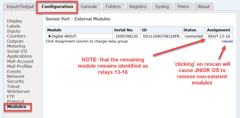
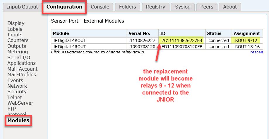
8 2.3 Relay Module Replacement Should you ever have to replace a module, since each expansion module for the JNIOR has a unique serial number, the JNIOR will actually remember the order number it assigned to that module. For example, _1 will always be relays 9 12 for the original unique ID number for that module, _2 will always be relays for its unique ID number. This is done so that if you have two modules and the first module fails, you want the second module to always remain the second module and use relay numbers Below is a series of screen pictures that show you what the modules look like on the Configuration tab Modules web page in the JNIOR main web page. The screen pictures show one module missing and how to replace it with a new module. NOTE: If you only have one expansion module, you would just click on the rescan link to remove the old one and THEN plug in the new one so it is assigned as the first module (_1) and relay numbers NOTE: If you have two modules and want to renumber them as to which relays they use, unplug both modules, click on rescan and then plug in one module at a time starting with the one you want used for relays 9-12 and then plug in the second module. 6
9 7

10 Alternatively, you could do all the above functions through the Console tab in the JNIOR web page or a Telnet/command line session using the extern and extern r commands as shown below. 8

11 2.4 Configuring The 4 Relay Output Expansion Module is configured via the main JNIOR web page. Go to the Configuration tab and the Modules page as shown below. Each change takes effect immediately. 9

12 2.5 Controlling The relay outputs can be controlled from the JNIOR web page on the External page. You can change the output status from OFF to ON or ON to OFF by clicking on the Toggle button. If you want to pulse an expansion relay output for a preset duration, you would need to do it via another device or application controlling the JNIOR. 10
13 3 Specifications and Wiring The 4 Relay Output Expansion Module (EXP ) specifications are as follows: General No power required draws power from the JNIOR Dimensions: 4.25 x 2.63 x 1.27 in (108 x 67 x 32 mm) Weight: 4 ounces (115 grams) Relay Outputs Quantity: 4 Type: SPST, Form C 1 Normally Open Contact, 1 Normally Closed Contact Range: up to 240 volts AC Contact Ratings: 10 Amps Pulse Resolution: 1 millisecond pulse increments Sensor Port Up to 2 expansion modules can be daisy-chained Each module comes with a cable for connecting to the Sensor Port. However, the Expansion Modules can be located up to 50 ft. from the JNIOR. A wiring diagram for the connector cable follows in this manual. Wiring Care should be used when wiring signals to the 4 Relay Output Expansion Module. Industry standard power and grounding methods should be followed. Relay Output Normally Open Common Normally Closed Controlled Device 11
14 Sensor Port Cable The JNIOR Expansion Modules come with a standard length cable. However, the Expansion Modules can be located up to 50 feet from the JNIOR. In these instances, the user must make a custom cable to connect the expansion module with the JNIOR. The pin out for the cable that connects the Sensor Port on the JNIOR with the Expansion Module is the same on both ends. The connector is a standard RJ-12 connector on both ends. Note: An RJ12 connector is the same size as an RJ11 connector except all 6 pins have copper pads to connect all 6 wires to the port. Please make sure that you orient the pins properly for each side of the cable. The cable will be twisted (or the one RJ12 connector will be upside down from the other) so that when you hold both ends of the cable side by side, the pin numbers will match. Please contact INTEG Process Group with any questions. Sensor Port Pin-Outs Use a 6 conductor wire and connect each colored wire to the same pin number on each connector. Pin Description 1 Voltage (5V Vcc) 2 GND 3 1-WIO (1-Wire Data) 4 GND (1-Wire Return) 5 NC (No Connection internally to the Expansion Module) 6 Unregulated DC Reference the following diagrams to determine the proper pin numbers of the connectors: Locking Tab face down 6 1 Locking Tab Locking Tab Position RJ12 Modular RJ12 Modular 12
15 Summary Thank you for purchasing the JNIOR. Hopefully this manual made the getting-to-know process of your new JNIOR very quick and easy. The JNIOR has many more wonderful tools and features available, and are explained in detail in the supplied documents on our website. Copyright Notice Trademarks Use Restrictions Copyright 2019 INTEG Process Group, Inc. All rights reserved. Every effort was made to make this manual as accurate and useful as practical at the time of the writing of this manual. However, all information is subject to change. Trademarks are the property of their respective holders. This User s Manual and the software contained in the JNIOR are copyrighted by INTEG Process Group, Inc. and may not be copied or reproduced without prior consent from INTEG Process Group, Inc. INTEG Process Group, Inc. is not responsible for any errors or omissions that may be contained in this manual. Please do not hesitate to contact our JNIOR team at INTEG Process Group, Inc. We can be reached via phone, fax or as follows: INTEG Process Group, Inc E. Hardies Road 1 st Floor Gibsonia, PA JNIORsales@integpg.com PH (724) extension 20 FAX (724)
JNIOR Series 4. A Network I/O Resource Utilizing the JAVA Platform. DMX Control Program. Release 1.0
 JNIOR Series 4 A Network I/O Resource Utilizing the JAVA Platform DMX Control Program Release 1.0 NOTE: This application works with the JNIOR 412DMX and JNIOR 410 INTEG Process Group, Inc. 2919 East Hardies
JNIOR Series 3 A Network I/O Resource Utilizing the JAVA Platform Getting Started Manual Release 3.3 NOTE: JNIOR OS 3.4 or greater required
 JNIOR Series 3 A Network I/O Resource Utilizing the JAVA Platform Getting Started Manual Release 3.3 NOTE: JNIOR OS 3.4 or greater required INTEG Process Group, Inc. 2919 East Hardies Rd, First Floor Gibsonia,
JNIOR Series 3. Serial-to-Ethernet Manual. A Network I/O Resource Utilizing the JAVA Platform. Release 3.0. NOTE: JNIOR OS 3.1 or greater required
 JNIOR Series 3 A Network I/O Resource Utilizing the JAVA Platform Serial-to-Ethernet Manual Release 3.0 NOTE: JNIOR OS 3.1 or greater required INTEG Process Group, Inc. 2919 East Hardies Rd, First Floor
JNIOR Series 4 A Network I/O Resource Utilizing the JAVA Platform Getting Started Manual Release 2.0 NOTE: JANOS OS 1.1 or greater required
 JNIOR Series 4 A Network I/O Resource Utilizing the JAVA Platform Getting Started Manual Release 2.0 NOTE: JANOS OS 1.1 or greater required INTEG Process Group, Inc. 2919 East Hardies Rd, First Floor Gibsonia,
Using Modbus with the JNIOR Series 4 Models 410/412/414. Last updated: March 31, 2016
 Using Modbus with the JNIOR Series 4 Models 410/412/414 Last updated: March 31, 2016 The following information describes the slight difference in utilizing the JNIOR Series 4 with Modbus when compared
JNIOR Series 3 A Network I/O Resource Utilizing the JAVA Platform Data Collector Manual Release 1.0 NOTE: JNIOR OS 3.4 or greater required
 JNIOR Series 3 A Network I/O Resource Utilizing the JAVA Platform Release 1.0 NOTE: JNIOR OS 3.4 or greater required INTEG Process Group, Inc. 2919 East Hardies Rd, First Floor Gibsonia, PA 15044 PH (724)
JNIOR Series 3. A Network I/O Resource Utilizing the JAVA Platform. Cinema.JNIOR Application Manual. Release 2.20
 JNIOR Series 3 A Network I/O Resource Utilizing the JAVA Platform Release 2.20 NOTE: For JNIOR 310 OS 3.5.422.1046 or greater required For JNIOR 312 OS 4.0.324.1407 or greater required INTEG Process Group,
POWERWISE INDAC SETUP MANUAL
 POWERWISE INDAC SETUP MANUAL REVISION: 2.2 INDAC & EMONITOR GATEWAY An installation guide for the PowerWise indac. 2013 PowerWise, Inc. This manual may contain proprietary information about the product
FX-2 Control Board ASY-360-XXX Setup and Configuration Guide
 FX-2 Control Board ASY-360-XXX Setup and Configuration Guide Micro Air Corporation Phone (609) 259-2636 124 Route 526. WWW.Microair.net Allentown NJ 08501 Fax (609) 259-6601 Table of Contents Introduction...
midon design A 1-Wire Multi-purpose Sensor 1WIO Figure 1 MD2083 As-Shipped August 23, WIO User Guide Version 1.
 A 1-Wire Multi-purpose Sensor 1WIO Figure 1 MD2083 As-Shipped August 23, 2009 1WIO User Guide Version 1.7 Page 1 of 14 1WIO User Guide Version 1.7 1. Table of Contents 1. Table of Contents...2 1.1. List
6222 Two Door Module Technical Operations Manual
 6222 Two Door Module Technical Operations Manual TABLE OF CONTENTS Specifications...3 Overview...4 Operations...5 Custom Access Mode...5 Standard Access Mode...5 Offline Access Mode...5 Offline Memory...5
Preliminary Product Overview
 Preliminary Product Overview Features 1.0 A per channel / 3.0 A Total Current Maximum Voltage (AC or DC): +150 V Low On-State Resistance < 1.0 Ω 10 GΩ Input to Output Isolation < 10us Switching Time High
Ink-Dot Series II Driver
 Instruction Sheet P/N 766B Ink-Dot Series II Driver Introduction See Figure. Ink-Dot Series II controllers can have from one to three driver modules. Any existing controller can easily be retrofit with
IEI emerge MicroNode Install and Setup Guide. Contents
 IEI emerge MicroNode Install and Setup Guide Contents Connecting power and the network to the MicroNode... 2 Using Power over Ethernet (PoE)... 3 or... 3 Using a 12 VDC power supply... 3 Connecting and
Remote Control for Inverter RC-300. Owner's Manual. Please read this manual BEFORE operating your RC-300 Remote Control
 Remote Control for Inverter RC-300 Owner's Manual Please read this manual BEFORE operating your RC-300 Remote Control OWNER'S MANUAL Index SECTION 1 Safety...3 SECTION 2 Description...3 SECTION 3 Layout
Installation & Operation Guide
 Installation & Operation Guide (Shown with optional Override Board Cover) KMD-5831 Programmable Loop Controller PLC-28 Direct Digital Controller 902-019-04B 1 Introduction This section provides a brief
Suprex RS-485 SPX-7500 Wired Reader-Extender
 Suprex RS-485 SPX-7500 Wired Reader-Extender Product Manual SPX-7500_MAN_181206 Cypress Integration Solutions 35 Years of Access Control Ingenuity CypressIntegration.com 2018 Cypress Computer Systems 1778
DIN-rail mountable relay unit for commercial control, power switching and home automation applications
 BARIX R6 DIN-rail mountable relay unit for commercial control, power switching and home automation applications PRODUCT MANUAL Version: 01.03 Date: 07/20/2005 For Firmware Version 2 Table of Contents
JANUARY 2000 TS800A TS801. MicroScanner
 JANUARY 2000 TS800A TS801 MicroScanner CUSTOMER SUPPORT INFORMATION Order toll-free in the U.S.: Call 877-877-BBOX (outside U.S. call 724-746-5500) FREE technical support 24 hours a day, 7 days a week:
UC-2000 Installation Manual Unicorn Computers Technology Limited
 UC2000 Installation Manual Copyright 2003. All rights reserved. Table of Contents Specifications 2 Enclosure for the UC2000 Controller 3 Unicorn Access Control System Configuration 4 UC2000 Controller
Hardware User s Manual. Digital Video Motion Detector DVMD1-X
 Hardware User s Manual Digital Video Motion Detector DVMD1-X Version 010 Revision A July, 2004 2395 Kenwood Drive Boulder, CO 80303 (303) 543-0440 TECHNICAL SPECIFICATIONS VENDOR Radiant Inc. http://www.dvmd.com
H3G-380 Production Description
 H3G-380 Production Description Designed for UPS battery strings of 15 to 48 batteries each of VRLA and Ni-Cd battery 1 Applications For strings of 15 to 48 batteries each Data Center IT Data Room 2 Product
Installation OVERVIEW
 Installation OVERVIEW The DEMCO GATE ACCESS CONTROL SYSTEM is designed to operate up to 4 gates, each with an IN KEYPAD and/or an OUT KEYPAD. Each gate is wired as illustrated in the drawing of a "TYPICAL
Connecting a Cisco Output Module
 CHAPTER 5 Overview The optional Cisco Output Module (Figure 5-1) is attached to a Cisco Physical Access Gateway or Cisco Reader Module to provide additional connections for up to 8 outputs, each of which
ADVANCED TECHNICAL MANUAL AAC1 SMALL SYSTEM CONTROL CONSOLE. Redefine your comfort zone.
 ADVANCED TECHNICAL MANUAL AAC1 SMALL SYSTEM CONTROL CONSOLE ATM ACC1 Table of Contents Safety Precautions... 3 Overview... 4 Specifications... 4 Installation... 5 Control Console Operation... 9 2 Advanced
MouldFlo Wiring Manual
 MouldFlo Wiring Manual Copyright (C) 2013 Move Innovation ApS http://www.moveinnovation.dk Table of Contents Introduction... 2 MouldFlo I/O (MFIO)... 3 Power Supply Connection... 4 Manifold Connector Ports...
WR-5e Remote Control
 1. Introduction WR-5e Remote Control The WR-5e is a microprocessor based serial data remote control unit for Ashly NE or NX products. Compatible products currently include Pema amplifiers, ne8800 and ne4800
Connector and Cable Specifications
 APPENDIX B This section describes the Catalyst 4224 Access Gateway Switch ports and the cables and adapters used to connect the switch to other devices. This section includes the following topics: Console
CONTROL PROTOCOL Motorized Projection Screens
 CONTROL PROTOCOL Motorized Projection Screens Table of Contents Overview... 3 Control Wiring Diagram... 3 IR Control... 4 Remote Button IR Hex Commands... 4 12 Volt DC Trigger... 5 Contact Closure and
NETRONICS HS3500 CONTROLLER
 NETRONICS HS3500 CONTROLLER CUSTOMER NAME CONTROLLER SERIAL # CONTROLLER PART # PERSONALITY SWITCH SETTINGS BULLET PRESS CONFIGURATION DELIVERY DATE Contact the factory for help setting up your application.
USB-Based 14-Channel Data-Acquisition Module
 USB-Based 14-Channel Data-Acquisition Module DLP-IO14 LEAD FREE FEATURES: 14 IO s: 0-5V Analog, Digital In/Out, Temperature Two Bipolar Analog Inputs; ±5V Input Range Max All Analog Inputs: Up to 30Ksps
TABLE OF CONTENTS. Communication Functions
 TABLE OF CONTENTS Chapter 1: Chapter 2: Chapter 3: Chapter 4: General Features....................................................... 1-1 Functions......................................................
MegaTrak MCU-9000 Harness Wiring
 MegaTrak MCU-9000 Harness Wiring Contents: 1. MCU9000 Connector Pin-Out Schematic 2. MCU9000 Connections when replacing an MCU3000 3. MCU9000 Connections Using 120VAC ( Hot ) Hook Switch (RS485 cable)
MOULDFLO WIRING MANUAL
 MOULDFLO WIRING MANUAL MOULDFLO A/S Copyright 2017 2860 Søborg - Denmark (DK) www.mouldflo.com 1 Contents Introduction... 3 Mouldflo I/O (MFIO)... 4 Power Supply Connection... 5 Manifold Connector Ports...
VS. 4 Game Selector INSTALL GUIDE
 VS. 4 Game Selector INSTALL GUIDE Each DK Selector includes the following items: 1. VS. 4 Game Selector PWB 2. 4 power cables 12, 14, 16 & 18 3. Ribbon daisy chain cable 4. Mounting feet and screws Some
IS-IR SAUNA ROUGH-IN- ###############
 IS-IR SAUNA ROUGH-IN- ############### 115 Bowes Rd, Unit 2, Concord, ON. L4K 1H7 Ph:905-738-4017 / 800-387-7029 sales@saunafin.com www.saunafin.com Infrared saunas are much more time consuming to install
MegaPoints Controllers Feedback Module.
 MegaPoints Controllers Feedback Module. 24 channel feedback module for version 2 MultiPanel Processors. User guide Features include No soldering truly plug and play Various sensor types o DCC and analogue
OpenSprinkler v2.1u Build Instructions
 OpenSprinkler v2.1u Build Instructions (Note: all images below are 'clickable', in order for you to see the full-resolution details. ) Part 0: Parts Check Part 1: Soldering Part 2: Testing Part 3: Enclosure
DK 4 Game Selector INSTALL GUIDE
 DK 4 Game Selector INSTALL GUIDE Each DK Selector includes the following items: 1. DK Selector PWB 2. 4 power cables 12, 14, 16 & 18 3. Ribbon daisy chain cable 4. Mounting feet and screws Some of the
STANDALONE PCI INTERFACE PACKAGE
 instrumentation and software for research STANDALONE PCI INTERFACE PACKAGE USER S MANUAL DOC 039 Rev 1.3 Copyright 2013 All Rights Reserved Med Associates Inc. P.O. Box 319 St. Albans, Vermont 05478 Phone:
Lantronix UDS-10 (CoBox) w/sielox Firmware B03.54 or greater Set-up, Installation, and FAQ Notes
 w/sielox Firmware B03.54 or greater Set-up, Installation, and FAQ Notes") Lantronix UDS-10 () w/sielox Firmware B03.54 or greater Set-up, Installation, and FAQ Notes June 2005 (Updated March 2006) Copyright 2006 by Sielox, LLC. Published by: Sielox 170 East Ninth Avenue Runnemede,
Lantronix UDS-10 () w/sielox Firmware B03.54 or greater Set-up, Installation, and FAQ Notes June 2005 (Updated March 2006) Copyright 2006 by Sielox, LLC. Published by: Sielox 170 East Ninth Avenue Runnemede,
Remote Control for Inverter RC-200. Manual. Please read this manual before operating your RC-200 Remote Control
 Remote Control for Inverter RC-200 Owner's Manual Please read this manual before operating your RC-200 Remote Control Owner's Manual Index SECTION 1 Safety...3 SECTION 2 Description...3 SECTION 3 Layout
Precision DMX Manual
 Precision DMX Manual Updated: December 4, 2012 The Precision DMX is a compact, low voltage, controllable LED fixture that can be connected to any DMX console or be programmed to run standalone without
PLCADD1616 User Guide 3/29/10. Overview
 PLCADD1616 User Guide 3/29/10 Overview The PLCADD1616 is a PLC expansion board used to add digital inputs and outputs to a compatible host PLC. The PLCADD1616 has 16 relay outputs and 16 optically isolated
Centroid ACORN CNC controller Specification and Use Guide Updated 8/3/17. Overview
 Centroid ACORN CNC controller Specification and Use Guide Updated 8//7 Overview ACORN is technically a CNC control breakout board for the BeagleBone Green or BeagleBone Black embedded computer the Beagle
AX3000 Platine Terminal Ethernet TCP/IP
 AX3000 Platine Terminal Ethernet TCP/IP Model 75E Installation Guide January 003 - Ref: I75EE0303-1 Model AX3000/M75E The reproduction of this material, in part or whole, is strictly prohibited. For additional
EVERSAN. Instruction Manual MODEL 9007/9008 TENNIS SCOREBOARD. Address: 34 Main Street, Whitesboro, NY 13492
 MODEL 9007/9008 TENNIS SCOREBOARD Instruction Manual Address: 34 Main Street, Whitesboro, NY 13492 Phone: 315-736-3967 Toll Free: 800-383-6060 Fax: 315-736-4058 SCOREBOARDS TIMERS MESSAGE SIGNS VIDEO DISPLAYS
Installation & Operation Guide
 Installation & Operation Guide Direct Digital VAV Controllers KMD-7001/7051 - VAV Terminal Units KMD-7002/7052 - Dual Duct VAV Units KMD-7003/7053 - Fan Induction Units 907-019-01C 1 Introduction This
This document describes the procedure for doing a power trace on the SM5 and Gauntlet Stepmills.
 SM5/Gauntlet Stepmill Power Trace Applies to: SM5 (150005) + Gauntlet (150015) This document describes the procedure for doing a power trace on the SM5 and Gauntlet Stepmills. Latest Rev. Warning: the
JNIOR. A Network I/O Resource Utilizing the JAVA Platform. JNIOR Support Tool Manual. Release 6.0
 JNIOR A Network I/O Resource Utilizing the JAVA Platform Release 6.0 Supports JNIOR Series 3 and 4 JNIOR OS 3.4 or greater required INTEG Process Group, Inc. 2919 East Hardies Rd, First Floor Gibsonia,
Application notes for Phybridge UniPhyer LB-UA2324 version 0.78P_B07 with Avaya Business Communication Manager (BCM) platforms release 5.0 Issue 1.
 platforms release 5.0 Issue 1.") Avaya Solution & Interoperability Test Lab Application notes for Phybridge UniPhyer LB-UA2324 version 0.78P_B07 with Avaya Business Communication Manager (BCM) platforms release 5.0 Issue 1.0 Abstract
Avaya Solution & Interoperability Test Lab Application notes for Phybridge UniPhyer LB-UA2324 version 0.78P_B07 with Avaya Business Communication Manager (BCM) platforms release 5.0 Issue 1.0 Abstract
PAD ANALOG / DIGITAL TRAINER OPERATOR S MANUAL
 PAD - 234 ANALOG / DIGITAL TRAINER OPERATOR S MANUAL Rev. 7/94 GENERAL OPERATING PROCEDURES 1. This manual should be read thoroughly before engaging in any experimentation. 2. As a general rule, NEVER
180 Series Keypad. Handbook. Revision 2.1
 180 Series Keypad Handbook Revision 2.1 Revision History Revision 1.0 Initial release Revision 2.0 Major update with addition of 180-40 Added 180-40 to document and various headings Note regarding unique
Connecting a Cisco Input Module
 CHAPTER 4 Overview The optional Cisco Input Module (Figure 4-1) is attached to a Cisco Physical Access Gateway or Cisco Reader Module to provide additional connections for up to ten input devices. Each
Installing the H2 -EBC(100), H2 -EBC -F or H4 -EBC( -F)
, H2 -EBC -F or H4 -EBC( -F)") 12 Installing the H2 -EBC(100), H2 -EBC -F or H4 -EBC( -F) In This Chapter Network Identifiers Setting the Module ID The H2 Series EBC DIP Switch The H4 Series EBC DIP Switch Inserting the H2 Series EBC
12 Installing the H2 -EBC(100), H2 -EBC -F or H4 -EBC( -F) In This Chapter Network Identifiers Setting the Module ID The H2 Series EBC DIP Switch The H4 Series EBC DIP Switch Inserting the H2 Series EBC
DPM-3221 Digital DC Power Meter with data logging capability.
 Introduction DPM-3221 Digital DC Power Meter with data logging capability. User Manual As a digital DC power meter, it measures the real time DC Voltage (5-60V), DC Current (0-200 A with the correct shunt),
RaceGrade Motorsport Keypad
 RaceGrade Motorsport Keypad Part # M KEYPAD 8H Part # M KEYPAD 15 USER MANUAL Version 1.3 RaceGrade Motorsport Keypad Copyright JGM Automotive Tooling 2011, 2012 MoTeC Systems USA and RaceGrade are registered
LAUREL. Laureate Dual-Channel Pulse Input Totalizer With Two Independently Scalable Input Channels & Presets ELECTRONICS, INC. Features.
 Description LAUREL ELECTRONICS, INC. Laureate Dual-Channel Pulse Input Totalizer With Two Independently Scalable Input Channels & Presets Features Frequencies up to 1 MHz Totals stored in non-volatile
CMB16D. 16 Channel DC Controller. User Manual May 25, 2008 V1.01 Copyright Light O Rama, Inc. 2007, 2008 CMB16D. Table of Contents
 Table of Contents 16 Channel DC Controller User Manual May 25, 2008 V1.01 Copyright Light O Rama, Inc. 2007, 2008 Introduction... 3 What s in the Box... 4 Applications... 4 First vs. Second Generation
MOD-MUX MODBUS TCP I/O PRODUCTS
 MOD-MUX MODBUS TCP I/O PRODUCTS Catalog and Design Guide P.O.Box 24 Stanfield 3613 SOUTH AFRICA Tel: +27 (031) 7028033 Fax: +27 (031) 7028041 Email: proconel@proconel.com Web: www.proconel.com 22/09/2009
Secured Series: Hub Plus Kit Single Door Controller Package Installation Manual
 Secured Series: Hub Plus Kit Single Door Controller Package Installation Manual This package is designed to simplify the connections to our Secured Series Hub Plus Controller. This will translate into
Foreword: The purpose of this document is to describe how to install and configure Neets 2 relay box with build-in power supply.
 Foreword: The purpose of this document is to describe how to install and configure Neets 2 relay box with build-in power supply. COPYRIGHT - All information contained in this manual is the intellectual
MODBUS RTU I/O Expansion Modules - Models C267, C277, and C287. Installation and Operations Manual Section 50
 MODBUS RTU I/O Expansion Modules - Models C267, C277, and C287 Installation and Operations Manual 00-02-0651 09-01-09 Section 50 In order to consistently bring you the highest quality, full featured products,
FX-2 Control Board ASY-360-XXX Setup and Configuration Guide
 FX-2 Control Board ASY-360-XXX Setup and Configuration Guide Micro Air Corporation Phone (609) 259-2636 124 Route 526. WWW.Microair.net Allentown NJ 08501 Fax (609) 259-6601 Table of Contents Introduction...
Ashly WR-5 Remote Control
 1. Introduction Ashly WR-5 Remote Control The WR-5 is a microprocessor based serial data remote control unit for Ashly NE or NX products. Compatible products currently include Pema amplifiers, ne8800 and
Branch PLC. Velocio s Branch PLC
 Velocio s Branch PLC Branch PLC The Branch PLC is a member of the Velocio s groundbreaking series of programmable logic controllers. These PLCs introduce revolutionary new concepts, capabilities, performance
NTI. KEEMUX Series. KEEMUX-P2 (2-Port PS/2 KVM Switch) INSTALLATION / USER GUIDE R NETWORK TECHNOLOGIES INCORPORATED
 INSTALLATION / USER GUIDE R NETWORK TECHNOLOGIES INCORPORATED") NTI R NETWORK TECHNOLOGIES INCORPORATED 1275 Danner Dr Aurora, OH 44202 Tel:330-562-7070 Fax:330-562-1999 www.nti1.com KEEMUX-P2 (2-Port PS/2 KVM Switch) INSTALLATION / USER GUIDE KEEMUX Series MAN049
NTI R NETWORK TECHNOLOGIES INCORPORATED 1275 Danner Dr Aurora, OH 44202 Tel:330-562-7070 Fax:330-562-1999 www.nti1.com KEEMUX-P2 (2-Port PS/2 KVM Switch) INSTALLATION / USER GUIDE KEEMUX Series MAN049
Chameleon Labs Model CPS-501 Powered Chassis
 Chameleon Labs Model CPS-501 Powered Chassis Owner s Manual 704 228 th Avenue NE, # 826 Sammamish, WA 98074 206-264-7602 www.chameleonlabs.com Revision C May 2010 Your Model CPS 501 Powered Chassis has
ACORN User Guide For Revision (Aka Acorn_rev3) Updated 1/23/17
 Updated 1/23/17") ACORN User Guide For Revision 171025 (Aka Acorn_rev3) Updated 1/23/17 Overview ACORN is technically a breakout board for the BeagleBone Green or BeagleBone Black embedded computer. The remainder of this
ACORN User Guide For Revision 171025 (Aka Acorn_rev3) Updated 1/23/17 Overview ACORN is technically a breakout board for the BeagleBone Green or BeagleBone Black embedded computer. The remainder of this
Neets Control QueBec P/N#: P/N#: User Manual
 Neets Control QueBec P/N#: 310-0011 P/N#: 310-0012 User Manual Foreword The purpose of this document is to describe how to install and configure the Neets Control QueBec II and Neets Control QueBec III.
Ultraflow 150DI 6Pt I/O Board OPERATIONS MANUAL
 Ultraflow 150DI 6Pt I/O Board OPERATIONS MANUAL Ultraflow 150DI SIX POINT IO.DOC 1 (This page intentionally left blank.) Ultraflow 150DI SIX POINT IO.DOC 2 DOCUMENT NUMBER: 1900-0110-01 REV B January 2014
Device: LDP This document Version: 1.0. Date: July Description: 80x08 1R1G LED Display Panel
 Device: LDP-8008 This document Version: 1.0 Date: July 2010 Description: 80x08 1R1G LED Display Panel Table of Contents Introduction... 3 Nomenclature... 3 Connections... 3 Power... 3 Pinouts... 4 Controlling
INTRODUCTION - DISPLAYS, DATA LOGGERS AND SOFTWARE
 INTRODUCTION - DISPLAYS, DATA LOGGERS AND SOFTWARE In times where energy conservation is a top priority for all progressive enterprises, the measurement of flow rates and consumption is becoming more and
EASY21x/23x-EVA. Evaluation Board for EASY21x / EASY23x PLC core. General Description. Ordering Information
 Evaluation Board for EASY21x / EASY23x PLC core General Description The is an evaluation board for the PLC core modules and PLC chips just like the EASY215 or EASY235 series. The board supports all the
NetGen Hardware Installation Guide. for NetGen Ethernet Door Controllers
 NetGen Hardware Installation Guide for NetGen Ethernet Door Controllers 0613 Table of Contents BLUEWAVE SYSTEM OVERVIEW...2 THE WI-FI LOCK AND SECURITY COMPANY...2 NETGEN DOOR CONTROLLERS...2 INSTALLATION
IPM500 Series QuickStart Manual
 IPM500 Series QuickStart Manual The Force of Innovation 10 Thomas Irvine, CA 92618 USA (949) 465-0900 FAX: (949) 465-0905 E-Mail: HTUfutek@futek.comUTH www.futek.com Manufacturer of Load Cells, Pressure
INTEGRATED SYSTEMS AND CONTROL, INC. User s Hardware Manual. PCMNET V 7. xx
 INTEGRATED SYSTEMS AND CONTROL, INC. User s Hardware Manual PCMNET V 7. xx INTEGRATED SYSTEMS AND CONTROLS, INC. PCMNET Users Manual Revised 2/4/2005 2003-2005 Integrated Systems and Control. Inc. PO Box
Ethernet to Digital I/O +RS232 +Switch
 4 Digital I/O Lines with RS232 Serial Port 4 Digital Ports independently can be In or Out 1 RS232 Serial Port 2 Ethernet Port User friendly software interface Simple web based configuration, monitoring
Revolutionizing control wiring
 SmartWire-DT Panel Wiring Solutions Revolutionizing control wiring 797-6925 Fax: (215) 221-1201 www.royalelectric.com SmartWire-DT Changing the way panels are wired. Reduce cost throughout the value chain.
E-ACLM-V E-ACLM-P12/8/18 AC LINE MONITORS Installation and Operation Manual
 NTI R NETWORK 1275 Danner Dr Tel:330-562-7070 TECHNOLOGIES Aurora, OH 44202 Fax:330-562-1999 INCORPORATED www.networktechinc.com ENVIROMUX Series E-ACLM-V E-ACLM-P12/8/18 AC LINE MONITORS Installation
Andover ContinuumTM Infinet II
 Andover ContinuumTM Infinet II The i80 Series controllers are designed for control of Air Handling Units, Roof Top Units, and other mechanical plant equipment. Features 0 Choose the i80 model with the
User Manual for DC6688SLP-USB
 User Manual for DC6688P-USB Document Revision 1.1 Jan, 2009 1 Revision History The following table shows the revision history for this document. Date Document Reviewed Remark Edited By Revision By Aug,
A-Series Controller & Logic Boards
 A-Series Controller & Logic Boards A-Series Controller General Port Connection Diagram 1. For LAN communication connect the Ethernet cable from the programming PC or network switch to the LAN port at the
RangerBOSS Network Ready Constant Monitor Model CM2800
 RangerBOSS Network Ready Constant Monitor Model CM2800 Instruction Manual Contents 1 Description CM2800 1 Features 1 2 Installation Installation Instructions 2 Installation Diagram 3 3 Operation Wrist
LAUREL. Laureate Pulse or Analog Input Batch Controller Automatic batch control for repetitive liquid fill operations ELECTRONICS, INC.
 Description LAUREL ELECTRONICS, INC. Laureate Pulse or Analog Input Batch Controller Automatic batch control for repetitive liquid fill operations Features Available for turbine flow meter pulse signals
Audisey REM-PACK-8. by Intelix
 Audisey REM-PACK-8 by Intelix Table of Contents Overview... 3 REM-PACK-8 Contents...3 Wiring the REM-PACK-8... 4 Determing the Cabling Schematic...4 Wiring with Twisted Pair and 18 Gauge Cable...5 Preparing
4 Connection and interface
 4 Connection and interface EXPOSED SIGNALS! DANGER Hazardous voltage levels may be present if using an open frame power supply to power the product. Failure to follow these instructions will result in
Connector and Cable Specifications
 APPENDIX B This appendix describes the Catalyst 3550 switch ports and the cables and adapters that you use to connect the switch to other devices. Connector Specifications These sections describe the connectors
Power Reduction Control Application Note. Power Reduction Interface Connection
 Power Reduction Control Application Note This document describes how to control and/or limit the inverter output power. This application note describes two options for power reduction control in SolarEdge
Touch Sense Controller
 Touch Sense Controller Paul Boston May 11, 2011 (Modified May 22, 2014) (Modified Dec 28, 2015) The Touch Sense Controller is a microprocessor-controlled circuit designed to provide a switch closure when
STATUS Shiloh Road Alpharetta, Georgia (770) FAX (770) Toll Free
 FAX (770) Toll Free") Instruction Manual Model 1582-45L Data Switch September 2010, Rev A REMOTE LOCAL SWITCH STATUS SELECT REMOTE LOCAL LOCAL SELECT CHANNEL SELECT POWER MODEL 1582 SWITCH CROSS TECHNOLOGIES, INC. Data, drawings,
Instruction Manual Model 1582-45L Data Switch September 2010, Rev A REMOTE LOCAL SWITCH STATUS SELECT REMOTE LOCAL LOCAL SELECT CHANNEL SELECT POWER MODEL 1582 SWITCH CROSS TECHNOLOGIES, INC. Data, drawings,
FUNCTIONAL DESCRIPTION
 All things connected Snaptekk www.snaptekk.com Connecting the DHT22 Sensor VCC: to VCC on module DIG: to DIG on module NC: No connection GND: to GND on module FUNCTIONAL DESCRIPTION The Temperature and
Advanced Distribution Cable Junction Box For Spectra RMS Molded-Case Circuit Breakers with Advanced Feature microentelliguard TM Trip Units
 GE Energy Industrial Solutions GEH-704 Installation Instructions Advanced Distribution Cable Junction Box For Spectra RMS Molded-Case Circuit Breakers with Advanced Feature microentelliguard TM Trip Units
Installation Instructions (KF-2000)
") VERSION 2005. 10 Installation Instructions (KF-2000) Keico Hightech, Inc. Installation Instructions KF-2000 Keico Hightech Ace Twin Tower I 12 th FL 212-1, Guro-Dong, Guro-Gu Phone +82-2-853-9000 Fax +82-2-830-7809
VERSION 2005. 10 Installation Instructions (KF-2000) Keico Hightech, Inc. Installation Instructions KF-2000 Keico Hightech Ace Twin Tower I 12 th FL 212-1, Guro-Dong, Guro-Gu Phone +82-2-853-9000 Fax +82-2-830-7809
USB-BASED 8-CHANNEL DATA ACQUISITION MODULE
 DLP-IO8-G *LEAD-FREE* USB-BASED 8-CHANNEL DATA ACQUISITION MODULE Features: 8 Channels: Digital I/O, Analog In, Temperature USB Port Powered USB 1.1 and 2.0 Compatible Interface Small Footprint; Easily
Three Phase Systems-International PC302-I/MTD
 Three Phase Systems-International PC302-I/MTD Enclosure Power Distribution Units (epdu ) sales@pulizzi.com 800-870-2248 Fax: 605-334-4999 Front RACK MOUNTED 19 x 3.4 (2U) x 8.5 with recess mounting Approximate
PXL-250 Tiger Controller
 PXL-0 Tiger Controller This quick start guide is made up of specification sheets, a DO/DON T list, basic installation drawings, first time power-on instructions, and short descriptions of key terms and
15P0102Q2 SINUS PENTA KEYPAD CONNECTED TO NETWORK RS485 USERS MANUAL
 15P0102Q2 SINUS PENTA KEYPAD CONNECTED TO NETWORK RS485 Upd. 08/06/04 R. 00 English This manual is integrant and essential to the product. Carefully read the instructions contained herein as they provide
Code Dynamics, Inc. Port Splitter
 Code Dynamics, Inc. Port Splitter Thank you for purchasing the Port Splitter. With this product, you can utilize a single Andover port for both the modem and PC connections. This device connects to the
Wiring and Configuration Instruction
 Wiring and Configuration Instruction This ENVIROMUX Sensor is intended for connection to an NTI ENVIROMUX-MINI-LXO /-16D / -5D/-2D for use in detecting changes in the environment. When properly connected,