PCM HARDWARE INSTALLATION GUIDE
|
|
|
- Rosanna Gibson
- 5 years ago
- Views:
Transcription

1 PCM HARDWARE INSTALLATION GUIDE
2
3 WELCOME! Congratulations on your purchase of a SADiE product; part of a range making up the most powerful hard disk editing systems in the world. These products are the result of over 10 years experience in the industry listening to our customers, taking on board their ideas, and providing for their needs. Our ethos of close customer contact, and free technical support and software upgrades has meant that customers not only buy a system but also make an investment that will reap dividends as the software expands. We feel confident that you will find using this system very enjoyable and hope that our products will be part of your production system for many years to come. As you take your system out of the box for the first time it is worth spending just a few moments reading this document, as it will help you to set up your system effectively and efficiently. Inside you ll find a complete packing list, help with connecting up your system and our troubleshooting guide to help overcome any initial problems. HARDWARE AND SOFTWARE INSTALLATION NOTE: A complete packing list for your new equipment is enclosed. Upon unpacking the equipment, please ensure that all the items listed are present. If you think that anything may be missing or has arrived in a damaged condition, please contact your supplier immediately SADiE digital audio workstation systems can be provided in a number of different configurations. The number and type of audio cards will all make a difference to how everything connects together. Most SADiE systems are provided as Turnkey packages, where the required options will be provided fitted into a SADiE Rack PC, with software pre-installed, configured, and ready to go. Alternatively you may have ordered just the audio cards and other options, and intend to install the hardware and software yourself. The first Getting Started section of this Installation Guide describes how to connect up a Turnkey system to its peripherals and breakout boxes, with some diagrams of example set-ups. The Technical Reference section will describe installation and specifications of individual cards and items, for reference purposes or for those that have purchased cards and software only. NOTE:- this guide provides technical information about the first revision of the PCM4 and PCM8 processors, known as TNG2 cards. These cards were discontinued in Getting Started Connections...1:1 Getting Started with SADiE5...1:5 SADiE on the Internet...1:6 Technical Reference PCM4 & PCM8...2:1 Installing SADiE5 Software...3:1 SADiE Hardware Control Panels...4:1 PCI CAT Timecode and Machine Control Card...5:1 Technical Specifications PCM4 & PCM8 I/P and O/P Specifications...6:1 Conformity Statements...6:5
4
5 Getting Started 1 - GETTING STARTED CONNECTIONS EXAMPLE 1 This shows a simple 8 track SADiE PCM8 turnkey. SADiE Breakout Box 800 Main SADiE Rack A.C. A.C. CAT Card PCM8 Card (1) Video Card Keyboard Mouse 1:1
6 Getting Started EXAMPLE 2 This shows a SADiE PCM4 turnkey. Analogue Inputs & Outputs 3 & 4 Analogue Inputs & Outputs 1 & 2 Digital Inputs & Outputs 1,2,3 & 4 Main SADiE Rack A.C. A.C. PCM4 card Video Card PCM4 digital expansion connector Keyboard Mouse 1:2
7 Getting Started EXAMPLE 3 This shows a 16-track SADiE PCM8 turnkey with options: Balanced analogue I/O option note that the 8in/8out XLR connectors on this replace the unbalanced jacks on the standard breakout panel. The 800B balanced breakout panel connects directly to the 44-way connector on the back of the PCM8 card, and provides a Y-lead connection onto which the standard 800 breakout box connects. NOTE: The diagram shows only one pair of breakout boxes connected. The second card (and 3 rd and 4 th for larger systems) will connect identically. Note also that the provided DC power supply connects to the balanced panel only. The unbalanced 800 panel has a connector for a power supply, but this is used only when it is used in conjunction with an optional Apogee AD bit AD/DA converter. Hardware controller pair (Jog and Fader panel) connect usually to 9-pin Port 1 on the standard 800 breakout box. Note that the undersides of both panels are printed with details of exactly how to connect the cables. 12VDC P.S.U. SADiE Balanced Breakout Box 800B to 9-pin 1(reverse of 800) SADiE Breakout Box 800 Main SADiE Rack A.C. A.C. Keyboard Mouse P.S.U. CAT Card PCM8 Card (2) PCM8 Card (1) Video Card Fader Panel Jog Panel 1:3
8 Getting Started A CLOSER LOOK AT THE PC CARDS Depending on the configuration of the system there are a number of different connectors you may see on the back panel of your computer. The drawings below should help you identify the cards in your system (you will NOT have all of these!). In a Turnkey system, the cards will also be identified by a label below the card slot at the rear of the main SADiE rack PC. PCM8 digital processor card Three female 15-way D-type connectors 1 1 Female 44-way D-type connector 3 2 Purpose: Connectors 1. To Breakout box(es) PCM4 digital processing card Purpose: Connectors The workhorse of the SADiE system. Provides digital audio processing. There may be up to 4 of these cards, depending on the I/O specified (i.e. 8, 16, 24, 32 tracks). The workhorse of the SADiE system. Provides digital audio processing. PCM4 occupies 2 x PC slots: one for the card, and the other for the breakout lead for digital I/O (i.e. connector number 3). The breakout leads are colour coded to match the colour label next to each multi-pin connector. 1. RED analogue in and out 1&2 2. YELLOW analogue in and out 3&4 3. BLUE digital in and out 1,2,3 & PCI CAT Card Purpose: To allow 9-pin machine control of compatible devices and provide SMPTE Timecode support. Connectors Male 25-way D-type connector 1. To breakout box (PCM8) or 9-pin breakout cable (PCM4) 2. Video Ref In 3. Video Ref Out 1:4
9 Getting Started GETTING STARTED WITH SADiE5 If you have purchased a new SADiE system you will find a SADiE5 software manual in the package. Please refer to Chapter 1 of the software manual, entitled Getting Started, which will take introduce you to the following areas of the system: HELP A general introduction to Digital Audio Editing An introduction to SADiE systems SADiE basics (Using Help, User Management, Starting SADiE, The Display, On-screen Help) Tutorial (Connections, Recording, Playing and Arranging the EDL, Saving, Editing, Mixing) A full on-line help file is available within the SADiE5 software. To access it, go to the Help menu at the top of the SADiE screen and select Help on SADiE5. The Help File is set out in the following chapters: Getting Started explains the concepts behind the system and the terminology used and gives you a quick guide to getting your system working for you. The Tutorial provides a step-by-step guide to editing the audio provided. We recommend that you follow this in order to save time later. Recording Using the Playlist Arranging an EDL Editing Mixing File Management Specific Applications contains notes on operations relevant to more specialised areas of work. For example: CD pre-mastering; Auto-conforming for video post-production and syncing film rushes. Customising SADiE explains the settings you can change to affect the way the system works or appears on the screen. 1:5
10 Getting Started SADiE ON THE INTERNET WEB SITES AND FAQ PAGES The SADiE website is at On this site you can find new product information, customer support information, FAQ lists, software download areas, contact and supplier information, news, company details, press releases, and details of forthcoming trade shows. SADiE USER FORUM ON THE INTERNET There is an independently run SADiE user forum on the Internet. Once you ve registered for the SADiE Web board you can view new and old messages online. Additionally you can subscribe to any or all of the forums on the Web board, and these messages will be ed to you directly. 1. To Register for the SADiE Web board: a. Using a web browser go to: SADiE b. At this front-door you can register as a New User. Once you ve applied, you will have to wait for a while and the Web board administrators will you a reply including your own password for the site. 2. Once you have received your password, return to the site and log-on using your address and the password provided. You will be able to access messages in three different ways: a. Directly on the Web board, where you have the ability to view ALL messages that have been posted. The Web board also has search facilities, so you can search to see if particular topics have already been discussed b. You can choose to receive new messages and reply to them via . Press the MORE button, then Mailing Lists, where you can sign up to receive messages from particular conferences via . c. Via a Newsreader. Point the Newsreader at webbd.nls.net and you will be offered the sections you have access to. These may include the Pro-Audio and Mastering boards; once you have access to the SADiE Web board you can also access the other areas hosted by the Web board. The Web board itself has further details of the facilities it offers under Help. 1:6
11 Hardware Installation 2 - HARDWARE INSTALLATION SADiE HARDWARE PLATFORMS There are 2 different PCM Series 5 hardware platforms on which the SADiE5 Software System can run: PCM4 and PCM8. Both offer similar facilities but with differing capabilities. Both are PC plug-in cards, and are based on a similar design. The installation of them is similar and so this document will describe the installation of all three, referring to them as SADiE cards, and only describing individual cards if their installation differs from the norm. Both PCM Series 5 cards are full-length PCI plug-in cards. The PCM8 card gives 8 channels of audio input and output, and can be optionally chained together so that up to four cards can operate together to give up to 32 channels of I/O. Each card utilises a 44-way D-type connector on the back panel of the card to connect to breakout boxes for digital and analogue audio I/O. In a multiple-card system, one card is known as the Master, the others (up to 3) are Slaves. A multi-card system must have one and only one Master card. A Slave card cannot function on it s own. PCM4 is similar to the PCM8 card, and is the same size. PCM4 provides 4 channels of audio I/O. These are connected via three 15-way D-Type connectors, which connect to XLR cable looms. Two of the 15-way connectors are on the PCM4 card itself, the other one is on a flying lead as described below. PCM4 is always a single card, and cannot be chained together to give more than 4 channels of I/O. INSTALLING THE SADiE CARD(S) INTO YOUR OWN PC It is a relatively simple task to install the SADiE hardware into your PC. However, it does involve taking the top off your PC and physically inserting the SADiE card(s). If you are unhappy delving into the innards of your PC then we would advise you to get the help of a friend who is experienced in this type of operation. In any case you will need to refer to your PC's User Manual for details on how to gain access to the expansion card slots. NOTE: SADiE cannot guarantee that the SADiE card or software will operate correctly in your PC. If you have any difficulties making SADiE operate, please contact your supplier or SADiE directly who will be happy to quote for attempting to make it work with your equipment, or for supplying a turnkey solution for you. INSTALLING THE SADiE CARD Be sure that power is removed before opening your PC and inserting (or removing) the expansion cards. Some PC s have an On/Off switch on the front of the unit, which does not necessarily remove ALL power! For safety, remove all power cables completely. For sake of ease and safety, you should disconnect the mouse, keyboard, monitor and any other cables at the back of the PC. The SADiE cards are full-length PCI cards, so you ll need to identify one or more (depending how many cards you are fitting) PCI expansion slots in your computer into which they can fit. Pay attention to ensuring that components on the PC motherboard are not in the way of the card when it is inserted. If such a component should come into contact with the SADiE board during operation, it may destroy both the card and your computer. Remove the blanking plate from the slot you have decided to use. If you are installing more than one PCM8 card for a multi-card system, the supplied leads will probably dictate that the cards should be in adjacent PCI slots. NOTE: It is imperative that your PC has a sufficient flow of cooling air to keep the SADiE boards at their proper operating temperature. Multiple card systems will generate more heat, and so particular care should be taken in these cases. If in doubt, you can purchase a specially made, rack-mount PC from SADiE. If in doubt about fitting the cards into your PC refer to your PC's Installation Guide, but pay particular attention to the following points: 2:1
12 Hardware Installation STATIC PRECAUTIONS The SADiE cards and other parts of your system are easily damaged by static electricity; do not remove the cards from their protective packaging until you have observed all static safety precautions. PLUG AND PLAY (PNP) You do not need to set any base address links or switches on the card prior to installation. The software installation is detailed in the next chapter. INSERTING THE CARD Place the card(s) into the slot(s). Take care that the blue plastic bracket on the card enters the correct card guide at the front of the PC and that the edge connector at the base of the card enters the receiving connector on the PC motherboard. You will have to use firm, but not excessive, pressure to insert the card fully. Once the card is properly in the slot, replace the screw that was holding the blank plate. This is the only physical restraint on the card and it protects the card and the PC from damage caused by the card moving when you plug a cable into one of its rear panel connectors or during transport. Try to avoid positioning the cables so that they block air holes or fans, as this will affect cooling efficiency. SPECIAL REQUIREMENTS FOR MULTI-CARD SYSTEMS:- One card will be a "Master" card and the others will be designated "Slave" usually by the letter S by the side of the serial number sticker. There is no other physical difference between the cards, although they are electrically different. When placing more than two PCM8 cards in a PC, the Master card MUST be on the "outside", thus the order of slots in the PC can be Master, Slave, Slave, Slave, or S, S, S, M, but not S,S,M,S, or S,M,S,S. Note also that the Master card cannot occupy a PCI slot that is shared with an ISA slot. INTERCONNECTIONS Digital Audio cable (PCM4 only) PCM4 is supplied with three Audio I/O looms for analogue and digital audio inputs and outputs. For details of the connection of these see below. At this stage you will need to consider whether you require digital audio connections to the PCM4. This is sent via the supplied 16way to 15way D-type cable, that has it s own PC fixing plate attached. For digital audio I/O to be possible, you will need to find another back-plane slot (or some other hole in the back of the PC) to take the 15-way D-type connector, and connect the dual-in-line connector on the other end onto connector J4 on the top edge of the PCM4 card. PCI CAT card - You may have an RS422/timecode card. This is a smaller PCI card, and the PCI CAT is an optional extra card for PCM Series 5 kit to provide timecode and 9-pin machine control, or for connecting the Hardware Controller option. For Information on connecting the PCI CAT card please see the PCI CAT Section of this guide. Multi-card interconnections - An interconnect cable will be supplied for multi-card systems, consisting of the appropriate number of 10-way IDC connectors. This connects to the 10-way connector J2, which is on the top of each PCM8 card (just behind the expansion board). The cards should be fitted in a Master-slave-slaveslave order, such that the Master card is on one end. Double-check the cables. Check that there are no trapped cables, everything is firmly connected, and in the correct orientation. Replace the lid of the computer. Reconnect the cables you disconnected at the start of this procedure and connect any cables that you want to run to the new cards. You re almost ready to power up the PC. What happens next depends on which operating system you are using, and this is described in the next chapter. 2:2
13 Hardware Installation CONNECTING THE AUDIO I/O PCM8 Each PCM8 card will have one or two breakout boxes, depending on whether the analogue balanced option has been purchased. The standard 800 breakout box has 4 male and 4 female XLR s on the face for AES/EBU in and out, plus 16 mono ¼ jacks for unbalanced analogue in and out. The rear of the 800 breakout box has connections for the CAT card, 9-pin ports and LTC in and out. The optional 800B breakout box has 8 male and 8 female XLR s for balanced analogue I/O. There are some diagrams in the Connections section above, which show how to connect the breakout boxes. If only an 800 breakout box is supplied, its captive lead connects directly to the rear of the SADiE card. If both breakout boxes are provided, then the 800B 44-way male D-type connects directly to the SADiE card, and the 800 connects to the female 44-way D-type connector which is attached near the main, male 44-way connector of the 800B. In either case, the PCI CAT card connects to rear of the 800 breakout box via a 25-way cable. Both ends use the same sex connector, but there is a difference: one end will be labelled BOB which connects onto the 800 breakout box, and the other will be labelled CAT which obviously connects onto the mating connector on the PCI CAT card. PCM4 Three audio looms have been provided for connection of audio inputs and outputs to PCM4. These will need to be connected to the three 15-way D-type connectors: two on the back of the PCM4 card, the third (for AES/EBU digital connections) is on the flying lead that was attached to J4 of the PCM4 as above. The leads have colour-coded shells on the 15-way connector, which match the insert of the D-type connectors on the PCM4 and flying lead. All cards have a label on the card to identify the colour. All leads have four XLR connectors (2 male 2 female) on one end and a 15-way male D-type connector at the other end. BLUE cable This is for AES/EBU digital connections. The 15-way connector attaches to the Blue 15- way D-type on the flying lead attached to J4 of the PCM4. RED cable YELLOW cable This is for Analogue Inputs and Outputs 1 and 2. The 15-way connector attaches to the Red 15-way D-type, which is the LOWER of the two on the back of the PCM4 card. This is for Analogue Inputs and Outputs 3 and 4. The 15-way connector attaches to the Yellow 15-way D-type, which is the UPPER of the two on the back of the PCM4 card. The XLR s on all three cables are labelled appropriately. Male XLR s will provide outputs and Females inputs in all cases. 2:3
14
15 Installing Software 3 - INSTALLING SOFTWARE INSTALLING DRIVER SOFTWARE You will need to log on as an administrator in order to install SADiE. When you first boot the PC after the SADiE hardware has been inserted in or connected via USB, Windows will notice the hardware change and offer to Plug and Play the hardware and search for a driver. Windows will report "Found new hardware multimedia controller Welcome to the Found new hardware wizard.". At this point you should press cancel in order to halt the plug and play. Windows will have installed a generic multi-media controller device at the moment, but installing the SADiE5 application software will resolve this and install the correct hardware driver. INSTALLING SADIE5 SOFTWARE You will have been provided with the installer for SADiE5. This is either on the standard V5 SOFTWARE INSTALLATION DISK with the blue yellow and orange 5 logo, or else it may have been downloaded from the SADiE Web site. INSTALLING FROM THE CD On inserting the V5 SOFTWARE INSTALLATION DISK, if you wait a short while, the Welcome to SADiE Version 5 menu will appear. If this doesn t happen, autorun may have been turned off on your CD drive; the quickest alternative way to get to this menu is to: Press the Windows "Start" button; select "Run" and type z:\autorun (where in this example z: is the letter of your CD drive). The Welcome menu will now appear. To install the SADiE5 software, select your hardware, then Install SADiE v5 Software and follow the installer instructions thereafter. A SADiE5 icon will appear on your desktop. Double-click this to run the SADiE software. DOWNLOADING SOFTWARE FROM THE INTERNET The most recent version of SADiE software is available for download on the SADiE World Wide Web page. It can be found at On the home page choose Support and then the Downloads link. Then download the current version of SADiE 5 Software. The download page offers you the SADiE software disks along with other downloads: release notes, installation notes, etc. and installers for plug-ins. To install the SADiE5 software, you will either be offered the chance to RUN the installer, straight after downloading it, or else you will need to navigate to the location on your hard drive that it was downloaded to, and double click on the installer file. Then follow the instructions on the screen, as above a shortcut will be placed on your desktop run this to run the SADiE application. UPDATING THE SOFTWARE You may be downloading the SADiE5 software installer in order to update the software to a newer version. Under normal circumstances, if you are updating to a newer version of software, then running the new installer will automatically uninstall the old version first, and then will install the new application files. 3:1
16 Installing Software There are sometimes occasions where this is not possible if you updating from a very old version or perhaps an intermediate beta-test version, then the software itself may tell you that you must manually uninstall first. If this happens:- Press the Start button, and choose Control Panel Select Add or Remove Programs Scroll down to find the entry for SADiE Software, select it, and press the Remove button Wait until that process has completed, then you can proceed to installing the new version of software. Note that uninstalling software does not affect any projects you have created, nor will it change any settings for the program; it merely removes the application files. INSTALLING PLUG-INS Software options and plug-ins come in two differing forms either:- a) they are part of the SADiE software and only require to be authorised, or b) they are third-party options which require an extra installer. Internal Options / SPW files The majority of the available options fall into the first category, and you will be supplied with an SPW file which may contain one or more authorisations codes. With a new system, any SPW files will be in the root directory of the supplied installation CD. On starting the SADIE software for the first time, you will be asked to supply this SPW and you should navigate to the CD when asked by the software. To install SPW files at other times: Run SADIE5 From the File menu, select Install Plug-in Options Then navigate to the supplied SPW file; the software will check the authorisations and report. Then close SAIDe and re-start the software before you use the plug-ins. Other plug-in Installers Currently (August 2008) the following options require a separate installer : All Cedar options (De-click96, De-Crackle96, De-Noise96, De-Thump96 and Retouch), Soundfield Surround Zone ProTools5 Interchange OMF Interchange With a new system, again, the authorisations for these will be in the root directory of the supplied software CD. The menus on the CD can be navigated to run the plug-in installer, and any authorisation codes found on the CD will install automatically. If you are downloading the plug-in installer, it will come in one of two forms a ZIP file or an EXE. The ProTools5 and OMF Interchange plug-ins are downloaded as zipped sets of files which must be extracted first before the installer can be run. The others are self-extracting EXE files which will start installing as you double-click to run them. If the plug-in installer asks for a password, it will have been supplied to you in a file called PWD??.TXT open this in Notepad, select the string of random characters, right click and copy to paste. Then when the installer asks, paste this string into the dialog box. If the installer doesn t ask for a password, it will have found it automatically (if the PWD??.TXT is in the root directory of the disk from which the installer is running, it will find the code). 3:2
17 Installing Software INSTALLATION TROUBLESHOOTING: Every PC configuration will be different, so it s difficult to give hard and fast rules about every possible situation that may occur. Some guidelines can be offered however. If you are not confident troubleshooting the PC installation or are unsure with any of the terms used in this section then you should consult someone who is, or contact SADiE customer support. You will need to be logged on as an Administrator to install SADiE software and fault find an installation. It is quite likely that modern operating systems will be able allocate the PC s resources in such a way as to avoid conflicts, however conflicts can still occur. The most likely conflict is either one of IRQ or interrupt or address a.k.a. Port address a.k.a. I/O address. PCI cards such as the PCM4 and PCM8 will have the IRQ and I/O address allocated by the operating system. The I/O address will be unique, but (in theory) IRQ s can be shared. The PCM4 and PCM8 are happy enough sharing an IRQ with each other or another PCI device. However, some other PCI devices may not be so happy to do this. Therefore, if in Device Manager, you see another device sharing an IRQ with the SADiE audio card, this is not necessarily a problem. However, because a shared IRQ is Windows -legal and the IRQ s are allocated by Windows, if there is a problem with the sharing of IRQ separating the devices can be very difficult. Sometimes a PC will allocate a particular IRQ to a particular PCI slot and thus changing the slot may cause the device to jump to another IRQ. 3:3
18
19 Hardware Control Panels 4 - HARDWARE CONTROL PANELS GENERAL The SADiE Hardware Controllers consist of two units that have mechanical cross sections similar to most common PC keyboards. The larger fader panel has eight assignable touch-sensitive motorised faders. The jog unit has one fader and a jog or shuttle wheel in the centre. The units can free stand and be arranged to suit the user. A special power supply and RS422 serial interface card (the PCI CAT card) are also needed. INSTALLATION The serial interface card must be installed inside the PC. See the PCI CAT installation sheet later in this document for details. CABLE CONNECTIONS Cable and power supply connection is detailed on the underside of both the jog and fader panels. See also the Connection diagrams earlier in this booklet. SOFTWARE INSTALLATION To turn on the Hardware Controllers inside the SADiE software: Under the View menu select Setup Window Choose the 9-pin Channels page on the left side of this window From the drop-down list at the side of the 9-pin port to which the controllers are connected, select Hardware Controller. The lights on the Hardware Controller will change and they will now be operational. Subsequently, starting SADiE will automatically search for the controllers on that 9-pin channel, and initialise them if they are there. If however, the controllers are switched off when SADiE boots, you will see an error message. You ll have to power them up, and then initialise them again in the 9-pin Setup page. POWER SUPPLY This is a fully certificated custom unit that must be supplied by SADiE. A label on its underside identifies it. Connect this unit to the local mains via its embedded IEC connector. Line voltage selection is automatic. There are no user adjustments. Allow air to circulate around this power supply for cooling purposes. USAGE There are no on-off power switches on any unit. To switch off (or force a reset) the power supply must be disconnected from the mains supply When power is applied, the fader and jog panels should display their ROM version number (internal control software) on their LED indicators. This display will change when SADiE gains control via the serial link The SADiE software User Manual and Help file give details throughout of hardware controller operation, and also contains a list of the keys and their functions. 4:1
20

21 PCI CAT 5 - PCI CAT INSTALLING A PCI CAT IN A PC If you have purchased your PCI CAT card as part of a Turnkey system then it will have already been installed into the system. Otherwise this section will lead you through installing the PCI CAT card into your system. This installation should only be carried out by a suitably qualified person. Do not remove the PCI CAT card from its protective packaging until indicated by these instructions. Please also observe full static safety precautions whilst handling the PCI CAT card, or touching any of the internal components of your computer. Ensure that the computer is switched off. If your computer has a power switch on the power supply unit (near to where the mains lead is connected), this should also be switched to the off position. Remove the computer s lid, and disconnect the lid-fan power lead to enable free and easy access to the computer s interior. Insert the PCI CAT card into a spare PCI slot of the computer motherboard. Connect the PCI CAT card to the PCM4 or PCM8 card with the PCI CAT SYNC lead. The 10- way connector attaches to the PCI CAT card by way of the 10-way box header on the PCI CAT card labelled SYNC. Ensure that the wires are at the rear of the connector (this is the end nearest to the MIDI connector). On the SADiE card, connect the red and black lead to LK1, with the black wire closest to the edge of the board (where the blue plastic bracket is). Connect the white and black lead to LK2, again with the black wire closest to the edge of the board. Screw the card into position and replace the computer s lid, ensuring that you reconnect the lid fan power lead. FOR WINDOWS 2000 OR WINDOWS XP Switch on the computer. Insert the supplied CD into the CD-ROM drive. After the computer starts up, log on to the system in the normal way and the Add new hardware wizard will be displayed. Click NEXT. The following page notifies you that it will search for drivers for PCI multimedia device. Click NEXT. The next page asks you what you want to do. Deselect all enabled radio buttons. Click NEXT. The final page has a large yellow question mark following the text Multimedia controller. Ensure that the radio button labelled Disable device is checked, and then click on the FINISH button. Restart the computer 5:1
22 PCI CAT SOFTWARE INSTALLATION Once the computer has finished booting, you must install or reinstall the SADiE software. Click on the START button, and select RUN. Double click on the folder and select the SADiE installer executable file. Click on the CLOSE button, and then click on OK. At certain points during the installation, various options are available depending on your hardware. If you do not have any of the hardware options shown installed in your system, click on NEXT to jump to the next screen. At the end of the copy phase of the installation process, a window will open displaying the icons used for the SADiE5 Software System. This window should be closed or moved in order to reveal the release notes window. Once you have read the release notes, click on YES. You must restart your computer so that changes to your computer s configuration may be registered; the next screen allows you to do this. Click on FINISH. After your computer has been re-started, SADiE5 will be ready for use. 5:2
23 Input/output specifications 6 - INPUT/OUTPUT SPECIFICATIONS GENERAL Figures apply for 32 khz, 44.1 khz, and 48 khz operating frequencies and, in the case of digital I/O, their multiples. They do not necessarily apply for minus 0.1%, chase lock, or varispeed rates. INPUTS DIGITAL INPUTS Each PCM8 card supports four two-channel digital inputs 1. A separate reference input is available for clock synchronisation purposes. PCM4 cards support two two-channel digital inputs at up to 96 khz sampling frequency. AES INPUTS XLR female connectors 2 : transformer balanced and isolated. Accept levels between 500mV and 10V peak-to-peak. Accept digital protocols to S/PDIF (consumer, IEC 958) or AES (professional AES3-1992) format, khz +10% Impedance: 110 No equalisation fitted. DIGITAL REFERENCE INPUT XLR female connector: transformer balanced and isolated. Accepts levels between 500mV and 10V peak-to-peak. Impedance: 100 ± 10% No equalisation fitted. NOTE: The PCM8 card will support AES digital reference for synchronisation purposes. It does not support word-clock or SDIF-2 synchronisation signals on input or output. All analogue XLR connectors are wired in the following order: Pin 1 Pin 2 Pin 3 Ground Positive, non-inverting hot Negative, inverting, cold ANALOGUE INPUTS 3 The PCM8 card supports 8 channels of analogue input. These signals appear on type 800 breakout box which is populated with ¼ mono jack connectors. Optionally a type 800B breakout box is available with female XLR connectors and electrically balanced receivers. 1 Eight channels digital inputs up to 88.2/96kHz or four channels at 174.4/192kHz 2 AES-3 pinout for digital audio XLR connectors. 7 Onboard A to D converters do not operate faster than 96kHz sample rate 6:1
24 Input/output specifications The PCM4 card supports 4 channels of analogue input. These signals appear on XLR cable looms supplied with the card. Nominal Level for peak digital audio (sine wave): o 800, unbalanced jacks +12dBu 4 o 800B, balanced XLR +12dBu o PCM4 balanced XLR +18dBu Conversion: o 24-bit 64-times over-sampling delta sigma converters, one per channel, simultaneous conversion, up to 96kHz sample rate. Input impedance: > 10k Frequency response: 20Hz - 20kHz, +/- 0.5dB, AC coupled. Total distortion and noise 5 with 1kHz applied at peak level: better than 90dB CMRR - > 50Hz TIMECODE INPUT XLR female located on back of type 800 breakout box. Electrically balanced Level: -17dBu to +7dBu Impedance: >10k VIDEO INPUT BNC connector located on back of PCI CAT card. PCI CAT card applies termination of 75 Sync pulses should be 300mV when terminated in 75 Two line vertical interval timecode can be read OUTPUTS DIGITAL OUTPUTS The PCM8 card provides four two-channel digital outputs 6. PCM4 provides two two-channel digital outputs. AES OUTPUTS XLR 3-pin male connectors, transformer balanced and isolated. Generates digital protocols to S/PDIF (consumer, IEC 958) or AES (professional AES3-1992) format, khz +10%, depending on software selection. Output level: 10V p-p (5V p-p when terminated in 110) Source impedance: 110 +/- 10% Symbol jitter < 20ns p-p RMS 4 0 dbu = 0dBm in 600 = Vrms Other levels are available by arrangement 5 S / (THD +N) 20Hz to 20kHz unweighted 6 Eight channels digital input at 88.2/96kHz or four channels at 174.4/192kHz 6:2
25 Input/output specifications ANALOGUE OUTPUTS 7 PCM8 supports 8 channels of analogue output. These signals appear on the type 800 breakout box which is populated with ¼ mono jack connectors. Optionally a type 800B breakout box is available with male XLR connectors and electrically balanced drivers. PCM4 supports 4 channels of analogue input. These signals appear on XLR cable looms supplied with the card. Level for peak digital audio (sine wave): o 800, unbalanced jacks +12dBu 8 o 800B, balanced XLR +12dBu o PCM4 balanced XLR +18dBu Conversion: 24-bit 64 times over-sampling delta sigma converters, one per channel, simultaneous conversion, up to 96kHz sample rate. Output impedance < 25 Frequency response: 20Hz - 20kHz, +/- 0.5dB, DC coupled. Total distortion and noise 9 with 1kHz applied at peak level: better than 90dB. TIMECODE OUTPUT Electrically balanced XLR male connector: Level: +3dBu Impedance: 25 SERIAL MACHINE CONTROL INTERFACE Four channel of serial interface are provided via four 9-pin female D connectors on the back of the type 800 breakout box. RS-422 compatible signalling Industry standard machine control pin out VIDEO OUTPUT BNC connector on CAT card E-E Source Impedance: 75 Performance when operating E-E (Electronics to Electronics, i.e. input is processed via input electronics then via output electronics without intervening recording or audio processing): DIGITAL INPUT TO OUTPUT Sample rate out is locked to sample rate in. Output protocol is independent of input protocol, i.e. can convert AES to S/PDIF or vice versa. User bits are not passed through system. 7 On board D to A converters do not function faster than 96kHz sample rate 8 0 dbu = 0dBm in 600 = Vrms Other levels are available by arrangement 9 S / (THD +N) 20Hz to 20kHz unweighted 6:3
26 Input/output specifications Output data equals input data, i.e. signal is unchanged (16-24 bit signals only, dithering off, with both input and output selected to match the test data). ANALOGUE PERFORMANCE, INPUT TO OUTPUT Frequency response: 20 Hz 20 khz, +0.5 db, AC coupled. Total distortion and noise 10 with 1 khz applied at peak level: better than 90 db below peak. EMPHASIS PCM Series 5 supports emphasis only in channel status sub-code. RECORDING METHOD No data compression is used. Recorded data is replayed unchanged if no processing is selected in software. POWER REQUIREMENTS (TURNKEY PCM SERIES 5 UNIT) 230 V or 11 +/- 10%, AC Hz. IEC line connector Steady-state power requirement < 300 W Fuse: 5 Amps (T) COMPLIANCE Case is CE marked: Conforms to the following standards: EN (EN55022); 1995 EN (EC 801-2,3,4); 1992 Following the provisions of the Low Voltage and EMC Council Directives: 73/23/EEC 89/336/EEC MECHANICAL SADiE turnkey: 19 rack mounting chassis. 4U. o Max dimensions: 485mm wide x 550mm deep x 180mm high. o Mass < 20 kg Breakout box 800 : 19 rack mounting chassis 1U o Max dimensions: 485mm wide x 280mm deep x 89mm high. o Mass < 3kg Breakout box 800B : 19 rack mounting chassis 1U o Max dimensions: 485mm wide x 280mm deep x 89mm high. o Mass: < 3kg 10 S / (THD +N) 20Hz to 20kHz unweighted 6:4
27 Input/output specifications CONFORMITY STATEMENTS EUROPEAN COMMUNITY - CE SADiE declares that its products conform to the following standards: EN (EN55022); 1995 EN (EC 801-2,3,4); 1992 Following the provisions of the Low Voltage and EMC Council Directives: 73/23/EEC 89/336/EEC UNITED STATES OF AMERICA - FCC SADiE declares that its products conform to the Part 15 of FCC rules concerning generation of and susceptibility to electromagnetic interference provided it is used unmodified and in accordance with manufacturers instructions 6:5
Getting Started Connections...1:1 Getting Started with SADiE6...1:5 SADiE on the Internet...1:6
 WELCOME! Congratulations on your purchase of a SADiE product; part of a range making up the most powerful hard disk editing systems in the world. These products are the result of over 15 years experience
Table Of Contents PCM-H64 HARDWARE INSTALLATION GUIDE... 2 WELCOME!...2 HARDWARE AND SOFTWARE INSTALLATION... 2 GETTING STARTED...
 Table Of Contents PCM-H64 HARDWARE INSTALLATION GUIDE... 2 WELCOME!...2 HARDWARE AND SOFTWARE INSTALLATION... 2 GETTING STARTED...3 CONNECTING YOUR PCM-H64... 3 ANALOG AND AES-EBU CONNECTIONS... 4 CHANNEL
AMU1-CHD+MK2 AUDIO MONITORING UNIT
 AMU1-CHD+MK2 AUDIO MONITORING UNIT Handbook TSL Products Units 1-2, First Avenue, Globe Park, Marlow, Bucks, SL7 1YA Telephone +44 (0)1628 564610 This Page is Blank SAFETY Installation. Unless otherwise
GETTING STARTED WITH THE SADIE LRX2
 2 GETTING STARTED WITH THE SADIE LRX2 CONNECTING THE LRX2 Your LRX2 will be supplied with a USB2 (A to B) cable, and a 12V DC power supply (PSU), with a mains plug appropriate to your geographical location.
SoundwebTM. Installation Guide
 111 SoundwebTM Soundweb TM 9010 Installation Guide Soundweb TM Regulatory Information v1.0 PW/JMK 21st March 1999 An example of this equipment has been tested and found to comply with the following European
GXD8 Operational Manual
 Genex Research Limited. GXD8 Operational Manual Revision 1.0 interstage Phistersvej 31, 2900 Hellerup, Danmark Telefon 3946 0000, fax 3946 0040 www.interstage.dk - pro audio with a smile GXD8 Operational
DANTE BRIDGE. Operation Manual
 DANTE BRIDGE Operation Manual Important Safety Instructions Important safety instructions Please carefully read following instructions and safety information and retain for future reference. Heed all warnings
BW-108. Building Wash BW-108. User Guide. Advanced LED Technology
 Building Wash User Guide Advanced LED Technology TABLE OF CONTENTS 1. Safety Instruction 2. Technical Specification 3. Change Beam Angle 4. Main Function 5. How To Control The Unit 6. Troubleshooting 7.
T L Audio INDIGO SERIES. User Manual PA-2001 VALVE PRE-AMPLIFIER. Tony Larking Professional Sales Limited, Letchworth, England.
 T L Audio INDIGO SERIES User Manual PA-2001 VALVE PRE-AMPLIFIER Tony Larking Professional Sales Limited, Letchworth, England. Tel: 01462 490600. International +44 1462 490600. Fax: 01462 490700. International
INTRODUCTION...1 FEATURES...1 PACKAGE CONTENTS... 1 TECHNICAL SPECIFICATIONS...2 SYSTEM REQUIREMENT..3 CABLE DIAGRAMS.3 PRODUCT DETAILS 4
 TABLE OF CONTENTS INTRODUCTION...1 FEATURES....1 PACKAGE CONTENTS... 1 TECHNICAL SPECIFICATIONS....2 SYSTEM REQUIREMENT..3 CABLE DIAGRAMS.3 PRODUCT DETAILS 4 HARDWARE INSTALLATION 5 USAGE 5 ON SCREEN DISPLAY
MONTANa. User s Guide
 MONTANa User s Guide Dakota, Montana, Sierra, SoDA, Tango24, and Zulu are trademarks of Frontier Design Group, LLC. All other trademarks and registered trademarks are the property of their respective holders.
User's Guide. Analog Expansion Board for DIGI96/8 Series, Hammerfall Series and HDSP /8 Channels, 24 Bit
 User's Guide Analog Expansion Board for DIGI96/8 Series, Hammerfall Series and HDSP 9652 4/8 Channels, 24 Bit Contents 1 Introduction... 3 2 Package Contents... 3 3 Hardware Requirements... 3 4 Technical
Copyright. Warning. Warning! Communications & Safety Regulation Information
 96i I/O Copyright 2006 Digidesign, a division of Avid Technology, Inc. All rights reserved. This guide may not be duplicated in whole or in part without the express written consent of Digidesign. Avid,
SMK525 / SMK585 / SMK595
 SMK525 / SMK585 / SMK595 RACK MOUNTABLE 1 / 8 / 16 PORT PS2 KVM SWITCH USER S MANUAL Rev 1.2 TABLE OF CONTENTS INTRODUCTION...1 FEATURES....1 PACKAGE CONTENTS..... 2 TECHNICAL SPECIFICATIONS...3 SYSTEM
L200 LINE/SUM/MIKE AMPLIFIER OPERATING AND MAINTENANCE MANUAL
 L200 LINE/SUM/MIKE AMPLIFIER OPERATING AND MAINTENANCE MANUAL Copyright 1997-2005, Audio Technologies Incorporated - Printed in USA DESCRIPTION Your L200 Dual Line/Buffer Amplifier is an inexpensive, high
DUAL MONO POWER AMPLIFIER INSTRUCTIONS FOR USE
 A3.2 CR DUAL MONO POWER AMPLIFIER C R MUSICAL FIDELITY A3.2 DUAL MONO POWER AMPLIFIER POWER INSTRUCTIONS FOR USE Thank you for purchasing the Musical Fidelity A3.2 CR Power Amplifier. Used properly and
AVC 2 AUTOMATIC VOLUME CONTROL USERS MANUAL
 AVC 2 AUTOMATIC VOLUME CONTROL USERS MANUAL GENERAL DETAIL The AVC2 will control a stereo channel to a preset maximum output level allowing the maximum sound level of a system to be controlled. The AVC2
SMK520 / SMK580 / SMK590 RACK MOUNTABLE 1 / 8 / 16 PORT PS2 KVM SWITCH USER S MANUAL
 SMK520 / SMK580 / SMK590 RACK MOUNTABLE 1 / 8 / 16 PORT PS2 KVM SWITCH USER S MANUAL Rev 1.1 TABLE OF CONTENTS INTRODUCTION...1 FEATURES....1 PACKAGE CONTENTS..... 2 TECHNICAL SPECIFICATIONS...3 SYSTEM
User s manual 19 1U RACKMOUNT CONTROL CENTER. Rack-KVM in-1 TABLE OF CONTENTS INTRODUCTION... (KVM switch, Keyboard, LCD display, touch pad)
") Rack-KVM9000 User s manual 4-in-1 (KVM switch, Keyboard, LCD display, touch pad) 19 1U RACKMOUNT CONTROL CENTER Rev 1.1 TABLE OF CONTENTS INTRODUCTION... FEATURES.... PACKAGE CONTENTS..... TECHNICAL SPECIFICATIONS...
Rack-KVM9000 User s manual 4-in-1 (KVM switch, Keyboard, LCD display, touch pad) 19 1U RACKMOUNT CONTROL CENTER Rev 1.1 TABLE OF CONTENTS INTRODUCTION... FEATURES.... PACKAGE CONTENTS..... TECHNICAL SPECIFICATIONS...
SYNERGY GLOBAL INC. Toll Free : Fax :
 SYNERGY GLOBAL INC Toll Free : 1-888-865-6888 Fax : 510-226-8968 Email : info@rackmountmart.com LCD1U15-03 series & LCD1U17-10 series User s manual 4-in-1 (KVM switch, Keyboard, LCD display, touch pad)
LED PANEL. User Manual Please read the instructions carefully before use LED-7TC. Innovation, Quality, Performance 15-
 LED PANEL LED-7TC Innovation, Quality, Performance User Manual Please read the instructions carefully before use 15- 9. Fixture Cleaning TABLE OF CONTENTS 1. Safety Instructions 2. Technical Specifications
FPA-1 Facility Port Adapter Installation Guide
 FPA- Facility Port Adapter Installation Guide FPA- Installation Guide v. Contents Introduction... 3 Mounting - mechanical... 4 Connections and Controls... 5 Block Diagram... Installation connections...
Check the contents of the package
 Read this first! UA-4FX Owner s Manual Copyright 2005 ROLAND CORPORATION All rights reserved. No part of this publication may be reproduced in any form without the written permission of ROLAND CORPORATION.
Installing the Cisco ADE 2130 and 2140 Series Appliance Hardware Options
 CHAPTER 4 Installing the Cisco ADE 2130 and 2140 Series Appliance Hardware Options This chapter provides instructions for installing, replacing, and removing various hardware options in your Cisco ADE
User Guide PRNT
 User Guide PRNT001073-01 www.focusrite.com CONTENTS About this User Guide...3 Box Contents...3 INTRODUCTION... 4 INSTALLATION GUIDE... 5 RedNet AM2 Connections and Features...5 Top Panel...5 Rear Panel...7
MAINTENANCE MANUAL. EDACS REDUNDANT POWER SUPPLY SYSTEM 350A1441P1 and P2 POWER MODULE CHASSIS 350A1441P3, P4, AND P5 POWER MODULES TABLE OF CONTENTS
 MAINTENANCE MANUAL EDACS REDUNDANT POWER SUPPLY SYSTEM 350A1441P1 and P2 POWER MODULE CHASSIS 350A1441P3, P4, AND P5 POWER MODULES TABLE OF CONTENTS SPECIFICATIONS*... 2 INTRODUCTION... 3 DESCRIPTION...
BS 287 DUAL CHANNEL POWER SUPPLY. User Manual. January 2017 V1.0
 BS 287 DUAL CHANNEL POWER SUPPLY User Manual January 2017 V1.0 Table of contents 1.0 SAFETY INSTRUCTIONS... 3 2.0 GENERAL DESCRIPTION PS 289... 4 3.0 MECHANICAL INSTALLATION... 5 4.0 MAINS POWER & SAFETY
MASELEC MTC-6 master transfer and monitor system
 MASELEC MTC-6 master transfer and monitor system http://www.maselec.com/ Mases Electronics Ltd. Bishopswood, Cannon Hill Close, Bray, Berks SL6 2DH, England. Tel/Fax: +44 (0) 1628-770 104. E-mail: leif@maselec.com
INSTRUCTION MANUAL RA 55 RACK ADAPTER RACK ADAPTER FOR MST SERIES POWER MODULES
 INSTRUCTION MANUAL RA 55 RACK ADAPTER RACK ADAPTER FOR MST SERIES POWER MODULES KEPCO INC. An ISO 9001 Company. MODEL RA 55 RACK ADAPTER ORDER NO. REV. NO. IMPORTANT NOTES: 1) This manual is valid for
T L Audio INDIGO SERIES. User Manual C-2021 VALVE COMPRESSOR. Tony Larking Professional Sales Limited, Letchworth, England.
 T L Audio INDIGO SERIES User Manual C-2021 VALVE COMPRESSOR Tony Larking Professional Sales Limited, Letchworth, England. Tel: 01462 490600. International +44 1462 490600. Fax: 01462 490700. International
Installation Manual. Mounting Instructions Mechanical Mounting. Luminato. Teleste Corporation
 Luminato Installation Manual Teleste Corporation Mounting Instructions Mechanical Mounting Luminato Mechanical Installation, agile_59300316, rev0044 Introduction 1 Contents Introduction 4 General... 4
BS 181 SINGLE CHANNEL POWER SUPPLY USER MANUAL
 BS 181 SINGLE CHANNEL POWER SUPPLY USER MANUAL August 2016 This product is designed and manufactured by: ASL Intercom B.V. Zonnebaan 42 3542 EG Utrecht The Netherlands Phone: +31 (0)30 2411901 Fax: +31
Online Manual Choose one of the following categories: Getting Started Guide Software User s Guides Technical Specifications Compliance Information
 Online Manual Choose one of the following categories: Getting Started Guide Software User s Guides Technical Specifications Compliance Information Part Number 137-40178-50 User s Guides Click on your product:
TOA ELECTRIC CO., LTD.
 Operating Instruction Manual TOA MIXING CONSOLE Model RX-31C TOA ELECTRIC CO., LTD. KOBE, JAPAN Contents General Description...2 Features...2 Front Panel...3 Rear Panel...4 Rack Mounting Instructions...5
epowerswitch-8 Power Management Master Slave User's Guide
 epowerswitch-8 Power Management Master Slave User's Guide epowerswitch-8 epowerswitch-8 is a couple of power control units made of a Master named epowerswitch-m8 and a slave named epowerswitch-s8. epowerswitch-m8
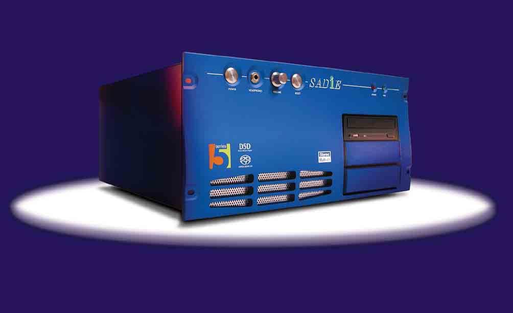
PCM-H64 SADiE PCM-H64 SADiE PCM-H64 TNG3 PCM-H64 SADiE Version 5
 DIGITAL PRECISION The PCM-H64 is an outstanding multitrack recorder/editor from SADiE that represents the pinnacle of many years of experience gained in designing high quality products for the professional
SAMURAI SCAN 50 LED-SC50D. User Guide. Innovation, Quality, Performance. Professional Entertainment Technology 19-
 SAMURAI SCAN 50 LED-SC50D Innovation, Quality, Performance User Guide Professional Entertainment Technology 19- EC Declaration of Conformity We declare that our products (lighting equipments) comply with
LED PANEL. User Manual Please read the instructions carefully before use LED-212RGB TABLE OF CONTENTS. 1. Safety Instructions
 TABLE OF CONTENTS LED PANEL 1. Safety Instructions 2. Technical Specifications 3. Installation 4. How to set the unit 5. How to control the fixture 6. DMX512 Configuration 7. DMX512 Connections 8. Troubleshooting
User's Guide. Analog Expansion Board for DIGI96/8 Series and Hammerfall Serie 4/8 Channels, 24 Bit
 User's Guide Analog Expansion Board for DIGI96/8 Series and Hammerfall Serie 4/8 Channels, 24 Bit Contents 1 Introduction...3 2 Package Contents...3 3 Hardware Requirements...3 4 Technical Specifications...3
DALLIS Product Information
 Product Information To obtain the latest documentation and software downloads, please visit: www.lawo.com/downloads Copyright All rights reserved. Permission to reprint or electronically reproduce any
TABLE OF CONTENTS Chapter 1 Introduction... 3 Chapter 2 Installation... 7 Chapter 3 Operation... 15
 TABLE OF CONTENTS Chapter 1 Introduction... 3 1.1 Features... 3 1.2 Package Contents... 4 1.3 Technical Specifications... 5 Chapter 2 Installation... 7 2.1 System Requirements... 7 2.2 Cable Diagrams...
4 / 8 / 16 PORT PS2 KVM SWITCH USER S MANUAL
 STACKABLE 4 / 8 / 16 PORT PS2 KVM SWITCH USER S MANUAL PC / Mac / Sun Multi Platform Rev 1.1 TABLE OF CONTENTS INTRODUCTION...1 FEATURES....1 PACKAGE CONTENTS..... 2 TECHNICAL SPECIFICATIONS...3 SYSTEM
The Discrete DAC. User Guide. Check our website for the most recent user guides, firmware, and drivers:
 The Discrete DAC User Guide Check our website for the most recent user guides, firmware, and drivers: www.msbtechnology.com Technical support email is: techsupport@msbtech.com 05.21.18 Technical specifications
LED W RGBA User Manual
 LED- 245-1W RGBA User Manual Please read the instructions carefully before use CONTENTS 1. Safety Instructions...2 2. Technical Specifications...3 3. How To Set The Unit...4 3.1 Control Panel...4 3.2 Main
OWNER S MANUAL GEQ 131/ 131LF GEQ 215/ 215LF GEQ 231. Single Channel 31 Band Graphic Equalizer. 2 Channel 15 Band Graphic Equalizer
 20 25 31.5 40 50 63 80 0 125 160 200 250 315 400 500 630 800 1K 1.25K 1.6K 2K 2.5K 3.15K 4K 5K 6.3K 8K K 12.5K 16K 20K +12 +6 +3 0-3 GEQ 131LF 5 31 BAND GRAPHIC EQUALIZER 15 40 60 7K 15K 22K BYPASS RANGE
POWER AMPLIFIER INSTRUCTIONS FOR USE
 INTRODUCTION A3 CR POWER AMPLIFIER INSTRUCTIONS FOR USE Thank you for purchasing the Musical Fidelity A3 CR power amplifier. Used properly and carefully, it should give you many years of outstanding musical
USER GUIDE 1 of 26 STAGEGRID 4000 User Guide rev.01 abr-18
 USER GUIDE 1 of 26 STAGEGRID 4000 User Guide rev.01 abr-18 SUMÁRIO About... 2 STAGEGRID 4000... 2 SoundGrid... 3 System Requirements... 3 Hardware... 4 Package Contents... 4 Rack Installation... 5 Setups...
Professional Entertainment Technology. imove 50SR. Innovation, Quality, Performance 21-
 Innovation, Quality, Performance 21- imove 50SR User Guide Professional Entertainment Technology EC Declaration of Conformity We declare that our products (lighting equipments) comply with the following
LED BEAM 300 LED-MB50. User. Guide. Professional Entertainment Technology
 LED BEAM 300 LED-MB50 Guide User Professional Entertainment Technology TABLE OF CONTENTS 1. Safety Instruction 2. Technical Specification 3. How To Set The Unit 4. How To Control The Unit 5. Troubleshooting
INSTRUCTION MANUAL RA 59 RACK ADAPTER. 1) This manual is valid for the following Model and associated serial numbers: MODEL SERIAL NO. REV. NO.
 This manual is valid for the following Model and associated serial numbers: MODEL SERIAL NO. REV. NO.") INSTRUCTION MANUAL RA 59 RACK ADAPTER KEPCO INC. An ISO 9001 Company. MODEL RA 59 RACK ADAPTER ORDER NO. REV. NO. IMPORTANT NOTES: 1) This manual is valid for the following Model and associated serial
INSTRUCTION MANUAL RA 59 RACK ADAPTER KEPCO INC. An ISO 9001 Company. MODEL RA 59 RACK ADAPTER ORDER NO. REV. NO. IMPORTANT NOTES: 1) This manual is valid for the following Model and associated serial
Professional Entertainment Technology LED BEAM 300 LED-MB50. Innovation, Quality, Performance 23-
 Innovation, Quality, Performance 23- LED BEAM 300 LED-MB50 User Guide Professional Entertainment Technology EC Declaration of Conformity We declare that our products (lighting equipments) comply with the
TRC-190 User s Manual
 User s Manual Edition 3.2, May 2017 www.moxa.com/product 2017 Moxa Inc. All rights reserved. User s Manual The software described in this manual is furnished under a license agreement and may be used only
Professional Entertainment Technology LED BEAM 300 LED-MB50. User. Guide
 Professional Entertainment Technology LED BEAM 300 LED-MB50 Guide User 1- 1. Safety Instruction WARNING Please read carefully the instruction, which includes important information about the installation,
Quick Start Guide. Quick Start Guide - 0
 Quick Start Guide 0404 Quick Start Guide - 0 1- Introduction Creative Professional Thank you for purchasing the E-MU 0404 Digital Audio System. We ve designed this E-MU Product to be logical, intuitive
Introducing the SoundWave 7.1 PCI. The SoundWave 7.1 PCI transforms your PC into a home theater system with multi-channel surround sound.
 SoundWave 7.1 PCI Quick Installation Guide Introducing the SoundWave 7.1 PCI The SoundWave 7.1 PCI transforms your PC into a home theater system with multi-channel surround sound. Features Compliant with
Timecode Transcoder. Artistic Licence (UK) Ltd. Software Version V3.2 Manual Revision V1.07
 Ltd. Software Version V3.2 Manual Revision V1.07") Timecode Transcoder Artistic Licence (UK) Ltd. Software Version V3.2 Manual Revision V1.07 Artistic Licence Product Registration Form Product: Serial No. Timecode Transcoder Version No. Date Purchased.
Timecode Transcoder Artistic Licence (UK) Ltd. Software Version V3.2 Manual Revision V1.07 Artistic Licence Product Registration Form Product: Serial No. Timecode Transcoder Version No. Date Purchased.
LoLa881 LoLa Professional Multichannel Sound Cards. User manual
 LoLa881 LoLa16161 Professional Multichannel Sound Cards For technical support please contact your system supplier Digigram S.A. 82/84 Allée Galilée, 38330 Montbonnot-Saint-Martin, FRANCE Tel: +33 (0)4
PIX 515/515E. PIX 515/515E Product Overview CHAPTER
 CHAPTER 4 PIX 515/515E This chapter describes how to install the PIX 515/515E, and includes the following sections: PIX 515/515E Product Overview Installing a PIX 515/515E PIX 515/515E Feature Licenses
MADI-PC MADI RECORDING SYSTEM
 MADI-PC MADI RECORDING SYSTEM USER MANUAL V1.0 1 P a g e Table of Contents INTRODUCTION... 3 IMPORTANT SAFETLY PRECAUTIONS... 4 General Safety... 4 Caution... 4 Power Safety... 5 Installation Notes...
General-Purpose 8-Slot Chassis for PXI
 NI Series 0 to 55 C extended temperature range () 43 dba acoustic emissions (Q) Accept both 3U PXI and CompactPCI modules Comply with all PXI and CompactPCI Specifications Low-jitter internal 10 MHz reference
Upgrading a 2U CHP to an i7 Quad Core SBC
 Upgrading a 2U CHP to an i7 Quad Core SBC 1. Parts required: i7 SBC Slim line SATA DVD drive Combined SATA data and power cable for slim-line optical drive Serial port ribbon cable - 9way D male to 10
DM200 DIGITAL AUDIO MONITOR OPERATION AND MAINTENANCE MANUAL
 DM200 DIGITAL AUDIO MONITOR OPERATION AND MAINTENANCE MANUAL Copyright 1997-2005, Audio Technologies Incorporated - Printed in USA DESCRIPTION The DM200 monitors AES/EBU, IEC958 and S/PDIF formatted digital
MODEL 805 USER MANUAL
 MODEL 805 USER MANUAL All Rights Reserved Page 1 of 12 UNPACKING & INSPECTION Save all packing materials they are required for returns and warranty service. Inspect the 805 and packing materials for any
TitanSDR Receiver. Installation Manual v.2.0e
 TitanSDR Receiver Installation Manual v.2.0e Enablia S.r.l. (Italy) 2014 Before using the receiver, read carefully this Manual. Correct Disposal of This Product (Waste Electrical & Electronic Equipment)
8380 RPC Return Path Combiner. User s Guide
 8380 RPC Return Path Combiner User s Guide Notice Every effort was made to ensure that the information in this manual was accurate at the time of printing. However, information is subject to change without
Your Rackmount Display Solution. 1U Keyboard / Monitor + 8 / 16 Ports. BHK Black Hawk Series USER S MANUAL. Ver.1
 Your Rackmount Display Solution 1U Keyboard / Monitor + 8 / 16 Ports BHK Black Hawk Series USER S MANUAL Ver.1 Content Specification....3 Rackmount Installation......4 Product Detail 5 On Screen Display.....6
Audio I/O 1U Manual. Audio I/O 1U System. Dual Balanced Line Audio Input and Balanced Line Audio Output. Manual Revision:
 Audio I/O 1U System Dual Balanced Line Audio Input and Balanced Line Audio Output Manual Revision: 2018.09.13 Table of Contents Table of Contents Compliance Overview Features System Installation Before
GAMBIT DAC2 FIREWIRE DAC OPERATING MANUAL
 GAMBIT DAC2 FIREWIRE DAC OPERATING MANUAL Daniel Weiss Engineering Ltd., Florastr. 42, CH-8610 Uster Page 1 of 7 Congratulations on purchasing the Weiss Gambit Series DAC2 D/A Converter! The DAC2 is a
Auricon 4.4. Manual ABN
 ABN 66 169 561 871 Auricon 4.4 Manual Overview The Auricon 4.4 is a professional-quality audio input-output card designed in Australia by Innes Corporation. It is supplied with a Windows WDM driver to
MC 11 EB-2 Power supply cabinet with external bus, AC version
 MC 11 EB-2 Power supply cabinet with external bus, AC version USER/MAINTENANCE MANUAL 1 SLOT 0 SLOT 1 SLOT 2 SLOT 3 SLOT 4 SLOT 5 SLOT 6 SLOT 7 SLOT 8 SLOT 9 SLOT 10 SLOT 11 EB-2 (a) MC11 (b) (c) Figures
USER MANUAL. VS Port RS-422 Matrix Switcher MODEL: P/N: Rev 5
 KRAMER ELECTRONICS LTD. USER MANUAL MODEL: VS-4228 8-Port RS-422 Matrix Switcher P/N: 2900-0033 Rev 5 Contents 1 Introduction 1 2 Getting Started 2 2.1 Achieving the Best Performance 2 2.2 Safety Instructions
User Manual Controller. Automation and Router Control.
 User Manual 2460 Controller Automation and Router Control www.s-a-m.com 2460 Controller User Manual www.s-a-m.com Contents Contents 1. Information and Notices.................................................
PXR 1506 / WATT MIXER AMPLIFIER
 PXR 1506 / 1508 150-WATT MIXER AMPLIFIER Operating Manual www.peavey.com ENGLISH PXR 1506 / 1508 150-Watt, 8-Channel Mixer Amplifier Designed with the latest Peavey technology, the PXR 1506 / 1508 powered
Studer D21m. I/O System Components. Condensed Information
 Studer D21m I/O System Components Condensed Information 2 The D21m I/O System The D21m I/O system provides very cost-effective inputs and outputs with maximum flexibility while maintaining the well-known
F1000 User's Manual. (Version: V1.01)
") (Version: V1.01) Contents Chapter 1 Overview... 2 Chapter 2 Installation... 3 2.1 Installation guide... 3 2.1.1 Installation position... 3 2.1.2 NEMA4 standard installation... 3 2.1.3 Environment precautions...
(Version: V1.01) Contents Chapter 1 Overview... 2 Chapter 2 Installation... 3 2.1 Installation guide... 3 2.1.1 Installation position... 3 2.1.2 NEMA4 standard installation... 3 2.1.3 Environment precautions...
AMP20. User Manual.
 AMP20 User Manual www.audac.eu 2 Index Introduction 5 Precautions 6 Safety requirements 6 Caution servicing 7 EC Declaration of Conformity 7 Waste of Electrical and Electronic Equipment (WEEE) 7 Chapter
1PH RACK 19 SINGLE PHASE UPS Rev. 11 SR 6kVA 10kVA
 The SR series on line double conversion UPS with full time Digital Signal Processor control technology is the perfect solution for mission critical users who demand high reliability, availability and performance
User s Manual USB 3.0 Expansion Card TS-PDU3
 User s Manual USB 3.0 Expansion Card TS-PDU3 (Version 1.6) Table of Contents Introduction...1 Package Contents...1 Features...2 System Requirements...2 Safety Precautions...3 General Use... 3 Transferring
BS 181 SINGLE CHANNEL POWER SUPPLY USER MANUAL
 BS 181 SINGLE CHANNEL POWER SUPPLY USER MANUAL Issue 2011 ASL Intercom BV DESIGNED & MANUFACTURED BY: ASL Intercom B.V. Zonnebaan 42 3542 EG Utrecht The Netherlands Tel: +31 (0)30 2411901 Fax: +31 (0)30
Neve 8803 Dual EQ User Manual
 Neve 8803 Dual EQ User Manual 527-370 Issue 2 AMS NEVE Billington Road Burnley Lancs BB11 5UB England Phone +44 (0)1282 457011 Fax: +44 (0)1282 417282 info@ams-neve.com www.ams-neve.com www.neve.eu - Page
Sound-over-Ethernet. User Guide. Linked via Cat5 cable Up to 1000m! 11/09
 User Guide Linked via Cat5 cable Up to 1000m! 11/09 Overview SONET4: Cat5 Audio Distribution System - 4 in / 4 out The new so.net System has been designed to simplify and speed up installations where multiple
SMK585 1U rackmount. With 8 Ports KVM Switch
 SMK585 1U rackmount Monitor Keyboard Drawer With 8 Ports KVM Switch TABLE OF CONTENTS Content FEATURES...1 BASIC SPECIFICATION...2 DISPLAY...2 PACKAGE CONTENTS...2 TECHNICAL SPECIFICATIONS...3 SYSTEM REQUIREMENT...3
Four opto-isolated signal channels: SD, RD, RTS, and CTS. Electrical compatibility with RS-485. A 5V DC/DC converter for power isolation
 July 2000 RS-4 Port Isolator IC0ACC03 The IC0ACC03 RS-4 Port Isolator replaces the obsolete ICCMM0 Isolated Repeater/Converter (also known as the Brick ). This Port Isolator provides the basic functionality
NI PXI-1042 Series Power Supply Shuttle
 USER GUIDE NI PXI-1042 Series Power Supply Shuttle Introduction Unpacking The NI PXI-1042 Series power supply shuttle is a replacement part for the NI PXI-1042 Series chassis. To minimize downtime caused
User Guide FA
 User Guide ON FA0773-05 www.focusrite.com CONTENTS About this User Guide...4 Box Contents................................................................4 TRODUCTION... 5 STALLATION GUIDE... 6 RedNet 5
EQ230 / EQ430 Operation Manual
 EQ230 / EQ430 Operation Manual The EQ230 and EQ430 with X-Drive processing are two and four channel precision 30-band graphic equalizers designed to elevate the performance of any system. The XD Network
Computer Maintenance. PC Disassembly and Reassembly. Copyright Texas Education Agency, All rights reserved.
 Computer Maintenance PC Disassembly and Reassembly 1 Enabling Objectives Computer Chassis (Cases) Power Supplies Configuring the Motherboard Configuring the Connectors CPU Interfaces RAM Installing a Hard
MATRIX 2 Podule. Description
 MATRIX 2 Podule Description Used as the heart of a distributed audio system, as the main router for a multi room system or as part of a complex boardroom system, the Ikon Matrix 2 Podule offers an easily
AX3000 Platine Terminal Ethernet TCP/IP
 AX3000 Platine Terminal Ethernet TCP/IP Model 80 Installation Guide January 2012 - Ref: I80E0922-2 Model AX3000/M80 Type EA The reproduction of this material, in part or whole, is strictly prohibited.
LoLa280. Professional multichannel sound card. User manual
 Professional multichannel sound card For technical support, please contact your supplier Digigram S.A. 82/84 Allée Galilée, 38330 Montbonnot-Saint-Martin, FRANCE Tel: +33 (0)4 76 52 47 47 Fax: +33 (0)
VTX-WM1 Web Monitor Card
 VTX-WM1 Web Monitor Card Installation and User Manual 2 VTX-WM1 Installation Guide v1.0 Contents Introduction...4 Applicability... 4 What s in the box... 4 Installation...5 Preamble... 5 Installing the
HOME THEATER PC CHASSIS
 HOME THEATER PC CHASSIS Model: HTPC 280 BAV4 & SAV4 Color: Black & Silver Quick Installation Guide (U.S. & Canada Only) Version 1.0 DISCLAIMER No warranty or representation, either expressed or implied,
Version 1.1b December AVB32-ES User s Manual AuviTran
 AVB32-ES USER S MANUAL Version 1.1b December 2005 AVB32-ES User s Manual AuviTran 2005 1 TABLE OF CONTENTS 1- WELCOME!... 3 2- ELECTRICAL AND ELECTRONIC INTERFERENCES RISKS... 3 3- LIMITATION OF LIABILITY...
MODEL 801R REMOTE CONTROL MICROPHONE PREAMPLIFIER
 OWNERS MANUAL MODEL 801R REMOTE CONTROL MICROPHONE PREAMPLIFIER Software version 1.4 PO Box 204 Boulder, CO 80306 tel:303.443.7454 fax: 303.444.4634 http://www.gracedesign.com Revision B January, 2000
DIGITAL IO BOX Owner s Manual
 DIGITAL IO BOX Owner s Manual V51640 R 1 IP 0 100 CR Printed in Japan E FCC INFORMATION (U.S.A.) 1. IMPORTANT NOTICE: DO NOT MODIFY THIS UNIT! This product, when installed as indicated in the instructions
Installation Instructions
 Installation Instructions This document provides information on: important pre-installation considerations power supply requirements initial handling procedures installing the module using the indicators
DP SATA 6Gb/s PCIe i/e Quick Installation Guide
 DP SATA 6Gb/s PCIe i/e Quick Installation Guide Introducing the SATA 6Gb/s PCIe i/e The DP SATA 6Gb/s PCIe i/e adds 2 SATA 6Gb/s & a PATA connectors to PCIe-equipped computers. Features and Benefits Dual
Videum Duo & Quattro. Audio/Video Capture Card QuickStart Guide
 Videum Duo & Quattro Audio/Video Capture Card QuickStart Guide Product Description page 2 Scope of Delivery page 2 System Requirements page 3 Safety Instructions page 4 Getting Set Up page 4 Installing
Module 11 Technical Troubleshooting for Restaurant Managers
 Module 11 Technical Troubleshooting for Restaurant Managers Overview This module is about troubleshooting at an introductory level and to help you gain confidence and knowledge to problem-solve Pilot POS
1073LB EQ Rack Module
 Rack Module User Manual 527-400 The is a rack module version of the classic Neve 1073 EQ section, designed for use in the API Lunchbox. For use either as a standalone EQ module, or as a true audio insert