PJ2500LCD USER MANUAL VOLUME1. Manufactured by R.V.R ELETTRONICA S.p.A. Italy
|
|
|
- Dayna Gibbs
- 5 years ago
- Views:
Transcription


1 USER MANUAL VOLUME1 Manufactured by R.V.R ELETTRONICA S.p.A. Italy
2 File Name: _ING_1.1.indb Version: 1.1 Date: 10/05/2013 Revision History Date Version Reason Editor 03/10/ First Version J. H. Berti 10/05/ Quick Start Addition J. H. Berti - User Manual Version 1.1 Copyright R.V.R. Elettronica SpA Via del Fonditore 2/2c Bologna (Italia) Telephone: Fax: info@rvr.it Web: All rights reserved Printed and bound in Italy. No part of this manual may be reproduced, memorized or transmitted in any form or by any means, electronic or mechanic, including photocopying, recording or by any information storage and retrieval system, without written permission of the copyright owner. Declaration of Conformity Hereby, R.V.R. Elettronica SpA, declares that this FM transmitter is in compliance with the essential requirements and other relevant provisions of Directive 1999/5/EC.

3 WARNING The following information is needed in order to perform the change of output power. The non-respect of this content may cause damage to the equipment or to the people. Menus and images are for illustration purposes only and may differ from reality. 1. Startup procedure TX with GREEN LINE amplifiers 1 Turn ON the exciter using the front switch 2 Set the output power of the exciter to zero. 3 Set the exciter frequency to the working value 4 Turn on the amplifier using the front switch 5 Set the amplifier on LOCAL: press ESC key then select Fnc menu then change to LOCAL if necessary. 6 Press ESC key until the display shows the main screen (FWD and RFL readings) 7 On amplifier, press Enter key and keep it pressed until the first row in the display shows Set: 8 Adjust the bar to mid scale using the arrow keys and press the Enter key. 9 Put the output power of the exciter verifying that PA has at least 30W. To check it press ESC key then select Pwr menu then press down arrow to visualize the measure. 10 Press ESC key until the display shows the main screen (FWD and RFL readings) 11 Following the procedure on point (7), slowly raise the power output of amplifier until reaching the desired value. 12 After ten minutes, readjust the output power of the amplifier, it will be lowered due to heating. 13 Set the amplifier on REMOTE: press ESC key then select Fnc menu then change to REMOTE if necessary. 14 Repeat the procedure if the carrier frequency is changed. User Manual Rev /05/13 i
4 DECLARATION OF CONFORMITY We, the undersigned, Manufacturer s Name: R.V.R. Elettronica SpA Manufacturer s Address: Via del Fonditore 2/2c Zona Ind. Roveri 4013 Bologna Italy Certify and declare under our sole responsibility that the product: Product Description: Models: FM Solid State Amplifier for Broadcast service Variants: / Frequency Range: RF Power Output: MHz W when used for its intended purpose, is in compliance with the essential requirements and other relevant provisions of Directive 1999/5/CE R&TTE, and therefore carries the CE mark. The conformity assessment procedure referred in Article 10 and detailed in Annex III of Directive 1999/5/EC has been followed. The following harmonized standard have been applied: ElectroMagnetic Compatibility (3.1b): EN V1.9.2 ( ) + EN V1.3.1 ( ) Safety (3.1a): EN ( ) + EN ( ) The technical documentation is held at the location above, as required by the conformity assessment procedure. Bologna, Italy, 26/05/2011 Ravagnani Stefano Technical Manager R.V.R. Elettronica S.p.A. Rev /08/2012 ii Rev /05/13 User Manual
5 Technical Specification Parameters Conditions U.M. Value GENERALS Frequency range MHz Rated output power W 2500 Power supply type Mono phase AC Supply Voltage Mains input voltage range VAC 230 ±15% DC Supply Voltage CPU backup Input Voltage VDC Active Power Consumption W 3571 Overall efficiency % Typical 70 Input device 4 pushbutton Display Alphanumerical LCD - 2 x 16 Front panel width mm 483 Overall Phisical Dimensions Front panel height HE 3 Overall depth mm 670 Ambient working temperature C 0 to + 50 (operational -10) Spurious & harmonic suppression dbc <75 (80 typical) RF INPUT Connector N type RF Input Impedance Ohm 50 Driver power for rated output W 20 Max input power before protection W 30 RF OUTPUTS RF Output Connector 7/8" EIA Impedance Ohm 50 Connector BNC RF Monitor Impedance Ohm 50 Output Level db approx. -60 AUXILIARY CONNECTIONS Interlock Connector 2 x BNC RS232 Serial Interface Connector Service Connector DB9 F I 2 Cbus Connector DB9 F Telemetry Interface Connector DB25F POWER REQUIREMENTS FUSES AC Power Input DC Power Input On Mains On services On PA Supply On Aux VDE socket MECHANICAL DIMENSIONS AC Supply Voltage VAC 230 ±15% AC Apparent Power Consumption VA 3578 Active Power Consumption W 3571 Power Factor 0,998 Connector Terminal Block DC Supply Voltage VDC DC Current ADC 2 External F 25 T - 10 x 38 mm 1 External F 3,15 T - 5x20 4 Internal F 25 A 10 x 38 mm Front panel width mm 483 (19") Phisical Dimensions Front panel height mm 132 Overall depth mm 670 Chassis depth mm 650 Weigh kg about 31 OPTIONS code code TELEMETRY / TELECONTROL Pulse Command ON Telemetry connector inputs Pulse Command OFF Pulse Alarm Reset Analogical level FWD power Analogical level REF power Analogical level Analogical level Analogical level VPA Analogical level IPA Analogical level Remote connector outputs Open Collector Status ON Open Collector Status OFF Open Collector Power Good 1 Open Collector Power Good 2 Open Collector Open Collector Wait Open Collector Fault Open Collector Local ON / OFF level Interlock Remote connector others I2Cbus VARIOUS Cooling type Forced, with internal fan Potenza dissipata in calore W 500 Acoustic Noise dba <75 User Manual Rev /05/13 iii
6 Table of Contents 1. Preliminary Instructions 1 2. Warranty 1 3. First Aid Treatment of electrical shocks Treatment of electrical Burns 2 4. General Description Unpacking Features Frontal Panel Description Rear Panel Description Connectors Pinouts 7 5. Quick guide for installation and use Preparation First power-on and setup Operation Management Firmware Identification and Access to the Modules Upper view Lower view Working Principles Panel Board Interface Board Telemetry Board Mains power supply pulse protection PWR Input Measure Board Power Supply Power Amplifier LPF Card Bias Card 29 iv Rev /05/13 User Manual
7 IMPORTANT The symbol of lightning inside a triangle placed on the product, evidences the operations for which is necessary gave it full attention to avoid risk of electric shocks. The symbol of exclamation mark inside a triangle placed on the product, informs the user about the presence of instructions inside the manual that accompanies the equipment, important for the efficacy and the maintenance (repairs). 1. Preliminary Instructions General Warnings This equipment should only be operated, installed and maintained by trained or qualified personnel who are familiar with risks involved in working on electric and electronic circuits. Trained means personnel who have technical knowledge of equipment operation and who are responsible for their own safety and that of other unqualified personnel placed under their supervision when working on the equipment. Qualified means personnel who are trained in and experienced with equipment operation and who are responsible for their own safety and that of other unqualified personnel placed under their supervision when working on the equipment. WARNING: Residual voltage may be present inside the equipment even when the ON/OFF switch is set to Off. Before servicing the equipment, disconnect the power cord or switch off the main power panel and make sure the safety earth connection is connected. Some service situations may require inspecting the equipment with live circuits. Only trained and qualified personnel may work on the equipment live and shall be assisted by a trained person who shall keep ready to disconnect power supply at need. R.V.R. Elettronica S.p.A. shall not be liable for injury to persons or damage to property resulting from improper use or operation by trained/untrained and qualified/unqualified persons. WARNING: The equipment is not water resistant. Any water entering the enclosure might impair proper operation. To prevent the risk of electrical shock or fire, do not expose this equipment to rain, dripping or moisture. Please observe local codes and fire prevention rules when installing and operating this equipment. WARNING: This equipment contains exposed live parts involving an electrical shock hazard. Always disconnect power supply before removing any covers or other parts of the equipment. Ventilation slits and holes are provided to ensure reliable operation and prevent overheating; do not obstruct or cover these slits. Do not obstruct the ventilation slits under any circumstances. The product must not be incorporated in a rack unless adequate ventilation is provided or the manufacturer s instructions are followed closely. WARNING: This equipment can radiate radiofrequency energy and, if not installed in compliance with manual instructions and applicable regulations, may cause interference with radio communications. WARNING: This equipment is fitted with earth connections both in the power cord and for the chassis. Make sure both are properly connected. Operation of this equipment in a residential area may cause radio interference, in which case the user may be required to take adequate measures. The specifications and data contained herein are provided for information only and are subject to changes without prior notice. R.V.R. Elettronica S.p.A. disclaims all warranties, express or implied.while R.V.R. Elettronica S.p.A. attempts to provide accurate information, it cannot accept responsibility or liability for any errors or inaccuracies in this manual, including the products and the software described herein. R.V.R. Elettronica S.p.A. reserves the right to make changes to equipment design and/or specifications and to this manual at any time without prior notice. Notice concerning product intended purpose and use limitations. This product is a radio transmitter suitable for frequencymodulation audio radio broadcasting. Its operating frequencies are not harmonised in designated user countries. B e f o r e o p e r a t i n g t h i s e q u i p m e n t, u s e r m u s t obtain a licence to use radio spectrum from the competent authority in the designated user country. Operating frequency, transmitter power and other characteristics of the transmission system are subject to restrictions as specified in the licence. 2. Warranty La R.V.R. Elettronica S.p.A. warrants this product to be free from defects in workmanship and its proper operation subject to the limitations set forth in the supplied Terms and Conditions. Please read the Terms and Conditions carefully, as purchase of the product or acceptance of the order acknowledgement imply acceptance of the Terms and Conditions. For the latest updated terms and conditions, please visit our web site at The web site may be modified, removed or updated for any reason whatsoever without prior notice. The warranty will become null and void in the event the product enclosure is opened, the product is physically damaged, is repaired by unauthorised persons or is used for purposes other than its intended use, as well as in the event of improper use, unauthorised changes or neglect. In the event a defect is found, follow this procedure: 1 Contact the seller or distributor who sold the equipment; provide a description of the problem or malfunction for the event a quick fix is available. Sellers and Distributors can provide the necessary information to troubleshoot the most frequently encountered problems. Normally, Sellers and Distributors can offer a faster repair service than the Manufacturer would. Please note that Sellers can pinpoint problems due to wrong installation. 2 If your Seller cannot help you, contact R.V.R. Elettronica S.p.A. and describe the problem; if our staff deems it appropriate, you will receive an authorisation to return the equipment along with suitable instructions; 3 When you have received the authorisation, you may return the unit. Pack the unit carefully before shipment; use the original packaging whenever possible and seal the package perfectly. The customer bears all risks of loss (i.e., R.V.R. shall not be liable for loss or damage) until the package reaches the R.V.R. factory. For this reason, we recommend insuring the goods for their full value. Returns must be sent on a C.I.F. basis (PREPAID) to the address stated on the authorisation as specified by the R.V.R. Service Manager. User Manual Rev /05/13 1 / 30
 with the shipment.")
8 Units returned without a return authorisation may be rejected and sent back to the sender. 4 Be sure to include a detailed report mentioning all problems you have found and copy of your original invoice (to show when the warranty period began) with the shipment. Please send spare and warranty replacement parts orders to the address provided below. Make sure to specify equipment model and serial number, as well as part description and quantity. R.V.R. Elettronica S.p.A. Via del Fonditore, 2/2c BOLOGNA ITALY Tel First Aid All personnel engaged in equipment installation, operation and maintenance must be familiar with first aid procedures and routines. 3.1 Electric shock treatment If the victim is unconscious Follow the first aid procedures outlined below. Lay the victim down on his/her back on a firm surface. the neck and tilt the head backwards to free the airway system (Figure 1). Do not stop chest compressions while giving artificial breathing. Call for medical help as soon as possible If the victim is conscious Cover victim with a blanket. Try to reassure the victim. Loosen the victim s clothing and have him/her lie down. Call for medical help as soon as possible. 3.2 Treatment of electric burns Large burns and broken skin Cover affected area with a clean cloth or linen. Do not break any blisters that have formed; remove any clothing or fabric that is stuck to the skin; apply adequate ointment. Administer adequate treatment for the type of accident. Get the victim to a hospital as quickly as possible. Elevate arms and legs if injured. If medical help is not available within an hour, the victim is conscious and is not retching, administer a solution of table salt and baking soda (one teaspoon of table salt to half teaspoon of baking soda every 250 ml of water). Have the victim slowly drink half a glass of solution for four times during a period of 15 minutes. Stop at the first sign of retching. Figure 1 If needed, open the victim s mouth and check for breathing. If there is no breathing, start artificial respiration without delay (Figure 2) as follows: tilt the head backwards, pinch the nostrils, seal your mouth around the victim s mouth and give four fast rescue breaths. Do not administer alcoholic beverages Minor burns Apply cold (not ice cold) strips of gauze or dress wound with clean cloth. Do not break any blisters that have formed; remove any clothing or fabric that is stuck to the skin; apply adequate ointment. If needed, have the victim change into clean, dry clothing. Administer adequate treatment for the type of accident. Get the victim to a hospital as quickly as possible. Elevate arms and legs if injured. Figure 2 Check for heartbeat (Figure 3); if there is no heartbeat, begin chest compressions immediately (Figure 4) placing your hands in the centre of the victim s chest (Figure 5). Figure 3 Figure 4 Figure 5 One rescuer: give 2 quick rescue breaths after each 15 compressions. Two rescuers: one rescue breath after each 5 compressions. 2 / 30 Rev /05/13 User Manual
9 4. General Description The is an radio broadcasting amplifier manufactured by R.V.R. Elettronica SpA featuring adjustable RF power output up to 2500 W under 50 Ohm standard load and less than 28/30 W drive power requirement. The is designed to being contained into a 19 rack box of 3HE. 4.1 Unpacking The package contains: 1 1 User Manual 1 Mains power cables The following accessories are also available from Your R.V.R. Dealer: Accessories, spare parts and cables 4.2 Features The overall efficiency of is better than 70% across the bandwidth, for this reason are part of RVR Green Line family. This performance characteristic is guaranteed in a range between db and -3 db (+5% and -50%) referred to the nominal power of the equipment: for example from 1250W to 2625W in case of ; outside these limits the equipment is able to work properly but can not guarantee an efficiency of 70%. The operating logic during the output power regulation, which is necessary in order to not deteriorate the efficiency even of 5-6%, expects to set the pilot power to the optimum power (dependent on the amplifier: for example the requires 27/28 W) and then successively adjust the bar setting of power on amplifier in order to obtain the desired output power. The amplifier incorporates a low-pass filter to keep harmonics below the limits provided for by international standards (CCIR, FCC or ETSI). Two major features of are compact design and user-friendliness. Another key feature is its modular-concept design: the different functions are performed by modules with most connections achieved through male and female connectors or through flat cables terminated by connectors. This design facilitates maintenance and module replacement. User Manual Rev /05/13 3 / 30
10 The RF power section of uses four LD-MOSFET modules delivering up to 800W output power each. An LCD on the front panel and a push-button panel provide for user interfacing with the microprocessor control system, which implements the following features: Output power setup. Power output enable/disable. User-selectable threshold settings for output power alarm (Power Good feature) Measurement and display of amplifier operating parameters. Communication with external devices such as programming or telemetry systems via RS232 serial interface or I 2 C. Four LEDs on the front panel provide the following status indications: ON, FAULT, FOLDBACK and RF MUTE. The amplifier management firmware is based on a menu system. User has four navigation buttons available to browse submenus: ESC,,, ed ENTER. The rear panel features the mains input connectors, RF power input and output connectors, remote connector, protection fuse, interlock input and interlock output connectors and a BNC connector that provides an RF test point with level being -60dBc lower than power output. 4 / 30 Rev /05/13 User Manual
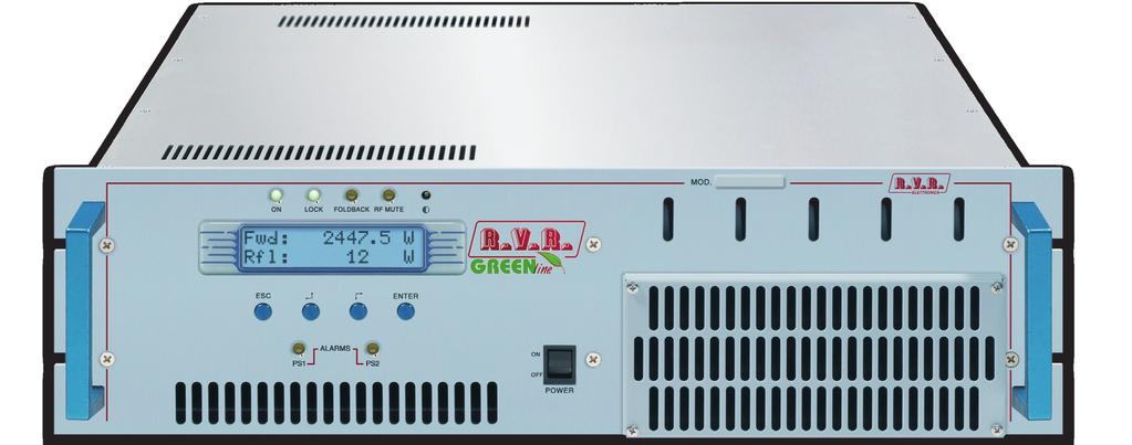
11 4.3 Frontal Panel Description Frontal Panel Description of [1] ON Green LED - Turns on when amplifier is powered on. [2] FAULT Red LED, lit on in presence of a fault that can not be resolved automatically. [3] FOLDBACK Yellow LED - Turns on when foldback current limiting (Automatic Gain Control) is intervened. [4] R.F. MUTE Yellow LED, lit on when the amplifier s power output is inhibited by an external interlock command. [5] CONTRAST Display contrast adjusting trimmer (on the top of the equipment). [6] ESC Press this button to exit a menu. [7] Navigation button used to browse menu system and edit parameters. [8] Navigation button used to browse menu system and edit parameters. [9] ENTER Press this button to confirm a modified parameter and open a menu. [10] DISPLAY Liquid Crystal Display. [11] POWER AC mains ON/OFF switch. [12] AIR FLOW Grid for the intake of the air flow of the forced ventilation. [13] ALARMS PS1 Yellow LED - Turns on when Power Supply unit is not fed either because PWR OFF was selected via software, or power is set to 0 W, or due to Power Supply malfunction (when this LED turns on, it causes the ALARM PS2 LED to come on as well, because the two LEDs are connected internally). [14] ALARMS PS2 Yellow LED, see item [13]. User Manual Rev /05/13 5 / 30
12 4.4 Rear Panel Description Rear Panel Description of [1] R.F. TEST -60dBc Output at -60 db refered to output power level, adapted to modulation monitoring. Do not use it for spectral analysis. [2] AIR FLOW Grid for the intake of the air flow of the forced ventilation. [3] REMOTE DB25 connector for telemetry of the machine. [4] MAINS Mains supply connectors, 230 V Hz. [5] FUSE1 Mains supply fuse. [6] R.F INPUT RF input connector, N-type. [7] R.F OUTPUT RF output connector, 7/8 EIA flange. [8] SERVICE DB9 connector for interconnection with other devices and for factory parameters programming (only for factory programming). [9] INTERLOCK OUT Interlock output BNC connector: to inhibit an external device, as an exciter. In case of fault, the inner connector is shorted to ground. [10] INTERLOCK IN Interlock input BNC connector: to inhibit the amplifier from an external device, like an exciter. [11] I 2 C DB9 connector for I 2 C bus networking. [12] FUSE2 Mains supply fuse. / 30 Rev /05/13 User Manual
13 4.5 Connectors Description Remote Type: Female DB25 1 N.C. 2 RF power amplifier voltage 3,9V x 50V 3 GND GND 4 Reflected Power 3.9V x 230W (depending on model) 5 Interlock 6 Set 4 7 GND GND 8 On command 9 Set 1 10 WAIT 11 Reset alarm 12 OFF 13 Interlock 14 N.C. 15 RF power amplifier current 3.9V x 108A (depending on model) 16 Forward power 3.9V x 2500W (depending on model) 17 FAULT 18 Set 3 19 Input power 3.9V x 31W (depending on model) 20 OFF command 21 GND GND 22 Set 2 23 LOC 24 +Vcc 25 ON I 2 C Bus Type: Male DB9 1 NC 2 SDA Serial DAta 3 SCL Serial CLock 4 NC 5 GND GND 6 NC 7 NC 8 NC 9 NC User Manual Rev /05/13 7 / 30
14 4.5.3 Service (for programming of factory parameters) Type: Female DB9 1 NC 2 TX_D 3 RX_D 4 Internally connected with 6 5 GND 6 Internally connected with 4 7 Internally connected with 8 8 Internally connected with 7 9 NC / 30 Rev /05/13 User Manual
15 5. Quick guide for installation and use This section provides a step-by-step description of equipment installation and configuration procedure. Follow these procedures closely upon first power-on and each time any change is made to general configuration, such as when a new transmission station is added or the equipment is replaced. Once the desired configuration has been set up, no more settings are required for normal operation; at each power-up (even after an accidental shutdown), the equipment defaults to the parameters set during the initial configuration procedure. The topics covered in this section are discussed at greater length in the next sections, with detailed descriptions of all hardware and firmware features and capabilities. Please see the relevant sections for additional details. IMPORTANT: When configuring and testing the transmitter in which the equipment is integrated, be sure to have the Final Test Table supplied with the equipment ready at hand throughout the whole procedure; the Final Test Table lists all operating parameters as set and tested at the factory. 5.1 Preparation Preliminary checks Unpack the amplifier and immediately inspect it for transport damage. Ensure that all connectors are in perfect condition. The main fuse can be accessed from the outside on the rear panel. Extract the fuse carrier with a screwdriver to check its integrity or for replacement, if necessary. The following fuses are used: Main Fuse (fig. 4.4 items [5] and [12]) Service power supply (internal 230 Vac (2x) 25A tipo 10x38 (1x) 3.15A tipo 5x20 Table 5.1: Fuse Provide for the following (applicable to operating tests and putting into service): Single phase mains power supply 230 VAC (±15%) for, with adequate earth connection. User Manual Rev /05/13 9 / 30
16 For operating tests only: dummy load with 50 Ohm impedance and adequate capacity (2500W for as a minimum). Connection cable kit including: Mains power cable. Coaxial cable with BNC connectors for interlock signal connection between exciter and amplifier. RF cable for output to load / antenna (50 Ohm coaxial cable with standard 7/8 connector) Connections Connect the output of a suitable FM exciter (for instance, PTX30LCD exciter available from R.V.R. Elettronica) to the RF input using a 50 Ohm coaxial cable with N -type connectors. To begin with, set exciter to minimum output power and switch if off. Connect the amplifier INTERLOCK OUT output to the matching INTERLOCK IN input fitted on all R.V.R. Elettronica exciters as standard; if your exciter is a different brand, identify an equivalent input. Connect the RF output to an adequately rated dummy load or to the antenna. The diagram of RF connection and control between the amplifier and its exciter and connection with the load, is represented in Figure 5.2. FigurE 5.1: connections with amplifier WARNING: Electric shock hazard! Never handle the RF output connector when the equipment is powered on and no load is connected. Injury or death may result. 10 / 30 Rev /05/13 User Manual
17 Ensure that the POWER switch on the front panel is set to OFF. Connect the mains power cable to the MAINS connector on the rear panel. Note : The mains must be equipped with adequate ground connection properly connected to the machine. This is a pre-requisite for ensuring operator safety and correct operation. WARNING: The power supply connector is a terminal board. Ensure the wire is not live before performing the connection. 5.2 First power-on and setup Follow this procedure upon first power-on and after making changes to the configuration of the transmitter in which th amplifier is integrated. Note : Standard factory settings are RF output power on (Pwr ON) and regulated output power set to lower limit (unless otherwise specified by customer) Pilot exciter setup Set up the pilot exciter so that the output power it delivers to a matched load equals the maximum input power indicated in the amplifier final test table, switch off the exciter and connect it to the amplifier. IMPORTANT: to obtain the maximum efficiency, place the excitation power to a 20W as minimum Exciter frequency setup Set the operating frequency in according to your needs, switch off the exciter and connect it to the amplifier Power-on When you have performed all of the connections described in the previous paragraph, power on the amplifier using the suitable power switch on the front panel. Also, switch on the pilot exciter Power check Ensure that the ON light turns on. Machine name should appear briefly on the display, quickly followed by forward and reflected power readings (figure menu 1). If RF output is disabled, these readings will be zero. User Manual Rev /05/13 11 / 30
18 5.2.5 How to enable Local mode and the RF output Check current mode setting and enable Local mode (if not already enabled) following menu path Fnc Loc Local (figure 5.2): if left disabled, the machine will not accept the next commands. Check current RF output setting and enable output (if not already enabled) following menu path Fnc Pwr ON (figure menu 4). Check output power level and set to maximum level (if not already set to maximum) from the Power Setup Menu, which you can call up by pressing these keys in the order: ESC (opens Default Menu) ENTER (hold down for 2 seconds) SET use key to set bar to maximum limit (figure menu 2) RF output power level control IMPORTANT: The amplifier incorporates Automatic Gain Control and output power is modulated based on the power level set by the user and actual operating conditions, such as temperature, reflected power and other parameters. Drive power must be kept steady at maximum output power capacity. Please read section 5.3 for more details of RF power modulation. Open the Power Setup Menu (figure menu 2) pressing the following keys in the order: ESC (opens Default Menu) ENTER (hold down for 2 seconds). Use the keys and in the SET menu to set amplifier output power; the setting bar at the side of SET provides a graphic indication of power setting; please consider that the forward power readout provided on the display (FWD: xxxx W) reflects actual output power reading, which may be lower than regulated power supply when Automatic Gain Control is running in power supply limitation mode (please read section 5.3 about RF power supply modulation for more details). Note : Output power can also be set in a Pwr OFF condition; in this condition, (Fwd) output power reading on the display will be 0 (zero), whereas the SET bar, which you can control using the keys, provides a graphic display of the amount of power that will be delivered the moment you switch back to Pwr On state Adjustment of setting in the piloting exciter Adjust the piloting exciter so that it delivers an output power, on adapted load, equal to the maximum input power of the amplifier, as shown in the Final Test Table. IMPORTANT: put the minimum excitation power at 20W to have the maximum efficiency. 12 / 30 Rev /05/13 User Manual
19 5.2.8 Adjustment of RF output power level control Open the Power setup menu (figure Menu 2), pressing the following keys in the order: ESC (opens Default Menu) ENTER (hold down for 2 seconds).. Use the keys and in the SET menu to set amplifier output power. For combined amplifiers, increase the power alternately on both. This is to avoid high values of unbalanced power (Rej Pwr) on the combiner. Note: recheck the output power of transmitter system after ten minutes and, if necessary, repeat the operations described above to adjust it. A decline in the value of equipment is possible due to heat shock or special working conditions Changing the Power Good alarm threshold Change Forward Power Good alarm setting PgD from the Fnc menu as desired (factory setting is 50%) Setting equipment I 2 C address Change the IIC address in the MIX (Miscellaneous) menu as desired (factory setting is 01) How to enable Remote mode If you wish to use the telemetry control feature, enable Remote control in the Fnc menu (see section for details). Note : In the Remote mode, all local push-button controls except Remote/Local for switching back to Local mode) are disabled. Operating parameter readings are available. 5.3 Operation NOTE: For better clarity, only the typical screens of are reported below. 1) Power on the amplifier and ensure that the ON light turns on. Machine name should appear briefly on the display, quickly followed by forward and reflected power readings (Menu 1), provided that the amplifier is delivering output power. User Manual Rev /05/13 13 / 30
20 Menu 1 1b) To modify power level setting, hold down the ENTER button until opening the power setup menu. The edit screen will look like this: Menu 2 Next to SET indication, a bar provides a graphic display of preset output power. The filled portion of the bar is proportional to set power level. Example 100% output power Full bar 2500W in output (mod.pj2500light) 50% output power Half bar 1250W in output (mod.) 25% output power 1/4 bar 625W in output (mod.) The bottom line provides instantaneous power reading (2400W in this instance); press button to increase level, press to decrease it. When you have achieved the desired level, press ENTER to confirm and exit the default menu. Please note that the setting is stored automatically; in other words, if you press ESC or do not press any keys before the preset time times out, the latest power level set will be retained. NOTE: This feature prevents the machine from delivering maximum power as soon as output is enabled from menu 4, or in the event the machine is already set to ON and energised. 2) Ensure that machine is not in a locked-out state. Press the ESC key (chap. 6.1) to call up the selection screen (Menu 3). Highlight Fnc and press ENTER to confirm and access the appropriate menu (menu 4). If LOC is set to REMOTE (machine remote control), move cursor to LOC and press ENTER; label will change to LOCAL, i.e. local control operation mode. 14 / 30 Rev /05/13 User Manual
21 In the same menu, ensure that power limiting is disabled: if PWR is set to OFF, i.e. power output is disabled, move cursor to PWR. Press ENTER and label will switch to ON, i.e. power output enabled. Press ESC twice to go back to the default menu (menu 1). 3) Fine tune power setting from menu 2 (see description of item 1b) until achieving the desired value. WARNING: Machine is capable of delivering more than rated output power (2500 W); however, never exceed the specified power rating. NOTE: Exciter drive power setting should never exceed 30W, or it will trigger an Overdrive Alarm. NOTE: If power is set to 0 W in the edit mode, the INTERLOCK OUT contact trips and external exciter power is immediately inhibited. Next, you can review all operating parameters of the machine through the management firmware. Normally, the machine can run unattended. Any alarm condition is handled automatically by the safety system or is signalled by the LED indicators on the panel or by display messages. NOTE: Standard factory settings are: output power set to upper limit (unless otherwise specified by customer) and OFF. 5.4 Management Firmware The machine features an LCD with two lines by 16 characters that displays a set of menus. Figure 5.2 below provides an overview of machine menus. The symbols listed below appear in the left portion of the display as appropriate: (Cursor) - Highlights selected (i.e. accessible) menu. (Filled arrow) - Editable parameter marker. This symbol appears in menus that take up more than two lines to aid browsing. (Three empty arrows) - Parameter is being edited. (Empty arrow) - Current line marker; the parameter in this line cannot be edited. This symbol appears in menus that take up more than two lines to aid browsing. User Manual Rev /05/13 15 / 30
22 Menù 1 Menù 2 Menù Predefinito Menù Regolazione Potenza Menù 3 Menù di Selezione Menù 4 Menu Funzione Menù 5 Menu Potenza Menù Menu P.A. Menù 7 Menu Allarmi Menù Menu Varie Menù 9 Menu Versione Figure 5.2 When the display is off, touching any key will turn on backlighting. When the display is on, pressing the ESC button from the default menu (menu 1) calls up the selection screen (menu 3), which gives access to all other menus: Menu 3 To gain access to a submenu, select menu name (name is highlighted by cursor) using button or and press the ENTER button. Press ESC again to return to the default menu (menu 1) Operation Menu (Fnc) In this menu, you can set power output On/Off, toggle between Local or Remote control mode and set the Forward Power Good (PgD) threshold rate. 16 / 30 Rev /05/13 User Manual
23 To edit an item, highlight the appropriate line using the UP and DOWN buttons and then press and hold the ENTER button until the command is accepted. This way, Pwr setting is toggled between On and Off and Mod setting is toggled between x1 and x10. To edit the Power Good rate, simply select item PgD and edit its value using buttons and ; finally, press ENTER to confirm. Pwr Loc PgD Menu 4 Enables (ON) or disables (OFF) amplifier power output. Modifies machine operation. In the LOCAL mode, the machine can read and modify its operating parameters through the navigation keys and the management firmware, whereas all other sources are locked out. In the REMOTE mode, the machine can only read its operating parameters; parameters are modified based on the commands received from other connected telemetry systems. Modifies Power Good (forward power) threshold. The Power Good rate is a percent of machine rated power (2500W for PJ25000LCD), not of forward output power. This means that this threshold set at 50% will give 1250 W regardless of set power level. The Power Good feature enables output power control and reporting. When output power drops below set Power Good threshold, the machine changes the state of pin on the DB25 Remote connector located on the rear panel Power Menu (Pwr) This screen holds all readings related to machine output power: Fwd Rfl Inp Forward power reading. Reflected power reading. Input power reading. Menu 5 Note that these are readings, rather than settings, and cannot be edited (note the empty arrow). To change power setting, go to the default menu (menu 1) as outlined earlier. User Manual Rev /05/13 17 / 30
24 5.4.3 Power Amplifier (P.A) Menu This screen is made up of four lines that can be scrolled using the buttons, shows the readings relating to final power stage: and Menu 6 Note that these are readings, rather than settings, and cannot be edited (note the empty arrow). VPA IPA Eff Tmp Alarm Menu (Alm) Voltage supplied to amplifier module. Current absorbed to amplifier module. Efficiency based on ratio of forward power to amplifier module power in percent ( FWD PWR/(Vpa x Ipa) % ). Machine internal temperature. This menu shows any alarm conditions occurring during machine operation. Alarm thresholds are preset at the factory. FWD RFL INP Menu 7 Conteggio delle situazioni di allarme dovuti a potenza diretta. Conteggio delle situazioni di allarme dovuti a potenza riflessa. Conteggio delle situazioni di allarme dovuti a potenza in ingresso. 18 / 30 Rev /05/13 User Manual
25 Reset Alm Reset sulla numerazione delle situazioni di allarme. Alarm conditions are numbered from 1 to 10 and reflect the following situations: forward output power too high, reflected output power too high and input power too high. Alarm monitoring cycle is as follows: when an alarm condition is detected, alarm counter increases by 1 unit, machine goes into lock-out state and the display shows the cause for the stop (chap ). After 15 seconds, the machine attempts to re-start; if a new alarm condition is detected, cycle is repeated over and over again up to 10 times maximum. If machine re-starts successfully, all alarm counters are reset after 30 minutes regular operation. After 10 alarm conditions triggered by the same cause, the machine goes into fault lock-out mode, a lock-out mode warning appears on the display and the FAULT/LOCK LED turns on. After the alarm condition has been rectified, the counter can be reset by highlighting Reset Alm and holding down the ENTER key for some time Alarms e Faults There are three types of alarms that can cause a machine lock-out and trigger a FAULT/LOCK indication. When any one of the three alarm thresholds is exceeded, the system will automatically switch to the warning screen (even though the user is browsing system menus) and the following messages are displayed: 1. Over Forward Power Forward power threshold exceeded. 2. Over Reflected Power Alarm 1 Reflected power threshold exceeded. Alarm 2 User Manual Rev /05/13 19 / 30
26 3. Over Input Power Input power threshold exceeded. Alarm 3 Monitoring cycle is as follows: An alarm condition occurs; Alarm is displayed and device is locked out for 15 sec.; Operating conditions are restored; Verification. Upon reaching the 10 cycle limit, a FAULT/LOCK indication is triggered and the device goes into lock-out mode; the appropriate LED turns on (figure 6.1) and this screen is displayed: I. Over Forward Power Forward power alarm display. II. Over Reflected Power Stop 1 Reflected power alarm display. III. Over Input Power Stop 2 Input power alarm display. Stop 3 20 / 30 Rev /05/13 User Manual
27 Once the machine goes into FAULT mode, it will no longer attempt to re-start; choose the appropriate reset procedure according to current machine setting: Machine set to LOCAL control mode - press Reset Alm in the alarm menu (menu 7) or power off and back on again using the POWER switch. Machine set to REMOTE control mode - power off and back on again sending the appropriate command via the DB25 connector (pin [8] and [20]). There is a fourth alarm that does not trigger a FAULT condition, but allows some time until correct operating conditions are restored. When the temperature alarm threshold is exceed (about 85 C), the following screen appears: 4. Over Temperature Temperature power threshold exceeded. Alarm Miscellaneous Menu (Mix) This menu lets you set machine address in an I 2 C bus serial connection: IIC Menu 8 I 2 C address setting. The I 2 C network address becomes significant when the exciter is connected in an RVR transmission system that uses this protocol. Do not change it unless strictly required Version Menu (Vrs) This screen holds machine version/release information: Menu 9 User Manual Rev /05/13 21 / 30
28 Note that these are readings, rather than settings, and cannot be edited (note the empty arrow). Rel Dat Tab Firmware release information. Release date. Shows table loaded in the memory. 22 / 30 Rev /05/13 User Manual

29 6. Identification and Access to the Modules The is made up of various modules linked to each other through connectors so as to make maintenance and any required module replacement easier. 6.1 Upper view The figure below shows the upper view of the machine with the various components pointed out. [1] Bias Board [2] Pass Through Board [3] LPF Board [4] Panel Board [5] Impeller FAN1 [6] Power supply module [7] Power Factor module [8] Surge Protection Board [9] Telemetry Board [10] Impeller FAN2 [11] PWR Input Measure Board [12] Splitter Board [13] RF Amplifier Board [14] Combiner Board [15] Fuse Board figure 6.1 User Manual Rev /05/13 23 / 30

30 6.2 Lower view The figure below shows the upper view of the machine with the various components pointed out. [1] LED PS Board [2] Interface Board [3] Power Supply 24V 3A [4] Telemetry Board figure / 30 Rev /05/13 User Manual
31 7. Working Principles The figures below provide an overview of PJ1600LIGHT (fig. 7.1) and PJ2000LIGHT (fig. 7.2) modules and connections. R.F. INPUT PWR INPUT MEASURE R.F. 4 X R.F. 4 X R.F. R.F. SPLITTER RF MODULES COMBINER LPF + DIRECT. COUPL. R.F. OUTPUT 4 X VPA (50VDC) BIAS FUSE BOARD FWD PWR RFL PWR 4 X VPA (50VDC) BIAS INTERFACE PANEL VOLTAGE REG. 4 X 50VDC PS ALARM MAINS SURGE PROT. PFC (RECTIFIER) DC POWER SUPPLY LED CARD TELEMETRY Figure 7.1 Following is a brief description of the different module functions; all diagrams and board layout diagrams are included in the Technical Schedule Vol Panel Board The panel board accommodates the microcontroller that runs the machine control software and all user interface elements (display, LED s, keys, ). This board is interfaced with other machine modules via flat cables and provides for power supply, control signals and measurement distribution. 7.2 Interface Board This board performs the following tasks: It uses AC voltage to generate and distribute service power supply over the panel board; It controls and provides interfacing of the mains surge protection module; It controls and provides interfacing of the power amplifier supply module; It processes and provides interfacing of the control signals to/from the Bias Board; It processes and provides interfacing of the control signals to/from the Panel Board. User Manual Rev /05/13 25 / 30
32 It feeds and operates the cooling fans; It feeds and controls the LED indicator board. 7.3 Telemetry Board This board provides an I/O interface for the CPU with the outside environment. All available machine input and output signals are brought to the REMOTE DB25 connector. Also mounted on this board is the INTERLOCK IN BNC connector which can disable device power output. When the central pin is closed to ground, output power is limited to zero until ground connection is removed. 7.4 Mains power supply pulse protection This module is enclosed in a sealed metal case; it features two externally mounted mains fuses and accommodates a bank of surge arresters that protect the machine from any surge events in the power mains. Mains voltage is brought from this module to the main Power switch on the front panel, which relays it to the service transformer TR1. Inside the surge protection module, a suitable 24VDC relay controlled via the interface board isolates (single line) mains voltage to be fed to the power amplifier power supply unit (PFC module). This way, mains power supply to PFC is enabled when these requirements are met: POWER switch on front panel set to ON; No alarm or fault events present; Power output enabled (set to ON) in FNC operation menu; RF output power set to over 0W using the edit mode. 7.5 PWR Input Measure Board This card makes two check and measure functions: - Input power measure, measure sended to interface card that supplies to send machine in protection mode in case of input power excess. - Temperature measure. 26 / 30 Rev /05/13 User Manual
33 7.6 Power supply The PJ25000LCD power supply sections is made up of three basic sections: 1. Surge Protection: Surge Protection board protects machine from eventual unexpected variations of the mains voltage. 2. Service: This section contains elements that do not regard directly the power supply, they are:: - Service transformer - Power switch - Service fuse 2. Power supply: various units supplies an adapted supply to RF power amplifier modules. The units that compose power supply are rectifiers (PFC or traditionals) and switching supply. Machine is available in different configuration for voltage rectify Mains power supply pulse protection This module is enclosed in a sealed metal case; it features two externally mounted mains fuses and accommodates a bank of surge arresters that protect the machine from any surge events in the power mains. Mains voltage is brought from this module to the main Power switch on the front panel, which relays it to the service transformer TR1. Inside the surge protection module, a suitable 24VDC relay controlled via the interface board isolates (single line) mains voltage to be fed to the power amplifier power supply unit (PFC module). This way, mains power supply to PFC is enabled when these requirements are met: POWER switch on front panel set to ON; No alarm or fault events present; Power output enabled (set to ON) in FNC operation menu; RF output power set to over 0W using the edit mode PFC Unit PFC unit is a rectifier that modulates absorbed current so that the wave shape is sinusoide, having so 99% power factor. PFC can work with input mains voltage of 230 V. In PFC output there are 350 V of rectified voltage. User Manual Rev /05/13 27 / 30
34 7.6.3 Power Supply There is a power supply switching mode of 50 V 60 A, that have an input voltage check. Output voltage is set from microprocessor in function of RF power required. The power supply units have a balance current circuit. 7.7 Power Amplifier RF power amplifier section is made with four power amplifier modules combined through a Wilkinson splitter and a Wilkinson combiner in strip-line technology. The splitter is used to divide input power from PWR Input Measure card and to supply a part of it to every RF module. The combiner is used to combine output power from every RF module so as to have total power amplifier. Splitter, amplifier and combiner are plans so that powers generated from the amplifiers add its in phase, diminishing the loss of balance and therefore the dissipation of useful power. All RF section is placed on a fin that supplies to the cooling through forced ventilation. Every RF module supplies 850 watts ( four in model) and is supplied from own switching supply. The active device used in the amplifier modules is a Mosfet (MRF6VP11KH for model). 7.8 LPF Card This card is a low-pass filter and its function is to suppress the harmonic components generated by the amplifier below the levels required by regulations. Moreover, in the end of filter, there is a directional coupler, its function is the measurement of the forward and reflected output power. On this card there is an RF sample at -60 db compared with the output and it is available on a BNC connector. This sample is useful for checking the characteristics of the carrier, but not of the higher order harmonics. 28 / 30 Rev /05/13 User Manual
35 7.9 BIAS Card Main function, of this card, is to check and to correct the polarization voltage (BIAS) of Mosfet in RF amplifier section. Moreover it supplies the measure of the absorbed current as sum of the absorbed currents from every module and it contains a circuit for the signalling of the breakdowns in the Power Supply. Without alarm condition, Bias voltage is regulated only in function of output power set up, with a feedback mechanism based on the reading of the effectively distributed power (AGC). Bias voltage is also influenced from other factors like: - Excess of reflected voltage - External AGC signals (Ext. AGC FWD, Ext. AGC RFL,...) - Excess of temperature - Excess of absorbed current from a RF module. User Manual Rev /05/13 29 / 30
36 This page was intentionally left blank 30 / 30 Rev /05/13 User Manual
37
38
39

40 R.V.R Elettronica S.p.A. Via del Fonditore, 2 / 2c Zona Industriale Roveri Bologna Italy Phone: Fax: info@rvr.it web: ISO 9001:2000 certified since 2000 The RVR Logo, and others referenced RVR products and services are trademarks of RVR Elettronica S.p.A. in Italy, other countries or both. RVR 1998 all rights reserved. All other trademarks, trade names or logos used are property of their respective owners.
PWRMETER-D2. User Manual Volume 1. Manufactured by
 User Manual Volume 1 Manufactured by Italy File Name: 03_PWRMETER-D2_ING_1.3.indd Version: 1.3 Date: 15/05/2014 Revision History Date Version Reason Editor 24/10/2008 1.0 First Edition J. H. Berti 09/01/2009
PJ500C-LCD, PJ700C-LCD & PJ1000-LIGHT
 PJ500C-LCD, PJ700C-LCD & PJ1000-LIGHT Volume 1 Manufactured by Italy File Name: 03_PJ500C-LCD_PJ700C-LCD&PJ1000light_ING_1.0.indd Version: 1.0 Date: 24/06/2008 Document History Date Version Reason Editor
/TLC. Additional Manual for TEX-LCD series and TEX-LIGHT series. Manufactured by
 Additional Manual for TEX-LCD series and TEX-LIGHT series Manufactured by Italy File Name: 03_TLC_ING_1.0.indd Version: 1.0 Date: 01/02/2008 Revision History Date Version Reason Editor 01/02/2008 1.0 Prima
TCPIPINT-SCMN USER MANUAL. Manufactured by R.V.R ELETTRONICA S.p.A. Italy
 USER MANUAL Manufactured by R.V.R S.p.A. Italy File Name: _ING_1.0.indb Version: 1.0 Date: 15/04/2016 Revision History Date Version Reason Editor 15/04/2016 1.0 First edition J. H. Berti - User Manual
BS 287 DUAL CHANNEL POWER SUPPLY. User Manual. January 2017 V1.0
 BS 287 DUAL CHANNEL POWER SUPPLY User Manual January 2017 V1.0 Table of contents 1.0 SAFETY INSTRUCTIONS... 3 2.0 GENERAL DESCRIPTION PS 289... 4 3.0 MECHANICAL INSTALLATION... 5 4.0 MAINS POWER & SAFETY
BS 181 SINGLE CHANNEL POWER SUPPLY USER MANUAL
 BS 181 SINGLE CHANNEL POWER SUPPLY USER MANUAL Issue 2011 ASL Intercom BV DESIGNED & MANUFACTURED BY: ASL Intercom B.V. Zonnebaan 42 3542 EG Utrecht The Netherlands Tel: +31 (0)30 2411901 Fax: +31 (0)30
MODEL 805 USER MANUAL
 MODEL 805 USER MANUAL All Rights Reserved Page 1 of 12 UNPACKING & INSPECTION Save all packing materials they are required for returns and warranty service. Inspect the 805 and packing materials for any
OWNER S MANUAL CD-2 V 1.3
 OWNER S MANUAL CD-2 V 1.3 2 TABLE OF CONTENTS WARNINGS... 3 ACCESSORIES... 4 REMOTE CONTROL... 5 FRONT PANEL... 6 REAR PANEL... 7 MENU SYSTEM... 8 NOTES OF IMPORTANCE... 10 CONNECTORS... 11 TECHNICAL SPECIFICATIONS...
Cantata m100 Amplifier
 Cantata m100 Amplifier Getting Started Guide www.resolutionaudio.com +1.415.553.4100 Safety Information CAUTION RISK OF ELECTRICAL SHOCK DO NOT OPEN CAUTION: TO REDUCE THE RISK OF ELECTRICAL SHOCK, DO
Audio Zone Amplifier 2 x 20 watts Installation Guide
 2 x 20 watts 500216 MuxLab Inc. 2015 94-000805-A / SE-000805-A SAFETY PRECAUTIONS To insure the best from the product, please read all instructions carefully before using the device. Save this manual for
AUD-220 Installation Guide
 AUD-220 Installation Guide STEREO MONO BRIDGE IR RS232 TX RX MIC 48V LINE L R MIC 1 2 INPUTS 24V DC 1 x 40W @ 8Ω 2 x 20W @ 4Ω LOOP OUTPUTS The Intelix AUD-220 is a 2x20 watt Class D amplifier with 8Ω speaker
PS8 - II. Professional Power Sequencer. User s Manual
 PS8 - II Professional Power Sequencer User s Manual IMPORTANT SAFETY INSTRUCTIONS READ FIRST This symbol, whenever it appears, alerts you to the presence of uninsulated dangerous voltage inside the enclosure.
POWER Shiloh Road Alpharetta, Georgia (770) FAX (770) Toll Free
 FAX (770) Toll Free") Instruction Manual Model 1582-10M Protection Switch January 2009 Rev O ALARMS MENU OUTPUT = CH1 AUTO POWER 1 2 MODEL 1582 SWITCH CROSS TECHNOLOGIES INC. CH1 CH2 REMOTE EXECUTE Data, drawings, and other
Instruction Manual Model 1582-10M Protection Switch January 2009 Rev O ALARMS MENU OUTPUT = CH1 AUTO POWER 1 2 MODEL 1582 SWITCH CROSS TECHNOLOGIES INC. CH1 CH2 REMOTE EXECUTE Data, drawings, and other
Model 7705 Control Module
 www.keithley.com Model 7705 Control Module User s Guide PA-696 Rev. D / October 2006 A G R E A T E R M E A S U R E O F C O N F I D E N C E Safety Precautions The following safety precautions should be
It s Under Control. Installation and Operation Guide CPB-1. Control Port Connecting Block V 1.1
 Installation and Operation Guide 70-210043-17 V 1.1 Copyright 2008 Remote Technologies Incorporated All rights reserved. 2 DECLARATIONS 117 612 914 DECLARATION OF CONFORMITY (DOC) The Declaration of Conformity
PS 289 DUAL CHANNEL POWER SUPPLY USER MANUAL
 PS 289 DUAL CHANNEL POWER SUPPLY USER MANUAL August 2016 This product is designed and manufactured by: ASL Intercom B.V. Zonnebaan 42 3542 EG Utrecht The Netherlands Phone: +31 (0)30 2411901 Fax: + 31
AUD-340 Installation Guide
 F0123456789ABC DE AUD-340 Installation Guide INPUTS CONTROL OUTPUT 24V DC 48V LINE 2 AUDIO IR RS232 COM 70V 100V 1 3 DIGITAL L R AUDIO 2.5A MAX TX RX 1 2 3 INPUT SELECT LINE BASS TREBLE MUTE 1 Safety Precautions
EPS Power Supply
 EPS - 600 Power Supply Installation and Operation Manual Version 1.0 *This instrument is intended for laboratory use only Index A. Important Notice ----------------------------------------------------------------
Kramer Electronics, Ltd.
 Kramer Electronics, Ltd. Preliminary USER MANUAL Model: VM-1120 1:10 Balanced Stereo Audio Distributor Contents Contents 1 Introduction 1 2 Getting Started 1 2.1 Quick Start 2 3 Overview 3 4 Your Balanced
T L Audio INDIGO SERIES. User Manual PA-2001 VALVE PRE-AMPLIFIER. Tony Larking Professional Sales Limited, Letchworth, England.
 T L Audio INDIGO SERIES User Manual PA-2001 VALVE PRE-AMPLIFIER Tony Larking Professional Sales Limited, Letchworth, England. Tel: 01462 490600. International +44 1462 490600. Fax: 01462 490700. International
ANT CNTR DC ALRM LNB RX DC ALRM +18V OFF
 Instruction Manual Model 2082-1972 Power Supply July 2012, Rev. B MODEL 2082 POWER SUPPLY CROSS TECHNOLOGIES INC. PRIMARY PWR AC BUC +48V AUX BUC TX SELECT 48V +18V/48V LNB RX +18V ANT CNTR +29V AC 18V
OPERATIONS MANUAL. n.form I/O Expander (RACK MOUNT) Document Number: Rev B
 Document Number: Rev B") OPERATIONS MANUAL n.form I/O Expander (RACK MOUNT) Document Number: 200-0009 Rev B table of contents INTRODUCTION FEATURES & CAPABILITIES 1 WIRING General I/O Configuring The System Using The System 4
OPERATIONS MANUAL n.form I/O Expander (RACK MOUNT) Document Number: 200-0009 Rev B table of contents INTRODUCTION FEATURES & CAPABILITIES 1 WIRING General I/O Configuring The System Using The System 4
BS 181 SINGLE CHANNEL POWER SUPPLY USER MANUAL
 BS 181 SINGLE CHANNEL POWER SUPPLY USER MANUAL August 2016 This product is designed and manufactured by: ASL Intercom B.V. Zonnebaan 42 3542 EG Utrecht The Netherlands Phone: +31 (0)30 2411901 Fax: +31
INSTRUCTION MANUAL. Card Revision: Software 2.1 Card Revision: Hardware B(2.0) DOCUMENT SES-KS-2422-E REV. 3
 DOCUMENT SES-KS-2422-E REV. 3") 2422 DIGITAL OUTPUT CARD 16 CHANNELS INSTRUCTION MANUAL Card Revision: Software 2.1 Card Revision: Hardware B(2.0) DOCUMENT SES-KS-2422-E REV. 3 2422 DIGITAL OUTPUTS CARD 16 CHANNELS SES-ASA ENGINEERING
2422 DIGITAL OUTPUT CARD 16 CHANNELS INSTRUCTION MANUAL Card Revision: Software 2.1 Card Revision: Hardware B(2.0) DOCUMENT SES-KS-2422-E REV. 3 2422 DIGITAL OUTPUTS CARD 16 CHANNELS SES-ASA ENGINEERING
INDOOR/OUTDOOR SPEAKER WITH BLUETOOTH WIRELESS TECHNOLOGY PART NUMBER PA360 EXPERIENCE 360 OF SOUND. pulseaudio1.com vanco1.com
 INDOOR/OUTDOOR SPEAKER WITH BLUETOOTH WIRELESS TECHNOLOGY PART NUMBER PA360 EXPERIENCE 360 OF SOUND pulseaudio1.com vanco1.com 800.626.6445 DEAR CUSTOMER Thank you for purchasing this product. For optimum
Owner s Manual. Isolate. Restore. Inspire! Power Conditioners Audio / Video Power Isolation Units Rack Mount / Consumer Series
 Owner s Manual 19 Pro Series Rack Mount (RK) Faceplate Isolate. 17 Consumer Series (C) Faceplate Available in Black (B) and Silver (S) Colours Restore. Power Conditioners Audio / Video Power Isolation
Antenna Distributor ORDERCODE D1444
 Antenna Distributor ORDERCODE D1444 Congratulations! You have bought a great, innovative product from DAP Audio. The DAP Audio TAS series bring excitement to any venue. Whether you want simple plug-&-play
INSTRUCTION MANUAL DISTRIBUTION UNIT. Please read this manual thoroughly before use, and keep it handy for future reference.
 INSTRUCTION MANUAL DISTRIBUTION UNIT Please read this manual thoroughly before use, and keep it handy for future reference. ISSUE 1 May 2006 LIMITATION OF LIABILITY THE INFORMATION IN THIS PUBLICATION
Installation Guide. QBox-V6. Standalone/Spare V6 SDI QBox. Standalone/Spare V6 SDI QBox. Part No. A
 Installation Guide Standalone/Spare V6 SDI QBox QBox-V6 Standalone/Spare V6 SDI QBox Part No. A9009-0004 EN www.autocue.com Copyright 2017 All rights reserved. Original Instructions: English All rights
User Manual - KVM Rear Kit Version
 dedicated KVM switch and rackmount screen technology User Manual - KVM Rear Kit Version for LCD Console Drawer PS/2 DB-15 KVM - 801 back Designed and manufactured by Austin Hughes 751 Legal Information
PRE116/126. User Manual.
 PRE116/126 User Manual www.audac.eu ADDITIONAL INFORMATION This manual is put together with much care, and is as complete as could be on the publication date. However, updates on the specifications, functionality
JuiceRack & JuiceBlock 500 series Power Supplies. Operating Manual V 1.1
 JuiceRack & JuiceBlock 500 series Power Supplies Operating Manual V 1.1 Contents 1 Safety instructions... 3 2 Foreword... 4 2.1 Important Notes:... 4 3 Introduction... 5 3.1 Setup... 5 3.2 Mains Voltage...
TOT Series Manual. North American CE and UK Models. CE Models. UK Models. North American Models
 TOT Series Manual North American CE and UK Models CE Models UK Models North American Models Table of Content 1. Important Safety Instructions 2. Description Shipping Carton & Packing Material Placement
ATS-16 HV USER MANUAL. Automatic Transfer Switch 16A / 230Vac V090318
 ATS-16 HV Automatic Transfer Switch 16A / 230Vac USER MANUAL V090318 SAFETY Intended use The ATS-16 HV device serves as a power source selector to provide improved power supply for connected loads. ATS-16
RE-82 RACK MOUNT DIMMER OWNERS MANUAL. 8 X 2400Watts. Revision /29/2007
 RE-82 RACK MOUNT DIMMER 8 X 2400Watts OWNERS MANUAL Revision 2.4 11/29/2007 Page 2 of 8 RE-82 CONTROL PANEL DESCRIPTION The RE-82 is an 8 channel dimmer with a maximum capacity of 2,400 watts per channel
HDMI 1x4 SPLITTER. Ultra Slim Design Part Number: EVSLIM14 HDMI 1X4 ULTRA SLIM SPLITTER
 HDMI 1x4 SPLITTER Ultra Slim Design Part Number: EVSLIM14 HDMI 14 ULTRA SLIM SPLITTER www.vanco1.com 800.626.6445 DEAR CUSTOMER Thank you for purchasing this product. For optimum performance and safety,
MS-SL12-RD. 17-Outlet LCD Display Power Strip 20Amp INSTRUCTION MANUAL
 MS-SL12-RD 17-Outlet LCD Display Power Strip 20Amp INSTRUCTION MANUAL 122 Rose Ln., Suite 303, Frisco, Texas 75034 TOLL FREE: 1-877-ANEUTRON TOLL: (469) 362-9228 Email: sales@a-neutronics.com A-Neutronics.com
T L Audio INDIGO SERIES. User Manual C-2021 VALVE COMPRESSOR. Tony Larking Professional Sales Limited, Letchworth, England.
 T L Audio INDIGO SERIES User Manual C-2021 VALVE COMPRESSOR Tony Larking Professional Sales Limited, Letchworth, England. Tel: 01462 490600. International +44 1462 490600. Fax: 01462 490700. International
Emerson Network Power provides customers with technical support. Users may contact the nearest Emerson local sales office or service center.
 Liebert PSA iton User Manual Version: V2.8 Revision date: November 14, 2005 Emerson Network Power provides customers with technical support. Users may contact the nearest Emerson local sales office or
Electronic Temperature Controller. Instruction Manual Version
 Electronic Temperature Controller 701 Instruction Manual Version 1.00.01 Dear Customer, we have made up this operating manual in such a way that all necessary information about the product can be found
S66 Series Electronic Fan Speed Control
 FANs 121, 125, 1628.3 Product/Technical Bulletin S66 Issue Date 0918 S66 Series Electronic Fan Speed Control The S66 Series Electronic Fan Speed Control is designed to modulate the speed of single-phase,
2 CHANNEL, CLASS D AMPLIFIERS PA2X25 PA2X60 PA2X125 PA2X150. pulseaudio1.com vanco1.com
 2 CHANNEL, CLASS D AMPLIFIERS PA2X25 PA2X60 PA2X125 PA2X150 pulseaudio1.com vanco1.com 800.626.6445 DEAR CUSTOMER Thank you for purchasing this product. For optimum performance and safety, please read
USERS GUIDE ASP-18H-4K. HDMI 4K2K 1x8 Splitter with EDID Management. Manual Number:
 USERS GUIDE ASP-18H-4K HDMI 4K2K 1x8 Splitter with EDID Management i Manual Number: 141110 SAFETY INSTRUCTIONS Please review the following safety precautions. If this is the first time using this model,
TOT Series Manual. North American and International Models - without optional faceplate. Receptacle Panel of International Models, CE model shown
 TOT Series Manual North American and International Models - without optional faceplate Receptacle Panel of International Models, CE model shown North American Models Table of Content 1. Important Safety
OPR Power Series AC to DC POWER SUPPLY SERIES WITH REMOTE MANAGEMENT AND ALARM SYSTEMS. Model Nos. OPR065-48S / OPR065-48R. Manual
 OPR Power Series AC to DC POWER SUPPLY SERIES WITH REMOTE MANAGEMENT AND ALARM SYSTEMS Model Nos. OPR065-48S / OPR065-48R Manual Revision F July 2009 Optimal Power Supplies LLC www.optimal-power.com i
Kramer Electronics, Ltd. USER MANUAL. Model: VM-50AN. 1:5 Audio Distributor
 Kramer Electronics, Ltd. USER MANUAL Model: VM-50AN 1:5 Audio Distributor Contents Contents 1 Introduction 1 2 Getting Started 1 2.1 Quick Start 1 3 Overview 3 4 Your Audio VM-50AN 1:5 Distributor 4 5
Operation Manual. Concorde 600 Power Supply. *This instrument is intended for laboratory use only.
 Concorde 600 Power Supply Operation Manual Cat.no. R10-1001011 *This instrument is intended for laboratory use only http://www.recenttec.com E-mail : support@recenttec.com Version 1.1 Packing List x 1
USERS GUIDE MCX-STH. 3G SDI to HDMI Converter. Manual Number:
 USERS GUIDE MCX-STH 3G SDI to HDMI Converter i Manual Number: 151226 SAFETY INSTRUCTIONS Please review the following safety precautions. If this is the first time using this model, then read this manual
OPERATOR MANUAL OSD461A/OSD463A AUDIO FIBER OPTIC TRANSMISSION SYSTEM
 OPERATOR MANUAL OSD461A/OSD463A AUDIO FIBER OPTIC TRANSMISSION SYSTEM OSD461A/OSD463A AUDIO FIBER OPTIC TRANSMISSION SYSTEM Document No. 101052 Rev. 01 PAGE 2 INDEX 1 1 TECHNICAL SUMMARY... 4 1.1 BRIEF
Prisma II Platform. Optoelectronics
 Optoelectronics Prisma II Platform Description In optical transmission systems, the network platform forms the foundation of the product family. The Prisma II platform provides network operators with the
TVA2.1 2-Channel Digital Amplifier Installation Manual
 TVA2.1 2-Channel Digital Amplifier Installation Manual SAFETY INSTRUCTIONS WARNING: TO REDUCE THE RISK OF FIRE OR ELECTRIC SHOCK, DO NOT EXPOSE THIS APPLIANCE TO RAIN OR MOISTURE. CAUTION: TO REDUCE THE
Kramer Electronics, Ltd. USER MANUAL
 Kramer Electronics, Ltd. USER MANUAL Models: VP-200NK, 1:2 High Resolution XGA DA VP-300NK, 1:3 High Resolution XGA DA VP-400NK, 1:4 High Resolution XGA DA Contents Contents 1 Introduction 1 2 Getting
EOS-6000 Series Optical A/B Switch User Manual DC Version
 EOS-6000 Series Optical A/B Switch User Manual DC Version For more information on this and other products: Contact Sales at EMCORE 626-293-3400, or visit www.emcore.com. Table of Contents Table of Contents...2
Innovative Circuit Technology Ltd.
 Innovative Circuit Technology Ltd. Pro Series DC Power Supply INSTRUCTION MANUAL 855-343-001 Models: ICT690-12S/ICT690-12SB ICT690-24S/ICT690-24SB ICT690-48S/ICT690-48SB ICT1190-12S/ICT1190-12SB ICT1190-24S/ICT1190-24SB
Neets Switching Relay - 2. Installation manual
 Neets Switching Relay - 2 Installation manual Foreword The purpose of this document is to describe how to install and configure Neets Switching Relay 2 with build-in power supply. COPYRIGHT - All information
PS 680 SIX CHANNEL POWER SUPPLY WITH AUX MATRIX USER MANUAL
 PS 680 SIX CHANNEL POWER SUPPLY WITH AUX MATRIX USER MANUAL Issue 2010 ASL Intercom BV DESIGNED AND MANUFACTURED BY: ASL INTERCOM B.V. ZONNEBAAN 42 3542 EG UTRECHT THE NETHERLANDS PHONE: +31 (0)30 2411901
Kramer Electronics, Ltd. USER MANUAL. Model: VP-2x2. 2x2 XGA/Audio Matrix Switcher
 Kramer Electronics, Ltd. USER MANUAL Model: VP-2x2 2x2 XGA/Audio Matrix Switcher Contents Contents 1 Introduction 1 2 Getting Started 1 3 Overview 1 4 Your XGA/Audio Matrix Switcher 2 4.1 Connecting the
GRID-TIED SOLAR INVERTER 1.5KW ~ 6.0KW V.1.2
 USER MANUAL MPI-1500/2000/3000/4000/6000 Series GRID-TIED SOLAR INVERTER 1.5KW ~ 6.0KW V.1.2 WWW.MPPSOLAR.COM WARNING: ONLY A CERTIFIED ELECTRICIAN OR TRAINED ASSEMBLING PROFESSIONAL SHOULD OPEN OR INSTALL
User Guide CPSMP VAC Power Supply Module: PointSystem CPSMC Accessory CPSMC Accessory. Contents.
 User Guide CPSMP-205 110 240 VAC Power Supply Module: PointSystem CPSMC1800-200 Accessory CPSMC1900-100 Accessory Contents Contents...1 Description...1 Cautions and Warnings...2 Definitions...2 Power supply
DCS-E 1kW Series, DLM-E 3kW & 4kW Power Supplies
 DCS-E 1kW Series, DLM-E 3kW & 4kW Power Supplies M51A Option: Isolated Analog Programming Manual Power Supplies Elgar Electronics Corporation 9250 Brown Deer Road San Diego, CA 92121-2294 1-800-73ELGAR
User Manual TL-DA14-HD2 1x4 HDMI Splitter & Distribution Amplifier All Rights Reserved Version: TL-DA14-HD2_160926
 User Manual TL-DA14-HD2 1x4 HDMI Splitter & Distribution Amplifier All Rights Reserved Version: TL-DA14-HD2_160926 Preface Read this user manual carefully before using this product. Pictures shown in this
MC 11 EB-2 Power supply cabinet with external bus, AC version
 MC 11 EB-2 Power supply cabinet with external bus, AC version USER/MAINTENANCE MANUAL 1 SLOT 0 SLOT 1 SLOT 2 SLOT 3 SLOT 4 SLOT 5 SLOT 6 SLOT 7 SLOT 8 SLOT 9 SLOT 10 SLOT 11 EB-2 (a) MC11 (b) (c) Figures
USERS GUIDE MCX-VTH. VGA to HDMI Converter. Manual Number:
 USERS GUIDE MCX-VTH VGA to HDMI Converter i Manual Number: 151226 SAFETY INSTRUCTIONS Please review the following safety precautions. If this is the first time using this model, then read this manual before
LCI User Manual mantracourt.com
 LCI User Manual mantracourt.com LCI Load Cell Junction Box with Fault Monitor Contents Chapter 1 Introduction to the LCI... 2 Chapter 2 Installing the LCI... 3 Chapter 3 Setting up the LCI... 4 Sequence
CrystalView DVI Multi INSTALLATION AND OPERATIONS MANUAL Stancliff Road Phone: (281)
") CrystalView DVI Multi INSTALLATION AND OPERATIONS MANUAL 10707 Stancliff Road Phone: (281) 933-7673 Houston, Texas 77099 WWW.ROSE.COM LIMITED WARRANTY Rose Electronics warrants the CrystalView Multi to
CrystalView DVI Multi INSTALLATION AND OPERATIONS MANUAL 10707 Stancliff Road Phone: (281) 933-7673 Houston, Texas 77099 WWW.ROSE.COM LIMITED WARRANTY Rose Electronics warrants the CrystalView Multi to
Kramer Electronics, Ltd. USER MANUAL. Model: VM-80HP. 1:8 Stereo Headphone Distributor
 Kramer Electronics, Ltd. USER MANUAL Model: VM-80HP 1:8 Stereo Headphone Distributor Contents Contents 1 Introduction 1 2 Getting Started 1 3 Overview 2 4 Your VM-80HP 1:8 Stereo Headphone Distributor
Voltage Current Front-mounting bracket
 Switching Power Supply S8PS Compact DIN-Rail Mounting Industrial Power Supplies with Capacities Up to 600 W Models range from 0 W to 600 W. Universal input: voltage range 0 to 240 VAC. Power Factor Correction
EXTENDER DIGITAL-ANALOG AUDIO. pulseaudio1.com vanco1.com DIGITAL AND ANALOG AUDIO EXTENSION OVER A SINGLE CAT5E/6 CABLE
 DIGITAL-ANALOG AUDIO EXTENDER PART NUMBER PA-EXTDA DIGITAL AND ANALOG AUDIO EXTENSION OVER A SINGLE CAT5E/6 CABLE pulseaudio1.com vanco1.com 800.626.6445 DEAR CUSTOMER Thank you for purchasing this product.
IGLOO IGLOO EASY INSTRUCTION MANUAL
 ENGLISH EASY C695 C698 INSTRUCTION MANUAL PRELIMINARY Congratulations on choosing a Clay Paky product! We thank you for your custom. Please note that this product, as all the others in the rich Clay Paky
Power Meter PowerMonitor 500
 ROCKWELL AUTOMATION PROCUREMENT SPECIFICATION PROCUREMENT SPECIFICATION PowerMonitor 500 NOTICE: The specification guidelines in this document are intended to aid in the specification of products. Specific
IO-AO6X I/O Expansion Module 6 Isolated Analog Outputs
 IO-AO6X I/O Expansion Module 6 Isolated Analog Outputs The IO-AO6X is an I/O Expansion Module that can be used in conjunction with specific Unitronics OPLC controllers. The module offers 6 12-bit isolated
AC4G-D User s Manual
 AC4G-D User s Manual Entire contents of this manual 2004 Active Cool Ltd. Ashkelon, Israel. Reproduction in whole or in part without permission is prohibited. Active Cool and AC4G-D are registered of Active
Kramer Electronics, Ltd.
 Kramer Electronics, Ltd. Preliminary USER MANUAL Model: VM-12HDCP 1:12 DVI Distributor Contents Contents 1 Introduction 1 2 Getting Started 1 2.1 Quick Start 2 3 Overview 3 3.1 About HDCP 4 3.2 Defining
IGLOO IGLOO EASY INSTRUCTION MANUAL
 ENGLISH EASY C695 C698 INSTRUCTION MANUAL PRELIMINARY Congratulations on choosing a Clay Paky product! We thank you for your custom. Please note that this product, as all the others in the rich Clay Paky
PCM-7140 Pulsed Current Source Operation Manual
 PCM-7140 Pulsed Current Source Operation Manual Directed Energy, Inc. 1609 Oakridge Dr., Suite 100, Fort Collins, CO 80525 (970) 493-1901 sales@ixyscolorado.com www.ixyscolorado.com Manual Document 7650-0031
Installing and Configuring Rialto Analytic Appliances
 Installing and Configuring Rialto Analytic Appliances Important Safety Information This manual provides installation and operation information and precautions for the use of this camera. Incorrect installation
VK-3iX WARRANTY REGISTRATION FORM
 VK-3iX WARRANTY REGISTRATION FORM Unit Serial Number: Customer Name: Address: Date of Purchase: Purchased From: Dealer Name: Address: IMPORTANT NOTE: In order to receive the full five year product warranty,
PIM-Mini Pulsed Current Source Operation Manual
 PIM-Mini Pulsed Current Source Operation Manual Directed Energy, Inc. 1609 Oakridge Dr., Suite 100, Fort Collins, CO 80525 (970) 493-1901 sales@ixyscolorado.com www.ixyscolorado.com Manual Document 7650-0007
Network Camera. Quick Guide DC-B1203X. Powered by
 Network Camera Quick Guide DC-B1203X Powered by Safety Precautions English WARNING RISK OF ELECTRIC SHOCK DO NOT OPEN WARNING: TO REDUCE THE RISK OF ELECTRIC SHOCK, DO NOT REMOVE COVER (OR BACK). NO USER-SERVICEABLE
Model 2460-KIT. Screw Terminal Connector Kit. Description / September 2014 *P * 1
 Keithley Instruments 28775 Aurora Road Cleveland, Ohio 44139 1-800-935-5595 http://www.keithley.com Model 2460-KIT Screw Terminal Connector Kit Description The Model 2460-KIT Screw Terminal Connector Kit
Line reactors SINAMICS. SINAMICS G130 Line reactors. Safety information 1. General. Mechanical installation 3. Electrical installation
 Safety information 1 General 2 SINAMICS SINAMICS G130 Mechanical installation 3 Electrical installation 4 Technical specifications 5 Operating Instructions Control version V4.7 04/2014 A5E00331462A Legal
PORTABLE WIRELESS PA SYSTEM WITH LITHIUM -ION RECHARGEABLE BATTERY AWP6042 OWNER S MANUAL. Handheld Microphone Headset Transmitter
 PORTABLE WIRELESS PA SYSTEM WITH LITHIUM -ION RECHARGEABLE BATTERY AWP6042 OWNER S MANUAL X1 Headset Microphone AWX6042H VHF Wireless Headset Transmitter Handheld Microphone Headset Transmitter Thank you
Toll Free: Tel: Fax:
 Toll Free: 1-888-865-6888 Tel: 510-226-8368 Fax: 510-226-8968 Email: sales@rackmountmart.com User Manual LCDK 1070 DVI-D KVM Legal Information First English printing, October 2002 Information in this document
ADC7520 SERIES. 1600W Battery Chargers and Power Supplies
 ADC7520 SERIES 1600W Battery Chargers and Power Supplies Wide output adjustment range 0 72VDC Analog control by external 0-5VDC voltage Temp.comp charging, sense as on option Power fail relay alarm Master-Slave
KS-SB200 BOOM BOX INSTRUCTIONS LVT B [J]
![KS-SB200 BOOM BOX INSTRUCTIONS LVT B [J]](/thumbs/72/66806114.jpg "KS-SB200 BOOM BOX INSTRUCTIONS LVT B [J]") BOOM BOX KS-SB200 INSTRUCTIONS For Customer Use: Enter below the Model No. and Serial No. which are located either on the rear, bottom or side of the cabinet. Retain this information for future reference.
BOOM BOX KS-SB200 INSTRUCTIONS For Customer Use: Enter below the Model No. and Serial No. which are located either on the rear, bottom or side of the cabinet. Retain this information for future reference.
Kramer Electronics, Ltd.
 Kramer Electronics, Ltd. Preliminary USER MANUAL Model: 903 Personal Stereo Amplifier Contents Contents 1 Introduction 1 2 Getting Started 1 2.1 Quick Start 2 3 Overview 3 4 Your 903 Personal Stereo Amplifier
VDI Pro Voltage & Dry Contact Interface Installation and programming Guide MODEL VDI MK2
 VDI Pro Voltage & Dry Contact Interface Installation and programming Guide MODEL VDI MK2 1 of 18 PREFACE Important Installation Information It is the purchasers responsibility to determine the suitability
HRS-1S. Half Rack Analog Stereo Audio Speaker Monitor. User Guide. Part Number , Revision E
 HRS-1S Half Rack Analog Stereo Audio Speaker Monitor User Guide Part Number 821535, Revision E 2012 Wohler Technologies, Inc. and PANORAMA. All rights reserved. This publication is protected by federal
Operating Instruction Manual POWERED MIXER. Model MX-401. Toa Electric Co., Ltd. KOBE, JAPAN
 Operating Instruction Manual POWERED MIXER Model MX-401 Toa Electric Co., Ltd. KOBE, JAPAN Contents General Description Features Front Panel [Names of components & their usage] Rear Panel [Names of components
The power behind competitiveness. Delta Infrasuite Power Management. Power Distribution Unit. User Manual.
 The power behind competitiveness Delta Infrasuite Power Management Power Distribution Unit User Manual www.deltapowersolutions.com Save This Manual This manual contains important instructions and warnings
GCI-5K INSTALLATION AND OPERATOR S MANUAL
 GCI-5K INSTALLATION AND OPERATOR S MANUAL Grid-tied inverter for wind Ningbo Ginlong Technologies 1 INTRODUCTION 2 SAFETY GUIDELINES AND WARNINGS 3 INSTALLATION 3.1 Selecting a location for the inverter
IOX-4. Installation Instructions. AXS-100 I/O Expander 1. INTRODUCTION 2. SPECIFICATIONS 3. MOUNTING DE6314 1
 AXS-100 I/O Expander 1. INTRODUCTION The is an input / output expander for the AXS-100 access control panel. It contains eight analog inputs and eight dry contact relays output. Up to four boards may be
TH2683 Insulation Resistance Meter. User s Mannual
 TH2683 Insulation Resistance Meter User s Mannual 1 CONTENTS Chapter 1 Genernal Information... 3 1.1 Feature Overview... 3 1.2 Operating Environment... 3 1.3 Dimensions and Weight... 3 1.4 Unpacking Inspection...
Manual Control Unit GFC 32
 Manual Control Unit 1400004_EN/05.2017 Index 1. Main features 3 2. Technical features 3 3. Installation guidelines 4 4. Preliminary checks 5 5. Electrical connections 5 6. Settings 6 7. Remote control
HDMI Extender over Cat5e/6
 Statement Thanks for purchasing this product, please read this user manual carefully before using this product.in the constant effort to improve our product, we reserve the right to make functions or parameters
Line Impedance Stabilization Network (LISN)
") Model 3816/2 Line Impedance Stabilization Network (LISN) User Manual ETS-Lindgren Inc. reserves the right to make changes to any product described herein in order to improve function, design, or for any
Model 3816/2 Line Impedance Stabilization Network (LISN) User Manual ETS-Lindgren Inc. reserves the right to make changes to any product described herein in order to improve function, design, or for any
This Datasheet for the IC660BBA026. Block 24/48Vdc Analog Current Source 6 Inputs.
 This Datasheet for the IC660BBA026 Block 24/48Vdc Analog Current Source 6 Inputs http://www.cimtecautomation.com/parts/p-14421-ic660bba026.aspx Provides the wiring diagrams and installation guidelines
Kramer Electronics, Ltd. USER MANUAL. Model: RC-52N. Room Controller
 Kramer Electronics, Ltd. USER MANUAL Model: RC-52N Room Controller Contents Contents 1 Introduction 1 2 Getting Started 1 3 Overview 2 4 Your RC-52N 3 4.1 The RC-52N Front Panel 3 4.2 The RC-52N Rear Panel
MA V 30W Mixer Amplifier Order code: CRAM02 MA V 60W Mixer Amplifier Order code: CRAM03 USER MANUAL
 www.cleveracoustics.co.uk MA 130 100V 30W Mixer Amplifier Order code: CRAM02 MA 160 100V 60W Mixer Amplifier Order code: CRAM03 USER MANUAL WARNING FOR YOUR OWN SAFETY, PLEASE READ THIS USER MANUAL CAREFULLY
USER MANUAL. Kramer Electronics, Ltd. Models:
 Kramer Electronics, Ltd. USER MANUAL Models: VM-10FW, 1:10 FireWire Distributor/Hub VM-15FW, 1:15 FireWire Distributor/Hub VM-20FW, 1:20 FireWire Distributor/Hub Contents Contents 1 Introduction 1 2 Getting