S-series IS Electronic Marshalling
|
|
|
- Eleanore Sims
- 6 years ago
- Views:
Transcription
 with IS CHARMS.")
1 DeltaV Distributed Control System Product Data Sheet S-series IS Electronic Marshalling Intrinsically Safe I/O anywhere you need it Integrated galvanic Isolation per channel Reduces installed cost of system Fully redundant architecture Field mounted capable hardware Plug and play I/O The DeltaV CHARMI/O Card (CIOC) with IS CHARMS. Introduction DeltaV S-series Electronic Marshalling delivers a new level of control system I/O performance with unprecedented flexibility and ease of use. The addition of Intrinsically Safe (IS) CHARMs provides significant savings in system design, installation cost and ease of maintenance expected with Electronic Marshalling, with the added safety for field wiring to hazardous areas. The reduced footprint and associated elimination of separate barriers and the associated inter cabinet wiring makes for a more robust installation with significant cost savings. Benefits Intrinsically Safe I/O anywhere you need it: DeltaV CHARM I/O Card(CIOC) supports both conventional and IS CHARMs, providing an unprecedented flexibility in control system I/O topology. Using standard Ethernet infrastructure hardware you can add I/O anywhere you need it. From a local I/O cabinet to remote enclosures miles away, simply install the hardware and connect it to the DeltaV control network. Each I/O card can serve I/O signals to any of four controllers in the system with 50 ms updates for fast, reliable control. Integrated galvanic Isolation per channel: Each I/O channel has a dedicated IS CHARM that provides both signal characterization and galvanic isolation for intrinsically safe applications. IS barriers are integrated inside the IS CHARM to provide single channel fault isolation as well as electrical isolation and energy limiting circuitry that meets IEC Ex ia ratings. Reduces installed cost of system: DeltaV Electronic Marshalling helps reduce overall system cost by eliminating internal cabinet cross wiring, reducing overall footprint, simplifying I/O channel assignments, and reducing FAT activities. Electronic Marshalling provides separation between I&E hardware installation schedules and control strategy development. Wiring can begin earlier knowing any late changes can be done without lifting a wire. Separation of the controller and I/O allows more efficient cabinet designs and accommodates late scope changes by adding I/O anywhere. Adding additional control capacity does not require re-wiring I/O. Simply assign the control modules and their I/O signals to the new controller, without lifting a wire.


2 Fully redundant communications: The CIOC architecture is fully redundant. This starts with the two I/O cards on the carrier. The carrier has redundant communication modules for primary and secondary network connections. There are two 24 VDC input power connections. The carrier connects to the IS CHARMs baseplates and provides redundant power and communication buses to the CHARMs. Everything is redundant down to the individual channel. Field mounted capable hardware: All components of the CIOC are rated for installation in Class 1/Div 2 or Zone 2 hazardous locations. The extended operating temperature ranges and G3 environment rating allows them to be installed in field mounted junction boxes. This further reduces the foot print required in central equipment rooms, as well as reduces the overall wiring infrastructure of traditional multi-core instrumentation cable. Plug and Play I/O: The DeltaV CIOC has been designed for ease of use, both in physical installation and its software tools. Components snap together with secure DIN-rail latches and interlocking carrier connectors. Attach a series of 96 I/O channels to a DIN-rail in a matter of minutes. Insert the IS CHARMs and auto sense the node to create the I/O definition automatically in your DeltaV configuration database. IS CHARMs using a self-keying system to automatically set a channel for a specific IS CHARM type Users cannot mistakenly insert an IS CHARM into the wrong terminal block. Assign all, one or any number of channels to a controller with a simple click or drag and drop. Field power is provided through a redundant 24V DC bus to each IS CHARM. Each IS CHARM provides galvanically isolated field power through an internal isolation transformer, eliminating external wiring to barriers. Product Description IS Electronic Marshalling hardware includes: CHARM I/O Carrier (DIN rail mounted and supports redundant pair of CHARM I/O Cards, redundant 24V DC power connectivity, and redundant Ethernet communication modules). CHARM I/O Card (provides communication between CHARMs and the Ethernet I/O network to S-series controllers). IS CHARM Baseplate (DIN rail mounted with interleaving power and bus connectors. Supports 12 IS CHARMs and their terminal blocks). IS CHARM Terminal Block (removable terminal block providing terminal connections to field wiring and physical latch for IS CHARM). IS CHARMs (Characterization Module for each field signal. Provides galvanic isolation, fault isolation and basic analog to digital conversion to the redundant communication bus). Labeling features for baseplate and channel identification. Cable Extenders that provide flexibility in carrier mounting. I/O bus termination (provides bus terminations for redundant I/O bus). IS CHARM and Terminal Block. CHARM I/O Card (CIOC) with IS CHARMs and Baseplate Separator in Place. 2

3 Intrinsically Safe CHARMs are designed to meet IEC EX ia level of safety and are suitable for connecting to field devices installed in Class 1 Division 1 Hazardous Locations or Zone 1/0 Hazardous Areas. The CHARM I/O Card and IS CHARMs are rated for installation in a Class 1 Division 2 Hazardous location, a Zone 2 hazardous area or in the safe area. The CHARM I/O card carrier is mounted to the top of a vertical DIN rail and up to eight CHARM Baseplates are mounted below it. IS CHARM Baseplates and regular CHARM Baseplates can be combined on the same CIOC, provided installation rules are respected. The baseplates snap easily to the DIN rail as they are connected to each other. The bus termination assembly is attached at the bottom. A standard DIN-rail lock is used to keep the entire assembly in place. Each IS baseplate is ordered pre-loaded with 12 IS terminal blocks that are ready to receive field wires from 2, 3 and 4-wire devices. Electronic Marshalling eliminates the need to scramble the field wiring or to partition the I/O in order to match signals to channel types of specific cards. Simply connect field signal multi-cores in an orderly fashion as desired. Insert the appropriate IS CHARM into each terminal block to complete the field circuit and the signal is ready to be used by any one of 4 S-series controllers. No cross-wiring required. All IS CHARMs are energy limited devices that prevent the possibility of an explosion, even if wires are accidently shorted together. In addition, each IS CHARM acts as a circuit protection device and field wiring disconnect. Each IS CHARM provides surge protection to meet industry standards in the area of EMC. Under extreme over voltage conditions due to incorrect field wiring, the IS CHARM will act as a fuse to protect adjacent channels. Signal faults are thus isolated to the single IS CHARM. IS CHARMS can be partially ejected to a locked position that disconnects the field wiring from the system to perform field maintenance actions or to remove power to a field device. Activating the IS CHARM latch ejects the IS CHARM to the detent position. Closing the latch locks the IS CHARM in place and isolates the field wiring for field work. IS CHARM Latch Mechanism. The CIOC communicates over a redundant Ethernet network with up to 4 controllers, allowing great flexibility and ease of system expansion. Additional controllers can be added to accommodate increased control scope and I/O can be reassigned without changing the physical wiring. IS CHARMs can be added to any existing IS baseplate position and autosensed online. Additional CIOC s can be added online. IS CHARM Types A variety of analog and discrete IS CHARMs are available to meet your specific requirements. The following IS CHARMs are available starting with v11.3.1: IS AI 4-20 ma HART IS RTD IS Thermocouple / mv IS AO 4-20 ma HART IS DI NAMUR IS DO 45 ma 3
4 All IS CHARMs have a bi-color Power/Integrity LED that indicates the health of the IS CHARM. The indications provide clear, actionable instruction to the maintenance personnel. Green Solid: Normal Operation Green Blink: Normal awaiting configuration Red Blink: Fault detected on wiring Red Solid: Internal Fault detected Discrete IS CHARMs have a Yellow LED to indicate the state of the field signal. All IS CHARMs meet ISA severity level G3 (harsh) corrosion specifications. IS CHARM Keying Posts The IS Terminal Blocks contain keying posts that are automatically set and locked to the unique position of the installed IS CHARM. The keys prevent the insertion of an incorrect IS CHARM during maintenance activities. The IS Terminal Blocks are shipped with the keys in a neutral position and are set when an IS CHARM is inserted. If needed, the keys can be manually reset to allow a channel to be re-tasked for a different signal type. The keying mechanism consists of two keying posts that rotate and lock into the IS Terminal Block base. Each IS CHARM type is assigned a unique key setting. The IS DI NAMUR CHARM supports a pulse counter with a maximum frequency of 10 KHz. I/O Terminal Block Options IS CHARMs are designed to work with the IS Terminal Blocks, which are light blue in color, designating the field wiring as intrinsically safe. IS CHARMs are mechanically different and will not install in non-is terminal blocks, ensuring there is no error in the installation. There are two different IS Terminal Blocks available to meet the wiring needs of field signals. IS Terminal Block IS Thermocouple/mV Terminal Block The IS Terminal Block has 4 terminals, supporting the traditional discrete and analog 2 & 4 wire sensor/actor field instrumentation signals as well 2, 3 and 4 wire RTD Sensors The IS Thermocouple / mv Terminal Block is specially designed for the usage with the IS Thermocouple / mv CHARM. The IS Thermocouple / mv Terminal Block and IS Thermocouple / mv CHARM can only be ordered as an Assembly. IS CHARM Terminal Block. IS CHARM Baseplates IS CHARM baseplates are mechanically different than non-is baseplates, ensuring there is no error in the installation of the Terminal Blocks or CHARMs (non-is). A baseplate separator is needed on the beginning and on the end of any IS CHARM baseplate row, also in between any of the IS CHARM baseplates. You can add IS CHARM baseplates to non-is CHARM baseplates and any of the other components, like the CIOC carrier, CHARM baseplate extenders and CHARM baseplate Terminators. 4

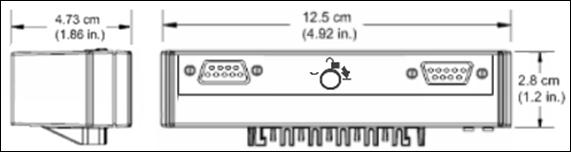
5 Hardware Specifications Common Environmental Specifications (all components) Operating temperature Storage temperature Relative humidity -40 to 70 C (-40 to 158 F)* -40 to 85 C (-40 to 185 F) 5 to 95%, non-condensing Protection rating IP 20 Airborne contaminants Shock ISA-S Airborne Contaminants Class G3 Conformal coating 10 g ½-sine wave for 11 ms Vibration 1 mm peak-to-peak from 2 to 13.2 Hz; 0.7 g from 13.2 to 150 Hz *When used with copper Ethernet I/O Ports (Copper IOP). When used with the Fiber Optic I/O Ports (Fiber Optic IOP), the operating temperature range is limited to -40 to 60 C (-40 to 140 F). CHARM I/O Card and Carrier. 5

.")

6 Uplink Port Uplink Port Cascade Port Copper IOP Fiber Optic IOP Operating Temperature -40 to 70 C (-40 to 158 F). Operating Temperature -40 to 60 C (-40 to 140 F). CIOC Carrier Ethernet Communication Modules IS CHARM Baseplate with Separator, IS CHARMs and Label Plates in Place. 6


7 CHARM Baseplate Terminator, Top. CHARM Baseplate Terminator, Bottom. CHARM Baseplate Extender, Top. CHARM Baseplate Extender, Bottom. 7
8 IS CHARM. IS CHARM Terminal Block. 8
9 IS CHARM Thermocouple/mV Terminal Block. Address Plug. 9
10 Address Plug Terminal Block for IS Baseplate. 10
11 CHARM I/O Card Hardware Specifications for CHARM I/O Card Carrier Number of I/O cards per carrier Input power (redundant) Redundant ethernet connections Mounting 2 (redundant pair) 24V DC ±10% at 12 A maximum Fiber-optic: 100BASE-FX with MTRJ connectors; Full duplex operation; Multi-mode - 2 km nominal distance. Copper twisted pair: 10/100BASE-TX with RJ45 connectors; Half/Full duplex operation 100 m distance DIN rail Latch to T-type rail Specifications for CHARM I/O Card Number of I/O channels Number of I/O clients 96 Channels, individually defined signal types 4 (Controllers) Number of CIOC s per controller 16 Number of CIOC s per system 300 I/O update rates User memory CIOC power (24V DC) CIOC heat dissipation CIOC output to CHARMs Fuse protection (internal) Mounting Communication Network addressing 50ms, 100ms, 250ms, 500ms N/A 0.28 Amps per Redundant CIOC node (includes two cards and two communication modules) (individual CHARM power requirements are in addition) 8 Watts max. per Redundant CIOC node 2.0 Watts per CIOC 1.34 Watts per Copper Ethernet I/O Communication Port 2.0 Watts per Fiber Optic I/O Communication Port 6.3V DC redundant power, at 3.25 A maximum* Internal Non-replaceable Fuse 2-wide CHARM I/O Carrier Redundant Ethernet connections via CHARM I/O Carrier Auto Assigned during commissioning LED Indicators Green Power Red Error Green Active/Standby Yellow flashing Pri./Sec. CN Indicates DC power is applied Indicates an error condition Indicates operating mode of each CIOC Indicates valid control network communication * Actual CIOC Output to CHARMs is dependent on number of installed CHARMs. 11
12 IS CHARMs Baseplate Hardware Specifications for IS CHARM Baseplate Number of channels per baseplate 12 Number of base plates per CIOC 8 Addressing One address plug (1 through 8) Terminal blocks Shield connections Wire strip length Mounting Shield drain wire connections Wire strip length Standard IS Terminal Block (Light Blue) IS Thermocouple / mv Terminal Block (Light Blue) 1 screw cage terminal per channel, plus 1 for cable shield mm2 / AWG Gold plated connectors for shield continuity 7-9 mm / in. DIN rail Latch to T-type rail Specifications for IS Baseplate Termination, Top and Bottom 2 screw cage terminals mm2 / AWG 7-9 mm / in. Primary bus connection Secondary bus connection Maximum bus length (including Baseplates) Specifications for Baseplate Extenders, Top and Bottom Specifications for Extender Cables 9-pin D-shell, Primary RS-485 communications bus Primary 24V DC field power Primary CHARM power 9-pin D-shell, Secondary RS-485 communications bus Secondary 24V DC field power Secondary CHARM power 5.5 m (18 ft) Available cable lengths 2 m, 1 m, 0.5 m (6.7 ft, 3.3 ft, 1.6 ft ) Number of connections Strip length Specifications for IS Terminal Block 4 screw cage terminals mm2 / AWG 7-9 mm / in. Maximum current 45 ma at 28V DC max. * Color Light blue 12
13 Number of connections Strip length Color Number of connections Color Specifications for IS Thermocouple / mv Terminal Block 2 screw cage terminals mm2 / AWG 7-9 mm / in. Light blue Specifications for Address Plug Terminal Block none Black *Actual Current draw is determined by type of CHARM and associated field devices. IS Analog Input CHARM Sensor types Nominal signal range (span) Full signal range Input impedance Field power (2-wire) Specifications for IS AI 4-20 ma HART CHARM 4-20 ma with or without HART Supports 2-wire and 4-wire device types 4-20 ma, (0-20 ma optional) 0 to 22 ma <303 Ω 16.0V (min) at 20 ma Accuracy over temperature range 0.1% of span (0-60º C) 0.25% of span (over ºC) Repeatability 0.05% of span Resolution Calibration DC/50/60 Hz common mode rejection 16bit A/D converter None required N/A Isolation Galvanically isolated according to EN Voltage peak value 375V DC. CHARM power req. 60 ma 24V DC ±10% CHARM heat dissipation HART support HART data update rates 0.86 W HART v7 pass-through for AMS HART v7 variable and device status available to control Typically less than one second but dependent on HART communication loading and the capability of the HART device 13

14 Simplified Circuit and Connection Diagrams for IS AI-CHARM4 to 20 ma HART Two Wire and Four Wire transmitters. 14
15 IS RTD CHARM Sensor types Sensor configuration Full scale signal range Accuracy Repeatability Resolution Calibration Sensor excitation current DC/50/60 Hz common mode rejection Specifications for IS RTD Input CHARM RTD input (Types listed in Table) 2 wire, 3 wire, or 4 wire See table below See table below 0.05% of span 24 bit A/D converter / depends upon the sensor type None required 0.5 ma in 2-wire and 4 wire configurations 0.25 ma in 3-wire 90dB typical Isolation Galvanically isolated according to EN Voltage peak value 375V DC Open sensor detection Yes CHARM power req. CHARM heat dissipation 23 ma 24V DC 0.60 W Sensor Type Operating Range RTD, ohms Sensor Type Specifications 25 Reference Accuracy (4-wire) Temperature Drift (4-wire) Pt to 850 C ± 0.50 C ± C/ C ~0.02 C Pt to 850 C ± 0.40 C ± C/ C ~0.02 C Pt to 850 C ± 0.34 C ± C/ C ~0.02 C Pt to 260 C ± 0.14 C ± C/ C ~0.01 C Ni to 260 C ± 0.18 C ± C/ C ~0.01 C Ni to 260 C ± 0.12 C ± C/ C ~0.01 C Ni to 260 C ± 0.11 C ± C/ C ~0.01 C Ni to 260 C ± 0.08 C ± C/ C ~0.01 C Ni to 140 C ± 0.06 C ± C/ C ~0.01 C Cu to 260 C ± 0.70 C ± C/ C ~0.01 C Resistance/User Defined* 0 to 2,000 Ω ± 0.50 Ω ± Ω/ C ~0.031 Ω Resolution * The Callendar-Van Dusen linearization equation can be used with user defined Pt RTDs. Refer to Recommended I/O Practices in DeltaV Books online for usage information. 15
16 Simplified Circuit and Connection Diagrams for IS RTD CHARM. 16
17 IS Thermocouple/mV CHARM Sensor types Thermocouple mv Full scale signal range Accuracy Repeatability Resolution Calibration Specifications for IS Thermocouple/mV Input CHARM B, E, J, K, N, R, S, T, uncharacterized Low level voltage source (±20 mv, ±50 mv, and ±100 mv) See table below See table below 0.05% of span 24 Bit A/D converter / depends upon the sensor type None required Cold junction compensation(cjc) Accuracy Range ± 0.7ºC -40 to 85ºC Temperature drift 0.03 C/ C Isolation Galvanically isolated according to EN , voltage peak value 375V DC Open sensor detection Yes CHARM power req. CHARM heat dissipation 23 ma 24V DC 0.60 W B Sensor Type 25 Reference Accuracy 1 ± 2.50 C ± 1.70 C Sensor Type Specifications Temperature Drift ± 0.07 C/ C ± 0.05 C/ C Nominal Resolution Full Scale Operating Range ~ C 0 to 1820 C 250 to 400 C 400 to 1820 C E ± 0.60 C ± 0.03 C/ C ~ C -270 to 1000 C -200 to 1000 C J ± 0.70 C ± 0.03 C/ C ~ C -210 to 1200 C -200 to 1200 C K ± 1.20 C ± 0.05 C/ C ~ C -270 to 1372 C -200 to 1370 C N ± 1.10 C ± 0.04 C/ C ~ C -270 to 1300 C -200 to 1300 C R ± 1.70 C ± 0.06 C/ C ~ C -50 to 1768 C -50 to 1767 C S ± 1.90 C ± 0.07 C/ C ~ C -50 to 1768 C -50 to 1767 C T ± 0.70 C ± 0.02 C/ C ~ 0.01 C -270 to 400 C -200 to 400 C ± 100 mv 50 μv ± 2.5 μv/ C ~ mV -100 to 100 mv -100 to 100 mv ± 50 mv 40 μv ± 1.7 μv/ C ~ mV -50 to 50 mv -50 to 50 mv ± 20 mv 20 μv ± 0.8 μv/ C ~ mV -20 to 20 mv -20 to 20 mv 1 Total error is made up of the 25 C reference accuracy value, plus the CJC accuracy value, plus the sensor accuracy value. 17

18 Simplified Circuit and Connection Diagram for IS Thermocouple/mV CHARM with IS Thermocouple/mV Terminal Block. 18
 0 to 22 ma 750 Ohm max. 15V (min) @ 20 ma 0.25% of span (0 to 60ºC) 0.")
19 IS Analog Output CHARM Sensor types Nominal signal range (span) Full signal range Load resistance Voltage to load Accuracy over temperature range Resolution Calibration Specifications for IS AO 4-20 ma HART CHARM 4 to 20 ma with or without HART 4-20 ma, (0-20 ma optional) 0 to 22 ma 750 Ohm max. 15V 20 ma 0.25% of span (0 to 60ºC) 0.5% of span (-40 to 70ºC) 16 bit A/D converter None required Isolation Galvanically isolated according to EN Voltage peak value 375V DC CHARM power req. 56 ma 24V DC ±10% CHARM heat dissipation HART support HART data update rates 1.1 W HART v7 pass-through for AMS HART v7 variable and device status available to control Typically less than one second but dependent on HART communication loading and the capability of the HART device Simplified Circuit and Connection Diagram for IS AO HART CHARM. 19

20 IS Discrete Input CHARM Sensor types Detection level for On Detection level for Off Specifications for IS DI NAMUR CHARM NAMUR sensors, dry contacts >2.1 ma <1.2 ma Channel impedance 1kOhm ± 10% Wetting voltage 8V DC ± 1V DC Fault detection capable with NAMUR sensor or with an optional field resistor pack as shown on Option 2 in diagram below (Option 1 in diagram below is not fault detection capable) Configurable channel types: Discrete input Pulse count Guaranteed short circuit: <100 Ω Guaranteed good status: 360 Ω to 20 kω Guaranteed open circuit: > 75 kω Dry contact or discrete state sensor changing <2 Hz Pulse train 0.1 Hz to 10 KHz, 50 µsec min pulse width Isolation Galvanically isolated according to EN Voltage peak value 375V DC CHARM power req. 28 ma 24V DC ±10% CHARM heat dissipation 0.57 W Simplified Circuit and Connection Diagram for IS DI NAMUR CHARM. 20
21 IS Discrete Output CHARM Device type On state output rating Off state leakage current Line fault detection Configurable output behavior Line fault test timing Specifications for IS DO 45 ma CHARM Solenoid Coils 22V to 25V (open circuit); 11V at 45 ma 230μA Guaranteed short circuit: <100 Ω load Guaranteed good status: 150 Ω to 20 kω load Guaranteed open circuit: >25 kω load Momentary output Continuous pulse output Line fault testing 180 to 220 µsec Isolation Galvanically isolated according to EN Voltage peak value 375V DC CHARM power req. 78 ma 24V DC ±10% CHARM heat dissipation 1.4 W Simplified Circuit and Connection Diagram for IS DO 45 ma CHARM. 21
22 System Compatibility IS CHARM I/O hardware requires: SD Plus controllers with DeltaV v or later software SX controllers with DeltaV v or later software SQ controllers with v or later software S-series and M-series controllers can be installed on the same DeltaV Area Control Network in v11 and beyond. Control modules can be assigned to either series of controller and inter-controller references are fully supported between controller series. CHARM I/O Card: IS CHARMs installed on IS CHARM baseplates canbe connected to a CHARM I/O Card carrier, using a baseplate separator and a special fuse in each of the two the power supply lines of the CHARM I/O carrier. Non-IS CHARM Baseplates: Non-IS CHARM baseplates can be extended with CHARM baseplates, using a baseplate separator. IS CHARM Baseplates: IS CHARM baseplates cannot be extended withnon-is CHARM Baseplates. Baseplate Extender: IS CHARM baseplates can be connected to CHARM baseplate extenders using baseplate separators. Baseplate Terminator: IS CHARM baseplates can be connected to CHARM baseplate terminators using baseplate separators. Refer to installation instructions for rules governing IS wiring. Certifications The following certifications are available for S-series IS Electronic Marshalling: CE: EMC - EN FM: FM 3600 FM 3610 FM 3611 CSA: CSA-C22.2 No CSA-C22.2 No CSA-C22.2 No CSA-C22.2 No CSA-C22.2 No ATEX: EN EN EN EN IEC-Ex: IEC IEC IEC IEC Marine Certifications: IACS E10 ABS Certificate of Design Assessment DNV-GL Marine Certificate Wurldtech: CIOC Achilles Communications Certification Level 1 (v ) 22
23 Hazardous Area/Location S-series IS Electronic Marshalling can be installed and used based on the following Standards: FM (USA) Installation: Class I, Division 2, Groups A, B, C, D, T4 Class I, Zone 2 AEx nac IIC Field Circuits: Class I, Division 1, Groups A, B, C, D Class II, Division 1, Groups E, F, G Class III Class I, Zone 0 [AEx ia] IIC cfm (Canada) ATEX Installation: II 3 (1) G Ex na [ia Ga] IIC Gc Field Circuits: II (1) G [Ex ia Ga] IIC II (1) D [Ex ia Da] IIIC IEC-Ex Installation: Ex na [ia Ga] IIC Gc Field Circuits: [Ex ia Ga] IIC [Ex ia Da] IIIC Installation: Class I, Division 2, Groups A, B, C, D, T4 Class I, Zone 2 Ex na IIC Field Circuits: Class I, Division 1, Groups A, B, C, D Class II, Division 1, Groups E, F, G Class III Class I, Zone 0 [Ex ia] IIC Regarding the Installation instructions please refer to the following Documents: ATEX/IECEx Installation Instructions IS-CHARM Subsystem 12P6523 Control Drawing DeltaV IS-CHARMs Subsystem 12P6122 Control Drawing DeltaV IS-CHARMs 12P
24 Ordering Information CHARM I/O CARD Description Redundant CIOC with Copper Ethernet, includes redundant pair of CHARM I/O Cards, CHARM I/O Carrier with Screw Terminals, Copper I/O Ports, a Baseplate Identifier and a Baseplate Separation Wall Redundant CIOC with fiber optics Ethernet, includes redundant pair of CHARM I/O Cards, CHARM I/O Carrier with Screw Terminals, Fiber-Optic I/O Ports, a Baseplate Identifier and a Baseplate Separation Wall Redundant CIOC Carrier Assembly with Copper Ethernet, includes CHARM I/O Carrier with Screw Terminals, Copper I/O Ports, a Baseplate Identifier and a Baseplate Separation Wall Redundant CIOC Carrier Assembly with fiber optics Ethernet, includes CHARM I/O Carrier with Screw Terminals, Fiber-Optic I/O Ports, a Baseplate Identifier and a Baseplate Separation Wall Redundant CIOC, includes 2 CHARMS I/O Cards, (Order these with standard cabinets) Model Number SE6501T01 SE6501T02 SE6501T05 SE6501T06 SE6502 IS CHARM Baseplates Description IS CHARMS Baseplate Assembly with Standard IS CHARM Terminal Blocks, includes IS CHARMS Baseplate, IS CHARM Address Terminal Block, 12 IS CHARM Standard Terminal blocks and a Baseplate Separation Wall CHARM I/O Baseplate Address Plugs Description Addressing Plugs, includes Address Plugs 1 through 8 Addressing Plugs, includes Address Plugs 1 through 4 Model Number SE4608T01 Model Number SE4602 SE4613 CHARM I/O Baseplate Extender, Terminator & Cables Description CHARMs Baseplate Extender with Cable Connectors, Top (Male) includes a Baseplate Identifier and a Baseplate Separation Wall CHARMs Baseplate Extender with Cable Connectors, Bottom (Female) includes a Baseplate Identifier and a Baseplate Separation Wall CHARMs Baseplate Terminator, Top (Male) includes a Baseplate Identifier and a Baseplate Separation Wall CHARMs Baseplate Terminator, Bottom (Female) includes a Baseplate Identifier and a Baseplate Separation Wall CHARMs Baseplate Cables, includes two 0.5m cables CHARMs Baseplate Cables, includes two 1m cables CHARMs Baseplate Cables, includes two 2m cables Model Number SE4603T05 SE4603T06 SE4604T03 SE4604T04 SE4605T02 SE4605T03 SE4605T04 Each vertical DIN rail requires a DIN Rail stop to lock baseplates in position. Order VE4054DRS, which is a box of
25 Ordering Information IS CHARMs Description Model Number IS DI NAMUR IS DO 45 ma IS AI 4-20 ma HART IS AO 4-20 ma HART IS Thermocouple/mV IS RTD SE4305T01 SE4306T01 SE4307T01 SE4308T01 SE4309T01 SE4310T01 IS CHARMs and IS Terminal Block Assembly s Description IS Thermocouple/mV CHARM with IS Thermocouple/mV Terminal Block Model Number SE4309T51 Additional Ordering Information for IS CHARM Protection Cover IS CHARM Protection Cover Description Model Number IS CHARM Protection Cover; Package of 12 SE6104 Simplified Circuit and Connection Diagram for IS CHARM Protection Cover. When the I.S. CHARM Protection Cover is installed, all terminals on the I.S. CHARM Terminal Block are shortened! The shortened Terminals can be connected to Chassis Ground, while allowing the ground to be Daisy chained to the next I.S. CHARM Terminal block, where the next I.S. CHARM Protection Cover got installed. 25

26 Prerequisites S-Series IS Electronic Marshalling hardware requires DeltaV v or later software. IS CHARM FUSE Description Fuse Holder and Fuse Assembly for 24VDC Power Supply of CHARM I/O CARD Model Number SE4610T01* * Two of these Fuse Assemblies have to be ordered with any SE6501T01 or SE6501T02, when used with IS CHARM baseplates. Outside Dimensions of the Fuse Holder. CHARM I/O Spare Part Ordering Information CHARM I/O Spare Parts Description Model Number Power Terminal Plug for CHARM I/O Carrier I/O Port Switch Module; Copper; for CIOC Carriers I/O Port Switch Module; Fiber; for CIOC Carriers KJ4005X1-BF1 KL1601X1-BA1 KL1602X1-BA1* * Fiber Optic Ethernet I/O Ports are not cascade able. IS CHARM I/O Labeling Ordering Information IS CHARM I/O Labeling Parts Description Channel Identifier Labels for Intrinsically-Safe CHARM Baseplates; Package of 8 IS Charm Baseplate Separation Wall; Package of 9 Replacement Fuse for SE4610T01 Fuseholder Assembly Replacement Fuseholder for SE4610T01 Fuseholder Assembly Model Number SE4609T01 SE4609T02 KL4510X1-FA1 KL4510X1-GA1 26
27 Product Data Sheet Emerson North America, Latin America: or Asia Pacific: Europe, Middle East: , Emerson. All rights reserved. The Emerson logo is a trademark and service mark of Emerson Electric Co. The DeltaV logo is a mark of one of the Emerson family of companies. All other marks are the property of their respective owners. The contents of this publication are presented for informational purposes only, and while every effort has been made to ensure their accuracy, they are not to be construed as warranties or guarantees, express or implied, regarding the products or services described herein or their use or applicability. All sales are governed by our terms and conditions, which are available on request. We reserve the right to modify or improve the designs or specifications of our products at any time without notice.
DeltaV IS Electronic Marshalling
 DeltaV Distributed Control System Product Data Sheet October 2017 DeltaV IS Electronic Marshalling Intrinsically Safe I/O anywhere you need it Integrated galvanic Isolation per channel Reduces installed
S-series Electronic Marshalling
 DeltaV Distributed Control System Product Data Sheet July 2017 S-series Electronic Marshalling I/O anywhere you need it Single channel granularity Reduces installed cost of system Fully redundant architecture
S-series IS Electronic Marshalling
 January 2013 Page 1 The DeltaV CHARM I/O Card (CIOC) with IS CHARMS Intrinsically Safe I/O anywhere you need it Integrated galvanic Isolation per channel Reduces installed cost of system Fully redundant
DeltaV Electronic Marshalling for Migrations
 DeltaV Distributed Control System Product Data Sheet DeltaV Electronic Marshalling for Migrations I/O anywhere you need it Single channel granularity Replaces legacy I/O in place Fully redundant architecture
S-series Electronic Marshalling
 April 2013 Page 1 S-series Electronic Marshalling The DeltaV CHARM I/O Card (CIOC) with CHARMs I/O anywhere you need it Single channel granularity Reduces installed cost of system Fully redundant architecture
DeltaV Electronic Marshalling
 DeltaV Distributed Control System Product Data Sheet DeltaV Electronic Marshalling I/O anywhere you need it Single channel granularity Reduces installed cost of system Fully redundant architecture Field-mounted
S-series Electronic Marshalling
 DeltaV Distributed Control System Product Data Sheet S-series Electronic Marshalling I/O anywhere you need it Single channel granularity Reduces installed cost of system Fully redundant architecture Field-mounted
S-series Electronic Marshalling for Migrations
 March 2013 Page 1 S-series Electronic Marshalling for Migrations S-series CHARM I/O Cards (CIOC) mounted on a Migration Panel S-series CHARM I/O Baseplate Migration Panel. I/O anywhere you need it Single
DeltaV SX Controller. Introduction. Benefits. Scalable controllers. Quick assembly. Easy to use. Field proven architecture
 DeltaV Distributed Control System Product Data Sheet January 2018 DeltaV SX Controller Scalable controllers Quick assembly Easy to use Field proven architecture Designed for Electronic Marshalling Advanced
DeltaV Safety Instrumented System (SIS) with IS Electronic Marshalling
 with IS Electronic Marshalling") DeltaV SIS Process Safety System Product Data Sheet October 2017 DeltaV Safety Instrumented System (SIS) with IS Electronic Marshalling Intrinsically Safe I/O anywhere you need it Integrated galvanic isolation
DeltaV SIS Process Safety System Product Data Sheet October 2017 DeltaV Safety Instrumented System (SIS) with IS Electronic Marshalling Intrinsically Safe I/O anywhere you need it Integrated galvanic isolation
DeltaV SQ Controller. Introduction. Benefits. Scalable controllers. Quick assembly. Easy-to-use. Field proven architecture
 DeltaV Distributed Control System Product Data Sheet January 2018 DeltaV SQ Controller Scalable controllers Quick assembly Easy-to-use Field proven architecture Designed for Electronic Marshalling Advanced
S-series Horizontal Carriers
 DeltaV Distributed Control Systems Product Data Sheet S-series Horizontal Carriers The DeltaV modular I/O subsystem is easy to install and maintain Modular design allows flexible installation Allows you
S-series Mass Connection Solutions
 DeltaV Distributed Control System Product Data Sheet August 2017 S-series Mass Connection Solutions Fast, easy and error-free cabinet wiring Modular design, improves reliability Lowers overall termination
DeltaV Safety Instrumented System (SIS) with Electronic Marshalling
 with Electronic Marshalling") DeltaV SIS Process Safety System Product Data Sheet DeltaV Safety Instrumented System (SIS) with Electronic Marshalling Optimized process reliability Simplified safety lifecycle management Flexibility
DeltaV SIS Process Safety System Product Data Sheet DeltaV Safety Instrumented System (SIS) with Electronic Marshalling Optimized process reliability Simplified safety lifecycle management Flexibility
DeltaV MQ Controller. Introduction. Benefits. Increases productivity. Easy to use. Has the flexibility to meet your needs. Increases productivity
 DeltaV Distributed Control System Product Data Sheet October 2017 DeltaV MQ Controller Increases productivity Easy to use Has the flexibility to meet your needs Introduction The MQ Controller provides
M-series Intrinsically Safe I/O
 DeltaV Distributed Control System Product Data Sheet M-series Intrinsically Safe I/O Features full system modularity Reduces system footprint Decreases installation time and expense Plug-and-play installation
DeltaV MX Controller. Introduction. Benefits. Right-sized controllers. Easy to use. Has the flexibility to meet your needs
 DeltaV Distributed Control System Product Data Sheet October 2017 DeltaV MX Controller Right-sized controllers Easy to use Has the flexibility to meet your needs Designed to support legacy migration Introduction
Introduction. Delivers four ports to provide increased input/ output per card. Takes advantage of all smart device capabilities
 DeltaV Distributed Control System M-series Foundation TM Fieldbus Product Data Sheet Series 2 Plus I/O Use DeltaV state-of-the-art Foundation Fieldbus Series 2 Plus redundant I/O for your process control
DeltaV M-series Traditional I/O
 DeltaV Distributed Control System Product Data Sheet August 2018 DeltaV M-series Traditional I/O The DeltaV I/O subsystem is easy to install and maintain. Decreases capital equipment costs Decreases installation
DeltaV M-series Traditional I/O
 DeltaV Distributed Control System Product Data Sheet June 2018 DeltaV M-series Traditional I/O The DeltaV I/O subsystem is easy to install and maintain. Decreases capital equipment costs Decreases installation
DeltaV S-series Traditional I/O
 DeltaV Distributed Control System Product Data Sheet DeltaV S-series Traditional I/O Modular and flexible construction Reduced installation time and expense Easy online expansion Field-mounted capable
DeltaV M-series Traditional I/O
 DeltaV Distributed Control System Product Data Sheet DeltaV M-series Traditional I/O The DeltaV I/O subsystem is easy to install and maintain. Decreases capital equipment costs Decreases installation time
S-series Foundation Fieldbus I/O
 DeltaV Distributed Control System Product Data Sheet S-series Foundation Fieldbus I/O Use DeltaV state-of-the-art S-series FOUNDATION fieldbus I/O for your process control system. Increase I/O capacity
M-series MQ Controller
 DeltaV Distributed Control System Product Data Sheet M-series MQ Controller Increases productivity Easy to use Has the flexibility to meet your needs Introduction The MQ Controller provides communication
M-series Traditional I/O
 January 2013 Page 1 The DeltaV I/O subsystem is easy to install and maintain. Decreases capital equipment costs Decreases installation time and expense Increases productivity Increases process availability
DeltaV SX Controller. DeltaV SX Controller. Introduction. DeltaV Product Data Sheet. Scalable controllers. Quick Assembly.
 August 2010 Page 1 The and the DeltaV I/O subsystem make rapid installation easy Scalable controllers Quick Assembly Easy to use Field Proven architecture Designed for Digital Marshalling Advanced Controls
DeltaV SD Plus Controller
 August 2010 Page 1 The and the DeltaV I/O subsystem make rapid installation easy Scalable controllers Quick Assembly Easy to use Field Proven architecture Designed for Digital Marshalling Advanced Controls
M-series MX Controller
 DeltaV Distributed Control System Product Data Sheet June 2017 M-series MX Controller Right-sized controllers Easy to use Has the flexibility to meet your needs Designed to support legacy migration Introduction
S-series Sequence of Events Card
 DeltaV Distributed Control Systems Product Data Sheet S-series Sequence of Events Card DeltaV Sequence of Events delivers high-resolution data capture for your easy analysis. Captures process upset events
DeltaV M-series I/O Subsystem Horizontal Carriers
 DeltaV Distributed Control System Product Data Sheet DeltaV M-series I/O Subsystem Horizontal Carriers The DeltaV modular I/O subsystem is easy to install and maintain. Modular design allows flexible installation
DeltaV Bulk Power Supplies
 DeltaV Distributed Control System Product Data Sheet DeltaV Bulk Power Supplies DeltaV 5 A, 10A, 20 A, 40 A Bulk Power Supplies. DeltaV 20 A, 40 A and 80 A Bulk Power Supply Redundancy Modules. Easy to
DeltaV Wireless I/O Card
 DeltaV Distributed Control System Product Data Sheet October 2017 DeltaV Wireless I/O Card Fully redundant wireless solution from Wireless I/O Card (WIOC) to the Smart Wireless Field Link Optional simplex
DeltaV VerticalPlus I/O Subsystem Carriers
 DeltaV Distributed Control System Product Data Sheet DeltaV VerticalPlus I/O Subsystem Carriers Designed for SIS Modular design allows flexible installation Allows you to expand online Increases I/O density
DeltaV Ethernet I/O Card
 DeltaV Distributed Control System Product Data Sheet October 2017 DeltaV Ethernet I/O Card Powerful solution that communicates directly to external Ethernet Device Networks Easy connection to devices using
S-series Horizontal Carriers
 January 2013 Page 1 The DeltaV modular I/O subsystem is easy to install and maintain Modular design allows flexible installation Allows you to expand online Integrated power distribution Snap in assembly
DeltaV Bulk Power Supplies
 DeltaV Distributed Control System Product Data Sheet DeltaV Bulk Power Supplies DeltaV 5 A, 10A, 20 A, 40 A Bulk Power Supplies. DeltaV 20 A, 40 A and 80 A Bulk Power Supply Redundancy Modules. Easy to
DeltaV PK Controller. Benefits. Introduction. Powerful Standalone. Easily Integrated. Fast process control applications
 DeltaV Distributed Control System Product Data Sheet February 2018 DeltaV PK Controller Powerful Standalone. Easily Integrated. Fast process control applications Designed for use with any DeltaV I/O family
S-series DeviceNet Interface Card
 DeltaV Distributed Control System Product Data Sheet S-series DeviceNet Interface Card The DeltaV S-series DeviceNet Interface Card provides the solution for interfacing to discrete actuators and sensors.
S-Series DeltaV Controller Interface for PROVOX I/O
 DeltaV Distributed Control System Product Data Sheet S-Series DeltaV Controller Interface for PROVOX I/O The S-Series DeltaV Controller Interface for PROVOX I/O. I Provides a fast and easy upgrade for
DeltaV SIS Conditioning Components
 DeltaV SIS Process Safety System DeltaV SIS Conditioning Components The DeltaV SIS conditioning components allow you to use the DeltaV SIS system with a variety of different field signal requirements.
M-series Foundation Fieldbus I/O
 DeltaV Distributed Control System Product Data Sheet M-series Foundation Fieldbus I/O Use DeltaV state-of-the-art FOUNDATION Fieldbus redundant I/O for your process control system. Increases input/output
S-series Ethernet I/O Card
 DeltaV Distributed Control System Product Data Sheet S-series Ethernet I/O Card Powerful solution that communicates directly to external Ethernet Device Networks Easy connection to devices using Modbus
S-series H1 I/O Card with Integrated Power
 January 2013 Page 1 S-series H1 I/O Card with Integrated Power Use DeltaV state-of-the-art for your process control system. Increase I/O capacity while reducing wiring Maximize smart device capabilities
DeltaV SIS TM. Logic Solver. DeltaV SIS Logic Solver. Introduction. DeltaV SIS Product Data Sheet. World s first smart SIS Logic Solver
 February 2016 Page 1 DeltaV SIS TM Logic Solver The DeltaV SIS platform is the world s smart SIS system to use the power of predictive intelligence for increasing the availability of the entire safety
M-series Profibus DP Series 2 Plus Interface Card
 DeltaV Distributed Control Systems Product Data Sheet M-series Profibus DP Series 2 Plus Interface Card The DeltaV M-series Profibus DP Interface Card provides the solution for interfacing to discrete
M-series I/O Subsystem Horizontal Carriers
 February 2016 Page 1 DeltaV M-series I/O Subsystem Horizontal Carriers DeltaV M-series I/O Subsystem Horizontal Carriers The DeltaV modular I/O subsystem is easy to install and maintain. Modular design
M-series Virtual I/O Module 2
 DeltaV Distributed Control System Product Data Sheet M-series Virtual I/O Module 2 Non-intrusive DeltaV I/O simulation Powerful integration solution Easy to use Modular, flexible packaging The M-series
DeltaV Control Network Hardware
 DeltaV Distributed Control System Product Data Sheet January 2018 DeltaV Control Network Hardware Easy to use Scalable and cost-effective Built-in network diagnostics Fully redundant network The DeltaV
S-series Virtual I/O Module 2
 DeltaV Distributed Control System Product Data Sheet March 2017 S-series Virtual I/O Module 2 Non-intrusive DeltaV I/O simulation Powerful integration solution Easy to use Modular, flexible packaging The
S-series Sequence of Events Card
 March 2013 Page 1 DeltaV Sequence of Events delivers high-resolution data capture for your easy analysis. Captures process upset events close to the source for precise recording Provides increased resolution
M-series DeltaV Controller Interface for PROVOX I/O
 January 2013 Page 1 M-series DeltaV Controller Interface for PROVOX I/O PROVOX I/O Interface Modules DeltaV Railbus C Control I/O Bus with Redundant Connections Upgrade your PROVOX controllers with the
S-series Profibus DP Interface Card
 January 2013 Page 1 The DeltaV provides the solution for interfacing to discrete actuators and sensors. Integrates Profibus DP device signals directly into control logic Reduces wiring costs Native bus
DeltaV SIS TMConditioning Components
 February 2016 Page 1 DeltaV SIS TMConditioning Components The DeltaV SIS conditioning components allow you to use the DeltaV SIS system with a variety of different field signal requirements. Enables diagnostics
M-series Serial Interface Series 2
 DeltaV Distributed Control System Product Data Sheet M-series Serial Interface Series 2 The DeltaV Serial Interface provides a connection between the DeltaV system and other devices. Provides seamless
CTO CSLS CHARM Cabinets
 DeltaV SIS Process Safety System Product Data Sheet November 2017 CTO CSLS CHARM Cabinets Rear View CTO CSLS CHARM Cabinet. Delivers Electronic Marshalling enabled by CHARMs technology Reduce system footprint
Introduction. DeltaV Product Data Sheet February 2016 Page 1. M-series MX Controller. Right-sized controllers. Easy to use
 February 2016 Page 1 The DeltaV MX Controller and the DeltaV I/O subsystem make rapid installation easy. Right-sized controllers Easy to use Has the flexibility to meet your needs Designed to support legacy
M-series DC to DC Power Supply
 February 2016 Page 1 M-series DC to DC Power Supply Enhanced The DeltaV M-series Enhanced DC/DC system power supplies are modular, easy to install, and secure Easy to use Flexible and cost-effective Secure
M-series MQ Controller
 February 2016 Page 1 The DeltaV MQ Controller and the DeltaV I/O subsystem make rapid installation easy. Increases productivity Easy to use Has the flexibility to meet your needs Introduction The MQ Controller
FLEX Ex Spring Clamp Terminal Base
 Installation Instructions FLEX Ex Spring Clamp Terminal Base (Cat. No. 1797-TB3S) 1 10 11 4 Only remove this cover plug if connecting another terminal base unit. 3 5 6 12 2 7 8 9 41253 Component Identification
M-series Profibus DP Series 2 Plus Interface Card
 January 2013 Page 1 M-series Profibus DP Series 2 Plus Interface Card The DeltaV M-series Profibus DP Interface Card provides the solution for interfacing to discrete actuators and sensors. Offers freedom
Termination Board FC-GPCS-RIO16-PF. Features. Assembly. Function. Connection USIO/UPIO 24 V DC (I), 24 V DC (II) Fault. Zone 0, 1, 2 Div.
, 24 V DC (II) Fault. Zone 0, 1, 2 Div.") Features Assembly System board for Honeywell Universal Safety IO System board for Honeywell Universal Process IO For 6-channel cards USIO and UPIO For 6 modules Recommended modules: HiC8R (DI), HiC85R
Features Assembly System board for Honeywell Universal Safety IO System board for Honeywell Universal Process IO For 6-channel cards USIO and UPIO For 6 modules Recommended modules: HiC8R (DI), HiC85R
Engineering Guideline. pac-carriers Type for Honeywell system Experion Series C I/O
 Engineering Guideline pac-carriers Type 995 for Honeywell system Experion Series C I/O pac-carrier Type 995 Engineering Guideline/Honeywell 04..009 pac-carrier Type 995 Integration of conventional process
M-series DeltaV Controller Interface for RS3 I/O
 January 2013 Page 1 M-series DeltaV Controller Interface for RS3 I/O RS3 I/O Interface Modules DeltaV Railbus Connection RS3 I/O Interface Carrier RS3 I/O Connectors (8) Upgrade your RS3 ControlFiles with
Terminal Block Catalog Numbers 1719-TB6, 1719-TB6S, 1719-TB8, 1719-TB8S, 1719-TB8Sx2, 1719-TB8x2
 Technical Data Communication Adapter Catalog Number 1719-AENTR I/O Module Catalog Numbers 1719-IJ, 1719-IBN8B, 1719-IF4HB, 1719-IR4B, 1719-IT4B, 1719-OB2, 1719-OB2L, 1719-CF4H Power Supply Catalog Number
Assembly MAU. MUX 4 Channels 8 Channels Zone 1
 Multi-Input/Output Device for Cabinet Installation Features Assembly For discrete inputs and outputs Installation in Zone 1/Div. 1, intrinsically safe Sensors in Zone 0/Div. 1 Connection to fieldbus acc.
S-series Serial Interface
 January 2013 Page 1 The DeltaV provides a connection between the DeltaV system and other devices Provides seamless information interface Plug-and-play easy to use Extends the life of existing equipment
Digital Output Module 8-Channel Version for Zone 2 Series 9475/
 > 8-channel digital output > Intrinsically safe outputs Ex ia > For Ex i solenoid valves and display elements > Line fault monitoring per channel > Diagnostics based on NE107 > Module can be replaced in
CTO CHARM Field Enclosure
 DeltaV Distributed Control System Product Data Sheet November 2017 CTO CHARM Field Enclosure Configure to Order (CTO) CHARM Field Enclosures. Delivers Electronic Marshalling enabled by CHARacterization
Digital Output Module 4-Channel Version for Zone 1 Series 9475/
 www.stahl.de > 4-channel digital output > Intrinsically safe outputs Ex ib > Suitable for Ex i hydraulic valves and solenoid valves > Additional Ex i control input for (in accordance with IEC 61508 through
About the FLEX I/O and FLEX Ex I/O Systems
 Section 1.1 About the FLEX I/O and FLEX Ex I/O Systems 1794 FLEX I/O Overview FLEX I/O offers: Adapter Terminal base I/O module FlexBus connectors Keyswitch FlexBus connectors 2 2 + + Network Connector
S-series DeviceNet Interface Card
 January 2013 Page 1 The DeltaV provides the solution for interfacing to discrete actuators and sensors. Offers freedom to choose appropriate bus for application Supports standard device-level busses Reduces
Safety Barriers. CEAG safety barriers can be used for all kinds of instrumentation applications.
 Safety Barriers Description Safety barriers limit the energy fed to an intrinsically safe circuit so that neither sparks nor thermal effects (hot surfaces) can cause an explosion. CEAG safety barriers
Assembly MAU. MUX 4 Channels 8 Channels Zone 1
 Multi-Input/Output Device for Cabinet Installation Features Assembly For discrete inputs and outputs Installation in Zone 1/Div. 1, intrinsically safe Sensors in Zone 0/Div. 1 Connection to fieldbus acc.
4 Remote I/O. Analog Output Module HART Ex i / I.S. Outputs, 8 Channels Series 9466/12
 0 4 Remote I/O 8 channels for controlling HART control valves and positioners Intrinsically safe outputs Ex ia IIC Galvanic isolation between outputs and system Open-circuit and short-circuit monitoring
Termination Board FC-GPCS-SAI16-PF. Features. Assembly. Function. Connection. SAI-1620m HART 24 V DC (I), 24 V DC (II) Fault. Zone 0, 1, 2 Div.
, 24 V DC (II) Fault. Zone 0, 1, 2 Div.") Features Assembly System board for Honeywell Safety Manager For 6-channel AI card SAI-60m For 6 modules Recommended module: HiC05 (AI) 4 V DC supply Hazardous area: pluggable screw terminals, blue Non-hazardous
Features Assembly System board for Honeywell Safety Manager For 6-channel AI card SAI-60m For 6 modules Recommended module: HiC05 (AI) 4 V DC supply Hazardous area: pluggable screw terminals, blue Non-hazardous
Ethernet I/O Card. Ethernet I/O Card. Introduction. DeltaV Product Data Sheet. Easy to use. Powerful integration solution. Modular, flexible packaging
 August 2010 Page 1 The Ethernet IO Card provides a high speed Ethernet IO device integration platform Easy to use Powerful integration solution Modular, flexible packaging Introduction The DeltaV S-Series
Intrinsically Safe Barriers
 Intrinsically Safe Barriers Description Page No. Safety Barriers 464-472 Din Rail Isolated Barriers 473-488 477 Intrinsically Safe Barriers Product Overview We have simplified intrinsic safety! Cooper
Digital Output Module 8-Channel Version for Zone 1 Series 9475/
 www.stahl.de > 8-channel digital output > Intrinsically safe outputs Ex ia > For Ex i solenoid valves and display elements > Additional Ex i control input for "Plant STOP" (acc. IEC61508 up to SIL2) >
Digital Output Module 8-Channel Version for Zone 2 Series 9475/
 > 8-channel digital output > Intrinsically safe outputs Ex ia > For Ex i solenoid valves and display elements > Line fault monitoring per channel > Diagnostics based on NE107 > Module can be replaced in
THE BARRIER and the Universal Barrier Cabinets from Pepperl+Fuchs
 THE BARRIER and the Universal Barrier Cabinets from Pepperl+Fuchs Overview This document provides information relating to the use of THE BARRIER HiC2, the SMART universal barrier from Pepperl+Fuchs, a
RSTI-EP Slice I/O. Analog Input Modules `EP-3164, EP-3264, EP-3124, EP-3368, EP-3468 EP-3704, EP GFK-2960B November 2017
 November 2017 Module Status LED Channel Status LEDs Digital Input Connector Ground 24 V DC FE Analog Input Module RSTI-EP Slice I/O Analog Input Modules `EP-3164, EP-3264, EP-3124, EP-3368, EP-3468 EP-3704,
SEM310 SEM310X HART UNIVERSAL TEMPERATURE TRANSMITTER
 HART 5,6,7 COMPATABLE UNIVERSAL INPUT, DUAL CHANNEL ATEX & IEC Ex Version MATHS FUNCTIONS FLASH TESTED TO 4 KV DC INTRODUCTION The SEM310 is a HART 5 upwards, (generic device) compatible universal transmitter.
CTO CSLS Field Enclosure
 DeltaV SIS Process Safety System Product Data Sheet CTO CSLS Field Enclosure Delivers Electronic Marshalling enabled by CHARacterization Module (CHARM) technology Reduce system footprint Eliminate I/O
INSTALLATION INSTRUCTIONS
 www.altroniccontrols.com INSTALLATION INSTRUCTIONS EXACTA 21 MONITORING AND CONTROL SYSTEM CAUTION: The EXACTA 21 CONTROL SYSTEM is CSA CERTIFIED FOR use in Class I, GROUPS C & D, Division 2 hazardous
HART UNIVERSAL TEMPERATURE TRANSMITTER
 SEM310 / SEM310X HART 5,6,7 COMPATABLE UNIVERSAL INPUT, DUAL CHANNEL ATEX & IEC Ex Version MATHS FUNCTIONS SENSOR CHARACTERISTICS DOWNLOAD VIA USB PORT ALLOWS FOR CUSTOM TYPES FLASH TESTED TO 4 KV DC INTRODUCTION
Signal Conditioning Modules and Terminal Boards
 Signal Conditioning Modules and Terminal Boards Terminal Board Selection Guide 17-2 Isolated Signal Conditioning Modules ADAM-3000 Series Isolated Signal Conditioning Modules 17-4 ADAM-3011 ADAM-3013 ADAM-3014
RSTI-EP Slice I/O. Analog Input Modules `EP-3164, EP-3264, EP-3124, EP-3368, EP-3468 EP-3664, EP-3704, EP GFK-2960F September 2018
 September 2018 Module Status LED Channel Status LEDs Digital Input Connector Ground 24 V DC FE Analog Input Module RSTI-EP Slice I/O Analog Input Modules `EP-3164, EP-3264, EP-3124, EP-3368, EP-3468 EP-3664,
General Specifications
 General Specifications GS 32P06P10-01EN Models S2BN4D, S2BN5D Base Plates for Barrier (for N-IO) System Models: S2ZN4D, S2ZN5D N-IO I/O Unit GENERAL This General Specifications (GS) provides the specifications
HART UNIVERSAL TEMPERATURE TRANSMITTER
 SEM310 / SEM310X HART 5,6,7 COMPATABLE UNIVERSAL INPUT, DUAL CHANNEL ATEX & IEC Ex Version MATHS FUNCTIONS SENSOR CHARACTERISTICS DOWNLOAD VIA USB PORT ALLOWS FOR CUSTOM TYPES FLASH TESTED TO 4 KV A/C
S-series Serial Interface
 DeltaV Distributed Control System Product Data Sheet June 2017 S-series Serial Interface The DeltaV S-series Serial Interface provides a connection between the DeltaV system and other devices. Provides
Digital Output Module 4-Channel Version for Zone 1 Series 9475/
 www.stahl.de > 4-channel digital output > Intrinsically safe outputs Ex ia > For Ex i solenoid valves and display elements > Additional Ex i control input for "Plant STOP" (acc. IEC61508 up to SIL2) >
Trendmaster* Galvanic Isolator
 162459-01 Trendmaster* Galvanic Isolator Product Datasheet Bently Nevada* Asset Condition Monitoring Description The Trendmaster Galvanic Isolator enables the Trendmaster system to connect to intrinsically
DeltaV Controller Firewall
 DeltaV Distributed Control System Product Data Sheet August 2016 DeltaV Controller Firewall Provides an additional level of economical cyber-protection to your DeltaV controllers Easy, out-of-the-box protection,
Valve and Case Expansion Monitor Specifications
 Valve and Case Expansion Monitor Specifications The Valve and Case Expansion Monitor is designed for high reliability for the plant s most critical rotating machinery. This 1-slot monitor is used together
Super universal modules
 s 8 174 TX-I/O Super universal modules TXM1.8X TXM1.8X-ML Two fully compatible versions: TXM1.8X: 8 inputs/outputs with LED signal / fault indication TXM1.8X-ML: As TXM1.8X, but with additional local override
S800 I/O ABB Automation
 S800 I/O 3BCNIIT F HW02-S800-V0102 Rev. 02/01 Page 1 S800 I/O S800 I/O 3 : Fieldbus Communication Interface (FCI) I/O Module Module Termination Unit (MTU), Compact or Extended version 3BCNIIT F HW02-S800-V0102
4 Remote I/O. Digital Output Module 8-Channel Version Type 9475/ from Rev. F
 4 Remote I/O Digital Output Module 8-Channel Version 8 channels for Ex i solenoid valves, piezo and booster-valves Intrinsically safe Ex ia IIC outputs Additional input for Plant-STOP available (acc. to
UNIVERSAL TEMPERATURE TRANSMITTER
 UNIVERSAL INPUT, DUAL CHANNEL ATEX & IEC Ex Version MATHS FUNCTIONS SENSOR CHARACTERISTICS DOWNLOAD VIA USB PORT ALLOWS FOR CUSTOM TYPES FLASH TESTED TO 4 KV DC INTRODUCTION The SEM210 is a universal transmitter
Operating Instructions. Intrinsically Safe Isolation Relay for Switches Model: REL manual_rel-6_0505
 Operating Instructions Intrinsically Safe Isolation Relay for Switches Model: REL-6003 manual_rel-6_0505 1. Contents 1. Contents...2 2. Note...3 3. Instrument Inspection...3 4. Regulation Use...3 5. Operating
ABB ME ASURE ME NT & AN AL YT ICS D AT A SHE ET. WirelessHART components Gateway and accessories
 ABB ME ASURE ME NT & AN AL YT ICS D AT A SHE ET WirelessHART components Gateway and accessories 2 Measurement made easy The ABB offering on WirelessHART accessories connect wireless sensors to the automation